1
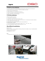
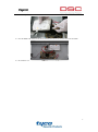
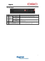
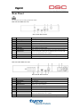
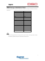
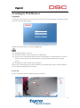
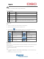
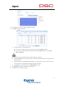
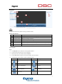
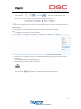
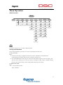
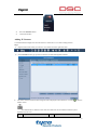
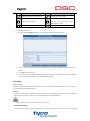
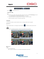
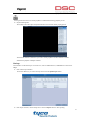
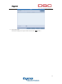
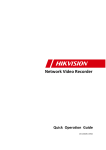
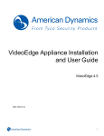
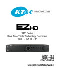
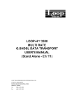
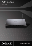
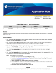
DSC-N114_Network_Video_Recorder Quick Start Guide 8200-1116-05 Regulatory information FCC information FCC compliance: This equipment has been tested and found to comply with the limits for a digital device, pursuant to part 15 of the FCC Rules. These limits are designed to provide reasonable protection against harmful interference when the equipment is operated in a commercial environment. This equipment generates, uses, and can radiate radio frequency energy and, if not installed and used in accordance with the instruction manual, may cause harmful interference to radio communications. Operation of this equipment in a residential area is likely to cause harmful interference in which case the user will be required to correct the interference at his own expense. FCC conditions This device complies with part 15 of the FCC Rules. Operation is subject to the following two conditions: 1. This device may not cause harmful interference. 2. This device must accept any interference received, including interference that may cause undesired operation. EU Conformity Statement This product and - if applicable - the supplied accessories too are marked with "CE" and comply therefore with the applicable harmonized European standards listed under the Low Voltage Directive 2006/95/EC, the EMC Directive 2004/108/EC, the RoHS Directive 2011/65/EU. 2012/19/EU (WEEE directive): Products marked with this symbol cannot be disposed of as unsorted municipal waste in the European Union. For proper recycling, return this product to your local supplier upon the purchase of equivalent new equipment, or dispose of it at designated collection points. For more information see: www.recyclethis.info. 2006/66/EC (battery directive): This product contains a battery that cannot be disposed of as unsorted municipal waste in the European Union. See the product documentation for specific battery information. The battery is marked with this symbol, which may include lettering to indicate cadmium (Cd), lead (Pb), or mercury (Hg). For proper recycling, return the battery to your supplier or to a designated collection point. For more information see: www.recyclethis.info. 1 Trademarks and Registered Trademarks • Windows and Windows mark are trademarks or registered trademarks of Microsoft Corporation in the United States and/or other countries. • HDMI, HDMI mark and High-Definition Multimedia Interface are trademarks or registered trademarks of HDMI Licensing LLC. • The products contained in this manual are authorized by HDMI Licensing LLC with the use right of the HDMI technology. • VGA is the trademark of IBM. • UPnPTM is a certification mark of the UPnPTM Implementers Corporation. Other names of companies and product contained in this manual may be trademarks or registered trademarks of their respective owners. 2 TABLE OF CONTENTS NVR Pre-Installation ....................................................................................................................................... 4 NVR Installation .............................................................................................................................................. 4 Hard Disk Installation ..................................................................................................................................... 4 Front Panel ....................................................................................................................................................... 6 Rear Panel ........................................................................................................................................................ 7 HDD Storage Calculation Chart ..................................................................................................................... 9 Accessing by Web Browser ............................................................................................................................ 10 Logging In................................................................................................................................................ 10 Live View ................................................................................................................................................. 10 Recording ................................................................................................................................................. 11 Playback ................................................................................................................................................... 13 Log query ................................................................................................................................................. 14 Menu Operation ............................................................................................................................................. 15 Menu Structure......................................................................................................................................... 15 Startup and Shutdown .............................................................................................................................. 15 Adding IP Cameras .................................................................................................................................. 16 Recording ................................................................................................................................................. 17 Instant Recording ............................................................................................................................. 17 All-day Recording ............................................................................................................................ 18 Playback ................................................................................................................................................... 18 3 NVR Pre-Installation The NVR is highly advanced surveillance equipment that should be installed with care. Please take into consideration the following precautionary steps before installation of the NVR. 1. Keep all liquids away from the NVR. 2. Install the NVR in a well-ventilated and dust-free area. 3. Ensure environmental conditions meet factory specifications. 4. Install a manufacturer recommended HDD. NVR Installation During the installation of the NVR: 1. 2. 3. 4. 5. 6. 7. 8. Use brackets for rack mounting. Ensure there is ample room for audio and video cables. When routing cables, ensure that the bend radius of the cables are no less than five times than its diameter. Connect both the alarm and RS-485 cable. Allow at least 2cm (≈0.75-inch) of space between racks mounted devices. Ensure the NVR is grounded. Environmental temperature should be within the range of -10 ºC ~ 55 ºC, 14ºF ~ 131ºF. Environmental humidity should be within the range of 10% ~ 90%. Hard Disk Installation Before you start: Disconnect the power from the NVR before installing a hard disk drive (HDD). A factory recommended HDD should be used for this installation. Tools Required: Screwdriver. Steps: 1. Remove the cover from the NVR by unfastening the screws on the rear and side panel. 2. Connect one end of the data cable to the motherboard of NVR and the other end to the HDD. 4 3. Connect the power cable to the HDD. 4. Place the HDD on the bottom of the device and then fasten the screws on the bottom to fix the HDD. 5. Re-install the cover of the NVR and fasten screws. 5 Front Panel No. Name Description Power 1 Status Indicator Status Tx/Rx Power indicator turns yellow when system is running. Status indicator blinks red when data is being read from or written to HDD. Tx/Rx indictor blinks yellow when network connection is functioning properly. Universal Serial Bus (USB) ports for additional devices such as 2 USB Interface USB mouse and USB Hard Disk Drive (HDD). 6 Rear Panel The rear panel vaires according to different models. DSC-N114-8/ DSC-N114-16 DSC-N114-8/ DSC-N114-16 No. Item Description 1 Power Supply DC 12V power supply. 2 Audio In RCA connector for audio input. 3 HDMI Interface HDMI video output connector. 4 LAN Network Interface 1 10 /100 /1000 Mbps self-adaptive Ethernet interface 5 Audio Out RCA connector for audio output. 6 VGA Interface DB9 connector for VGA output. Display local video output and menu. 7 USB Interface Universal Serial Bus (USB) ports for additional devices such as USB mouse and USB Hard Disk Drive (HDD). 8 Ground Ground (needs to be connected when NVR starts up). 9 Power Switch Switch for turning on/off the device. DSC-N114-8P/ DSC-N114-8P DSC-N114-8P/ DSC-N114-16P No. Item Description 1 Power Supply AC 100~240V 2 Audio In RCA connector for audio input. 3 HDMI Interface HDMI video output connector. 4 LAN Network Interface 1 10 /100 /1000 Mbps self-adaptive Ethernet interface 5 Audio Out RCA connector for audio output. 6 VGA Interface DB9 connector for VGA output. Display local video output and menu. 7 USB Interface Universal Serial Bus (USB) ports for additional devices such as USB mouse and USB Hard Disk Drive (HDD). 8 Ground Ground (needs to be connected when NVR starts up). 7 No. Item Description 9 Power Switch Switch for turning on/off the device. 10 Network Interfaces with PoE function Network interfaces for the cameras and to provide power over Ethernet. 8 HDD Storage Calculation Chart The following chart shows an estimation of storage space used based on recording at one channel for an hour at a fixed bit rate. Bit Rate 96K 128K 160K 192K 224K 256K 320K 384K 448K 512K 640K 768K 896K 1024K 1280K 1536K 1792K 2048K Storage Used 42M 56M 70M 84M 98M 112M 140M 168M 196M 225M 281M 337M 393M 450M 562M 675M 787M 900M 4096K 1.8G 8192K 3.6G 16384K 7.2G Please note that supplied values for storage space used is just for reference. The storage values in the chart are estimated by formulas and may have some deviation from actual value. 9 Accessing by Web Browser Logging In You can get access to the device via web browser. Open web browser, input the IP address of the device and then press Enter. The login interface appears. Input the user name and password, and click the Login button. The default IP address is 192.0.0.64. The default user name is admin, and password is VIDEO!edge23. You may use one of the following listed web browsers: Internet Explorer 6.0, Internet Explorer 7.0, Internet Explorer 8.0, Internet Explorer 9.0, Internet Explorer 10.0, Apple Safari, Mozilla Firefox, and Google Chrome. The supported resolutions include 1024*768 and above. When you log in for the first time, the system will remind you to install the Plug-in control. After the installation, you can configure and manage the device remotely. Live View The live view interface appears by default when you log in the device. 10 The live view interface may differ according to different models. Interface Introduction No. Name Description 1 Channel List 2 Live View Window Displays the image of channel, and multi-window division is supported. 3 Play Control Bar Play control operations are supported. 4 PTZ Control Displays the list of channels and the playing and recording status of each channel. Pan, tilt, zoom operations are supported, as well as preset editing and calling. Video Parameters 5 Brightness, contrast, saturation and hue of the image can be edited. Configuration Start Live View Steps: 1. In the live view window, select a playing window by clicking the mouse. 2. Double click a camera from the device list to start the live view. 3. You can click the button on the toolbar to start the live view of all cameras on the device list. Refer to the following table for the description of buttons on the live view window: Icon Description Icon Description Select the window-division mode Close audio Start all live view Stop two-way Audio Capture pictures in the live view mode Start all recording Previous/Next page Full screen Recording Before you start Make sure the device is connected with HDD or network disk, and the HDD or network disk has been initialized for the first time to use. Two recording types can be configured: Manual and Scheduled. The following section introduces the configuration of scheduled recording. Steps: 1. Click Remote Configuration> Camera Settings> Schedule Settings to enter Record Schedule settings interface. 2. Select the camera to configure the record schedule. 11 3. Check the checkbox of Enable Schedule to enable recording schedule. 4. Choose the day in a week to configure scheduled recording. 5. Click Edit to edit record schedule. 1) Configure All Day or Customize Record: If you want to configure the all-day recording, please check the All Day checkbox. If you want to record in different time sections, check the Customize checkbox. Set the Start Time and End Time. Up to 8 segments can be configured and each segment cannot be overlapped. 2) Select a Record Type. The record type can be Continuous, Motion, Alarm, Motion & Alarm, Motion | Alarm and VCA. 3) Check the checkbox of Select All and click Copy to copy settings of this day to the whole week. You can also check any of the checkboxes before the date and click Copy. 4) Click OK to save the settings and exit the Edit Schedule interface. 6. Click Advanced to configure advanced record parameters. 7. Click Save to activate the above settings. 12 Playback The playback interface may differ according to different models. Interface Introduction No. Name Description 1 Channel List Displays the list of channels and the playing status of each channel. 2 Playback Window Displays the image of channel. 3 Play Control Bar Play control operations are supported. 4 Time Line Displays the time bar and the records marked with different colors. 5 Playback Status Displays the playback status, including channel number and playback speed. 6 Calendar You can select the date to play. Start Playback Steps: 1. Click Playback on the menu bar to enter playback interface. 2. Click the camera from the device list for playback. 3. Select the date from the calendar and click Search. 4. Click the Play button to play the video file searched on the current date. 5. Use the buttons on the toolbar to operate in playback mode. Button Description Button Description Play Stop Slow down Full screen Play by single frame Capture Stop all playback Download Video clip 13 6. You can drag the progress bar with the mouse to locate the exact playback point. You can also input the time in the textbox and click button to locate the playback point. The color of the video on the progress bar stands for the different video types. Log query You can view and export the log files at any time, including operation, alarm, exception and information of device. Before you start: The Log function can be realized only when the device is connected with HDD or network disk. Steps: 1. Click Log on the menu bar to enter the Log interface. 2. Set the log search conditions to refine your search, including the Major Type, Minor Type, Start Time and End Time. 3. Click the Search button to start searching log files. 4. The matched log files will be displayed on the list. Up to 2000 log files can be found each time, and 100 log files can be displayed on each page. You can click the button to save the searched log files to local directory. 14 Menu Operation Menu Structure Menu Playback Export Manual HDD Record Camera Configuration Maintenance Shutdown Normal Record General Schedule Camera General System Info Logout Event Alarm Advanced Parameters OSD Network Log Information Shutdown Advanced Image Alarm Import/Export Reboot Holiday PTZ RS-232 Upgrade Motion Live View Default Privacy Mask Exceptions Net Detect Video Tampering User HDD Detect Video Loss VCA The menu structure may vary according to different models. Startup and Shutdown Proper startup and shutdown procedures are crucial to expanding the life of the NVR. To start your NVR: Steps: 1. Check the power supply is plugged into an electrical outlet. It is HIGHLY recommended that an Uninterruptible Power Supply (UPS) be used in conjunction with the device. 2. Press the POWER button on the front panel. The Power LED should turn green. The unit will begin to start. After the device starting up, the wizard will guide you through the initial settings, including modifying password, date and time settings, network settings, HDD initializing, and recording. To shut down the NVR: Steps: 1. Enter the Shutdown menu. Menu > Shutdown 15 2. Select the Shutdown button. 3. Click the Yes button. Adding IP Cameras You should add and configure the online IP cameras to enable the live view and recording function. Steps: 1. Right-click the mouse when you in the live view mode to show the right-click menu. 2. Select IP Camera in the pop-up menu to enter the IP Camera Management interface. 3. The online cameras with same network segment will be displayed in the camera list. Click the add the camera. button to The added camera is marked in white while the camera has not been added is marked in yellow. Explanation of the icons Icon Explanation Icon Explanation 16 Icon Explanation Icon Edit basic parameters of the camera Explanation Add the detected IP camera. The camera is disconnected; you can The camera is connected. click the icon to get the exception information of camera. Delete the IP camera 4. Advanced settings of the camera. To add other IP cameras: 1) Click the Custom Adding button to pop up the Add IP Camera (Custom) interface. 2) You can edit the IP address, protocol, management port, and other information of the IP camera to be added. 3) Click Add to add the camera. 4) (For the encoders with multiple channels only) check the checkbox of Channel No. in the pop-up window, as shown in the following figure, and click OK to finish adding. Recording Before you start: Make sure that the HDD has already been installed. If not, please install a HDD and initialize it. You can refer to the user manual for detailed information. Purpose: Two kinds of record types are introduced in the following section, including Instant Record and All-day Record. And for other record types, you may refer to the user manual for detailed information. After rebooting all the manual records enabled are canceled. Instant Recording On the live view window of each channel, there is a quick setting toolbar which shows on the bottom of the 17 window when you click on it. Click the icon to enable the record All-day Recording Steps: 1. On the live view window, right lick the window and move the cursor to the Start Recording option, and select Continuous Record or Motion Detection Record on your demand. 2. And click the Yes button in the popup Attention message box to confirm the settings. Then all the channels will start to record in the selected mode. Playback Play back the record files of a specific channel in the live view menu. Channel switch is supported. Option 1: Choose a channel under live view using the mouse and click the button in the shortcut operation menu. Only record files recorded during the past five minutes on this channel will be played back. Option 2: Steps: 1. Enter the Playback menu. Mouse: right click a channel in live view mode and select Playback from the menu. 18 Under multi-screen live view, record files of the selected channel will be played back. Pressing numerical buttons will switch playback to related channels during playback process. 2. Playback management. The toolbar in the bottom part of Playback interface can be used to control playing process. Just check the channel or channels if you want to switch playback to another channel or execute simultaneous playback of multiple channels. Backup Recorded files can be backed up to various devices, such as USB flash drives, USB HDDs or a DVD writer. Steps: 1. Enter Video Export interface. Choose the channel(s) you want to back up and click on the Quick Export button. 2. Enter Export interface, choose backup device and click Export button to start exporting. 19 3. Check backup result. Choose the recording file in Export interface and click button to check it. 20