1
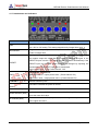
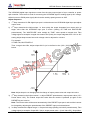
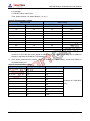
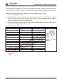
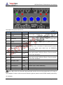
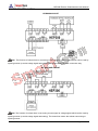
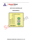
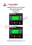
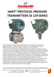
HEP300 ELECTRONIC POTENTIOMETER USER MANUAL SMARTGEN (ZHENGZHOU) TECHNOLOGY CO., LTD. Chinese trademark English trademark SmartGen — make your generator smart SmartGen Technology Co., Ltd. No.28 Jinsuo Road Zhengzhou Henan Province P. R. China Tel: 0086-371-67988888/67981888 0086-371-67991553/67992951 0086-371-67981000(overseas) Fax: 0086-371-67992952 Web: http://www.smartgen.com.cn http://www.smartgen.cn Email: [email protected] All rights reserved. No part of this publication may be reproduced in any material form (including photocopying or storing in any medium by electronic means or other) without the written permission of the copyright holder. Applications for the copyright holder’s written permission to reproduce any part of this publication should be addressed to Smartgen Technology at the address above. Any reference to trademarked product names used within this publication is owned by their respective companies. Smartgen Technology reserves the right to change the contents of this document without prior notice. Software Version Version Date Note 2014-10-20 1.0 Original release. 2015-10-08 1.1 Modify detail descriptions and typical application dirgram. HEP300 Electron Potentiometer User Manual CONTENT 1. OVERVIEW ................................................................................................................... 4 2. PERFORMANCE AND CHARACTERISTICS ............................................................... 4 3. SPECIFICATION ........................................................................................................... 4 4. OPERATION ................................................................................................................. 5 4.1 Potentiometer and Indicators ...................................................................................... 5 4.2 Up/Down Digital Input Port Adjusting ......................................................................... 6 4.3 Vin Analog Input Port Adjusting .................................................................................. 8 5. CONNECTIONS ............................................................................................................ 9 6. TYPICAL APPLICATION ............................................................................................. 10 7. INSTALLATION ........................................................................................................... 11 7.1 Overall Dimension and Panel Cutout ....................................................................... 11 7.2 Battery Voltage Input ................................................................................................ 11 HEP300 Electron Potentiometer 2015-10-08 Version 1.1 Page 3 of 11 HEP300 Electron Potentiometer User Manual 1. OVERVIEW Using the powerful Microprocessor, HEP300 Electronic Potentiometer module integrates digitization, intelligentization and network technology to achieve converting the digital signal or analog signal to target voltage, current or PWM signal. It is not only used for converting the digital output signal (raise/drop speed, boost/reduce voltage) of sync controller or power split controller to analog signal (±10V voltage, ±20mA current or PWM pulse signal) which can be used by speed governor or AVR, but also can convert the DC voltage signal to DC current signal or PWM signal when transmission distance is large and voltage signal seriously attenuating (with droop PWM signal). The module can set the parameters range simply by regulates the potentiometer on the panel. It is reliable and easy to use and it can be widely used in electronic speed/voltage regulating and parallel system. 2. PERFORMANCE AND CHARACTERISTICS All the parameters can be set simply via potentiometers on the panel: TIME/s (Slope), PRESET/%, LIMIT/%, PWM DUTY/%; Two kinds of input modes: Digital signal (UP, DOWN) and analog voltage signal; Various output signal: DC±10V, DC±20Ma, 500Hz(0-100)% pulse width PWM; Link port enables the data can be input/output via PC software. Widely power supply range DC(8~35)V, suitable to different starting battery voltage environment; 35mm rail mounting; Modular design, pluggable terminal, compact structure with easy installation. 3. SPECIFICATION Items Contents Working Voltage DC24V, also can be used for DC12V system. Overall Consumption <3W(Standby mode: ≤2W) Integral Time 2.5s-125s Input Voltage DC±10V Output Voltage DC±10V Output Current DC±20mA PWM Output 6V 500Hz(0-100)% Pulse Width PWM Droop PWM Output 6V 500Hz(0-100)% Pulse Width PWM Time from input to output <100ms Overall Dimensions 89.7mm x 71.6mm x 60.7mm Working Condition Temperature: (-25~70)ºC; Humidity: (20~93)%RH Storage Condition Temperature: (-25~70)ºC Weight 0.24kg HEP300 Electron Potentiometer 2015-10-08 Version 1.1 Page 4 of 11 HEP300 Electron Potentiometer User Manual 4. OPERATION 4.1 Potentiometer and Indicators Items Description Integral time potentiometer; Adjust slope: i.e. how quickly the output integrates TIME from -10V to 10V setting. This setting determines by Integral time only. Integral time multiplier potentiometer; This value multiply by ―TIME‖ value MULTIPLIER equals to Integral time. Output preset/% potentiometer; output preset value is adjust central voltage. The module output this value after the module is powered up again or the PRESET IN port is active. The Preset value will be saved automatically if the PRESET PRESET input port is active while it cannot be changed by adjusting the potentiometer if the PRESET input port is deactivated. Output preset value = -5V+ Preset Value% *10V Output limit/% potentiometer LIMIT Output Min. value = output preset value - (Preset Value%*5V) Output Max. value = output preset value + (Preset Value%*5V) PWM DUTY Power DROOP PWM duty ratio Indicator (Green) Vin EN Indicator (Red) DOWN Indicator (Red) UP Indicator (Red) Illumination indicates the power is normal. Illumination indicates Vin EN input port close. Illumination indicates DOWN input port close; It is flashing if the output value is set as the lower limit value. Illumination indicates UP input port close; It is flashing if the output value is set as the upper limit value. HEP300 Electron Potentiometer 2015-10-08 Version 1.1 Page 5 of 11 HEP300 Electron Potentiometer User Manual 4.2 Up/Down Digital Input Port Adjusting The UP/DOWN digital input signals are come from the relay output signal of sync controller or power split controller. The module is used for converting the UP/DOWN signal to analog signal (±10V voltage, ±20mA current or PWM pulse signal) which can be used by speed governor or AVR. Adjust Sequence: 1) 1st Step: determine Vin EN digital input port is void and enter into UP/DOWN digital input port adjust output mode. 2) 2nd Step: determine the Adjust slope: i.e. how quickly the output integrates from output value to target value after the UP/DOWN input port is active. (Setting via TIME and MULTIPLIER potentiometer). The ―MULTIPLIER‖ value multiply by ―TIME‖ value equals to Integral time. Take voltage signal as example: Integral time means how quickly the output integrates from -10V to 10V setting; Adjust slope means how much voltage value is adjusted in unit time. For example: If: TIME=10s; MULTIPLIER=5 Then: Integral time=50s; Adjust slope=0.4V/s (to be defined to be (10V-(-10V))/50s); as shown below: Note: Adjust slope is not changing with the change of output preset value and output limit value. 3) 3nd Step: determine the Adjust central: i.e. adjust PRESET potentiometer, output preset value (-5V+ Preset Value *10V). The module output this value after the module is powered up again or the PRESET IN port is active. Note: The Preset value will be saved automatically if the PRESET input port is active while it cannot be changed by adjusting the potentiometer if the PRESET input port is deactivated. 4) 3rd Step: determine the Adjust range: i.e. Output limit range (Setting via Limit/% potentiometer); Take voltage signal as example: Output Min. Value= output preset value – (Limit Value*5V), Output Max. HEP300 Electron Potentiometer 2015-10-08 Version 1.1 Page 6 of 11 HEP300 Electron Potentiometer User Manual Value= output preset value + (Limit Value*5V). For example: If: PRESET=90%; LIMIT=40% Then: Adjust Central =4V; Adjust Range=(2~6)V. Specific Correspondence Table Adjust Central Adjust Range PRESET (%) Voltage (V) LIMIT (%) Voltage (V) 0 -5.0 0 ±0 10 -4.0 10 ±0.5 20 -3.0 20 ±1.0 30 -2.0 30 ±1.5 40 -1.0 40 ±2.0 50 0.0 50 ±2.5 60 1.0 60 ±3.0 70 2.0 70 ±3.5 80 3.0 80 ±4.0 90 4.0 90 ±4.5 100 5.0 100 ±5.0 Droop PWM value must be determined if the Droop control function is implemented in speed 5) governor or AVR and the control signal is 500Hz PWM. The Droop PWM Duty can be obtained simply by adjusting the PWM DUTY potentiometer. 6) After above parameters are setting, users can control the output voltage, current and PWM via UP/DOWN input port. Specific Correspondence Table Output Voltage (V) Output Current (mA) Output PWM (%) -10 -20 0 -8 -16 10 -6 -12 20 -4 -8 30 -2 -4 40 0 0 50 2 4 60 4 8 70 6 12 80 8 16 90 10 20 100 HEP300 Electron Potentiometer 2015-10-08 Output DROOP (%) Depends on PWM Duty only Version 1.1 Page 7 of 11 HEP300 Electron Potentiometer User Manual 4.3 Vin Analog Input Port Adjusting The VIN analog input signals are come from the voltage output signal of speed governor controller or AVR controller. The module is used for converting the VIN signal to analog signal (DC ±10V voltage, DC ±20mA current or PWM pulse signal) which can be used by speed governor or AVR. 1) Active Vin EN digital input port. 2) Droop PWM value must be determined if the Droop control function is implemented in speed governor or AVR and the control signal is 500Hz PWM. The Droop PWM Duty can be obtained simply by adjusting the PWM DUTY potentiometer. 3) After above parameters are setting, users can control the output voltage, current and PWM via VIN input port. The voltage effective range is ±10V. Specific Correspondence Table Input/Output Voltage (V) Output Current (mA) Output PWM (%) -10 -20 0 -8 -16 10 -6 -12 20 -5 -10 25 -4 -8 30 -2 -4 40 0 0 50 2 4 60 4 8 70 5 10 75 6 12 80 8 16 90 10 20 100 HEP300 Electron Potentiometer 2015-10-08 Output DROOP (%) Depends on PWM Duty only Version 1.1 Page 8 of 11 HEP300 Electron Potentiometer User Manual 5. CONNECTIONS Description of terminal connections: No. Function Cable Size Description 2 1 DC B- 1.5mm 2 DC B+ 1.5mm2 Power supply(8-35V) 3 Vin EN - 1.0mm2 4 Vin EN IN 1.0mm2 VIN DC voltage input; When the input is ―close to activate‖, then 14 terminal, 15 terminal and 18 terminal output will be controlled by analog voltage VIN. 5 Vin IN- 1.0mm2 2 6 Vin IN+ 1.0mm 7 PRESET - 1.0mm2 8 PRESET IN 1.0mm2 9 DOWN - 1.0mm2 10 DOWN IN 1.0mm2 11 UP - 1.0mm2 12 UP IN 1.0mm2 13 OUTPUT COM 1.0mm2 14 OUTPUT VDC 1.0mm2 15 16 OUTPUT mA PWM DROOP Connect to voltage output signal of speed governor or AVR. PRESET/% Potentiometer output; When the input is ―close to activate‖, then 14 terminal, 15 terminal and 18 terminal output the preset value which set via PRESET/% Potentiometer. Connect to the relay output signal of sync controller or power split controller. When the input is ―close to activate‖, the set value decreases. Connect to the relay output signal of sync controller or power split controller. When the input is ―close to activate‖, the set value increases. Output±10V 1.0mm 2 Output±20mA 1.0mm 2 DROOP output; 500Hz PWM Duty 2 17 PWM GND 1.0mm 18 PWM OUT 1.0mm2 500Hz PWM Duty Note: LINK interface is parameters programmable interface that can be programmed by PC using an SG72 adapter. If there is need to remote control the genset, please use the SG485 module produced by our company. HEP300 Electron Potentiometer 2015-10-08 Version 1.1 Page 9 of 11 HEP300 Electron Potentiometer User Manual 6. TYPICAL APPLICATION UP/DOWN ADJUST Note: The function of resistor here is converting current signal to voltage signal which can be used by speed governor (to avoid voltage signal attenuating). Dotted line means another connection way. DC VOLTAGE ADJUST Note: The function of resistor here is converting current signal to voltage signal which can be used by speed governor (to avoid voltage signal attenuating). The dotted line means the resistor connecting to speed governor. HEP300 Electron Potentiometer 2015-10-08 Version 1.1 Page 10 of 11 HEP300 Electron Potentiometer User Manual 7. INSTALLATION 7.1 Overall Dimension and Panel Cutout 7.2 Battery Voltage Input HEP300 module can suit for widely range of battery voltage DC(8~35)V. Negative of battery must be connected with the engine shell. The diameter of wire which from power supply to battery must be over 1.5mm2. If floating charge configured, please firstly connect output wires of charger to battery’s positive and negative directly, then, connect wires from battery’s positive and negative to controller’s positive and negative input ports in order to prevent charge disturbing the controller’s normal working. HEP300 Electron Potentiometer 2015-10-08 Version 1.1 Page 11 of 11