1
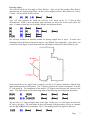
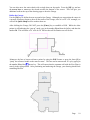
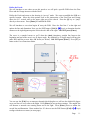
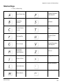
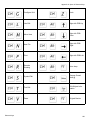
Apex v4.1.x Medina Assessor – Introductory Tutorial
Apex v4.1.x Medina Assessor
Apex v4.1.x Medina Assessor includes several User Interface updates from the v4.0 and earlier
releases. The Medina™ products represent our 4th generation of property sketch and area
calculation software application for desktop & notebook computers. Apex Assessor sketch is
designed to be able to run as a standalone application or as an integrated sketch tool within a
CAMA or other property record system. Apex Assessor has full printing and publishing capabilities
and the sketch files can also be automatically saved to multiple image file formats as well as .SHP
files for GIS & Mapping department needs.
Video Tutorials:
We are developing a whole new set of video tutorials and instructional aids that will provide a
valuable additional training tool for you. The videos will be able to be access from our Mass
Appraiser / Assessor product page at www.apexwin.com/v5/assessor_v4.php. As of October, the
following videos are available and we will try to add about one additional video each week. These
video tutorials will enhance your drawing skills and can be viewed at your convenience.
What’s ew – Overview of UI changes and drawing features
Basic Drawing Concepts
ew User Interface – ew layout and new features
Ribbon Bar – More detail on this unique UI design
Clone – Specific instruction for using Clone Area function
WebEx Training:
Apex offers FREE WebEx training classes weekly. Check for upcoming classes on the Medina
(desktop) or the Nexus (tablet) drawing tools at: www.apexwin.com/v5/training/new_training.php
This Tutorial:
The 1st Drawing Lesson will guide you through sketching a simple rectangle Living Area and then
adding a Garage. The Lesson teaches the drawing methods of using the mouse, using the arrow
keys and then using the direct keyboard input drawing methods. The 2nd Drawing Lesson is the a
more complex building structure and focuses on using the keyboard drawing method. This tutorial
was originally designed to be used for our On-Site Training services in conjunction with an Apex
instructor.
For a complete User Manual with multiple, in-depth drawing lessons, please refer to the On-Line
Manual (PDF file) located under the Help Menu within the software application (November, 2007).
Page
1
Drawing Lesson #1
The Define Area dialog:
When beginning a new sketch, Apex v4 will initially open a series of Define Area dialogs so you
can select the appropriate Area and Sub Area options. You are simply naming the type of area you
would like to draw (Living Area, Garage, Porch, etc…). Apex does make a provision for a “Draw
First / Define Later” method but that is covered in more advanced tutorials.
Area categories with a “+” in front of them have Sub-Areas within that group. The Area Code
Table can be modified to use the local jurisdictions local Area Naming / Coding conventions.
Please see the On-Line Manual for information on making modifications to this table.
You can maneuver through these dialogs by clicking on the desired area definition with mouse,
using the arrow keys and [Enter] key, or simply typing in the first few letters of the area
description. Use the mouse to select the GLA category by left clicking on this line. Note that there
are pre-defined Sub-Areas in the default area code table. To select the GLA1 / First Floor, left click
on the [OK] button or press the [Enter] key to return to the drawing pad.
The cursor will appear as a white arrow pointer and nothing will happen until you either press the
[Enter] key or left click with the mouse to go to the “pen down” drawing mode. This will establish
the Point of Beginning (POB) of the sketch you are about to draw.
A. Draw with the Mouse:
Left click with the mouse and note that the white arrow will become a cross hair. You have
established the POB and you can begin drawing by simply dragging the mouse to create a
line the desired length. Notice that horizontal or vertical lines will initially display in a red
color. Any angled line will be displayed in a fuchsia color and the Rise & Run dimensions
will be displayed as construction lines.
Drag a line 40’ to the right. Once you have the desired line length, left click with the mouse
to anchor the line. The focus will shift to the dimension label so you can place it where you
want or use the roller wheel on the mouse to change the font sizes up or down. Left click
again to anchor the dimension and the focus will return to the end of the first line. You are
ready to draw the 2nd line.
ote: The line dimensions will increase in whole foot increments by default. To draw in
feet and decimal feet, hold down the [Shift] key. It is noticeably more difficult to draw with
the mouse when drawing in feet and decimal feet but it is possible.
Page
2
Draw a line 20’ down. Left click to anchor the line & left click again to anchor the
dimension.
OrthoMetric drawing tool for enhanced mouse drawing: On the left side of the screen
are several additional tools (can also be activated from the Configuration set up). For this
tutorial, activate the OrthoMetric drawing tool which will hold the mouse drawn lines to 45
degree increments. This tool helps ensure your corners are drawn square. If you hold down
the shift key while drawing with the OrthoMetric drawing tool activated, you will be able to
draw a line at any angle.
Draw the horizontal line to 40’ to the left, left click to anchor the line and left click again to
anchor the dimension.
Draw the remaining 20’ line back to the POB. You will see a small “POB” display on
screen when you drag the curser near the left end of the first 40’ line. If you have your
sound turned on, you will also hear a click or pop to indicate you have returned to the POB.
Left click to anchor the line and then again to anchor the dimension.
Apex will display the Area Name (First Floor) as text in the box. Use the mouse to position
the label. The roller wheel can be used to increase or decrease the font size. Left click to
anchor the Area Name. The Area Calculation will post to the drawing next. Left click to
anchor this text item after positioning it.
B. Draw with the Keyboard:
Define another Area by 1) Left click on the Define Area button in Command Pad to the
right. 2) Go to the Draw Menu and click the Define Area button. 3) Press the [F4] key for
the keyboard shortcut.
When the Define Area dialog opens, you can maneuver down and up the list of categories
with the [] or [] keys. For this tutorial, maneuver down to the Garage category and
press the [Enter] key. Since there is only one Garage option in the default Area Code
Table, a 2nd dialog box will open showing the default details of this area. While this dialog
box is open, you can press the [Enter] Key to finalize the selection of the Garage and return
to the drawing pad (no requirement for using the mouse).
Page
3
Maneuvering the curser to a specific POB: The white pointer will appear somewhere on
the drawing pad. To create a POB of the Garage at a specific location, press the [J] key to
“jump to the nearest corner”. You can maneuver the curser position to a predetermined
position by tapping the [] [] [] or [] arrow keys to move the curser in 1’ increments
or typing in the specific distance from the current location.
ote: You can use the mouse to position the white pointer near a specific corner, press the
[J] key to jump to that corner and then use the arrow keys or type in a specific distance and
direction to move the curser to the actual POB for the new area.
For this tutorial, position the white pointer near the upper right corner of the existing sketch.
Press the [J] key to jump to this corner. Now press the [] arrow key 3 times to move the
pointer down 3’ (you can also press the [3] key & then the [] arrow key to move the
pointer down 3’).
Now press the [Enter] key to establish the POB of the Garage 3’ down from the upper right
corner. Draw a 20’ line to the left by 1) Pressing the [] arrow key 20 times, 2) Press &
holding the [] arrow key until the line is 20’ long or 3) Simply pressing the [2] key, then
the [0] key and then the [] arrow key.
The 20’ line will be drawn to the right. Press the [Enter] key to anchor the line. You can
use the arrow keys to change the position of the dimension (holding down the [Shift] key &
arrow keys will move the dimension in 1/10’ increments). You can increase or decrease the
font size by pressing the [+] or the [-] keys. Press the [Enter] key to anchor the dimension.
Next, draw a 17’ line down by pressing the [1] key, the [7] key and the [] arrow key.
Press the [Enter] key to anchor the line and then press the [Enter] key again to anchor the
dimension.
Draw the 20’ line back to the left by pressing the [2] key, the [0] key and the [] arrow key.
Press the [Enter] key twice to anchor the line and the dimension.
The last 17’ line has to be drawn back to the POB in order for Apex to close the Garage
polygon. Rather than typing in the [1], the [7] and the [] arrow keys, you can use the [A]
key as the short cut for AutoClose feature. Press the [Enter] key one time to anchor the
last line of the Garage. While the 17’ dimension is still red, press the [Space Bar] or the
[Delete] key to remove it since it is repetitious.
The Area Name (Garage) will be posted as text in the polygon you have just drawn. You
can maneuver the position of this label with the arrow keys or increase or decrease the font
size by pressing the [+] or the [-] keys. Press the [Enter] key to anchor the label. Next the
Area Calculation will post to the drawing. Press the [Enter] key to anchor this text.
Page
4
Drawing Lesson #2
The following sketch is more complex and includes drawing angles, quick shapes and a curve
example. Although you can draw the sketch from this lesson using the mouse, this tutorial is
primarily designed to introduce you to additional keyboard drawing techniques and short-cuts.
Open a new sketch file (File Menu, New). You will be drawing the following sketch:
Begin the Sketch:
For this tutorial, define the first area by selecting the GLA, Gross Living Area option and then
select the GLA1, First Floor option on the Sub-Area dialog. After Defining the Area, you will be
back to the drawing pad area. The curser is displayed as a white arrow pointer indicating the “Pen
Up” mode. It can be moved with the mouse or with the arrow keys or other movement tools to a
different point of beginning or to a strategic location on an existing sketch. Since this is the first
area to be drawn, simply press the [Enter
[Enter]
nter] key on your keyboard. The arrow will change to a circle
with a cross hair to indicate the “Pen Down” or drawing mode. You are establishing the Point of
Beginning (POB).
ote: You can also left click with the mouse to activate the “Pen Down” mode and draw with the
mouse. However, this tutorial will focus on keyboard entry and use of numerical information for
the measurements to complete this sketch.
Keyboard Drawing:
Apex allows you to re-center and re-scale the sketch at any time so it doesn’t really matter where
you establish the POB. Type the numbers [2] & [4] and then press on the [] arrow key to draw
the first line 24’ to the right. Press the [Enter] key to anchor the first line. Notice that the
dimension is still free floating and can be moved with the mouse, the arrow keys or other movement
tools to a more strategic location. For now, use the default dimension location and press the
[Enter] key again to anchor the 24’ dimension. You have completed the first line of the sketch.
Draw the line segments on the following page using the keystrokes indicated:
Page
5
Line Drawing using keyboard:
[9] [.] [8]
[ ]
[Enter]
[Enter]
[4]
[ ]
[Enter]
[Enter]
[7] [.] [2
[2]
[ ]
[Enter]
[Enter]
[10]
[ ]
[Enter]
[Enter]
[3]
[ ]
[Enter]
[Enter]
[10]
[ ]
[Enter]
[Enter]
Your sketch may look like the following:
Re-center the sketch by pressing the [C] key on the keyboard. You can re-center the sketch as often
as necessary. Continue drawing the next few lines and re-center [C] as often as necessary:
[3] [5]
[ ]
[Enter]
[Enter]
[2] [0]
[ ]
[Enter]
[Enter]
[8]
[ ]
[Enter]
[Enter]
[6]
[ ]
[Enter]
[Enter]
[6]
[ ]
[Enter]
[Enter]
[2]
[ ]
[Enter]
[Enter]
Your sketch should look something like this:
Page
6
Drawing Angles:
The next line will be the first angle of a Bay Window. Apex can use the standard “Rise & Run”
measurements for drawing angled lines. In this case the angled wall has a Rise & Run of 2’ left by
2’ down. The keystrokes for this wall are:
[2]
[ ]
[2]
[ ]
[Enter]
[Enter]
Apex will draw calculate the length the wall has to be based on the 2’x 2’ Rise & Run
measurements. BTW, it does not matter which direction you draw first as the result will be the
same. Continue to draw the rest of the Bay Window and subsequent lines:
[6]
[ ]
[Enter]
[Enter]
[2]
[ ]
[2]
[ ]
[2]
[ ]
[Enter]
[Enter]
[1] [5]
[ ]
[Enter]
[Enter]
[Enter]
[Enter]
We will now introduce an alternate method for drawing angled lines in Apex. In some cases
obtaining the Rise & Run measurements may be very difficult if not impossible. Apex allows you
to enter the actual degree of angle along with the wall length to calculate the Rise & Run for you.
In the sketch above, the angled wall is turning to the left at 53 degrees (Reference Mite-R-Gage
angle measuring tool and discussion). The 53 degrees represent the “degree of departure” from the
15’ wall going up. The compliment of this angle is 127 degrees and represents the “Interior of the
angle”. This angled wall can be drawn using either of the following sets of keyboard keystrokes:
[2] [0]
[L]
[5] [3
[3]
[Enter]
[Enter]
[Enter]
[Enter]
[Enter]
[Enter]
OR
[2] [0]
[L] [I]
[1] [2] [7]
The next line is 15’ long and angles back to the right. In this case, it is a 90 degree turn from the
20’ line we just drew. The turn feature in Apex will assume 90 degrees unless you key in a number
after the [L] or [R] direction commands. The 15’ line angling back at 90 degrees is drawn as:
[1
[1] [5
[5]
[R]
[Enter]
[Enter]
[Enter]
Page
7
Call to POP:
In the lower right corner of the screen you will notice a series of measurements indicating the
distance and direction back to the POB. This information is updated each time that the line and
dimension are anchored and can help you determine if the building is going to square or if
adjustments may be required. In the image below, we see that the call back to POB is 6.9’ to the
right and 14’ up.
If your field drawing or notes tell you that the vertical line should actually be 16’, you have to
determine what vertical line(s) on the opposite side need to be adjusted. For this tutorial, let’s
change the 35’ wall to 37’.
Delete and Insert Editing Tool:
Apex allows you to use the [Delete] key to erase one line at a time to go back to the 35’ wall. To
erase all the way to the 35’ line, you will press the [Delete] key 13 times. Redraw the vertical wall
37’ down and anchor the line and the dimension.
Rather than having to redraw each of the subsequent walls, Apex has memorized each wall distance
and direction. Press the [Insert] key one time for each line that you want to replace, including the
angled walls. After Inserting the last 15’ angled wall, your new call to POB will be 6.9’ to the right
and 16’ up. (Delete back - Insert forward)
Alignment Tool:
Although we could type in the 6.9’ and 16’ wall lengths, Apex provides Alignment and Auto Close
features. The Alignment tool ensures that the 6.9’ horizontal line matches exactly to the POB
position above. To use the Alignment tool, press and hold down the [Ctrl] key and then press the
[] arrow key. The line will “pop” to the right until it comes into alignment with another reference
point on the sketch. As shown below, it will align with the POB as well as with both ends of the
15’ vertical line. (See Reference Manual for configuration options for the Alignment tools). Press
the [Enter] key twice to anchor the 6.9’ line and the dimension.
Page
8
Auto Close Tool:
For the final line to be drawn, you can simply press the [A] key to draw the remaining 16’ wall and
the first area polygon will be completed. Apex will automatically post the Area Name as text and
you can position it with the mouse, the arrow keys or other movement tools. Press the [Enter] key
to anchor the Area Name and then the Area Calculation will also appear as text information on the
sketch. Position this item and then press [Enter] to anchor it also. Your drawing should look
something like this:
Drawing Subsequent Areas / Quick Shape Tool:
We’ll draw the Garage next and it will attach to the First Floor along the 24’ wall at the top. First,
let’s re-scale the sketch and reposition it down a few feet to make room for the Garage. The shortcut to re-scale the sketch is the [Ctrl] key and the [R] key.
The Scale dialog will open and you can select various scale options with the mouse but note that the
dialog will open with the focus on the Custom scale. You can simply type in the number you want
to re-scale to. In this case, type in the number 15 and press the [Enter] key. The sketch will be
rescaled to 1:15 and you may need to re-center the sketch.
Page
9
You can also move the entire sketch with a single short cut keystroke. Press the [M] key and use
the arrow keys to maneuver the sketch towards the bottom of the screen. This will give you
additional room at the top of the drawing page to draw the Garage.
Define the Garage:
Use the [F4] key to define the next area and select Garage. Although you can position the cursor in
a strategic location to begin to draw all four walls of the Garage, since it is a 24’x 20’ rectangle, we
will use the Quick Shape tool for another short cut.
After defining the Garage, DO NOT press the [Enter] key to establish a POB. While the white
pointer is still indicating the “pen up” mode, type in the number 24 and then the [x] key and then the
number 20. This will draw a 24’ wide by 20’ tall box that will be floating on your screen.
Maneuver the box to known reference points by using the POP feature or press the letter [J] to
“jump” the reference handle to the nearest corner. The box can be maneuvered 20’ up by typing in
the number 20 and the [] arrow key. This will ensure that the common wall with the First Floor is
exactly in the right position. After positioning and anchoring the Garage, your drawing should look
something like this:
Page
10
Define the Porch:
We will introduce a new short cut on this porch so we will pick a specific POB where the First
Floor and the Garage intersect with the Porch.
Define the Porch and return to the drawing in “pen up” mode. We want to establish the POB at a
specific location. Move the white pointer close to the intersection of the First Floor and Garage
above the 9.8’ vertical wall on the upper right part of the sketch. Press the [J] key to “jump”
directly to that corner. Press [Enter] to establish the POB.
We will introduce a curve that begins 6’ away the POB. Draw the first line 6’ to the right and
anchor the line and dimension. Next, use the POP feature ([Ctrl] & [] keys) to determine that the
distance to the right alignment point of this sketch is 10’ to the right – DO OT press [Enter].
The curve is a rounded corner so we’ll draw the chord (imaginary straight line between the
beginning and end of the curve) at a 45 degree angle. By definition, a 45 degree angel will have the
same Rise and Run so now draw 10’ down (see below). DO OT press [Enter]. Press [F7] to
bring up the Curve Functions dialog.
You can use the [Tab] key to maneuver through this dialog but we will use the default 90 degree
curve and leave it set to turn to the Right. Press [Enter] to accept these settings. The angled line
will become a smooth curve turning down and to the right. Press [Enter] twice to anchor the
curved line and dimension. Draw another line 10’ down or use the POP feature ([Ctrl] & [] keys)
to align with the next corner (see next page)
Page
11
Curve Example:
Auto Trace Feature:
Although we know that the common walls will finish the Porch, the software needs to be instructed
where those lines should exist. The Auto Trace feature is like Auto Close except it will follow a
series of common walls on its path back to the POB. By pressing [Cntrl] and the [F3] keys at the
same time, Apex will automatically trace the 6 remaining walls back to the POB we established at
the intersection of the 24’ horizontal wall and 9.8’ vertical wall. The Area Name and Calculation
text will automatically post to the sketch image. Your drawing should look like the following:
This concludes the tutorial on the Apex v4 Assessor Sketch software.
Apex Software – San Antonio, TX
Sales: 800-858-9958 Technical / User Support: 888-308-2722
Page
12
otes:
______________________________________
____________________________________
______________________________________
____________________________________
______________________________________
____________________________________
______________________________________
____________________________________
______________________________________
____________________________________
______________________________________
____________________________________
______________________________________
____________________________________
______________________________________
____________________________________
______________________________________
____________________________________
______________________________________
____________________________________
______________________________________
____________________________________
______________________________________
____________________________________
______________________________________
____________________________________
______________________________________
____________________________________
______________________________________
____________________________________
______________________________________
____________________________________
______________________________________
____________________________________
______________________________________
____________________________________
______________________________________
____________________________________
______________________________________
____________________________________
______________________________________
____________________________________
______________________________________
____________________________________
______________________________________
____________________________________
______________________________________
____________________________________
______________________________________
____________________________________
______________________________________
____________________________________
______________________________________
____________________________________
______________________________________
____________________________________
______________________________________
____________________________________
______________________________________
____________________________________
______________________________________
____________________________________
______________________________________
____________________________________
______________________________________
____________________________________
______________________________________
____________________________________
______________________________________
____________________________________
______________________________________
____________________________________
______________________________________
____________________________________
______________________________________
____________________________________
______________________________________
____________________________________
______________________________________
____________________________________
______________________________________
____________________________________
______________________________________
____________________________________
______________________________________
____________________________________
______________________________________
____________________________________
______________________________________
____________________________________
______________________________________
____________________________________
______________________________________
____________________________________
Page
13
A p p e n d i x
A
Apex v4
Shortcut Keys
The following provides a quick overview of
the shortcut keys found throughout the applciation. Remember that there are multiple
ways to access these tools. Some tools can be
accessed by using a shortcut key or they can
be also be invoked from the Menu Bar or
Command Pad.
103
Appendix A: Apex v4 Shortcut Keys
Shortcut Keys
* = Survey Mode Only
Auto-Close Area
Parallel Dimension/
Label/Symbol
Close Bay
Window
Symbols
Center Sketch
Curve*
Text
Fill Area/Flip
Unzoom (Zoom
Out)
Go to Corner
Vertical Dimension/
Label/Symbol
Horizontal
Dimension/
Label/Symbol
Zoom In
Enlarge Dimension
Jump to Point
Shrink Dimension
LIne Attributes
Open User’s Guide
Move Sketch
Shortcut Keys
104
Appendix A: Apex v4 Shortcut Keys
Shortcut Keys
Save File
Save As
Open File
Clone Area
Define Area
Swap POB
Free Form
Toggle
Close Apex
View
Calculations
Draw First
Curve
Properties
Scroll Port Up
Toggle
Alignment
Scroll Port Down
Test Close
Select All Items
Refresh Screen
Copy
View/Edit Deed
Calls
Dimension Edit
105
Appendix A: Apex v4 Shortcut Keys
Shortcut Keys
Configure Grid
Undo
Line Edit
Align with POB Up
Move Area
Align with POB
Down
New File
Align with POB
Right
Print
Align with POB Left
Rescale
Drawing
Auto-Jump
Symbol Edit
Reopen Closed
Area @
Text Edit
Edit Subject Information
Paste
Original Monitor
106
Appendix A: Apex v4 Shortcut Keys
Shortcut Keys
Auto-Trace
Pop Left to Align
Close
Draw Parallel
Angled Wall
Suspend Area
Repeat Last Symbol
Configure
Alignment
Repeat Last Text
Enhanced Test
Close
Redo
Toggle
Dimensions
Enhanced Pop Up
Pop Up to Align
Enhanced Pop
Down
Pop Down to
Align
Enhanced Pop
Right
Pop Right to
Align
Enhanced Pop Left
107


![manual [372769 bytes]](http://vs1.manualzilla.com/store/data/005891066_1-6553408cfa4c941a2bbbbb48a824c132-150x150.png)


![USER MANUAL v10 - CA Real Estate Products [WEB].indd](http://vs1.manualzilla.com/store/data/005903983_1-a62231e758f044444a417010828feda3-150x150.png)
