1
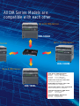
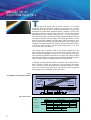
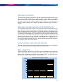
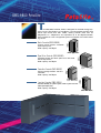
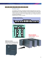
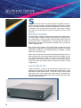
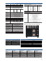
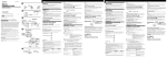
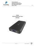
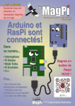
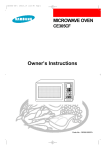
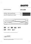
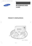
High Performance
Data Storage System
DIR-1000H
DMS-8800
S
ony DIR-1000 Series Digital Data Recorders conform to
the ANSI ID-1 standard (ANSI X3.175-1990), providing storage
capacity of up to 96 GBytes on a single standard cassette, at
user data rates from 1 MBytes/sec to 64 MBytes/sec. Offering
user data rates of up to 32 MBytes/sec, the first three models
in the series have been accepted around the world in a growing range of instrumentation recording and mass storage
applications. The latest model, the DIR-1000H, provides a maximum rate of 64 MBytes/sec (512 MBits/sec), the fastest data
rate within the DIR-1000 Series.
In response to unprecedented demand for data storage from
the ever growing community of users of high-performance
computer systems, Sony has continued to develop its range of
high-performance data storage solutions to meet a variety of
applications for both instrumentation and computer mass
storage. We offer a wide selection of system interface products, including a SCSI-2 Fast/Wide controller.
Our selection of mass storage solutions has recently been
extended by the addition of the DMS-8800 PetaSite Series,
which offers capacities from 6.8 terabytes to 3 petabytes — a
true flagship system for digital mass storage applications.
Up to 32 MBy
DIR-1000
All DIR Series Models are
compatible with each other
Up to 64 MBytes/sec
DIR-1000H
Up to 16 MBytes/sec
ytes/sec
DIR-1000M
Up to 8 MBytes/sec
Tape Drives: DIR-1000 Series
DIR-1000H
DIR-1000
DIR-1000M
DIR-1000L
32, 50 & 64 MBytes/sec
1.3, 2, 4, 8, 16 & 32 MBytes/sec
2, 4, 8 & 16 MBytes/sec
1, 1.3, 2, 4 & 8 MBytes/sec
SCSI-2 Fast Controller: DFC-1500
SCSI-2 Fast Up to 8 MBytes/sec
SCSI-2 Wide Controller: DFC-1700
DIR-1000L
SCSI-2 Fast/Wide Up to 16 MBytes/sec
Variable Rate Buffer: DFC-1800/1800N
Real time data acquisition 0 to 128 Mbits/sec
Cassette Automation: DMS Series
DMS-8800
DMS-24
6.8 TBytes to 3 PBytes
1.5 to 2.3 TBytes
Recording Media: SD1 Series
SD1-600M
SD1-1300L
43 GBytes/cassette
96 GBytes/cassette
1
DIR-1000 Series
Digital Data Recorders
T
he DIR-1000 Series data recorder conforms to the ANSI
(American National Standard Institute) X3.175-1990 ID-1 format.
Standardized in 1990, the ID-1 format is based broadly on technology
developed for professional broadcast video a market in which Sony
products are widely recognized the world over. The on-tape footprint
described by the ID-1 format is shown in Fig. 1. The ID-1 format utilizes azimuth recording techniques whereby adjacent helical tracks are
recorded at different azimuth angles to minimize the effects of misstracking for greater reliability on interchange. Data recorded on each
track on tape is processed by two Reed-Solomon product code arrays.
The data is interleaved within the track to minimize the effects of larger dropouts. After correction, a bit error rate of better than 1 x 10⁻¹⁰ (1
x 10-13 with retry) is achieved.
The control track is primarily used as an off-tape reference for the
servo system during replay. In the case of the ID-1 format, it also contains a 23-bit binary address for each set of four helical tracks which
serves to identify individual track sets on the tape. The system enables
individual track-sets to be quickly located as the longitudinal tracks are
read at all tape speeds including Rewind and Fast Forward.
In addition, two longitudinal tracks are recorded with AC bias as annotation channels. These are provided to record auxiliary information
such as voice comments and time code. Annotation Channel 1 can be
used to record and play back voice comments through microphone
and headphone jacks located on the front panel.
Fig.1
The ANSI ID-1 Format Tape Footprint
ANNOTATION TRACK 1
START OF
TRACK SET N
DATA AREA
REFERENCE
POINT
PREAMBLE
RUNUP
START OF
TRACK SET N+1
D
HEATION
MO
TRACK SET N
(SET OF 4 TRACKS)
TAPE MOTION
DATA AREA REFERENSE LINE
CONTROL TRACK
ANNOTATION TRACK 2
(TIME CODE)
ID FOR TRACK SET N
Fig.2 Helical Data
(a) Sector
(b) Preamble
2
PREAMBLE
UNDEFINED
RUN-UP SEQ
180 bits
(c) Sync Block
SYNC
36 bits
(c) Postamble
SYNC
36 bits
256 SYNC BLOCKS
SYNC
16 bits
ID
9 bits
ID
36 bits
SOURCE INFORMATION
153 x 9 bits
ID
36 bits
UNDEFINED
POSTAMBLE
AUX DATA
54 bits
INNER ERROR CODE
8 x 9 bits
DIR-1000 Series Digital Data Recorders
High-Density Recording
The helical scan technology employed in the DIR-1000 Series provides extremely highdensity data recording. A large D-1 cassette provides up to 96 GBytes (82.3 GBytes
when the logical file format is applied) of data storage capacity, which is equivalent to
500 reels of conventional computer magnetic tapes. A medium D-1 cassette offers a
maximum storage capacity of 43 GBytes (36 GBytes when the logical file format is
applied).
High-Speed, Variable Data Rates Up To 64 MBytes/sec
The sophisticated tape transport used in the DIR-1000 Series data recorders was primarily designed to achieve recording and reproduction of data at various data rates
while maintaining the same tape footprint. The resulting playback compatibility within
the DIR-1000 Series offers an important advantage: A given DIR-1000 Series recorder
can reproduce recorded data at any rate that the machine supports irrespective of the
rate or model on which the data was originally recorded. Data rates for the DIR-1000
Series recorders ranges from the maximum of 64 MBytes/sec to 1 MBytes/sec. The
DIR-1000H, DIR-1000, DIR-1000M and DIR-1000L each provide a different combination of discrete data rates within this range, giving users performance and cost flexibility in satisfying their various requirements.
Versatile Remote Control System Interface
DIR-1000 Series recorders are equipped with three different types of communication
ports: RS-422/485 (primary port), IEEE-488 (GPIB), and RS-232C.
Built-in Diagnostics
All DIR-1000 Series tape drives incorporate highly sophisticated built-in diagnostics
which include Built-in Test functionality. The system is capable of detecting a wide
range of both operational and system fault conditions which are logged and then
reported both to the front panel and via the host interface.
DIR-Series Transfer Rate Coverage
(Mbps)
512
400
256
128
64
32
16
10.7
8
1
DIR-1000L
DIR-1000M
DIR-1000
DIR-1000H
3
DMS-8800 PetaSite
T
he DMS-8800 PetaSite Series is designed for the data storage systems from 6.8 Tera Bytes to 3 Peta Bytes. It accommodates the DIR-1000
Series tape drives and SD1 media, offering transfer rates from 64
MBytes/sec to 1 MBytes/sec and capacities up to 96 GBytes/cassette.
Each PetaSite is a user-configurable system composed of four basic building blocks.
B
Control, robotic system, casseette
input/output ports.
Data capacity: 0.6TBytes
(height)
2040mm
Basic Console (DMS-8800B)
896mm
(depth)
1000mm
(width)
D
Cassette storage and drive space for 3 DIR-1000
Series tape drives
Data capacity: 6.2TBytes
1520mm
(depth)
C
896mm
(width)
(height)
2040mm
Cassette Console (DMS-8800C)
Primary storage module: 120 SD1
cassettes
Data capacity: 9.8TBytes
(height)
2040mm
Tape Drive Console (DMS-8800D)
896mm
(width)
Junction Console (DMS-8800J )
Provides flexibility in system layout, robotic system and cassette input/output ports
Data capacity: 0.6TBytes
(height)
2040mm
J
896mm
(depth)
1000mm
(width)
4
896mm
(depth)
DMS-8800 PetaSite
F
E
A
T
U
R
E
S
Flexible Layout
The PetaSite concept offers a high degree of flexibility, allowing almost any user-specified configuration of consoles. One Basic Console is needed for each system. The
quantities of Drive and Cassette Consoles in the system are based on the required
number of tape drives and the desired storage capacity. The quantity and positioning
of Junction Consoles are based on the desired direction(s) of cassette transfer and
physical layout constraints.
PetaSite accepts 2 size SD1 cassettes.
Example configuration-1:
145.6 TByte capacity,18 tape drives
1.52m
B
C
C
C
C
C
D
D
D
D
D
D
C
C
C
C
C
C
16.23m
Example configuration-2:
137.0 TByte capacity,18 tape drives
B
6.90m
C
D
C
D
C
J
J
D
D
C
C
D
D
C
C
C
C
6.51m
C
Expandable
to up to 3 PByte capacity
(uncompressed)
Minimum System
Basic console+1 tape drive console
6.8 TByte capacity (uncompressed)
5
DMS-8800 PetaSite
Reliability
PetaSite draws on Sony’s many years of experience providing automated tape systems
for broadcast, and more recently, instrumentation and computing environments.
PetaSite reliability reflects our success in supplying tape robotics of the highest quality.
Optical Elevator Control
Sony’s unique system of optical control between the PetaSite Basic Console and the
library elevator eliminates conventional wiring and offers higher reliability and mobility of
the library arm.
PetaSite Controller Software (PSC)
TCP / IP
indows NT P
lat
zW
H
f
M
m
or
10
0
The Sony PetaSite Control software (PSC) offers ease of integration with the Sony
PetaSite tape library. The PSC software is a product designed to run under Windows
NT™ on a standard PC (100MHz Pentium, 32MB RAM), allowing users to monitor system and drive utilization via a convenient graphical user interface. Two options are available, SCSI or TCP/IP.
PSC allows monitoring of:
—PetaSite library utilization
—PetaSite drive utilization
—PetaSite drive status
—System logging
Library Control
SCSI
PSC
Host
SCSI DATA
SCSI DATA
Client
Library
6
Drive Status
SCSI Option—The PSC SCSI option comprises a PCI-Bus SCSI-2 Adapter, supplied by
Sony which allows the PSC server to act as a SCSI target and respond to commands
from a SCSI initiator.
It supports the ANSI SCSI-2 specification for media changers and provides volume management functionality via a SCSI-2 interface, independent of the SCSI-2 data path(s) to
each drive in the library.
TCP/IP Option—The PSC TCP/IP option comprises a client library which allows an
application access to functionality provided by the PSC server over a standard network
connection. The client library provides volume management functionality via a comprehensive Application Program Interface (API), independent of the SCSI-2 data path(s) to
each drive in the library.
PSC client libraries are available for most UNIX platforms and Windows NT.
Cassette Input/Output
PetaSite offers a unique, fully automated cassette input/output via a “mail box” style
mechanism. There is both an upper and a lower input/output port, each of which is capable of accepting four cassettes simultaneously.
Bar Code Management
Again Sony has utilized its proven library management experience to provide a sophisticated, fully automated bar code management system within the PetaSite library.
Drive Diagnostics
The PSC software provides complete drive diagnostic data to the system administrator
via a proven graphical user interface.
7
DMS-24 Versatile Cassette Storage Console
T
he DMS-24 can be configured to accommodate one tape drive
and 24 cassette storage bins or two tape drives and 16 cassette storage bins. In order to provide maximum flexibility, the DMS-24 is
designed to accept any DIR-1000 Series machine. Each bin accommodates either one medium or one large cassette or two small cassettes. The highly versatile system can be easily configured to best
meet the requirements of individual applications.
F
E
A
T
U
R
E
S
High Capacity and High Storage Density
Given the extraordinarily high recording density of the DIR-1000 Series
tape drives, the DMS-24 is capable of offering unprecedented levels of
capacity within an extremely small area.
Cassette
Capacity
Storage
Capacity
Storage
Density
DMS-24
w/one recorder
24 Large
cassettes
2.3TBytes
3.5TBytes/m2
320GBytes/f2
DMS-24
w/two recorder
16 Large
cassettes
1.5TBytes
2.3TBytes/m2
210GBytes/f2
Bar Code Reader (option)
A bar code reader is built into the cassette handling system for fast,
accurate identification of individual cassettes within the system.
Information from the bar code reader is available to the host controller
via the remote control interface.
Remote Control Interface
Comprehensive remote control of the cassette management and builtin diagnostics and error reporting are made available via a RS-232C or
RS-422 interface or SCSI-2(option).
Diagnostic Facility
The DMS-24 employs a comprehensive diagnostic system which is
designed to detect an operation error or hardware fault.
8
Variable Rate Buffer
DFC-1800/1800N
T
hese highly versatile variable rate buffers are suitable for a variety of real-time data
acquisition applications. They effectively match the user’s data rate with one of the fixed data
rates supported by the DIR-1000 Series recorder in use.
I /O Flexibility
The DFC-1800 Series user has the choice of both parallel (8 bit data + clock) and serial bit
stream input/output data interfaces.
Buffer Memory
The DFC-1800 Series provides a choice of buffer memory capacity in order to ideally accommodate the range of transfer rates available with the DIR-1000 Series tape drives. The DFC1800 accommodates user data rates from 0 to 64 MBits/sec when used in conjunction with the
DIR-1000L. The DFC-1800N, equipped with a larger buffer memory, accommodates user data
rates of up to 256MBits/sec with the DIR-1000. Both models also offer a unique “reverse replay
mode” enabling up to 105MBits/sec reverse data replay for some remote sensing applications.
IRIG-A/B Time Code
Both the DFC-1800N and the DFC-1800 accommodate an IRIG-A or IRIG-B time code channel.
The time code record is maintained within the helical data tracks and updated incrementally with
a precision of ±0.1 millisecond.
Write Retry Function
The DFC-1800 and DFC-1800N provide a Write Retry Function for maximum data assurance.
Any media errors detected during recording are re-recorded on a new portion of the tape from
the buffer memory in the DFC-1800 Series unit.
Diagnostics
The DFC-1800 and DFC-1800N both incorporate a comprehensive diagnostics and error reporting capability.
9
Data Recorder Controller
DFC-1500 with SCSI FAST Interface and DFC-1700 with SCSI WIDE Interface
S
ony’s DFC Series recorder controllers incorporate SCSI interfaces to provide assured connectivity between DIR Series recorders
and a wide range ofindustry-standard workstations and other computer platforms. The interface built into the DFC-1500 model is SCSI-2
Fast. The DFC-1700 interfaces with host computers via SCSI-2 Fast
and Wide.
Operational Flexibility
The DFC Series controllers support both synchronous and asynchronous transmission modes for optimum performance in a variety of system configurations. The DFC-1500’s maximum data transfer rate in the
synchronous mode is 10MBytes/sec; in the asynchronous mode it is
4MBytes/sec. The DFC-1700’s maximum transfer rate in synchronous
mode is 20MBytes/sec.
Each model accommodates both single-ended and differential SCSI
input/output configurations, providing desirable flexibility in meeting
application requirements. The differential ports are capable of driving
cables up to 25 meters long.
When used in conjunction with a DIR-1000 Series tape drive, both controllers comply with “SCSI-2 Sequential Access Device Model.” providing a simple and effective means of connection to the widest range of
workstations. Both units can also be used in the raw SCSI mode in
conformance with the standard SCSI command set (Group 0-6 byte
configuration).
Logical Tape Format
Using the ANSI ID-1 format as the fundamental media format, Sony
developed a logical tape format to facilitate file management on tape.
Both the DFC-1500 and the DFC -1700 utilize Sony’s 19mm logical
tape format. This 19mm logical tape format which is available as a
user-selectable option embedded into various system interfaces offers
several important benefits:
10
Data Recorder Controller
Fig.3 19mm Digital Tape Format
File mark 1
DIT
File mark 1-a
File mark 2-b
File mark 3-c
Control track (track set ID)
User data
1
a
File mark 2
User data
3
User data
2
b
File mark 3
User data
4
c
Fast File Access
The 19mm logical tape format provides fast, reliable data access by maintaining a comprehensive
Directory Information Table (DIT) at the tape header. Individual user files are identified and located by
means of the data stored and maintained in the DIT. Fast access to a desired file on tape at the full search
speed of the recorder is achieved by use of ID “Track Set” numbers allocated to each block in accordance
with the ANSI ID-1 standard. The DIT is updated with the contents of new files added to the on tape file
system each time the tape is unmounted.
Automatic Read/Write Retry
The 19mm logical tape format supports a sophisticated Automatic Read/Write Retry algorithm for maximum data assurance. The reproducing heads are placed so that the recorded data is immediately reproduced during recording. Any media errors that may occur during recording are quickly identified and the
data is re-recorded on a new portion of the tape from the buffer memory in the interface. The same algorithm applies in playback mode when soft errors are detected and data is re-read from the tape. For further assurance of data reliability, a Bad Spot table is maintained within the DIT so as to avoid subsequent
attempts to read or write on any defective areas of the media.
DIR-1000 Series recorders using the 19mm logical tape format and Sony SDI data cassettes provide a
corrected bit error rate of better than 1 x 10-13.
Buffer Memory
Both units incorporate a solid-state buffer memory which ensures the most efficient use of the DIR-1000
Series recorder by matching the user’s data rate with the user-selected data rate of the tape drive. The
DFC-1500’s buffer memory has a 32MByte capacity. The DFC-1700’s buffer memory has a 128MByte
capacity.
Variable Data Transfer Rate
The DFC-1500 and DFC-1700 support a range of user-selectable rates for transferring data to DIR-1000L
and DIR-1000M recorder, respectively. In this way the DIR-1000 Series system can be easily configured
to match the data transfer rate of the host computer and thus provide optimum performance.
Diagnostics
The DFC-1500 and the DFC-1700 both offer a comprehensive diagnostics and error reporting capability.
11
Digital Data Cartridge
SDI-600M/1300L
Sony manufacture the highest quality recording
media for use with the DIR-1000 Series tape drives. The broadcast grade D-1 digital video cassette is available in all three shells.Whilst the digital video gradetape may be perfectly adequate for
many instrumentation applications, Sony have
recognized the need for a superior digital data
grade media for the most demanding high speed
instrumentation, and computer data applications.
The new SD1 Series of Data Media products have
been designed specifically to meet the demands
of such applications both in the laboratory and in
the data center. The new SD1 range boasts
improved raw bit error performance and stability.
The newly developed binder offers improved friction characteristics maintaining the lowest possible error rate with repeated usage characteristic of
computer data storage.The cassette shell too has
been designed for additional robustness and better protecion of valuable user data over a wider
range of environmental conditions. The SD1
range is currently available in two models, the
SD1-600M provides a maximum of 43 GBytes in a
medium size cassette shell whilst the large size
SD1-1300L provides capacity for up to 96 GBytes
of user data (unformatted).
12
SPECIFICATIONS of DIR-1000 Series
DIR-1000H
PERFORMANCE
Recorded tape format
Casette tape
Recording capacity
User data rate
(MBytes/sec)
(Record/reproduction)
Bit error rate
(Corrected)
Data assurance
Tape loading time
Servo lock time
Fast forward/
rewind time
GENERAL
Power requirements
Power consumption
Operating temperature
Operating humidity
Weight (Approx)
DIR-1000
DIR-1000M
DIR-1000L
ANSI X3.175-1990 ID-1 Standard
19mm type D-1 Broadcast standard L/M/S sizes
19mm type SD1 data cartridge L/M sizes
L-cassette:Max.96GBytes (82.3 GBytes, formatted)
M-cassette:Max.43GBytes (36 GBytes, formatted)
S-cassette:Max.8.7GBytes (5.2 GBytes, formatted)
64
32
16
8
50
16
8
4
32
8
4
2
4
2
1.3
2
1
1.3
1×10E-10 (Standerd)
1×10E-13 (19mm DTF formatted)
Read after Write for Data and CTL
(Read/Write Retry,19mm DTF formatted)
Less than 14 seconds
Approx,10s from stop mode
Less than 2.5s from standby mode
Less than 180s with L-cassette
Less than 90s with M-cassette
Less than 45s with S-cassette
100V to 120V/220V to 240V ±10%, 50/60Hz
550W
450W
400W
10°C to 35°C (50°F to 95°F)
20% to 80% (non-condensing)
70kg
67kg
62kg
58kg
(154 lb 5oz)
(147 lb 11oz) (136 lb 11oz) (127 lb 14oz)
Dimension (W × H × D)
436 × 432.5 × 633.5mm
(Approx)
(17 1/4 × 17 1/8 × 25 1/8 inches)
Including handles and feet
INPUT/OUTPUT SIGNALS (Connecter)
DATA INPUT
8 line pairs for data (ECL,NRZ)
(DS25/DS50)
(with clock, sync, parity)
DATA OUTPUT
8 line pairs for data (ECL, NRZ)
(DS25/DS50)
(with clock, sync, parity and error flag)
REF(reference)INPUT(D25S)
clock and sync (ECL)
ANNOTATION INPUT
+4dBm,
600Ω, balanced
CH-1/CH-2(XLR 3-pin.female)
650W
ANNOTATION OUTPUT
CH-1/CH-2(XLR 3-pin.male)
MIC IN(Standard jack)
HEADPHONE OUT
(Standard jack)
AUX (auxiliary)DATA
INPUT/OUTPUT(D15S)
REMOTE 1/2 (D25S)
REMOTE 3
REMOTE 4/5 (D9S)
Cassette access
MCBF
MTTR
Power sources
Rear Panel of DIR-1000H/1000/1000M/1000L
Low impedance, balanced
For ANNOTATION CH-1
For ANNOTATION CH-1
RS-422 Interface
RS-232C interface
IEEE-488 (GPIB) interface
RS-422/485C (Primary) interface
Specifications of DMS-8800 Sony Digital Mass Strage System
Maximum data capacity
Access time
RECORDING TIME/TAPE SPEED
Data rate
Recording Time (H:hours, M:minutes)
Tape Speed
(MBytes/s)
L-size
M-size
(mm/s)
64
25M
10M
847.6
50
32M
14M
662.2
32
50M
20M
423.8
16
1H40M
45M
211.9
8
3H20M
1H30M
105.9
4
6H40M
3H00M
53.0
2
13H30M
6H00M
26.5
1.3
20H20M
9H00M
17.7
1
27H00M
12H00M
13.25
SUPPLIED ACCESSORIES
Rack angel assemblies (2), AC power cord (1)
Plug holder (1), User’s manual (1)
OPTIONAL ACCESSORIES
Cables
•VCD-2D/5D/10D/30D (2/5/10/30m)
Digital video cable for data input/output signals
•ECD-3C/10C/30C (3/10/30m)
Digital audio cable for annotation input/output signals
•EC-5XLR2/10XLR2 (5/10m)
Analog audio cable
•RCC-5G/10G/30G (5/10/30m)
RS-422/485 Remote control cable
•SMK-0032 (2m)
IEEE 488 (GPIB) interface cable
Rack mount kit
•RMM-18DV
Rack mount rail for use with supplied rack angle assemblies
Tapes
•19mm SD1 data cartrige
SD1-1300L (96GBytes) and SD1-600M (43GBytes)
•19mm D-1 cassette
S-cassette (D1S-6), M-cassette (D1M-12/22/34) and
L-cassette (D1L-76/94)
Specifications of DMS-24
6.8 TBytes to 3.0 PBytes (uncompressed)
Tape load—Average 60s
Tape transfer—Max 2m/sec
Random or sequential
More than 500,000
30 minutes
AC 100V, 120V, 220V, 240V, 50/60Hz
Data storage capacity
Cassette console capacity (D-1/SD1 cassettes)
Tape drive console capacity (Sony DIR-1000 series)
Storage density per square meter (per square foot)
Access time
Power requirements
Power consumption (without tape drives)
Operating temperature
Operating humidity
Weight (without tape drives and cassettes)
Dimensions (W x H x D)
2.3 terabytes
24 L/M-cassettes or 48 S-cassettes
1 or 2
3.5 terabytes (320 gigabytes)
less than 6 seconds
AC100-120V or AC220-240V, 50/60Hz
1kVA
10°C to 30°C (50°F to 86°F)
25% to 80% (non-condensing)
300kg (661lb 6oz)
600 x 1980 x 1090mm (23 5/8 x 78 x 43inches)
Specifications of DMS-8800B/8800D/8800C/8800J
Model name
Functions
Data capacity:
Interface
No. of tape drives
Mass (Without tapes & drives)
Dimensions (W/H/D):
Basic Console
DMS-8800B
Control, robotics system and
cassette input/output
0.6TBytes
RS232C
—
Approx. 400kg
(881.85 lbs)
1000 x 2,040 x 896 mm
(39 3/8 x 80 3/8 x 35 3/8 inches)
Tape Drive Console
DMS-8800D
Tape drives and
cassette storage
6.2TBytes
—
3 drives
Approx. 450kg
(992.08 lbs)
896 x 2,040 x 1,520 mm
(35 3/8 x 80 3/8 x 59 7/8 inches)
Cassette Console
DMS-8800C
Primary cassette storage
9.8TBytes
—
—
Approx. 310kg
(683.43 lbs)
896 x 2,040 x 896 mm
(35 3/8 x 80 3/8 x 35 3/8 inches)
Junction Console
DMS-8800J
Provides flexibilty
in system layout
0.6TBytes
—
—
Approx. 430kg
(947.99 lbs)
1000 x 2,040 x 896 mm
(39 3/8 x 80 3/8 x 35 3/8 inches)
13
Specifications of DFC-1500 / DFC-1700
DFC-1500
PERFORMANCE
Interface
Data buffer capacity
Data rate (Synchronous mode)
Bit error rate
Recording capacity
DFC-1700
SCSI-2 FAST Single-ended/Differential
32MBytes
Max:10MBytes
Continuous transfer rate:7.2MBytes (8MBytes in RAW mode)
Asynchronous mode Max.:4MBytes/s
1 x 10E-3
Max.:82.3GMBytes (SD1-1300L, formatted)
Max.:36.0GMBytes (SD1-600L, formatted)
SCSI-2 WIDE Single-ended/Differential
128MBytes
Max:20MBytes
Continuous transfer rate:14.4MBytes (16MBytes in RAW mode)
AC100V to 120V/220V to 240V ±10%, 50/60Hz
Approx.100W
5°C to 40°C (41°F to 104°F)
20% to 90% (non-condensing)
Approx.10.5kg (23lb 2oz)
424 x 88 x 422mm (16 3/4 x 3 1/2 x 16 5/8 inches)
AC100V to 120V/220V to 240V ±10%, 50/60Hz
Approx.180W
5°C to 40°C (41°F to 104°F)
20% to 90% (non-condensing)
Approx.17kg (37lb 7oz)
424 x 88 x 520mm (16 3/4 x 3 1/2 x 20 1/2 inches)
50-pin x 2
D-sub 25-pin
D-sub 25-pin
D-sub 9-pin, RS-232C
D-sub 9-pin, RS-422
68-pin x 2
D-sub 25-pin
D-sub 25-pin
D-sub 9-pin, RS-232C
D-sub 9-pin, RS-422A
Operation manual (1)
Rack mount angles (2)
Operation manual (1)
Rack mount angles (2)
GENERAL
Power requirements
Power consumption
Operating temperature
Operating storage humidity
Weight
Dimensions (W x H x D)
INPUT/ OUTPUT SIGNALS
SCSI (Single-ended/Diffential)
Data input (from DIR)
Data output (to DIR)
Diagnostic
Remote (for DIR)
SUPPLIED ACCESSORIES
Rear Panel of DFC1500
1 x 10E-3
Max.:82.3GMBytes (SD1-1300L, formatted)
Max.:36.0GMBytes (SD1-600L, formatted)
Rear Panel of DFC1700
Specifications of SD1-600M/1300L
Specifications of DFC-1800/1800N
PERFORMANCE
Data recorder
User data rate (MBits/s)
Record / replay
Reverse replay
GENERAL
Power requirements
Power consumption
Operating temperature
Operating humidity
Weight
Dimensions (W x H x D)
INPUT/OUTPUT SIGNALS
Data
Input 1
Input 2
Output 1
Output 2
Time code Input 1
Output 1
Remote
Remote 1
Remote 1
For DIR-1000 Series
data recorders
Data input
Data output
Auxiliary
Remote
SUPPLIED ACCESSORIES
VCD-2D, digital data cable (2)
RCC-5G, RS-422 cable (1)
D-sub 15-pin cable (1)
DFC-1800
DIR-1000L
0 to 64
0 to 25
DFC-1800N
DIR-1000M
DIR-1000
0 to 128
0 to 72
0 to 256
0 to 105
100 to 120V/220V to 240V ±10%, 50/60Hz
Approx.120W
10°C to 35°C (50°F to 95°F)
20% to 50% (non-condensing)
Approx. 12kg (26lb 7oz)
424 x 100 x 645mm (16 3/4 x 4 x 25 1/2 inches)
Storage capacity
Tape width
Tape thickness
Tape length
Dimensions
Weight (including case)
SD1-600M
43GBytes
SD1-1300L
96GBytes
19.010mm
15.3µm
604m
254 x 150 x 33mm
1.03kg
1330m
366 x 206 x 33mm
2.67kg
Rear Panel
D-sub 25-pin, 8bit parallel, ECL differential
BNC, bit serial, ECL differential
D-sub 25-pin, 8bit parallel, ECL differential
BNC, bit serial, ECL differential
BNC, IRIG-A or IRIG B, AC code
BNC, IRIG-A or IRIG B, AC code
24pin, GP-IB
D-sub 25-pin, RS-232C
D-sub
D-sub
D-sub
D-sub
25-pin, 8bit parallel, ECL diffential
25-pin, 8bit parallel, ECL diffential
15-pin, RS-422A
9-pin, RS-422A
©1997 Sony Corporation. All rights reserved. Reproduction in whole or in part without the written permission of Sony is prohibited.
Features and specifications subject to change without notice.
“Pentium” is a trademark of Intel Corporation.
“Windows NT“ is a trademark of Microsoft Corporation.
“Ethernet“ is a trademark of Xerox Corporation.
“UNIX“ is a trademark of UNIX Systems Laboratories.
All Sony product names are trademarks of Sony Corporation.
Distrubuted by
MKBC0266/2OHB9709P1-002
Printed in Japan
©1997 Sony Corporation