1
VHF RADIOTELEPHONE
FM-8800D/8800S
PRINTED IN JAPAN
The paper used in this manual
is elemental chlorine free.
FURUNO Authorized Distributor/Dealer
9-52 Ashihara-cho,
Nishinomiya 662-8580, JAPAN
Telephone :
0798-65-2111
Fax
0798-65-4200
:
All rights reserved.
Printed in Japan
FIRST EDITION : SEP. 2004
E
Pub. No. IME-56420-E
( TATA ) FM-8800D/S
: JUN. 15, 2006
*00014993204*
*00014993204*
*00014993204*
*IME56420E00*
*IME56420E00*
*IME56420E00*
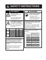
SAFETY INSTRUCTIONS
CAUTION
WARNING
Attach securely protective
earth to the ship's body.
Hazardous voltage.
Can shock, burn or cause
serious injury.
The protective earth
(grounding) is required to the
AC/DC power supply unit to
prevent electrical shock.
Do not work inside the equipment unless totally familiar
with electrical circuits.
Do not approach the antenna
closer than 0.9 m (MPE by
FCC) when it is transmitting.
Confirm that the power supply voltage
is compatible with the voltage rating
of the equipment.
The antenna emits radio waves
which can be harmful to the
human body.
Connection to the wrong power supply
can cause fire or equipment damage.
The voltage rating appears on the label
at the rear of the display unit.
RF power density
Description
Distance
on antenna aperture
required by
100 W/m
FM-8800S
FM-8800D
2
10 W/m
2 W/m 2
100 W/m 2
0.11 m IEC 60945
0.33 m IEC 60945
0.9 m MPE by FCC
0.11 m IEC 60945
10 W/m 2
2 W/m 2
0.33 m IEC 60945
0.9 m MPE by FCC
2
(MPE: Minimum Permissible Exposure)
Turn off the power at the mains switchboard before beginning the installation.
Post a warning sign near the switchboard to indicate that power should not
be applied while the equipment is being
installed.
Electrical shock, serious injury or fire can
result if the power is not turned off or is
applied while the equipment is being
installed.
Observe the compass safe distance to
prevent deviation of a magnetic
compass.
Standard
compass
Steering
compass
FM-8800S
1.45 m
0.90 m
FM-8800D
1.45 m
0.95 m
IF-8810
0.85 m
0.55 m
IF-8820
0.75 m
0.50 m
HS-2003
1.50 m
0.95 m
HS-8800
0.40 m
0.30 m
RB-8800
(W/HS-8800)
1.20 m
0.80 m
1.50 m
1.00 m
0.90 m
0.60 m
RB-8810
(W/HS-8800)
PR-240-CE
i
TABLE OF CONTENTS
SYSTEM CONFIGURATION................................................................................ iii
EQUIPMENT LISTS ........................................................................................... iv
1. MOUNTING ................................................................................................... 1-1
2. CONNECTIONS ............................................................................................ 2-1
3. ASSEMBLING CONSOLE KIT ..................................................................... 3-1
PACKING LISTS ............................................................................................... A-1
OUTLINE DRAWINGS ...................................................................................... D-1
INTERCONNECTION DIAGRAMS ....................................................................S-1
ii
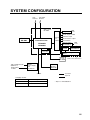
SYSTEM CONFIGURATION
VHF
Antenna
CH 70 RX
Antenna
VHF console
RC-8800
Wing handset MAX
2 sets
T/R AF output for VDR
Handset
HS-2003
Transceiver Unit
Junction
Box*
IF-8810
IEC61162-1 input
DSC information output
External alarm
Remote station
RB-8800/8810
FM-8800D
FM-8800S
DMC I/F
IF-8820
MAX
4 sets
RB-8800/8810
Printer
IF+UTP-80FK
Distress Message Controller
DMC-5
Printer
PP-510
PP-8800
100-115/200-230 VAC
50/60 Hz, 1φ
Radio Battery
24 VDC
AC/DC
Power Supply
Unit
PR-240-CE
Omit for Russian Version
External
Speaker
SEM-21Q
24 VDC
: Standard
: Optional
Category of units
Unit
Category
Antenna
Exposed to weather
All other units
Protected from weather
*: Option for FM-8800S/D-N
iii
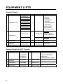
EQUIPMENT LISTS
Standard Supply
Name
1
Transceiver Unit
Type
FM-8800D-E-A
FM-8800D-E-N
FM-8800D-F-A
FM-8800D-F-N
FM-8800S-E-A
FM-8800S-E-N
FM-8800S-F-A
FM-8800S-F-N
FM-8800S-R-A
FM-8800S-R-N
Qty
1
FP05-05700
2
Accessories*
4
5
Junction Box
Installation
Materials*
Spare Parts*
Remarks
D: Duplex
S: Simplex
E: With handset
HS-2003
F: With microphone
DM-2003-F
A: With IF-8810
N: No IF-8810
R: Russian version
—
000-054-228
1
FP05-05710
3
Code No.
000-054-156
IF-8810
1
—
CP05-09900
1
000-054-227
SP05-05501
1
005-377-820
For E-type
Handset HS-2003,
Hanger FP05-05510,
Others FP05-05511
For F-type
Microphone DM-2003-F
For A-type
Power cable 05S9371,
CP05-09901
Standard Supply for VHF Console
1
Name
VHF Console
Type
RC-8800-SN
RC-8800-DN
RC-8800-SA
RC-8800-DA
Qty
1
Code No.
—
2
Installation
Masteries*
CP05-10201
1
005-371-850
3
Accessories*
FP05-05800
1
000-054-372
5
Spare Parts*
SP05-05501
1
005-377-820
Remarks
D: Duplex FM-8800D
S: Simplex DM-8800S
N: No printer
A: With printer & I/F board
Handset HS-2003 &
Handset hanger FP05-05510
*: See lists at the end of this manual.
iv
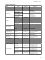
EQUIPMENT LISTS
Optional Equipment
Name
Type
Code No.
Remarks
Flush Mount Kit
OP05-102
Junction Box
IF-8810
—
W/ Screw 5x20 4 pcs.
DMC Interface
IF-8820
RB-8800-15
(W/ 1.5 m Cable)
RB-8800-20
(W/ 2 m Cable)
RB-8810-15
(W/ 1.5 m Cable)
RB-8810-20
(W/ 2 m Cable)
HS-8800-15
—
No use for Russian version
—
·FP05-05701*,
·Handset HS-8800,
·Hanger W/DIST. button HG-8800
—
·FP05-05511*,
·Handset HS-8800,
·Hanger HG-8810
000-054-230
W/ 1.5 m Cable
HS-8800-20
000-054-171
W/ 2 m Cable
HS-8800-W-35
000-054-287
Waterproof
HS-2003-15
000-054-223
W/ Cable 1.5 m
HS-2003-20
000-XXX-XXX
W/ Cable 2.0 m
HS-2003-50S
000-XXX-XXX
W/ Straight cable 5.0 m
HS-6000FZ11
000-135-072
HG-8800
000-054-229
For HS-8800
HG-8810
000-054-231
For HS-8800
FP05-05510
005-951-790
For HS-2003
AP-102
000-580-019
For HS-6000FZ11
Loudspeaker
SEM-21Q
000-144-917
Dynamic Mic. Set
OP05-57
000-045-775
Carbon Mic. Set
OP05-58
000-045-776
Handset set
OP05-42
000-045-778
Mic. Receptacle Box
Microphone
RBD-VHF (B)
000-056-094
DM-2003-F
005-377-760
Printer
PP-510
—
Printer Interface
IF-8500
—
AC-DC Power Supply
PR-240-CE
—
Remote Station
Handset
Handset Hanger
Antenna Material
000-054-120
AP05-00800
000-057-721
AP05-00810
000-057-722
AP05-00900
000-057-739
AP05-01000
000-054-123
Handset HS-6000FZ5,
Receptacle RDB-VHF(B),
Hanger AP-102
Handset HS-6000FZ6,
Receptacle RDB-VHF,
Hanger AP-102
Handset HS-6000FZ11,
Receptacle RDB-VHF(B),
Hanger AP-102
Whip antenna FAB-151D,
Mounting plate 4-310071,
Coax. Cable 5D-2V 10m,
Connector M-P-5 2 PCS
Whip antenna RA106,
Mounting plate RA115,
Coax. Cable 05S9104 5m
Whip antenna 396-1,
Mounting plate 4187
Whip antenna FAB-151D,
Mounting plate 4-310071,
Connector M-P-7 2 PCS
*: See lists at the end of this manual
v
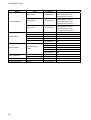
EQUIPMENT LISTS
Name
Antenna Material
Signal Cable
Twisted Cable
VHF Console Kit
Type
AP05-01100
000-054-224
AP05-01200
000-054-232
AP05-01210
000-054-233
05S0309 *10M*
000-106-043
Whip antenna 150M-W2VN,
Coax. Cable 5D-2V 10m,
Connector M-P-5 2 PCS
Whip antenna FAB-151D,
Mounting plate 4-310071,
Coax. Cable 5D-2V 10m,
Connector M-P-5 & M-P-7
Whip antenna FAB-151D,
Mounting plate 4-310071,
Coax. Cable 5D-2V 20m,
Connector M-P-5 & M-P-7
10m
05S0309 *20M*
000-106-044
20m
05S0309 *30M*
000-106-046
30m
05S0309 *40M*
000-106-047
40m
05S0309 *50M*
000-106-048
50m
000-111-680
5m
000-120-792
10m
000-120-793
15m
000-120-794
20m
CO-SPEVV-SB-C
0.2x2P
000-120-214
30m
RC-8800-N-75BG
000-054-125
Without Printer
RC-8800-A-75BG
000-054-126
With Printer
Printer
PP-8800
-
Emergency lamp
EMG-1T
000-138-378
vi
Remarks
Code No.
W/ power cable
For rack console, cable attached
1.
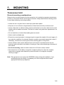
MOUNTING
Transceiver Unit
General mounting considerations
Determine the mounting location for the transceiver unit considering operator convenience,
proximity to the power source and the ground location. Keep these and the following points
in mind when selecting a mounting location.
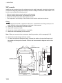
• Locate the unit in a place free of water spray and water splash.
• Keep the unit out of direct sunlight because of heat that can build up inside the unit.
• Leave a little slack in cables to allow a service technician to move the radio from its usual
location with the cables connected. This lets him make tuning and other adjustments on a
“live” set.
• Do not install the unit where flammable gases are stored.
• Select a well-ventilated area.
• Ensure the mounting location is strong enough to support the weight of the unit (approx. 6
kg) under the condition of continued vibration normally encountered aboard the vessel. If
necessary, reinforce the mounting area with a doubling plate or lining block.
• Leave sufficient space at the sides and rear of the unit for maintenance and service
purposes and to provide for circulation of cooling air. See outlines drawings at the back of
this manual.
• For flush mounting, select a location where the LCD can be easily viewed.
• The transceiver unit will affect a magnetic compass if placed too near the compass.
Observe the compass safe distance to prevent deviation of a magnetic compass,
referring to page “ i ”.
Note: Take great care not to press the DISTRESS switch during the installation. If you
accidentally press the switch, immediately turn off the equipment and contact
appropriate authority by telephone.
1-1
1. MOUNTING
Overview of mounting methods
Keep pressed for 4 s in case of DISTRESS.
The alert is transmitted with steady lighting.
DISTRESS
1
2
4 IntCom
GHI
ALM STOP
CALL
Keep pressed for 4 s in case of DISTRESS.
The alert is transmitted with steady lighting.
DISTRESS
1
2
4 IntCom
GHI
ALM STOP
MSG
7
INTL
USA
PQRS
SHIFT
*
CANCEL
CALL
ABC
5
ACK
8
SCAN
0
HI/L0
JKL
TUV
3
6
9
#
TEST
DEF
USA
SHIFT
ABC
5
ACK
8
SCAN
0
HI/L0
JKL
TUV
3
6
9
#
TEST
DEF
PRINT
MNO
DW
WXYZ
LOG
CH16
FILE
MENU
ENT
FILE
MNO
DW
INTL
PQRS
CH16
PRINT
WXYZ
MSG
7
*
CANCEL
MENU
LOG
ENT
Overhead
Tabletop
Keep pressed for 4 s in case of DISTRESS.
The alert is transmitted with steady lighting.
DISTRESS
1
2
4 IntCom
GHI
7
ALM STOP
CALL
MSG
Flush Mount
INTL
USA
PQRS
SHIFT
*
CANCEL
ABC
5
ACK
8
SCAN
0
HI/L0
JKL
TUV
3
6
9
#
TEST
DEF
PRINT
MNO
DW
WXYZ
LOG
CH16
FILE
MENU
ENT
Bulkhead
Overview of mounting methods
1-2
1. MOUNTING
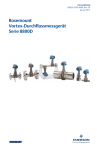
Mounting procedure for tabletop, overhead and bulkhead mounting
1. Using the hanger as a template, mark fixing holes in the mounting location.
2. Fix the hanger to the mounting location with self-tapping screws and washers (supplied).
(For added support, use nuts, bolts and washers instead of self-tapping screws.)
3. Screw the knob bolts with washers into the transceiver unit.
4. Set the transceiver unit to the hanger and tighten knob bolts.
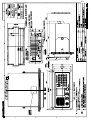
265
251
Keep pressed for 4 s in case of DISTRESS.
The alert is transmitted with steady lighting.
1
DISTRESS
110
2
ABC
3 TEST
DEF
4 IntCom
5 ACK
6 PRINT
INTL
8 SCAN
9 DW
0 HI/L0
#
GHI
JKL
MNO
CH16
FILE
ALARM
CANCEL
7
ALM STOP
SQL
VOL/PWR
CH
CALL
SHIFT
MSG
OFF
TUV
*
HANDSET
USA
PQRS
WXYZ
LOG
MENU
ENT
PUSH TO ENTER
AUTO
Keep pressed for 4 s in case of DISTRESS.
The alert is transmitted with steady lighting.
DISTRESS
1
2
4 IntCom
GHI
ABC
5
ACK
8
SCAN
0
HI/L0
JKL
3
6
TEST
DEF
PRINT
MNO
CH16
FILE
ALARM
7
ALM STOP
HANDSET
SQL
VOL/PWR
CH
CALL
MSG
OFF
AUTO
INTL
USA
PQRS
SHIFT
*
100
CANCEL
TUV
9
#
DW
WXYZ
LOG
MENU
100
ENT
PUSH TO ENTER
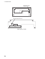
• All dimensions in millimeters.
• Leave sufficient space at the sides and rear of the unit to provide easy access for
maintenance and service.
Mounting dimensions for tabletop, overhead and bulkhead mounting
1-3
1. MOUNTING
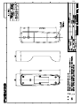
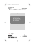
Mounting procedure for flush mount (option)
Requires optional flush mount kit OP05-102 (Code No. 000-054-120). Prepare a cutout in
the mounting location whose dimensions are as shown in the figure below.
Flush mount kit OP05-102
Name
1 Mounting plate
2 Self-tapping screw
3 Hex screw
Code No.
100-323-160
000-802-081
000-882-075
Qty
1
4
2
#150
251
260 ± 1
280 ± 1
277 ± 0.5
122 ± 0.5
244
105 ± 1
30 ± 1
20
14 27
Type
05-093-1211
5x20
M8x16
Pilot holes (4 pcs.)
Mounting dimensions for flush mount
VHF Antenna
The antenna requirements
Any good quality antenna meeting the requirements shown below may be used. A high-gain
antenna is preferable.
• Frequency range:
155 to 164 MHz
• Impedance:
50 ohms
• Polarization:
Vertical
• Handling power:
30 W/ min
• Quality:
Able to withstand marine environment
Mounting considerations
• The antenna should be well separated from nearby antennas, masts, and other interfering
objects.
• The higher the antenna is mounted above the horizon, the further the communications
range.
Mounting procedure
The basic mounting procedure for antennas supplied by FURUNO is as follows, however
consult appropriate outline drawing for details.
1. Fasten the antenna bracket to the stanchion.
2. Set the antenna to the antenna bracket and tighten bolts.
3. Screw the coaxial cable plug into the antenna.
1-4
1. MOUNTING
CH70 RX Antenna
The antenna should be well separated from nearby antennas, masts, and other interfering
objects.
The mounting procedure is the same as that for the VHF antenna, however consult
appropriate outline drawing for details.
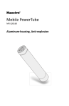
Handset Hanger
The handset hanger can be mounted at the left side of the transceiver unit. The mounting
location should provide easy access to front panel controls while operating the handset.
Also, the length of the standard handset cable is 50 cm, so locate the handset hanger within
50 cm of the unit. (Longer cables are available optionally.)
Power Supply (option)
For Convention vessels, both AC and DC power must be fed to the FM-8800D/8800S, via
an AC/DC power supply. When AC input fails, DC power is supplied. FURUNO can supply
an AC/DC power supply unit, the PR-240-CE.
Mounting considerations
When selecting a mounting location, keep in mind the following points.
• Select a location which provides adequate ventilation.
• The location must be clean and dry.
• The mounting location must be able to support the weight of the unit (14.5 kg) under the
continued conditions of vibration normally encountered aboard the vessel. If necessary,
reinforce the mounting location.
• The PR-240-CE will affect a magnetic compass if it is placed to near the compass.
Observe the compass safe distance to prevent deviation of a magnetic compass,
referring to page “ i ”.
Mounting
Refer to outline drawing.
1-5
1. MOUNTING
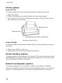
Printer (option)
Printer PP-510
To mount the printer, refer to the printer outline drawing at the back of this manual.
1. Select a flat surface.
2. Fix the mounting base to the mounting location with four screws (supplied).
3. Lay the printer on the top of the mounting base and fasten it with the mounting fixtures
(two at each side and one at rear).
Mounting Fixture
Mounting Fixture
Mounting Dimensions 300 (H) x 396 (W) mm
Mounting of Printer PP-510
Printer PP-8800
The printer PP-8800 is flush-mounted in a panel. Refer to the outline drawing at the back of
this manual.
1. Make a cutout of 208(w) x 118(h) mm.
2. Set the printer and fix it with four self-tapping screws (4x16).
Printer Interface (option)
The printer interface IF-8500 is required for the printer PP-510 which is commonly used with
the FM-8800D/S and other MF/HF radio communication equipment. To mount the unit, see
the outline drawing at the back of this manual.
External Loudspeaker (option)
The external loudspeaker can be installed on a tabletop, the overhead or a bulkhead.
Fasten the loudspeaker to the mounting location with self-tapping screws, or nuts, bolts and
washers. For mounting dimensions, see the outline drawing at the back of this manual.
1-6
1. MOUNTING
Junction box IF-8810/ DMC interface IF-8820
Note: DMC interface IF-8820 is not used for Russian version.
To install the remote box RB-8800/RB-8810, wing handset, etc., the junction box IF-8810 is
required. Install the junction box near the transceiver unit. Approx. 3 m cable is preattached
to the junction box to connect to the transceiver unit.
To connect Furuno’s distress message controller DMC-5, the DMC interface IF-8820
(option) is required.
1. Open the cover.
2. Mount the unit with four self-tapping screws (5x20).
240
100
Note: This plug is not
fitted in IF-8820.
Fixing holes 5mm dia.
Mounting the junction box/DMC interface
1-7
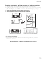
1. MOUNTING
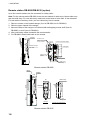
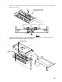
Remote station RB-8800/RB-8810 (option)
Up to four remote stations can be connected in a daisy chain.
Note: For the remote station RB-8800, there are two method of cable entry: bottom-side entry
and rear-side entry. For rear-side entry, make one or two holes of more than 12 mm diameter.
For last station in the daisy chain, just one cable entry hole is needed.
1. Remove screws on the handset hanger (four for RB-8800, six for RB-8810).
2. Remove upper chassis of the hanger.
3. Mount the base of the hanger to a bulkhead with self-tapping screws 4x20 (four for
RB-8800), or 4x16 (two for RB-8810).
4. After connecting cables, assemble the remote station.
5. For RB-8800, attach blind seals on the screws.
Cover of handset hanger
63
Handset hanger
HG-8800
20 30
33
Screws 4 pcs.
Attach blind seal
on the screws.
40
Nameplate
DISTRESS
Cable entry
(Rear)
140± 0.5
φ 12
Handset
HS-8800
φ 12
Cable entry
77
VOLUME
#150
4- φ4.5
Fixing holes
40 ± 0.5 40 ± 0.5
Cable entry
(Bottom)
Remote station RB-8800
Hanger
HG-8810
(77)
Handset
HS-8800
57
22
145 ± 0.5
208
(208)
#150
φ12, Cable entry
Nameplate
2- φ4.5
Fixing hole
Hanger
Hanger mounting base
Remote station RB-8810
1-8
42
Cable entry
65
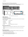
1. MOUNTING
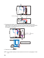
Outdoor mounting of RB-8810
Remote station RB-8810 with waterproof-type handset HS-8800-W-35 can be mounted
outdoors. The hanger should be coated as directed below with silicone sealant for
waterproofness.
1. Fix the mounting base with self-tapping screws. Coat exposed part of these screws with
silicone sealant.
2. Attach the cable from the transceiver unit or junction box. Coat cable around cable
entrance with silicone sealant
3. Fix the cover of the handset hanger. Coat junction between mounting base and cover
with silicone sealant.
2. All around the cable
at cable entry
Self-tapping screws
3. All around the junction
coating parts
Note: Confirm that plastic washers are
in screw holes before fixing cover.
1-9
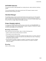
1. MOUNTING
VHF console
Install the rack console where the equipment can be easily operated, checked and serviced.
Consult with shipyard personnel and ship's officer-in-charge to determine best location. The
location must satisfy the following points:
• Select a location where controls can be easily operated.
• Select a location where shock and vibration are minimal.
• Locate the console away from water splash and rain.
• The temperature and humidity of the location should be both stable and moderate.
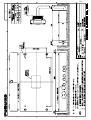
Fixing
1. Ask shipyard personnel to tighten six M5 nuts or six M5 bolts to the fixing holes (on the
wall), referring to the outline drawing at the back of this manual.
2. Detach the cover assembly from the console.
3. Hang VHF console on bolts.
4. Screw the console with the bolts or nuts tightly.
5. Attach the cover assembly to the console.
Note: When you connect wires as soon as attaching console, refer to paragragh 2-10.
6. Attach the handset hanger with two screws.
7. To attach the optional emergency lamp, connect the cable to the terminal board, and
then attach the lamp to the console. Refer to the interconnection diagram and out line
drawing.
(371)
EMG-1T
EMERGENCY LAMP
190
°
75
(371)
330
145
480
(500)
30
298 ± 0.5
1-10
FIXING HOLES
TERMINAL BOARD
(266)
#50
CABLE ENTRY
(REAR)
250
30
40
170 ± 0.5
170 ± 0.5
40
HANDSET HANGER
2.
CONNECTIONS
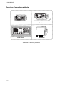
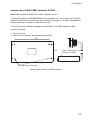
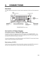
Overview
The figure below shows where to connect various equipment at the rear of the transceiver
unit.
ANT
Connects antenna.
Ground terminal.
24VDC
Connects power
cable.
PRINTER
Connects printer
PP-510.
IEC61162-1 (NMEA)/REMOTE
Connects junction box IF-8810.
EXT SP
Connects external
loudspeaker.
CH70 RX ANT
Connects DSC
antenna here.
FM-8800D/8800S, rear view
Connection of Power Supply
Convention vessels, 100/220 VAC ship’s mains
Convention vessels must supply both AC and DC power to the FM-8800D/8800S, via an
AC/DC power supply unit. Both AC and DC are supplied by the AC/DC power supply unit,
and when AC input fails DC power is activated.
Connect the radio battery to the DC IN terminal on the PR-240-CE. Connect the AC ship’s
mains to the AC IN terminal on the PR-240-CE.
Radio battery (24 VDC)
Attach the connector supplied to the power cable and plug it into the 24VDC connector at
the rear of the transceiver unit. Connect the wire ends to the radio battery line.
2-1
2. CONNECTIONS
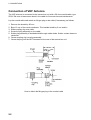
Connection of VHF Antenna
The VHF antenna is connected to the transceiver unit with a 50 ohm coaxial cable, type
5D-2V. Be sure to leave some slack in the cable for future service and maintenance.
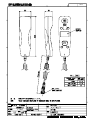
Lay the coaxial cable and attach an M-type plug to the cable (if necessary) as follows.
1.
2.
3.
4.
5.
Remove the sheath by 20 mm.
Bare 13 mm of the center conductor. Trim braided shield by 5 mm and tin.
Slide coupling ring onto cable.
Screw the plug assembly on the cable.
Solder plug assembly to braided shield through solder holes. Solder contact sleeve to
conductor.
6. Screw coupling ring into plug assembly.
7. Screw the plug into the ANT connector at the rear of the transceiver unit.
How to attach the M-type plug to the coaxial cable
2-2
2. CONNECTIONS
Connection of DSC Antenna
The DSC antenna is connected to the transceiver unit with a 50 ohm coaxial cable, type
5D-2V. Attach an M-type plug to the cable (if necessary) as shown an page 2-2. Screw the
plug into the CH70 RX ANT connector at the rear of the transceiver unit.
Connection of Handset
Connect the handset cable to the HANDSET connector on the front panel.
Grounding the Transceiver Unit
Fasten a ground wire (local supply) between the GND terminal at the rear of the transceiver
unit and ship’s hull (or ground bus).
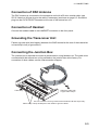
Connecting the Junction Box
The junction box is required to connect a remote station, wing handset, etc. The cable to be
connected with the transceiver unit is prefitted on the junction box at the factory. For
connection of other cables, see the interconnection diagram.
Cable entry
Clamp the cable with
U-type cable clamps.
Use one of these nuts for ground terminal between JB and ship's body.
Cable clamp: Clamp shield part of the cables to ground cables.
2-3
2. CONNECTIONS
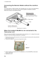
Connecting the Remote Station without the Junction
Box
The remote station (or DMC Interface, Mic. Receptacle box, etc) can be connected directly
to the transceiver unit, using the D-sub connector supplied as installation materials.
Attach the connector to the cable as follows.
Shield tape (metal)
Fold back the armor,
and then wind the shield
tape along the edge of cable.
Cable clamp
Cable
Connector XM2A-3701 &
Housing case XM2S-3712
Attachment of connector
When the handset HS-2003 is not connected to the
Transceiver unit
When the handset HS-2003 is not connected to the transceiver unit, i.e.,always the remoted
handset is used, the following modification is necessary.
1. Dismount the cover of the transceiver unit by removing four screws at the rear panel and
two screws at the side.
2. Dismount the bottom cover by removing seven screws.
J15
CPU board
05P0773
3. Shorten between #1 and #2 of J15. The handset line of the HANDSET port becomes
always “ON HOOK”.
4. Assemble the unit.
2-4
2. CONNECTIONS
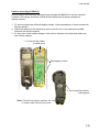
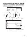
Connection of AC/DC Power Supply Unit PR-240-CE
The power supply PR-240-CE is shipped ready for connection to a 200-230 VAC ship’s
mains. If the ship’s mains is 100 VAC – 115 VAC, change the tap connection and terminal
board connection as below. Attach label supplied as accessories to the punch mark in the
front panel according to the ship’s mains.
Ship’s mains
Tap connection
Terminal board
connection #1 & #2
100-115 VAC
SEL 115 V
b
200-230 VAC
SEL 230 V
a
100-115 VAC
200-230 VAC
1
White
1
White
2
Black
2
Black
3
3
Punch mark
(a)
(b)
Front
SEL
115 V
1
2
3
4
5
6
7
8
SEL
230 V
Terminal board connection
Heat sink
Tap connection (Pull out to disconnect)
Top view of AC/DC power supply unit (cover removed)
2-5
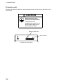
2. CONNECTIONS
Protective earth
Connect IV-2.0sq wire between ship’s superstructure and the ground terminal on the
PR-240-CE.
CAUTION
Attach protective earth
securely to the ship's body.
The protective earth
(grounding) is required for the
AC/DC power supply unit to
prevent electrical shock.
Attach a label here.
GND terminal
PR-240-CE Front panel
2-6
2. CONNECTIONS
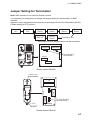
Jumper Setting for Termination
Note: DMC interface is not used for Russian version.
It is necessary, for termination, to change the jumper setting for remote station or DMC
interface.
Open the unit(s) terminated and change the jumper plugs J2 and J3 to ON position (#2-#3).
(Default setting is OFF position.)
Transceiver
Unit
Junction
Box
Remote
Station
Remote
Station
DMC I/F
Remote
Station
Remote
Station
Remote
Station
Terminated Unit
Note that up to four remote stations can be connected.
LINE
TERMINATION
J3
DISTRESS
1
ON
RS-485
TERMINATION
J2
3
1
ON
3
J1
Set to ON (#2-3)
for termination.
05P0782
TB1
VOLUME
TB2
Remote station RB-8800
Cable entry
TB1
TB2
J3
3
3
ON OFF
1 J2
RS-485
TERMINATION
LINE
TERMINATION
ON OFF
1
05P0798
2- φ 4.5
Set to ON (#2-3)
for termination.
J1
Fixing hole
Remote station RB-8810
2-7
2. CONNECTIONS
Remove four screws
to open the unit.
Set jumper plug to ON (#1-2).
05P0778
J4
ON
RS-485
TERMINATION
TB1
DMC Interface IF-8820
2-8
2. CONNECTIONS
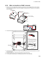
2.10
Wire connection of VHF console
1. Remove the cover assembly and printer assembly (or concealing lid) form the console.
For the printer assembly, remove the cables connected at the Transceiver Unit and the
terminal board.
Cover assembly
Binding screw F
M4X10 8 places
Binding screw F
M4X10 4 places
Printer assembly
or Concealing lid
Console
Terminal board
2. Connect the power cable from the ship to the terminal block 1 (+) and 2 (-).
Terminal Board Wiring
1. Wiring conductor
9∼10mm
2. Wiring
1)Insert a screwdriver which blade edge
is 3.5 X 0.5mm to the square hole.
2)Press the screwdriver to arrow direction
to open the spring in the round hole.
3)Insert the wire to the round hole.
4)Remove the screwdriver.
Power cable
from the ship
1 2
1 2 3 4 5 6 7 8
-
Square hole
Round hole
Terminal board
3. Connect the ground wire from ship to each ground terminal for the transceiver unit and
the junction box.
4. Connect cables from external equipments to the junction box.
5. Fix the printer assembly (or concealing lid) and the cover assembly.
2-9
2. CONNECTIONS
This page is intentionally left blank.
2-10
3.
ASSEMBLING CONSOLE KIT
A VHF console kit is required to mount the Transceiver Unit in the field. There are two types
as shown below.
VHF console kit
Type
RC-8800-N-75BG
RC-8800-A-75BG
Code No.
000-054-125
000-054-126
Remarks
Without printer
With printer
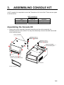
Assembling the Console Kit
1. Remove the cover assembly, the panel assembly and the printer assembly (or
concealing lid) from the console. For the printer assembly, remove the cable connected
to the terminal board.
Cover assembly
Binding screw F
M4X10
8 places
Binding screw F
M4X10
4 places
Printer assembly
(or Concealing lid
#
#
Remove screws( )and
detach the panel assembly.
Console
Panel assembly
3-1
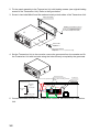
2. Fix the panel assembly to the Transceiver Unit with binding screws (use original binding
screws of the Transceiver Unit). Refer to the figure below.
3. Screw in hex bolts M8x16 and flat washers loosely at both sides of the Transceiver Unit.
Panel assembly
Binding screw M4 2 places
(Use the original screws
of the Transceiver Unit.)
Washer M8
2 places
Hex bolt M8X16
2 places
(faster loosely)
4. Set the Transceiver Unit to the console, remove the grommets from the console and fix
the Transceiver Unit with hex bolts using the holes formerly occupied by the grommets.
Hex head screws
Mounting of
the Transceiver Unit
Insert console upside down. Close the hole with grommets
lastly.
Connecter
Connecter
Mounting
plate
Transceiver
Unit
Flat washer
Fix Mounting Plate
between washers.
5. Connect connector from the fuse to the power connector derived from the Transceiver
Unit.
3-2
6. Replace the cable attached to junction box with the cable (55 cm, 37-pin D sub) supplied
with the console kit.
Replace the original cable
with the cable assembly
DSUB37M-PHX3-L550.
A
Junction box
(without cover)
PH Connector
10P
PH Connector
12P
J3
J2
J1
PH Connector
14P
2
3
Crimp-on lug
A View
7. Connect the cable (37-pin D sub) attached to the junction box to the Transceiver Unit
and then mount the junction box on the console.
±Binding screw F
M4X8 4 places
Cover
±Screw B
M4X10 4 places
Mounting plate
3-3
Junction box
Grommets 2 places
8. For the console w/printer, connect the printer cable for data transmission to the
PRINTER port of the Transceiver Unit and fix the power cable to the terminal board as
before. Then, fix the printer assembly to the console. For no printer, fasten the
concealing lid to the console.
Printer
Printer cable
W/ Printer
J2
Insert the mounting plate
for printer to the catch of the console
View
9. Fasten the cover assembly.
NOTE: If the console assembly is to be mounted on the hull, refer to paragraghs 1-9 and
2-10.
3-4
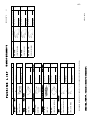
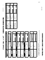
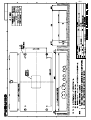
OUTLINE
INSTALLATION MATERIALS
ACCESSORIES
SPARE PARTS
UNIT
005-377-800
000-151-711
CP05-09901
05S9371-0
005-951-920
005-951-790
FP05-05511
000-054-223
FP05-05510
HS-2003
005-377-820
SP05-05501
1
Q'TY
1
1
CP05-09900
1
1
1
FP05-05700
1
SP05-05501
000-054-225 **
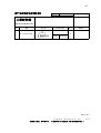
FM-8800S/D
DESCRIPTION/CODE №
(略図の寸法は、参考値です。 DIMENSIONS IN DRAWING FOR REFERENCE ONLY.)
DOCUMENT
DISTRESS PROCEDURE
遭難通信要領書
OPERATOR'S MANUAL
取扱説明書
INSTALLATION MANUAL
装備要領書
OPERATOR'S GUIDE
VHF/MF DISTRESS ALERT
FLOW
操作要領書
遭難警報フロVHFMF*
図書
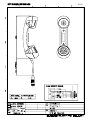
NAME
FM-8800S-J/E-N/FM-8800D-J/E-N
コ-ド番号末尾の[**]は、選択品の代表型式/コードを表します。
CODE NUMBER ENDING WITH "**" INDICATES THE CODE NUMBER OF REPRESENTATIVE MATERIAL.
INSTALLATION MATERIALS
工事材料
CABLE ASSY.
ケーブル組品
工事材料
ACCESSORIES
付属品
BRACKET FOR HANDSET
ハンドセットハンガー組品
HANDSET
ハンドセット
付属品
SPARE PARTS
予備品
予備品
TRANSCEIVER UNIT
送受信機
ユニット
NAME
PACKING LIST
OUTLINE
000-149-935
000-149-930 **
TIC-56420-*
000-149-932 **
OM*-56420-*
000-149-934 **
IM*-56420-*
000-809-270
OS*-56420-*
*52-00101-*
1
1
1
1
1
Q'TY
1/1
05EC-X-9851
DESCRIPTION/CODE №
05EC-X-9851 -4
A-1
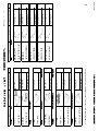
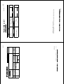
NAME
OUTLINE
INSTALLATION MATERIALS
ACCESSORIES
SPARE PARTS
UNIT
005-377-800
CP05-09901
000-054-223
005-951-790
HS-2003
005-951-920
FP05-05510
FP05-05511
005-377-820
SP05-05501
000-054-219
1
1
1
Q'TY
1
CP05-09900
1
1
1
FP05-05700
000-054-166 **
IF-8810
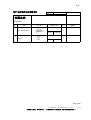
FM-8800S*/D*
DESCRIPTION/CODE №
(略図の寸法は、参考値です。 DIMENSIONS IN DRAWING FOR REFERENCE ONLY.)
DOCUMENT
INSTALLATION MANUAL
装備要領書
OPERATOR'S MANUAL
取扱説明書
OPERATOR'S GUIDE
操作要領書
DISTRESS PROCEDURE
VHF/MF DISTRESS ALERT
FLOW
遭難通信要領書
遭難警報フロVHFMF*
図書
OUTLINE
INSTALLATION MATERIALS
INSTALLATION MATERIALS
工事材料
工事材料
CABLE ASSY.
ケーブル組品
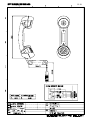
NAME
FM-8800S-J/E-A/FM-8800D-J/E-A、FM-8800S-J/E-AHK/FM-8800D-J/E-A-HK
コ-ド番号末尾の[**]は、選択品の代表コードを表します。
CODE NUMBER ENDING WITH "**" INDICATES THE CODE NUMBER OF REPRESENTATIVE MATERIAL.
INSTALLATION MATERIALS
工事材料
工事材料
HANDSET
ハンドセット
BRACKET FOR HANDSET
ハンドセットハンガー組品
ACCESSORIES
付属品
付属品
SPARE PARTS
予備品
予備品
JUNCTION BOX
セツゾクバコ
TRANSCEIVER UNIT
送受信機
ユニット
PACKING LIST
1/1
1
Q'TY
000-149-932 **
000-149-930 **
IM*-56420-*
000-149-934 **
OM*-56420-*
1
1
1
1
1
1
CP05-08701
000-149-935 **
OS*-56420-*
000-809-270
TIC-56420-*
*52-00101-*
005-949-280
CP05-08701
000-151-711
05S9371-0
DESCRIPTION/CODE №
05EC-X-9856 -3
05EC-X-9856
A-2
DOCUMENT
000-149-932
000-809-270
IM*-56420-*
*52-00101-*
005-377-800
000-151-711
CP05-09901
05S9371-0
005-377-760
DM-2003-F
005-377-820
SP05-05501
000-054-225 **
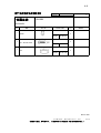
FM-8800S/D
1
1
Q'TY
1
1
1
1
CP05-09900
1
FP05-05710
DESCRIPTION/CODE №
(略図の寸法は、参考値です。 DIMENSIONS IN DRAWING FOR REFERENCE ONLY.)
DISTRESS PROCEDURE
遭難通信要領書
OPERATOR'S GUIDE
操作要領書
OPERATOR'S MANUAL
取扱説明書
NAME
FM-8800S-F-N/FM-8800D-F-N
CODE NUMBER ENDING WITH "**" INDICATES THE CODE NUMBER OF REPRESENTATIVE MATERIAL.
INSTALLATION MANUAL
装備要領書
VHF/MF DISTRESS ALERT FLOW
遭難警報フロVHFMF*
図書
OUTLINE
INSTALLATION MATERIALS
ACCESSORIES
SPARE PARTS
UNIT
INSTALLATION MATERIALS
工事材料
CABLE ASSY.
ケーブル組品
工事材料
MICROPHONE
マイクロフォン箱詰品
付属品
SPARE PARTS
予備品
予備品
TRANSCEIVER UNIT
送受信機
ユニット
NAME
PACKING LIST
OUTLINE
05EC-X-9858
000-149-935
000-149-934
TIC-56420-*
000-149-930
OS*-56420-*
OM*-56420-*
DESCRIPTION/CODE №
05EC-X-9858 -2
1/1
1
1
1
Q'TY
A-3
NAME
INSTALLATION MATERIALS
005-949-280
CP05-08701
005-377-800
000-151-711
CP05-09901
05S9371-0
005-377-760
DM-2003-F
005-377-820
SP05-05501
1
1
1
Q'TY
1
1
1
CP05-09900
1
FP05-05710
000-054-225 **
000-054-219
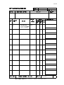
FM-8800S/D
IF-8810
DESCRIPTION/CODE №
(略図の寸法は、参考値です。 DIMENSIONS IN DRAWING FOR REFERENCE ONLY.)
NAME
DOCUMENT
DISTRESS PROCEDURE
遭難通信要領書
OPERATOR'S GUIDE
操作要領書
OPERATOR'S MANUAL
取扱説明書
INSTALLATION MANUAL
VHF/MF DISTRESS ALERT
FLOW
装備要領書
遭難警報フロVHFMF*
図書
FM-8800S-F-A/FM-8800D-F-A
CODE NUMBER ENDING WITH "**" INDICATES THE CODE NUMBER OF REPRESENTATIVE MATERIAL.
INSTALLATION MATERIALS
工事材料
工事材料
OUTLINE
INSTALLATION MATERIALS
ACCESSORIES
SPARE PARTS
UNIT
INSTALLATION MATERIALS
工事材料
CABLE ASSY.
ケーブル組品
工事材料
MICROPHONE
マイクロフォン箱詰品
付属品
SPARE PARTS
予備品
予備品
TRANSCEIVER UNIT
送受信機
JUNCTION BOX
セツゾクバコ
ユニット
PACKING LIST
OUTLINE
1/1
000-149-935
000-149-934
TIC-56420-*
000-149-930
OS*-56420-*
000-149-932
OM*-56420-*
000-809-270
IM*-56420-*
*52-00101-*
1
1
1
1
1
Q'TY
05EC-X-9859
DESCRIPTION/CODE №
05EC-X-9859 -2
A-4
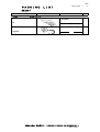
A-5
PACKING LIST
05EC-X-9857 -1
1/1
DM-2003-F
N A M E
マイクセット
O U T L I N E
DESCRIPTION/CODE №
Q'TY
MICROPHONE SET
ZIRXXCDM002
フック
1
HOOK
000-150-017
KON-003
マイクロフォン
1
MICROPHONE
000-150-016
(略図の寸法は、参考値です。
DIMENSIONS IN DRAWING FOR REFERENCE ONLY.)
05EC-X-9857
A-6
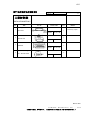
CODE NO.
005-377-800
TYPE
CP05-09901
05EC-X-9401 -2
1/1
工事材料表
INSTALLATION MATERIALS
番 号
NO.
名 称
NAME
型名/規格
DESCRIPTIONS
1
CABLE ASSY.
CODE NO.
1
000-145-423
XM2A-3701
コネクタ(XM2)
1
CONNECTOR
CODE NO.
+トラスタッピンネジ 1種
4
Used only Japan
000-151-748
HOUSING CASE
CODE NO.
3
用途/備考
REMARKS
XM2S-3712
コネクタフード(XM2)
2
数量
Q'TY
L-420
ミニピン組品(1)
1
略 図
OUTLINE
000-145-424
6X20 SUS304
5
SELF-TAPPING SCREW
CODE NO.
000-802-084
05EC-X-9401
FURUNO ELECTRIC CO .,LTD.
(略図の寸法は、参考値です。 DIMENSIONS IN DRAWING FOR REFERENCE ONLY.)
A-7
CODE NO.
005-949-280
TYPE
CP05-08701
05DY-X-9417 -0
1/1
工事材料表
INSTALLATION MATERIALS
番 号
NO.
名 称
NAME
+トラスタッピンネジ 1種
1
略 図
OUTLINE
型名/規格
DESCRIPTIONS
数量
Q'TY
用途/備考
REMARKS
5X20 SUS304
4
SELF-TAPPING SCREW
CODE NO.
000-802-081
05DY-X-9417
FURUNO ELECTRIC CO .,LTD.
(略図の寸法は、参考値です。 DIMENSIONS IN DRAWING FOR REFERENCE ONLY.)
A-8
CODE NO.
005-951-920
TYPE
FP05-05511
05DZ-X-9502 -0
1/1
付属品表
ACCESSORIES
名 称
NAME
番 号
NO.
CODE NO.
2
用途/備考
REMARKS
2
SELF-TAPPING SCREW
ポリカワッシャー
数量
Q'TY
4X16 SUS304 1シュ
+トラスタッピンネジ
1
型名/規格
DESCRIPTIONS
略 図
OUTLINE
000-802-080
M4
2
WASHER
CODE NO.
000-864-937
05DZ-X-9502
FURUNO ELECTRIC CO .,LTD.
(略図の寸法は、参考値です。 DIMENSIONS IN DRAWING FOR REFERENCE ONLY.)
A-9
付属品表
CODE NO.
005-959-720
TYPE
FP05-05701
05EC-X-9502 -2
1/1
RB-8800
ACCESSORIES
名 称
NAME
番 号
NO.
4
SELF-TAPPING SCREW
CODE NO.
3
000-864-937
4X20 SUS304
+トラスタッピンネジ
ブラインドシール
用途/備考
REMARKS
4
WASHER
CODE NO.
2
数量
Q'TY
M4
ポリカワッシャー
1
型名/規格
DESCRIPTIONS
略 図
OUTLINE
000-805-687
05-086-1102-2
4
SEAL
CODE NO.
100-281-282
05EC-X-9502
FURUNO ELECTRIC CO .,LTD.
(略図の寸法は、参考値です。 DIMENSIONS IN DRAWING FOR REFERENCE ONLY.)
A-10
NAME OF
PART
OUTLINE
ヒューズ
1
005-377-820
TYPE
SP05-05501
SPARE PARTS LIST FOR
SHIP NO.
ITEM
NO.
CODE NO.
U
DWG. NO.
OR
TYPE NO.
S
05EC-X-9301 -0 1/1
BOX NO.
P
SETS PER
VESSEL
E
QUANTITY
REMARKS/CODE NO.
WORKING
PER
SET
PER
VES
FGBO 15A
AC125V
SPARE
2
FUSE
000-549-014
MFR'S NAME
FURUNO
ELECTRIC
CO.,LTD.
DWG NO.
05EC-X-9301
(略図の寸法は、参考値です。 DIMENSIONS IN DRAWING FOR REFERENCE ONLY.)
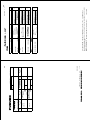
1/1
DOCUMENT
000-149-932 **
000-809-270 **
IM*-56420-*
*52-00101-*
005-371-850
CP05-10201
000-054-223
005-951-790
HS-2003
FP05-05510
005-377-820
SP05-05501
000-054-240 **
1
1
Q'TY
1
1
1
1
1
FP05-05800
RC-8800S/D-N-75BG,RC8800S/D-A-75BG
DESCRIPTION/CODE №
(略図の寸法は、参考値です。 DIMENSIONS IN DRAWING FOR REFERENCE ONLY.)
DISTRESS PROCEDURE
遭難通信要領書
OPERATOR'S GUIDE
操作要領書
OPERATOR'S MANUAL
取扱説明書
NAME
OUTLINE
RC-8800S/D-N-75BG、RC-8800S/D-A-75BG
コ-ド番号末尾の[**]は、選択品の代表コードを表します。
CODE NUMBER ENDING WITH "**" INDICATES THE CODE NUMBER OF REPRESENTATIVE MATERIAL.
INSTALLATION MANUAL
装備要領書
VHF/MF DISTRESS ALERT FLOW
遭難警報フロVHFMF*
図書
OUTLINE
INSTALLATION MATERIALS
ACCESSORIES
SPARE PARTS
UNIT
INSTALLATION MATERIALS
工事材料
工事材料
HANDSET
ハンドセット
BRACKET FOR HANDSET
ハンドセットハンガー組品
付属品
SPARE PARTS
予備品
予備品
VHF CONSOLE
VHFコンソール
ユニット
NAME
PACKING LIST
05EC-X-9861
000-149-935
000-149-934 **
TIC-56420-*
000-149-930 **
OS*-56420-*
OM*-56420-*
DESCRIPTION/CODE №
05EC-X-9861 -0
1/1
1
1
1
Q'TY
A-11
1
番 号
NO.
CABLE ASSY.
ミニピン組品(1)
略 図
OUTLINE
CODE NO.
L-420
000-151-748
型名/規格
DESCRIPTIONS
CP05-10201
TYPE
1
数量
Q'TY
1/1
05EC-X-9409
Used only Japan
用途/備考
REMARKS
05EC-X-9409 -0
FURUNO ELECTRIC CO .,LTD.
(略図の寸法は、参考値です。 DIMENSIONS IN DRAWING FOR REFERENCE ONLY.)
名 称
NAME
INSTALLATION MATERIALS
工事材料表
005-371-850
CODE NO.
A-12
N A M E
O U T L I N E
INSTALLATION MATERIALS
UNIT
005-371-670
CP05-10001
005-371-650 **
RC-8800-N
DESCRIPTION/CODE №
05EC-X-9860 -0
(略図の寸法は、参考値です。
05EC-X-9860
DIMENSIONS IN DRAWING FOR REFERENCE ONLY.)
コ-ド番号末尾の[**]は、選択品の代表コー ドを表します。
CODE NUMBER ENDING WITH "**" INDICATES THE CODE NUMBER OF REPRESENTATIVE MATERIAL.
INSTALLATION MATERIALS
工事材料
工事材料
CONSOLE KIT
コンソール組品
ユニット
RC-8800-N/RC-8800-A
PACKING LIST
1
1
Q'TY
1/1
A-13
⇟ภ
01
%#$.'#55;
㩚㩐㩕㩩㩧⚵ຠ
%#$.'#55;
㩃㨺㩖㩨㩣⚵ຠ
⇛ޓޓ࿑
176.+0'
%1&'01
.
%1&'01
&57$/2*:.
ဳฬ㧛ⷙᩰ
&'5%4+26+105
%2
6;2'
ᢙ㊂
36;
'%:
↪ㅜ㧛⠨
4'/#4-5
'%: 㧲㨁㧾㨁㧺㧻ޓ㧱㧸㧱㧯㨀㧾㧵㧯ޓ㧯㧻ޓ㧚㧘㧸㨀㧰
㧔⇛࿑ߩኸᴺߪޔෳ⠨୯ߢߔ&ޓޕ+/'05+105+0&4#9+0)(144'('4'0%'10.;㧕
ฬޓޓ⒓
0#/'
+056#..#6+10/#6'4+#.5
Ꮏ᧚ᢱ
%1&'01
A-14
0#/'
&1%7/'06
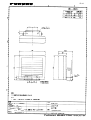
%)
8%6(:%/
,'
%2
22
&'5%4+26+10%1&'ͳ
'%: 䋨⇛࿑䈱ኸᴺ䈲䇮ෳ⠨୯䈪䈜䇯㩷㩷㪛㪠㪤㪜㪥㪪㪠㪦㪥㪪㩷㪠㪥㩷㪛㪩㪘㪮㪠㪥㪞㩷㪝㪦㪩㩷㪩㪜㪝㪜㪩㪜㪥㪚㪜㩷㪦㪥㪣㪰㪅䋩
'%:
A-15
36;
㪫㪮㪦㩷㪫㪰㪧㪜㪪㩷㪘㪥㪛㩷㪚㪦㪛㪜㪪㩷㪤㪘㪰㩷㪙㪜㩷㪣㪠㪪㪫㪜㪛㩷㪝㪦㪩㩷㪘㪥㩷㪠㪫㪜㪤㪅㩷㩷㪫㪟㪜㩷㪣㪦㪮㪜㪩㩷㪧㪩㪦㪛㪬㪚㪫㩷㪤㪘㪰㩷㪙㪜㩷㪪㪟㪠㪧㪧㪜㪛㩷㪠㪥㩷㪧㪣㪘㪚㪜㩷㪦㪝㩷㪫㪟㪜㩷㪬㪧㪧㪜㪩㩷
㪧㪩㪦㪛㪬㪚㪫㪅㩷㪨㪬㪘㪣㪠㪫㪰㩷㪠㪪㩷㪫㪟㪜㩷㪪㪘㪤㪜㪅
ဳᑼ㪆䍘䍎䍢䍼⇟ภ䈏䋲Ბ䈱႐ว䇮ਅᲑ䉋䉍Ბ䈮ઍ䉒䉎ㆊᷰᦼຠ䈪䈅䉍䇮䈬䈤䉌䈎䈏䈦䈩䈇䉁䈜䇯䇭䈭䈍䇮ຠ⾰䈲ᄌ䉒䉍䉁䈞䉖䇯
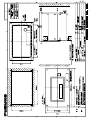
176.+0'&4#9+0)
,2'0
ᄖኸ࿑㧔⧷㧕
࿑ᦠ
176.+0'
+056#..#6+10/#6'4+#.5
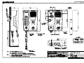
70+6
219'4%#$.'
(14&%/#+05
㔚Ḯ㩃㨺㩖㩨㩣㧰㧯↪
%#$.'#55;
㩃㨺㩖㩨㩣⚵ຠ
Ꮏ᧚ᢱ
24+06'470+6
㩖㩩㩢㩧㩊
࡙࠾࠶࠻
22
㧼㧭㧯㧷㧵㧺㧳ޓ㧸㧵㧿㨀
Y. Hatai
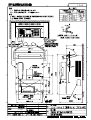
D-1
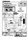
Y. Hatai
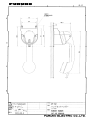
D-2
Y. Hatai
D-3
D-4
Y. Hatai
Y. Hatai
D-5
Y. Hatai
D-6
This page is intentionally left blank.
D-7
Y. Hatai
D-8
Y. Hatai
Mar.11'04
H.Hayashi
D-9
D-10
D-11
Feb.02'05
D-12
D-13
Nov.28'03
D-14
D-15
Y. Hatai
D-16
Y. Hatai
D-17
D-18
Dec.26'03
D-19
Dec.26'03
Y. Hatai
D-20
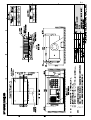
1
2
3
4
*2
*2
A
接続箱
JUNCTION BOX
IF-8810
送受信機
TRANSCEIVER UNIT
FM-8800D/S
T/R用アンテナ
ANTENNA FOR T/R
IEC61162-1(NMEA)/REMOTE
CH70 WR用アンテナ
ANTENNA FOR CH70 WR
+15VDC 1
+15VDC 2
+15VDC 3
+15VDC 4
N.C 5
N.C 6
TXD(H) 7
TXD(C) 8
RXD(H) 9
RXD(C) 10
*2
M-P-5
D-SUB 37P
ANT
1
2
1
2
EXT.ALM_N
0V
W-MIC1(H)
W-MIC1(C)
W-SP1(H)
W-SP1(C)
W-PTT1_N
0V
0V
0V
0V
0V
11
12
13
14
15
16
17
18
19
20
21
22
VDR AF(H)
VDR AF(C)
DATA_A
DATA_B
LINE OUT(H)
LINE OUT(C)
LINE IN(H)
LINE IN(C)
W-MIC2(H)
W-MIC2(C)
W-SP2(H)
W-SP2(C)
W-PTT2_N
0V
F.GND
23
24
25
26
27
28
29
30
31
32
33
34
35
36
37
B
HANDSET
ハンドセット
1
2
3
4
5
6
7
8
HANDSET
HS-2003
外部スピーカ
EXT. SP
S.GND
PTT SW_N
MIC(H)
MIC(C)
HS SP(H)
HOOK SW_N
+5V
F.GND
SPKR
1
2
2.8 m
SP(H)
SP(C)
SEM-21Q *2
C
*1
DPYC-1.5
100-115/
200-230 VAC
AC
IN
*1
DPYC-2.5
+ 24VDC
24 VDC
- IN
AC/DC電源
AC-DC POWER
SUPPLY
PR-240-CE
*2
DC +
OUT -
PE 保護アース
IV-2sq. *1
24VDC
24 VDC
RED
BLK
D
RED
05S9371,3m
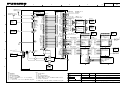
注記 *1)造船所手配。 15A
*2)オプション。
*3)最大4台まで接続可能。
*4)ケーブルクランプで接地。
*5)終端のユニットでは内部で
ジャンパー(J2, J3)をONにする。
*6)P: 撚り対線
*7)ノーマルクローズ、フローティング
最大80mA、耐圧≦50V。
NOTE *1.
*2.
*3.
*4.
*5.
SHIPYARD SUPPLY
OPTION
Max. 4 sets
GROUND THROUGH CABLE CLAMP.
CONNECT JUMPERS (J2 & J3)
ON TERMINATED REMOTE STATION.
*6. P: TWISTED PAIR CABLE
*7. NORMAL CLOSE, FLOATING, MAX80mA,
WITHSTAND VOLTAGE ≦50V.
BLK
24VDC(+)
24VDC(-)
GND
PRINTER
STROBE_N
D0
D1
D2
D3
D4
D5
D6
D7
ACK_N
BUSY
PE
SELECT
ALF_N
ERROR_N
INIT._N
SLCT IN_N
F.GND
0V
F.GND
F.GND
F.GND
F.GND
F.GND
F.GND
P
P
P
P
P
P
P
P
P
P
P
P
P
P
P
P
P
*2
D-SUB 25P
1
2
3
4
5
6
7
8
9
10
11
12
13
14
15
16
17
18
19
20
21
22
23
24
25
TXD(H)
TXD(C)
RXD(H)
RXD(C)
F.GND
EXT.ALM_N
*7
0V
F.GND
W-MIC1(H)
W-MIC1(C)
W-SP1(H)
W-SP1(C)
J2
W-PTT1_N
1
0V
2
F.GND
3
W-MIC2(H)
4
W-MIC2(C)
5
W-SP2(H)
6
W-SP2(C)
7
W-PTT2_N
8
0V
9
F.GND
10
VDR AF(H)
11
VDR AF(C)
12
NOT USED_1
NOT USED_2
J3
F.GND
1
+15VDC
2
0V
3
DATA_A
4
DATA_B
5
LINE IN(H)
6
LINE IN(C)
7
LINE OUT(H)
8
LINE OUT(C)
9
F.GND
10
N.C
11
+15VDC
12
0V
13
DATA_A
14
DATA_B
LINE IN(H)
LINE IN(C)
LINE OUT(H)
LINE OUT(C)
F.GND
N.C
N.C
1
2
3
4
5
6
7
8
9
10
P
CH70 RX ANT
M-P-5
J1
1
2
3
4
5
6
7
8
9
10
11
12
13
14
15
16
17
18
19
20
21
22
23
24
25
26
27
28
29
30
31
32
33
34
35
36
37
38
39
40
41
42
43
44
45
46
47
48
航法装置,プロッタ
NAVIGATION
DEVICE, PLOTTER
RXD(H)
RXD(C)
TXD(H)
TXD(C)
*2
CO-SPEVV-SB-C
*4 0.2X2P,φ10.5
キ
YEL
P ダイ
ORG
アカ
RED
P チャ
BRN
*1
TTYCS-1 MAX. 20m
*4
*4
アカ
Pキ
クロ
Pキ
シロ
Pキ
RED
YEL
BLK
YEL
WHT
YEL
アカ
Pキ
クロ
Pキ
シロ
Pキ
RED
YEL
BLK
YEL
WHT
YEL
17JE-23250-02,3m
プリンタ*2
PRINTER
VDR
*4
*2
05S0309
P
P
P
P
終端まで最大50m
MAX. 50m TO LAST UNIT
シロ(太)
クロ(太)
ミドリ
アオ
キ
ダイ
アカ
チャ
PP-510
*2
*2
Wing Mic
マイクレセプタクルボックス
MIC RECEPTACLE BOX
RBD-VHF(B)
ハンドセット
HANDSET
TB1
1
2
3
4
5
6
7
HS-6000FZ-11
HS-6000FZ-5
外部アラーム
Ext. Alarm *1
1
2
3
4
キ
シロ
アカ
キ
クロ
キ
YEL
WHT
RED
YEL
BLK
YEL
1
2
3
4
5
6
7
8
*4
シロ(太)
P クロ(太)
ミドリ
P アオ
キ
P ダイ
アカ
P チャ
WHT(BIG)
BLK(BIG)
GRN
BLU
YEL
ORG
RED
BRN
+15VDC
1
OV
2
DATA_A
3
DATA_B
4
LINE IN(H) 5
LINE IN(C) 6
LINE OUT(H) 7
LINE OUT(C) 8
TB3
WHT(BIG)
BLK(BIG)
GRN
BLU
RED
BRN
YEL
ORG
TB1
P
P
*4
アカ RED
クロ BLK
シロ WHT
TB1
*4
11
12
13
14
17
18
15
16
F.GND 19
TXD(H)
TXD(C)
RXD(H)
RXD(C)
F.GND
IV-1.25sq.
*1
20
21
22
23
24
1
2
3
4
5
6
7
8
P
P
4
YEL
WHT
RED
YEL
BLK
YEL
P
P
P
ハンドセット
*2
HANDSET
HS-8800
リモートステーション 4
REMOTE STATION *2
RB-8800/RB-8810
DATA_A 1
*3
DATA_B 2
*5
CONT 3
DIST_SW 4
LINE OUT(H) 5
LINE I/O(C) 6
LINE IN(H) 7
+15V1 8
OV 9
F.GND 10
TB1
TB2
左と同じ
Same as
left
TB3
TB3
TB3
IV-1.25sq. *1
リモートステーション
REMOTE STATION *2
RB-8800/RB-8810
*3
*5
1
2
3
4
5
6
7
8
9 F.GND
10 N.C
24VDC
リモートステーション 3
REMOTE STATION *2
RB-8800/RB-8810
DATA_A 1
*3
DATA_B 2
CONT 3
DIST_SW 4
LINE OUT(H) 5
LINE I/O(C) 6
LINE IN(H) 7
+15V1
8
OV 9
F.GND 10
TB1
TB2
IV-1.25sq. *1
DMC I/F *2
IF-8820
キ
シロ
アカ
キ
クロ
キ
1
2
3
ハンドセット
*2
HANDSET
HS-8800
左と同じ
Same as
left
IV-1.25 *1
MAX. 50m TO LAST UNIT
1
2
3
4
5
6
7
CO-SPEVV-SB-C 0.2x5P,φ13.5 MAX.20m *2
1
2
3
4
5
6
7
8
*2
05S0309
終端まで最大50m
マイクレセプタクルボックス
MIC RECEPTACLE BOX
RBD-VHF(B)
HS-6000FZ-11
HS-6000FZ-5
P
リモートステーション 2
REMOTE STATION *2
RB-8800/RB-8810
DATA_A 1
*3
DATA_B 2
CONT 3
DIST_SW 4
LINE OUT(H) 5
LINE I/O(C) 6
LINE IN(H) 7
+15V1 8
OV 9
F.GND 10
TB2
TB1
シロ(太)
Pクロ(太)
ミドリ
Pアオ
アカ
Pチャ
キ
Pダイ
*2
ハンドセット
HANDSET
ハンドセット
*2
HANDSET
HS-8800
リモートステーション 1
REMOTE STATION *2
RB-8800/RB-8810
DATA_A 1
*3
DATA_B 2
CONT 3
DIST_SW 4
LINE OUT(H) 5
LINE I/O(C) 6
LINE IN(H) 7
+15V1 8
OV 9
F.GND 10
TB2
TB1
WHT(BIG)
BLK(BIG)
GRN
BLU
YEL
ORG
RED
BRN
VCTF0.75x3C,5m,φ7
+ 1
- 2
GND 3
*2
Wing Mic
ハンドセット
*2
HANDSET
HS-8800
TTYCS-1 MAX. 20m *1
S-1
6
CO-SPEVV-SB-C 0.2x5P,φ13.5 MAX. 20m *2
IV-1.25sq.
*1
IV-1.25sq. *1
ハンドセット *2
HANDSET 上に同じ
Same as
HS-8800 above
TB2
+15VDC
OV
DATA_A
DATA_B
上に同じ
LINE IN(H)
Same as
LINE IN(C)
above
LINE OUT(H)
LINE OUT(C)
TB3
IV-1.25sq.*1
ダイ
ORG
キ
YEL
チャ
BRN
アカ
RED
*1 CO-SPEVV-SB-C
0.2x2P(5/10/15/20/30m)
遭難警報装置
*2
DISTRESS MESSAGE CONTROLLER
DMC-5
1
2
3
4
6
TB1/TB2
TXD(H)
TXD(C)
RXD(H)
RXD(C)
F.GND
IV-1.25sq.
*1
プリンタ*2
PRINTER
VCTF0.75x2C,3m
+ 1
- 2
シロ WHT
クロ BLK
PP-8800
*1
IV-2sq.
5
IV-1.25sq.
*1
24VDC
DRAWN
Jun. 9,'06
CHECKED
APPROVED
SCALE
DWG No.
E.MIYOSHI
TAKAHASHI.T
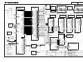
TITLE
FM-8800D/S
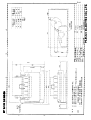
名称
国際VHF無線電話装置
相互結線図
NAME
VHF RADIOTELEPHONE
INTERCONNECTION DIAGRAM
Y. Hatai
MASS
C5642-C01- J
kg
FURUNO ELECTRIC CO., LTD.
3
M-P-5
M-P-5
ハンドセット
HANDSET
HS-2003
B
外部スピーカ
EXT. SPEAKER
SEM-21Q *2
1
2
1
2
1
2
3
4
5
6
7
8
φ3.5
2.8m
ANT
J1
IEC61162-1(NMEA)/REMOTE
CH70 RX ANT
J2
HANDSET
S.GND
PTT SW-N
MIC-H
MIC-C
HS SP-H
HOOK SW-N
+5V
F.GND
SPKR
SP-H
SP-C
GND
C
XM2A-3701
+15VDC 1
+15VDC 2
+15VDC 3
+15VDC 4
NC 5
NC 6
TXD-H 7
TXD-C 8
RXD-H 9
RXD-C 10
*1
非常灯
*2
EMERGENCY LAMP
TB1
1
2
3
4
5
6
7
8
11
12
13
14
15
16
17
18
19
20
21
22
VDR AF-H
VDR AF-C
DATA-A
DATA-B
LINE OUT-H
LINE OUT-C
LINE IN-H
LINE IN-C
W_MIC2-H
W_MIC2-C
W_SP2-H
W_SP2-C
W_PTT2-N
0V
F.GND
23
24
25
26
27
28
29
30
31
32
33
34
35
36
37
1
15A
RED
BLK
2
3
4
5
6
7
8
9
10
11
12
13
14
15
P
P
P
P
P
W_MIC2-H
W_MIC2-C
W_SP2-H
W_SP2-C
W_PTT2-N
0V
F.GND
16
17
18
19
20
21
22
VDR AF-H
VDR AF-C
J3
NOT USED_1
1
NOT USED_2
2
F.GND
3
4
+15VDC
5
0V
6
DATA-A
7
DATA-B
8
LINE IN-H
9
LINE IN-C
10
LINE OUT-H
11
LINE OUT-C
12
F.GND
13
NC
14
23
24
25
26
27
J2
EXT.ALM-N
0V
W_MIC1-H
W_MIC1-C
W_SP1-H
W_SP1-C
W_PTT1-N
0V
0V
0V
0V
0V
PRINTER
24VDC DPYC-2.5
TXD-C
RXD-H
RXD-C
F.GND
EXT.ALM-N
*7
0V
F.GND
W_MIC1-H
W_MIC1-C
W_SP1-H
W_SP1-C
W_PTT1-N
0V
F.GND
J1
1
2
3
4
5
6
7
8
9
10
1
2
3
4
5
6
7
8
9
10
11
12
P
P
P
P
P
P
P
P
P
P
P
P
P
D-SUB 25P
24VDC(+)
24VDC(-)
25
S1
1
2
3
1 ~ 36
J3
0V
24V
J2
+15VDC
0V
DATA-A
DATA-B
LINE IN-H
LINE IN-C
LINE OUT-H
LINE OUT-C
F.GND
NC
NC
28
29
30
31
32
33
34
35
36
37
38
39
40
41
42
43
44
45
46
47
48
TTYCS-4(*1) OR
CO-SPEVV-SB-C
0.2x2P,φ10.5(*2)
航法装置/プロッタ
NAVIGATOR
PLOTTER
P
P
*1
TTYCS-1,MAX.20m
*2
CO-SPEVV-SB-C 0.2x5P,
*4 φ13.5,MAX.20m
アカ RED
P
キ YEL
クロ BLK
P
キ YEL
シロ WHT
P
キ YEL *2
*4 CO-SPEVV-SB-C 0.2x5P,
φ13.5,MAX.20m
アカ RED
キ YEL
クロ BLK
キ YEL
シロ WHT
キ YEL
*4
*1
TTYCS-1,MAX.20m
*4
外部アラーム *1
EXTERNAL ALARM
TB1 マイクレセプタクル
1 ボックス
2 MIC RECEPTACLE
3 BOX
4 RBD-VHF(B) *2
TB1 マイクレセプタクル
1 ボックス
2 MIC RECEPTACLE
3 BOX
4 RBD-VHF(B) *2
VDR
*4
*2
05S0309
終端まで最長50m
TOTAL 50m OR LESS TO TERMINATE
シロ(太)
クロ(太)
ミドリ
アオ
アカ
チャ
キ
ダイ
P
P
P
P
WHT[B]
BLK[B]
GRN
BLU
RED
BRN
YEL
ORG
1
2
3
4
5
6
7
8
*4
*2
05S0309
TOTAL 50m OR LESS TO TERMINATE
シロ(太)
クロ(太)
ミドリ
アオ
アカ
チャ
キ
ダイ
P
P
P
WHT[B]
BLK[B]
GRN
BLU
RED
BRN
YEL
ORG
*4
1 ~ 34
1 ~ 34
1
2
3
4
5
7
HS-6000FZ-11
HS-6000FZ-5
Wing Mic
ハンドセット
HANDSET *2
1
2
3
4
5
7
HS-6000FZ-11
HS-6000FZ-5
TB2
リモートステーション
REMOTE STATION
RB-8800/RB-8810
<No.1>
*3
LINE IN-H
LINE IN-C
LINE OUT-H
LINE OUT-C
1
2
3
4
5
6
7
8
*1
IV-1.25sq.
終端まで最長50m
P
Wing Mic
ハンドセット
HANDSET *2
TB1
1
DMC I/F
2
IF-8820 *2
3
4
5
6
7
8
9 F.GND
F.GND
10 NC
11
12
13
14
15
16
17
18
19
TXD-H
TXD-C
RXD-H
RXD-C
F.GND
20
21
22
23
24
I/F
05P0541
J1
S-2
6
*6
ハンドセット
HANDSET *2
1
2
3
4
5
6
7
8
9
10
A
CH70 WR用アンテナ *2
ANTENNA FOR CH70 WR
接続箱
JUNCTION BOX
IF-8810
TXD-H 1
送受信機
TRANSCEIVER UNIT
FM-8800D/S
5
HS-8800
*2
05S0309
シロ(太)
クロ(太)
ミドリ
アオ
アカ
チャ
キ
ダイ
*2
05S0309
シロ(太)
クロ(太)
ミドリ
アオ
アカ
チャ
キ
ダイ
ハンドセット
HANDSET *2
HS-8800
DATA-A
DATA-B
CONT
DIST_SW
LINE OUT-H
LINE I/O-C
LINE IN-H
+15V1
OV
F.GND
T/R用アンテナ *2
ANTENNA FOR T/R
4
1
2
3
4
5
6
7
8
9
10
2
DATA-A
DATA-B
CONT
DIST_SW
LINE OUT-H
LINE I/O-C
LINE IN-H
+15V1
OV
F.GND
1
TB1
WHT[B]
BLK[B]
GRN
BLU
RED
BRN
YEL
ORG
1
2
3
4
5
6
7
8
TB2
1
リモートステーション 2
REMOTE STATION
RB-8800/RB-8810 3
4
<No.2>
*3
5
6
7
8
*5
リモートステーション
REMOTE STATION
RB-8800/RB-8810
<No.3/No.4>
*1
IV-1.25sq.
1 TB1
2 リモートステーション
3 REMOTE STATION
RB-8800/RB-8810
4
*3
5
6
7
8
WHT[B]
BLK[B]
GRN
BLU
RED
BRN
YEL
ORG
ハンドセット
HANDSET *2
HS-8800
*5
リモートステーション
REMOTE STATION
RB-8800/RB-8810
*1
IV-1.25sq.
*2
CO-0.2x2P,5/10/15/20/30m
P
P
*1
IV-1.25sq.
1
2
3
4
5
TB1/TB2
TXD-H
TXD-C
RXD-H
RXD-C
F.GND
遭難警報装置
DISTRESS MESSAGE
CONTROLLER
DMC-5
*1
IV-1.25sq.
J2
プリンタ
PRINTER
UTP-80FK
D
*6
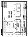
RACK CONSOLE
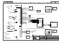
注記
*1)造船所手配。
*2)オプション。
*3)最大4台まで接続可能。
*4)ケーブルクランプで接地。
*5)終端ユニットは内部のジャンパー(J2,J3)をONにする。
*6)プリンタ有の場合
*7)ノーマルクローズ、フローティング、最大80mA、耐圧≦50V。
NOTE
*1.
*2.
*3.
*4.
*5.
*6.
*7.
SHIPYARD SUPPLY
OPTION
MAX. 4 SETS AVAILABLE
GROUND THROUGH CABLE CLAMP.
CONNECT JUMPERS (J2 & J3) ON TERMINATED REMOTE STATION.
IN CASE OF "W/PRINTER"
NORMAL CLOSE, FLOATING, MAX80mA, WITHSTAND VOLTAGE ≦50V.
DRAWN
Jun.9,'06
CHECKED
APPROVED
SCALE
DWG No.
E.MIYOSHI
TAKAHASHI.T
TITLE
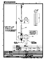
RC-8800 (FM-8800)
名称
国際VHF無線電話装置(ラック組込)
相互結線図
NAME
VHF RADIOTELEPHONE (RACK CONSOLE)
INTERCONNECTION DIAGRAM
Y. Hatai
MASS
C5642-C02- D
kg
FURUNO ELECTRIC CO., LTD.
1
2
T/R用アンテナ
ANTENNA FOR T/R
CH70 WR用アンテナ
ANTENNA FOR CH70 WR
M-P-5
1
2
CH70 RX ANT
M-P-5
1
2
B
HANDSET
ハンドセット
1
2
3
4
5
6
7
8
HANDSET
HS-2003
S.GND
PTT SW_N
MIC(H)
MIC(C)
HS SP(H)
HOOK SW_N
+5V
F.GND
SPKR
1
2
2.8 m
SP(H)
SP(C)
SEM-21Q *2
C
100-115/200-230 VAC
24 VDC
*1
DPYC-1.5
*1
DPYC-2.5
+ 24 VDC
- IN
*2
DC +
OUT -
PE 保護アース
IV-2sq. *1
24 VDC
24 VDC
05S9371,3m
RED
15A
D
BLK
RED
BLK
24 VDC(+)
24 VDC(-)
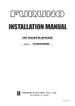
注記
*1)造船所手配。
*2)オプション。
*3)ケーブルクランプで接地。
*4)コネクタクランプで接地。
*5)ノーマルクローズ、フローティング
最大80mA、耐圧≦50V。
NOTE
*1.
*2.
*3.
*4.
*5.
SHIPYARD SUPPLY
OPTION
GROUND THROUGH CABLE CLAMP.
GROUND THROUGH CONNECTOR CLAMP.
NORMAL CLOSE, FLOATING, MAX80mA,
WITHSTAND VOLTAGE ≦50V.
EXT.ALM_N
*5
0V
F.GND
11
12
37
W-MIC1(H)
W-MIC1(C)
W-SP1(H)
W-SP1(C)
W-PTT1_N
0V
F.GND
13
14
15
16
17
18
37
GND
P
P
+15VDC
0V
DATA_A
DATA_B
LINE IN(H)
LINE IN(C)
LINE OUT(H)
LINE OUT(C)
F.GND
1
19
25
26
27
28
29
30
37
W-MIC2(H)
W-MIC2(C)
W-SP2(H)
W-SP2(C)
W-PTT2_N
0V
F.GND
31
32
33
34
35
36
37
STROBE_N
D0
D1
D2
D3
D4
D5
D6
D7
ACK_N
BUSY
PE
SELECT
ALF_N
ERROR_N
INIT._N
SLCT IN_N
F.GND
0V
F.GND
F.GND
F.GND
F.GND
F.GND
F.GND
*2
CO-SPEVV-SB-C 0.2X2P,φ10.5
キ
YEL
ダイ
ORG
アカ
RED
チャ
BRN
*4
P
P
P
アカ
キ
クロ
キ
シロ
キ
*4
*4
P
P
P
P
*4
P
P
P
P: 撚り対線
P: TWISTED PAIR CABLE
P
TB1
YEL
WHT
RED
YEL
BLK
YEL
1
2
3
4
5
6
7
1
2
3
4
HS-6000FZ-11
HS-6000FZ-5
VDR
WHT(BIG)
BLK(BIG)
GRN
BLU
YEL
ORG
RED
BRN
*2
05S0309
終端まで最大50m
DMC I/F *2
IF-8820
MAX. 50m TO LAST UNIT
RED
YEL
BLK
YEL
WHT
YEL
1
2
3
4
5
6
7
8
9 F.GND
10 N.C
*3
11
12
13
14
17
18
15
16
F.GND 19
TXD(H)
TXD(C)
RXD(H)
RXD(C)
F.GND
*4
*2
D-SUB 25P
1
2
3
4
5
6
7
8
9
10
11
12
13
14
15
16
17
18
19
20
21
22
23
24
25
P
キ
シロ
アカ
キ
クロ
キ
ハンドセット
HANDSET
*2
CO-SPEVV-SB-C 0.2x5P,φ13.5 MAX. 20m *2
TTYCS-1 MAX. 20m *1
アカ
キ
クロ
キ
シロ
キ
P
外部アラーム
Ext. Alarm
*1
RED
YEL
BLK
YEL
WHT
YEL
シロ(太)
クロ(太)
ミドリ
アオ
キ
ダイ
アカ
チャ
Wing Mic
マイクレセプタクルボックス
*2
MIC RECEPTACLE BOX
RBD-VHF(B)
*1
TTYCS-1 MAX. 20m
20
21
22
23
24
遭難警報装置
DISTRESS MESSAGE CONTROLLER
DMC-5
P
P
ダイ
ORG
キ
YEL
チャ
BRN
アカ
RED
CO-SPEVV-SB-C
0.2x2P(5/10/15/20/30m),φ10.5
1
2
3
4
6
TB1/TB2
TXD(H)
TXD(C)
RXD(H)
RXD(C)
F.GND
*2
IV-1.25sq.
*1
CO-SPEVV-SB-C 0.2x5P,φ13.5 MAX. 20m *2
17JE-23250-02,3m
プリンタ*2
PRINTER
PP-510
VCTF0.75x3C,5m,φ7
+ 1
- 2
GND 3
アカ RED
クロ BLK
シロ WHT
24VDC
P
P
P
VCTF0.75x2C,3m
プリンタ*2
PRINTER
+ 1
- 2
シロ WHT
クロ BLK
IV-1.25sq.
*1
E. MIYOSHI
TAKAHASHI.T
APPROVED
Y. Hatai
SCALE
MASS
DWG No.
キ
シロ
アカ
キ
クロ
キ
YEL
WHT
RED
YEL
BLK
YEL
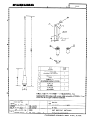
C5642-C03- D
kg
ハンドセット
*2
HANDSET
TB1
1
2
3
4
24VDC
DRAWN
Jun. 9,'06
CHECKED
Wing Mic
マイクレセプタクルボックス
*2
MIC RECEPTACLE BOX
RBD-VHF(B)
IV-1.25sq.
*1
PP-8800
*1
IV-2sq.
S-3
6
航法装置,プロッタ
NAVIGATION
DEVICE, PLOTTER
RXD(H)
RXD(C)
TXD(H)
TXD(C)
*4
VDR AF(H) 23
VDR AF(C) 24
F.GND 37
PRINTER
AC/DC電源
AC-DC POWER
SUPPLY
PR-240-CE
AC
IN
D-SUB 37P
TXD(H) 7
TXD(C) 8
RXD(H) 9
RXD(C) 10
F.GND 37
ANT
5
*2
IEC61162-1(NMEA)/REMOTE
*2
外部スピーカ
EXT. SP
4
送受信機
TRANSCEIVER UNIT
FM-8800D/S
*2
A
3
1
2
3
4
5
6
7
HS-6000FZ-11
HS-6000FZ-5
TITLE
FM-8800D/S
名称
国際VHF無線電話装置
相互結線図(接続箱無し)
NAME
VHF RADIOTELEPHONE
INTERCONNECTION DIAGRAM(W/O J.B.)
FURUNO ELECTRIC CO., LTD.