1
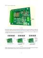
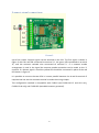
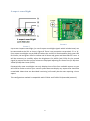
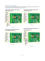
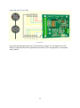
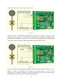
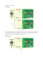
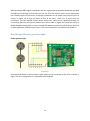
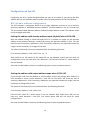
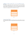
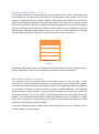
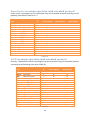
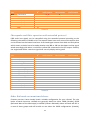
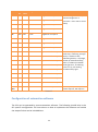
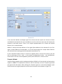
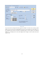
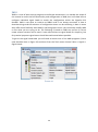
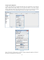
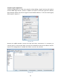
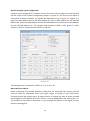
Signalist SC1
DCC signal controller user manual
Covers configuration for North American
signals
1
Contents
Contents......................................................................................................................................................2
Signalist SC1 user manual ...............................................................................................................................4
Overview .....................................................................................................................................................4
Connections and configuration ...................................................................................................................4
DCC track connection..............................................................................................................................5
2-aspect signal connections ....................................................................................................................6
3 or 4-aspect with individual lamps ........................................................................................................7
2/3-aspect searchlight ............................................................................................................................8
4-aspect searchlight ................................................................................................................................9
Multi-head searchlight ..........................................................................................................................10
Amtrak position light ............................................................................................................................12
Pennsylvania Rail Road Position light ...................................................................................................13
Baltimore and Ohio ...............................................................................................................................14
Norfolk and Western position light ......................................................................................................15
Configuration of the SC1 ...........................................................................................................................16
DCC decoder address configuration .....................................................................................................16
Setting the signal type ..........................................................................................................................18
Setting the signal polarity .....................................................................................................................20
Setting the default state .......................................................................................................................20
Setting the brightness of individual LEDs..............................................................................................20
Special effects .......................................................................................................................................20
Operation ..................................................................................................................................................22
General..................................................................................................................................................22
2-aspect.................................................................................................................................................22
3-aspect or 4-aspect (except CV38 = 7, 8, 11or extended accessory protocol) ....................................23
3-aspect when CV38=8 .........................................................................................................................23
3-aspect when CV38 = 7 or 11 ..............................................................................................................24
Extended accessory protocol ................................................................................................................24
Extended accessory protocol when CV38 = 128 – 134 and 65-95 ........................................................25
User defined aspects when CV38 = 135................................................................................................25
Canada multi-head operation with extended protocol ........................................................................26
Amtrak position light operation with extended protocol .....................................................................27
Baltimore and Ohio position light operation with extended protocol .................................................28
Norfolk and Western using extended protocol ....................................................................................28
2
Pennsylvania Railroad position light operation with extended protocol .............................................29
Union Pacific Searchlight operation with extended protocol ...............................................................30
ATSF Searchlight operation with extended protocol ............................................................................30
Seaboard System Searchlight operation with extended protocol ........................................................31
NORAC generic Searchlight operation with extended protocol ...........................................................31
Chesapeake and Ohio operation with extended protocol....................................................................32
Other Railroads not mentioned above .................................................................................................32
List of Configuration Variables ..................................................................................................................34
Configuration of automation software .....................................................................................................35
Railroad & Co ........................................................................................................................................36
JMRI ......................................................................................................................................................40
RocRail ..................................................................................................................................................46
Specification..............................................................................................................................................54
3
Signalist SC1 user manual
Overview
The signalist SC1 is a highly versatile DCC accessory decoder optimised for driving LED based
signals and will drive any LED based signal that will operate from a 5V supply. The SC1 does
not require any external power supply and is simply powered from the DCC track supply.
The SC1 can typically drive up to eight signal lamps or lamp groups in various configurations
allowing the connection of most of the signal types found in North America (very complex
installations with more than eight lamp groups may need more than one SC1). The flexible
output configuration can drive searchlight signals using multicolour LEDs and position light
signals. Configurations have been included to cover the complex speed signalling systems
with the simple application of rules. Configuration of signal type and address is by standard
programming of configuration variables on the DCC programming track connection from a
command station or dedicated DCC programmer such as a Sprog. The address can be
changed without requiring connection to the programming track.
My thanks go to the excellent Railroad Signals of the US website which is an excellent
reference for the myriad of different signalling systems in use in both the USA and Canada.
Connections and configuration
The following section shows how to connect the SC1 to the signals and DCC system and
covers basic configuration for each type of signalling. The diagrams all show common
cathode wiring but if common anode signals are used the common wire should be
connected to terminal ‘a’ instead of terminal ‘k’ and output reversal with CV37 should be
done to suit.
Single head installations are straightforward to connect but multi-head signals need to be
connected in a specific way depending on type if the Signalist SC1 is to convert the railroad
rules in to aspect displays. You will need to connect the heads as individual signals if you are
using turnout addresses for your signals rather than extended accessory signal addresses.
4
DCC track connection
FIGURE 1
Only the DCC signal is required to control and power the SC1 via terminal block J2 which will
normally be connected to the accessory bus for maximum reliability, but if you do not have
a separate accessory bus it can be connected to the track bus or just to the track adjacent to
the signal. The various options are shown in Figure 2.
FIGURE 2
When programming the SC1, J2 will need to be connected to the programming track output
of the command station instead of the normal track output connection.
5
2-aspect signal connections
FIGURE 3
Up to four simple 2-aspect signals can be attached to the SC1. The first signal is shown in
Figure 3 with the red LED connected to terminal ‘A’, the green LED connected to terminal
‘B’, and the common cathode wire connected to terminal ‘k’. If a common anode
arrangement is used in the signal the common anode connection can be made to the ‘a’
terminal. If a distant signal is used the yellow LED should be connected in place of the red
LED shown in Figure 3.
It is possible to connect the two LEDs in inverse parallel between the A and B terminals if
required and not use the common terminal to make the wiring simpler.
This configuration method is compatible with CV38=0 (and CV38=14 E+F and G+H only,
CV38=6 G+H only) and CV38=129 (extended accessory protocol).
6
3 or 4-aspect with individual lamps
FIGURE 4
Two 3-aspect or 4-aspect signals can be connected to the SC1 as shown in Figure 4. If 3aspect signals are used just omit the connection to the unused aspect and the signal will be
dark instead. Use this configuration if creating a signal mast from individual heads rather
than using a specific multi-head configuration.
This configuration method is fully compatible with CV38=64 or CV38=67 (extended
accessory protocol).
7
2/3-aspect searchlight
FIGURE 5
Up to four 2-aspect searchlight signals or 3-aspect searchlight signals can be connected to
the SC1 as shown in Figure 5. 2-aspect searchlight signals may or may not have a common
connection as shown in Figure 6, and if not there is no need to make a common connection.
3-aspect signals must have common anode or cathode.
FIGURE 6
The yellow aspect is achieved by turning on both the red and green LEDs at once. Careful
adjustment of the brightness CVs will enable the best yellow colour to be displayed. It is not
possible to display Lunar as one of the aspects using this method.
This configuration can be used to connect the individual heads of a multihead searchlight
mast if a specific multihead configuration is not being used.
This configuration method is compatible with CV38=0 (2-aspect only), CV38=8 (3-aspect) or
CV38=129 (3-aspect extended protocol).
8
4-aspect searchlight
F IGURE 8
FIGURE 7
Up to two 4-aspect searchlight, (or two 3-aspect searchlight signals which include Lunar) can
be connected to the SC1 as show in Figure 8 There is no connection to terminals ‘D’ or ‘H’.
Four aspect searchlights use an RGB LED where the red LED is illuminated for Red, green LED
for Green, red and green LEDs for Yellow and all three red, green and blue LEDs for Lunar. It
will be necessary to carefully adjust the brightness CVs 48-50 (and 52-54 for the second
signal) to ensure that the correct colours are displayed adjusting for Green first (CV 49) then
Yellow (CV48) then Lunar (CV50).
Prototypically most searchlights can only display three of the four available aspects so you
will need to make sure that your control system does not display any aspect that should be
unavailable. Masts that are described ‘restricting’ will usually be the ones requiring a lunar
aspect.
This configuration method is compatible with CV38=4 and CV38=132 (extended protocol).
9
Multi-head searchlight
There are several different ways that multi-head searchlight signals can be connected to the
SC1 depending on which aspect patterns are required.
Triple head searchlight without Lunar
(Multihead type ‘A’)
Triple head searchlight with top Lunar
(Multihead type ‘B’)
F IGURE 10
FIGURE 9
Double head searchlight without Lunar
(Multihead type ‘D’)
Triple head searchlight with bottom
Lunar (Multihead type ‘C’)
FIGURE 11
F IGURE 12
10
Double head searchlight with bottom
Lunar (Multihead type ‘F’)
Double head searchlight with 2x Lunar
(Multihead type ‘E’)
F IGURE 14
FIGURE 13
Multihead type ‘A’ shown in figure 9 is compatible with CV38=65 (Canada) and CV38=69
(Norfolk and Western).
Multihead type ‘B’ shown in figure 10 is compatible with CV38=76 (Union Pacific).
Multihead type ‘C’ shown in figure 11 is compatible with CV38=79 (Seaboard) and CV38=81
(NORAC).
Multihead type ‘D’ shown in figure 12 is compatible with CV38=66 (Canada) and CV38=71
(Norfolk and Western).
Multihead type ‘E’ shown in figure 13 is compatible with CV38=70 (Norfolk and Western),
CV38=77 (Union Pacific) and CV38=78 (Atchison, Topeka and Santa Fe).
Multihead type ‘F’ shown in figure 14 is compatible with CV38=80 (Seaboard) and CV38=82
(NORAC).
11
Amtrak position light
FIGURE 15
An Amtrak position light signal can be connected as in Figure 15. The brightness of the
different coloured LEDs can be adjusted with CVs 48-55. This configuration is compatible
with CV38=75.
12
Pennsylvania Rail Road Position light
FIGURE 16
You can connect a PRR position light signal to the SC1 as shown in Figure 16. The
permanently lit centre lamp ‘J’ is powered by a resistor with a value between 220R and 2K2
depending on how bright it needs to be – the other lamps’ brightness can be adjusted by
CVs 48-55 to match. A value of 470R will probably be a good place to start.
FIGURE 17
You can connect the more modern modified ‘Devil eyes’ version with red lamp ‘A’s as in
Figure 17. There is no need for the resistor for the central lamp ‘J’ since it is not
permanently lit, instead six diodes are used to generate the feed for the centre lamp.
Configuration for both versions is compatible with CV38=74
13
Baltimore and Ohio
Full method
FIGURE 18
For a complete B&O position light signal one and a half SC1s are required to operate all ten
lamp groups wired as shown in Figure 18. The first SC1 driving lamp groups A-F uses
CV38=72, the second SC1 driving lamps G-K uses CV38=73
Partial method
FIGURE 19
14
Most prototype B&O signal installations do not require that all possible speeds be signalled
through an interlocking and therefore do not use all of the marker lamps, and in most cases
the unused lamps are not fitted. A reduced installation can be made using only one SC1 as
shown in Figure 19 as long as either of one of the pairs J and K or G and H are not
connected. The full method shown above allows any speed to be signalled through an
interlocking but with the partial method you will be able to signal line speed but have to
decide between being able to signal Limited and Medium speed with white lamps G and H
or Slow speed with yellow lamps J and K. This partial method is compatible with CV38=72.
Norfolk and Western position light
Colour position light
FIGURE 20
A Norfolk and Western colour position light signal can be connected to the SC1 as shown in
Figure 20. This configuration is compatible with CV38=68.
15
Configuration of the SC1
Configuring the SC1 is quite straightforward and may be as simple as just setting the DCC
address but you will probably want to make a few more adjustments for full functionality.
DCC decoder address configuration
The SC1 occupies a contiguous block of up to eight addresses and can be set to use any
accessory address or extended accessory address. The base address is set in CV1 and CV9.
The SC1 supports both decoder address mode and output address mode. The address mode
can be changed with CV29.
Setting the address with decoder address mode (default) when CV29=128
With the default setting of CV29=128 and CV9=0 it is possible to simply set the decoder
address to any address between 1 and 63 by writing the decoder address to CV1. This will
allow the use of accessory addresses 1-252. If accessory addresses are required outside this
range it will be necessary to change CV9 as well.
The values of CV1 and CV9 can be calculated from the following formula:First accessory address = CV9 x 256 + CV1 x 4 – 3
With CV29 set to 128 values of CV1 above 63 are not allowed, and 63 will not work for
configurations that use more than four addresses. CV9 can have values 0-7, values above 7
are not allowed.
See note overleaf about variations in addressing used in some command stations.
Setting the address with output address mode when CV29=192
If you change CV29 from the default to 192 the effect of CV1 will change. With CV9=0 it is
now possible to write a value between 1 and 255 to CV1 which will allow the use of
accessory addresses 1-258. If accessory addresses are required outside this range it will be
necessary to change CV9 as well.
The values of CV1 and CV9 can be calculated from the following formula:First accessory address = CV9 x 256 + CV1
CV9 can have values 0-7, values above 7 are not allowed. With CV29 set to 192 CV1 can
have any value between 1 and 255, but values above 248 will not work for some
configurations.
See note overleaf about variations in addressing used in some command stations.
16
Setting the address automatically
It is possible to set the decoder address automatically using the PGM jumper (shown in
Figure 21). To set the address automatically use the following steps.
1.
2.
3.
4.
Power off the SC1.
Fit the PGM jumper to pins 1 and 2 of J5.
Power on the SC1.
Operate the desired base address on your command station to both Normal and
reverse.
5. Power off the SC1.
6. Remove the PGM jumper.
7. Power on the SC1
The address will now be set in CV1 and CV9 in output address mode with CV29 set to 192.
The decoder will respond to up to eight contiguous addresses starting with the one that was
operated. The jumper must be removed for normal operation.
Normal operation
Jumper fitted for programming
Figure 21 - PGM jumper J5 location
Important note: -
Many command stations and some software
applications do not follow the NMRA accessory numbering scheme, so it is important to be
aware that setting the address CVs according to the NMRA formulae used above may not
work and some addresses may not be accessible. Lenz, ESU and ZTC are notable in this
respect and you will need to make allowance. Some systems can only operate a subset of
the accessory range, often limited to addresses below 256 or below 1024 so this may need
to be taken in to account also before choosing addresses. If you are not sure how the
addressing works on your system use the automatic address setting mode with the PGM
jumper.
17
Setting the signal type
The SC1 needs to be configured to match the signal type that is connected to the J1
terminals and the protocol used by adjustment of CV38. By default CV38 is set to zero which
allows the connection of up to four 2-aspect signals using standard accessory (turnout)
addresses. Table 1 shows the different settings allowed in CV38.
CV38
0
1
2
3
4
5
6
7
8
9
10
11
12
13
14
15
64
65
66
67
68
69
70
71
72
73
Signal type
4x 2-aspect
2x 3-aspect or 4-aspect (UK)
2x 2-aspect with a feather (UK)
1x 3-aspect or 4-aspect (UK) with 3x feathers
2x 3-aspect searchlight or 4-aspect searchlight
1x 3-aspect or 4-aspect searchlight with 3x feathers
1x 3-aspect or 4-aspect(UK) (A-D) with feather (E, F) + 1x 2-aspect (G, H)
2x 4-aspect (UK) allowing dark and flashing aspects
8x individually controlled outputs (4x 3-aspect searchlight)
2x 3-aspect with a feather (UK)
2x 4-aspect searchlight with a feather (UK)
2x 3-aspect or 4-aspect (UK) allowing easy manual control
4x pairs on together (for level crossing etc.)
2x triplets on together (for SPAD indicator etc.) (A-C and D-F)+ pair (G and H)
3-aspect or 4-aspect (UK) (A-D) + 2x 2-aspect (E-F and G-H)
Eight Dapol semaphore signals (requires adaptor board)
2x 4-aspect R/G/Y/L with individual lamps
Canada CROR 3-head searchlight + 1-head searchlight using extended protocol
Canada CROR 2x 2-head searchlight using extended protocol
2x 4-aspect R/G/Y/L with individual lamps using extended protocol
N&W 2-disc colour position light using extended protocol
N&W 3-head searchlight + 1-head searchlight using extended protocol
N&W 2-head searchlight + 1-head searchlight using extended protocol
N&W 2x 2-head searchlight (no lunar aspects) using extended protocol
B&O Disc and markers using extended protocol
B&O 2x supplementary markers using extended protocol
18
CV38
74
75
76
77
78
128
129
130
131
132
133
134
135
Signal type
PRR Disc and Star position light using extended protocol
Amtrak double disc colour position light using extended protocol
UP 3-head searchlight using extended protocol
UP 2-head searchlight + 1-head searchlight using extended protocol
ATSF 2-head searchlight + 1-head searchlight using extended protocol
2x 4-aspect (UK) using extended accessory protocol
4x 3-aspect searchlight using extended accessory protocol
2x 3-aspect with feather (UK) using extended accessory protocol
2x 4-aspect searchlight with a feather (UK) using extended accessory protocol
2x 4-aspect searchlight using extended accessory protocol
1x 3-aspect or 4-aspect (UK) with 3x feathers using extended accessory
protocol
1x
4-aspect searchlight with 3x feathers using extended accessory protocol
Single signal with user defined aspects using extended accessory protocol
TABLE 1
19
Setting the signal polarity
By default the SC1 is configured to work with signals that are wired for common cathode. If
common anode signals are used it will usually be necessary to invert the outputs by setting
CV35=255. Each output is separately configurable by a single bit in CV35 so it is possible to
use a mixture of common anode and common cathode if required.
Setting the default state
By default the signals will be dark (no aspect showing) when the decoder is reset. It is
possible to configure which aspect is shown at reset by changing the value of CV37. Typically
it will be desirable for signals to show clear (automatic block signals) or stop (controlled
signals) when the SC1 is reset until it receives commands to set the aspects. Each bit of CV37
maps to an output, bit 0 = output ‘H’, bit 1 = output ‘G’ etc. so by setting each bit you can
set the relevant LED to be on. Typical values that might be used are CV37 = 136 for a pair of
4-aspect signals to start up on red, or CV37 = 85 for four 2-aspect signals to start up green.
Setting the brightness of individual LEDs
Each output can have its brightness adjusted independently. The default setting of
maximum brightness can result in up to 25mA LED current which in many cases will result in
the LED being much brighter than is prototypically correct. Different coloured LEDs will
behave differently so may appear to be brighter than other similar LEDs of a different
colour.
It is possible to simulate a LED series resistor in the range of 120 Ohms (the default) to
around 2K Ohms by adjusting the value of the brightness CVs 48-55. CV48 allows the
adjustment of the brightness of output ‘A’, CV49 output ‘B’ etc. If it is found that values
lower than 16 are required it may be beneficial to add a 2.2K Ohms or larger series resistor
to the output to prevent the visible flicker which can occur when very low values are being
used in these CVs.
Careful adjustment of the red and green (and blue) brightness values can help to adjust the
shade of yellow (and lunar) present on searchlight signals. On signals where some lamps are
grouped on a single output the outputs with single lamps will need to be dimmed to match.
Special effects
While not relevant to signals specifically it is possible to make use of spare outputs on the
SC1 for animating the lights on static scenic items. The rotating beacon or flashing strobe
effects can be very effective on parked emergency or breakdown vehicles, and the gently
flickering oil lamp effect can be handy to illuminate the spectacle plate of semaphore signals
more realistically or perhaps some workman’s road lamps.
Any unused outputs can be configured to turn on at reset with CV37, and the special effect
can be configured with CVs 56-63. CV56 is for output ‘A’, CV 57 is for output ‘B’ etc. See
Table 2 for the effect assigned to each configuration value. CV38=8 can be useful to control
eight individual LED accessories with the SC1.
20
Value in CV56-63
Effect
0
Always on (default)
1
MARS light
2
Flickering oil lamp
3
Flashing light
4
Single flash xenon strobe
5
Double flash xenon strobe
6
Rotating beacon (‘Fuzz’ light)
7
Gyralight
8
Fade up and down flashing phase 1
9
Fade up and down flashing phase 2
12
Flashing light (alternate to 3)
14
Flashing portable battery warning light
TABLE 2
21
Operation
General
When any aspect is changed on the SC1 the new state is stored in non-volatile memory so
that it can be recovered in the event of a power failure and the aspects will be displayed
when power is restored as if nothing has happened.
When the SC1 is reset by a DCC reset packet it will load up the default aspect settings stored
in CV37. A decoder reset packet is typically sent by the command station following
operation of the emergency stop button and when powering up the command station.
2-aspect
Each 2-aspect signal occupies a single accessory (turnout) address. Operation is by simply
toggling the accessory between normal or straight (clear) and reversed or thrown (Red or
Yellow for a distant signal).
Operation can be by manual control from a hand controller or automatic from the command
station (perhaps using layout automation software or route setting).
State
Home
Distant
Normal
Red
Yellow
Reverse
Green
Green
TABLE 3
If used with JMRI the signal head type is Single Output.
22
3-aspect or 4-aspect (except CV38 = 7, 8, 11or extended accessory
protocol)
Each 3-aspect or 4-aspect signal occupies two consecutive accessory (turnout) addresses.
The lower address toggles between red or green and yellow or lunar while the higher
address toggles red or yellow and green or lunar. On 3-aspect signals the lunar aspect will
display as yellow or dark depending on the signal type. The second signal will use base+2
and base+3 or for configurations with a feather base+3 and base+4.
Base
Base+1
Aspect
state
state
Normal
Normal
Red
Reverse
Normal
Green
Normal
Reverse
Yellow
Reverse
Reverse
Lunar
TABLE 4
3-aspect when CV38=8
Each 3-aspect signal occupies two consecutive accessory (turnout) addresses. The lower
address operates the red LED and the higher address operates the green LED according to
Table 5.
Base
Base+1
state
state
Normal
Normal
Dark
Reverse
Normal
Red
Normal
Reverse
Green
Reverse
Reverse
Yellow
TABLE 5
23
Feather
3-aspect when CV38 = 7 or 11
This setting is available in order to allow for the extra flashing red, yellow, or green aspect to
be displayed and to make manual operation of 3-aspect signals much simpler. Each of the
aspects is assigned to its own accessory address and reversing that address will cause that
aspect to be displayed regardless of the previous aspect. This makes for very quick manual
operation compared to the other methods. Setting the addresses to normal will extinguish
the signal making it dark. Automation software such as JMRI uses this method to create the
flashing aspects by alternating between dark and on. There is no truth table for this method
since the aspect displayed is simply the last one selected as shown in Table 6.
State
Aspect
Normal (all)
Dark*
Reverse base
Red
Reverse base+1
Green
Reverse base+2
Yellow
*NOTE CV38=7 only
TABLE 6
If used with JMRI signal type is triple Output where Green output is base+1, Yellow output is
base+2, Red output is base. The second signal uses base+4, base+5 and base+6.
Extended accessory protocol
The extended accessory protocol allows multi-aspect signals to be set using a single
command on command stations that support it (Sprog, Digitrax, NCE and EasyDCC support
the extended accessory protocol). Each signal occupies just a single signal address regardless
of its number of aspects or heads instead of a group of turnout addresses. The extended
protocol allows a larger number of signals to be controlled and reduces the number of
commands required to set the aspects while flashing aspects are managed within the
decoder. The reduced data overhead and freeing of addresses can be a real boon on a large
layout where response to commands will be significantly improved with upwards of 90%
reduction in signal control packets possible.
To use the Extended protocol in JMRI use the ‘DCC Signal Decoder’ driver. In Rocrail use the
‘Aspect numbers’ control method.
24
Extended accessory protocol when CV38 = 128 – 134 and 65-95
These settings are available in order to allow the use of extended accessory protocol. For
most configurations aspect numbers are Red (0), Green (2), Yellow (1), Lunar (3), Flashing
Red (4), Flashing Green (6), Flashing Yellow (5), Flashing Lunar (7) and Dark (8). For rules
based and multi-head installations the aspect numbers are detailed in the specific section.
Unused aspect values will show as dark.
User defined aspects when CV38 = 135
You can create your own multi-aspect signal definition with up to eight steady lamps and up
to 32 aspects when CV38=135. The aspects are stored consecutively in CV 192-223 where
CV192 is aspect 0, CV193 aspect 1 etc. The eight bits of each aspect CV correspond with the
eight outputs where bit 0 is output H, bit 1 is output G etc. This can be useful for creating
unusual signals like a 7-segment theatre display for instance or an unusual multi-head
installation.
25
Canada multi-head operation with extended protocol
Simple installations might only need single head searchlights as described in the previous
sections, but most of the rules require double or triple head indications. To simplify
operation it is possible to group multi-head installations on the SC1 and operate them as a
group using the extended accessory protocol according to the following table. If your
command station does not support extended accessory protocol you will have to treat all
the heads individually and use software logic to implement the rules.
CROR
Rule
429
430
427
428
426
425
424
423
422
421
420
419
418
417
416
415
414
413
412
411
410
409
408
408A
407
407A
406
406A
405
-
Description
Stop
Take siding
Special protection
Stop and proceed
Restricting
Slow approach
Slow
Slow to Medium
Slow to Limited
Slow to Clear
Medium approach
Medium to Slow
Medium
Medium to Limited
Medium to Clear
Limited approach
Limited to Slow
Limited to Medium
Limited to Limited
Limited to Clear
Approach
Advance Approach
Clear to Slow
Advance Clear to Slow
Clear to Medium
Adv. Clear to Medium
Clear to limited
Advance Clear to limited
Clear
Dark
Aspect
No
0
1
2
3
4
6
7
8
9
10
11
12
13
14
15
16
17
18
19
20
21
22
23
24
25
26
27
28
29
31
Triple (A-F)
CV38=65
RRR
_
_
RRY
RRy
Ryy
RyG
Ryg
RRG
RYR
RG y
RGG
RGg
RGR
RyR
Rg y
RgG
Rgg
RgR
YRR
yRR
YYR
RGy
YGR
GRG
YgR
GRg
GRR
---
Double
CV38=66
RR
_
RR
RR
RY
Ry
RG
YR
yR
YY
Yy
YG
Yg
GR
--
Single (G+H)
CV38=65
R
r
R
R
R
Y
y
G
-
Aspect
No
0
4
0
0
0
8
8
8
8
8
8
8
8
8
8
8
8
8
8
8
1
5
8
8
8
8
8
8
2
8
Key R=Red, r=Flashing Red, G =Green, g=Flashing Green, Y=Yellow, y=Flashing Yellow.
TABLE 7
26
Single
CV38=129
R
r
R
R
R
Y
y
G
-
Amtrak position light operation with extended protocol
Amtrak position lights can be controlled using the extended protocol according to the
following rules when CV38=75. It is possible to have two single head signals using just the
top head when CV38=67.
Amtrak
Rule
292
291
290
288
286
285
284
283
282A
282
281C
281B
281A
281
-
Description
CV38=75
Aspect No
0
1
2
3
4
5
6
7
8
9
10
11
12
13
14
15
Stop
Not used (Dark)
Stop and proceed
Restricting
Slow approach
Medium approach
Approach
Approach Slow
Medium to Clear
Advance Approach
Approach Medium
Limited to Clear
Approach Limited
Cab speed
Clear
Dark
CV38=67
Aspect No
0
1
5
6
2
8
Aspect
R
R
RL
RY
Ry
Y
YY
RG
y
YG
Rg
Yg
g
G
Key R=Red, G =Green, g=Flashing Green, Y=Yellow, y=Flashing Yellow, L=Lunar,
=White.
TABLE 8
It is possible to operate the Amtrak signals without extended protocol when CV38=64 but
the heads will have to be controlled separately in the control system logic.
27
Baltimore and Ohio position light operation with extended protocol
CV38=72 or 73 Aspect No
B&O Rule
Description
292
290
288
287A
287
286
285
284
283B
283A
283
282
281C
281B
281
-
Stop
Restricting
Slow approach
Slow approach slow
Slow clear
Medium approach
Approach
Approach Slow
Medium approach slow
Medium approach medium
Medium to Clear
Approach Medium
Limited to Clear
Approach Limited
Clear
Dark
TABLE 9
0
1
2
3
4
5
6
7
8
9
10
11
12
13
14
15
B&O position lights with markers can be controlled using the extended protocol as shown in
the table above. If it is not possible to use the extended protocol it will be possible to
operate the main head and marker lights in turnout mode using CV38=8 using logic in the
control system to control the lamps individually.
Norfolk and Western using extended protocol
N&W
Rule
292
290
288
287
286
285A
285
283
283B
282A
282
281
-
Description
Stop
Restricting
Slow approach
Slow to Clear
Div approach
Approach distant
Approach
Diverging Clear
Div. Appr. Div.
Advance Approach
Approach Div.
Clear
Dark
Aspect
0
2
4
5
6
7
8
9
10
12
13
14
15
Triple (A-F)
CV38=69
RRR
RRY
RRG
RYR
YRR
RGR
RyR
YYR
YGR
GRR
-
28
Double
CV38=70
RR
RY
YR
G
LY
YR
LG
Ly
YY
YG
GR
-
Double
CV38=71
RR
RY
YR
G
YR
RG
YY
YG
-
Single (G+H)
CV38=69/70
R
R
Y
Y
Y
G
-
N&W
Rule
292
290
288
287
286
285A
285
283
283B
282A
282
281
-
Description
Aspect
Stop
Restricting
Slow approach
Slow to Clear
Div approach
Approach distant
Approach
Diverging Clear
Div. Appr. Div.
Advance Approach
Approach Div.
Clear
Dark
0
2
4
5
6
7
8
9
10
12
13
14
15
Position
CV38=68
RR
R\
YR
R/
Y
Y
LG
R|
Y/
Y|
G
-
Aspect
0
0
1
8
8
1
1
8
8
8
8
2
8
Single
CV38=129
R
R
Y
Y
Y
G
-
Key R=Red, G =Green, Y=Yellow, y=Flashing Yellow, L=Lunar.
TABLE 10
Norfolk and Western have a variety of signalling systems which can be controlled using the
extended protocol as shown above in table 10. CV38=70 displays aspects which include
Lunar while CV38=71 displays the non-Lunar alternative aspects. No signal can display all of
the rules, and some rules are only valid on particular types of mast.
Pennsylvania Railroad position light operation with extended
protocol
PRR position lights can be controlled using the extended protocol according to the following
rules when CV38=74.
PRR
Rule
292
294
291
290
289
288
287
285A
285
284
283A
283
282
281
280
-
Description
Stop
Take siding
Stop and Proceed
Restricting
Permissive
Slow Approach
Slow Clear
Caution
Approach
Approach Slow
Medium App. (flashing)
Medium to Clear
Approach Medium
Clear
Clear Block
Dark
TABLE 11
29
CV38=74
Aspect No
0
1
2
3
4
5
6
7
8
9
10
11
12
13
14
15
Aspect
R
X
RY
R\
\
R/
\Y
/
//
R/
R|
/|
|
|Y
Union Pacific Searchlight operation with extended protocol
Union Pacific searchlights can be controlled using the extended protocol according to the
following rules when CV38=76 or 77.
UP
Rule
245P/Q
245N
245M
245M
245L
245K
245J
245H
245G
245F
245E
245D
245C
245B
245A
-
Description
Stop
Stop and Proceed
Restricting (alt 1)
Restricting (alt 2)
Diverging App. Slow
Diverging Approach
Diverging App. Limited
Diverging Clear Slow
Diverging Clear
Diverging Clear Limited
Div. App. Div.
Approach
Approach Medium
Approach Limited
Clear
Dark
Aspect
No
0
1
2
3
4
5
6
7
8
9
10
11
12
13
14
15
Triple head
when CV38=76
RRR
r-LRR
RLR
RRY
RYR
RyR
RRG
RGR
RgR
YLR
YRR
YYR
YRR
GRR
Double head
when CV38=77
RR
rLR
RL
-RY
Ry
-RG
Rg
YL
YR
YY
YR
GR
Single head
when CV38=77
R
r
R
R
Y
y
G
TABLE 12
ATSF Searchlight operation with extended protocol
Atchison, Topeka and Santa Fe searchlights can be controlled using the extended protocol
according to the following rules when CV38=78.
ATSF
Rule
241/2
241/2
240
240
238
238
237
236
236
235
234
234
232
231
230
230
-
Description
Stop (alt 1)
Stop (alt 2)
Restricting (alt 1)
Restricting (alt 2)
Diverging App. (alt 1)
Diverging App. (alt 2)
Diverging Clear
Approach (alt1)
Approach (alt2)
Approach Restricting
Approach Med. (alt 1)
Approach
Med. (alt 2)
MMed.((alt1)dium
Advance Approach
Approach Limited
Clear (alt 1)
Clear (alt 2)
Dark
Aspect
Double head
o
N
when CV38=78
0
RR
1
R2
RL
3
Rr
4
Ry
5
RY
6
RG
7
YR
8
Y9
YL
10
YY
11
yR
12
yG
13
yg
14
GR
15
G16
TABLE 13
30
Single head
when CV38=78
R
R
R
r
Y
Y
y
y
G
G
Seaboard System Searchlight operation with extended protocol
Seaboard searchlights can be controlled using the extended protocol according to the
following rules when CV38=79 or 80.
Seaboard
Rule
291-5
290
288
287
286
285
284
283B
283A
283
282A
282
286
281C
281B
281
-
Description
Stop
Restricting
Slow Approach
Slow Clear
Medium Approach
Approach
Approach Slow
Medium App. Slow
Medium App. Approach
Medium Clear
Advance Approach
Approach Medium
Limited Approach
Limited Clear
Approach Limited
Clear
Dark
Aspect
No
0
1
2
3
4
5
6
7
8
9
10
11
12
13
14
15
16
Triple head
when CV38=79
RRR
RRL
RRy
RRG
RYR
YRR
YRG
RYG
RYY
RGR
YYR
YGR
RyR
RgR
YgR
GRR
Double head
when CV38=80
RR
RL
--RY
YR
---RG
YY
YG
Ry
Rg
Yg
GR
Single head
when CV38=80
R
L
Y
y
G
TABLE 14
NORAC generic Searchlight operation with extended protocol
Generic Northeastern area searchlights can be controlled using the extended protocol
according to the following rules when CV38=76 or 77. The aspects shown here cover most of
the aspects that can be shown by NORAC member railroads on searchlight heads. Some
aspects have alternate versions so that you can choose the correct version for your locality.
NORAC
Rule
291/2
291/2
290
290
288
287
286
285
285
284
284
283A
283
282A
282
Description
Stop (alt 1)
Stop (alt 1)
Restricting (alt 1)
Restricting (alt 2)
Slow Approach
Slow Clear
Medium Approach
Approach (alt 1)
Approach (alt 2)
Approach Slow (alt 1)
Approach Slow (alt 2)
Medium App. Medium
Medium Clear
Advance Approach
Approach Medium
Aspect
No
0
1
2
3
4
5
6
7
8
9
10
11
12
13
14
Triple head
when CV38=81
RRR
RRR
RRL
RRY
RRy
RRG
RYR
YRR
YRR
YRG
YYR
RYG
RGR
yRR
YGR
31
Double head
when CV38=82
RR
RRL
RY
--Ry
YR
YYY
YY
-RG
yR
YG
Single head
when CV38=82
R
R
L
L
Y
Y
y
-
NORAC
Rule
281C
281B
281A
281
281
281
-
Description
Limited Clear
Approach Limited
Cab Speed
Clear (alt 1)
Clear (alt 2)
Clear (alt 3)
Dark
Aspect
No
15
16
17
18
19
20
21
Triple head
when CV38=81
RgR
YgR
gRR
GRR
GRR
GRR
Double head
when CV38=82
Rg
Yg
gR
GR
GG
G-
Single head
when CV38=82
g
G
G
G
TABLE 15
Chesapeake and Ohio operation with extended protocol
C&O multi lens signals can be controlled using the extended protocol according to the
following rules when CV38=83 or 84. The aspects shown here cover most of the aspects that
can be shown but the lowest head on a three head signal cannot show both red and yellow
which means a choice has to be made whether rule 288 or 286 can be shown and the signal
wired accordingly with either a red LED or yellow LED connected to the R/Y output. Similarly
the single head will be a two lens signal that can only display red or green.
C&O
Rule
292
291
290
288
287
286
285
285
284
283A
283
282
281
281
-
Description
Stop
Stop and Proceed
Restricting
Slow Approach
Slow Clear
Medium Approach
Approach (alt 1)
Approach (alt 2)
Approach Slow
Medium App. Slow
Medium Clear
Approach Medium
Dark
Clear (alt 1)
Clear (alt 2)
Dark
Aspect
No
0
1
2
3
4
5
6
7
8
9
10
11
12
13
14
15
Triple head
when CV38=83
RR--RYRYR
RRG
RYY
YRYRYYRYG
RGYG-
Double head
when CV38=84
RR
RRY
---YR
YYY
-RG
YG
Single head
when CV38=84
R
-
GRGR-
GR
G-
G
G
TABLE 16
Other Railroads not mentioned above
Chances are that I have already listed a suitable configuration for your railroad. The rule
books of North American railroads are generally based on either CROR (Canada), GCOR
(Railroads West of the Mississippi) or NORAC (Eastern Railroads). Most railroads will fall in
to one of these groups and will be able to use either the CROR configurations (Canada),
32
Union Pacific configurations (Railroads using common western practice signalling which
belong to GCOR) or NORAC configurations (Eastern railroads which belong to NORAC).
Many of the configurations have alternative ways to display some rules so you may need to
do a bit of research to see which aspect display matches the rule for your location where
alternatives have been offered.
33
List of Configuration Variables
Here is the CV list for the 0.24 revision of the firmware. This list is likely to change with
future firmware revisions.
All CVs are listed, but some are of no relevance to operating North American signals so have
not been discussed in this document. The firmware is common to the current range of
Signalist accessory decoders and therefore not all CVs will be relevant to this particular
decoder.
CV
Def.
value
1
Range
Description
Notes
1
Alt.
CV
513
0-255
Lower address bits
3
515
0
0-144
4
516
0
0-144
5
517
0
0-144
6
518
0
0-144
7 (rd)
519
9
-
Output A and B on time in
10mS increments
Output C and D on time in
10mS increments
Output E and F on time in
10mS increments
Output G and H on time in
10mS increments
Firmware type number
0-63 only for decoder address
mode
0=constant, 1=10mS, 100=1S,
144=1.44S
0=constant, 1=10mS, 100=1S,
144=1.44S
0=constant, 1=10mS, 100=1S,
144=1.44S
0=constant, 1=10mS, 100=1S,
144=1.44S
Accessory firmware
7 (wr)
519
0
0,1,2,10,11,12
LokMaus2
8 (rd)
520
98
-
Manufacturer ID
Used for LokMaus2
programming mode
98 = Harman DCC
8 (wr)
520
-
8
Factory Reset
8= Reset to defaults
9
521
0
0-7
Upper address bits
29
541
128
128,192
Configuration bits
33
545
0
0-15, 64-79
Mode
34
546
8
0,8
ACK pin
35
547
0
0-255
invert
37
549
0
0-255
Default output state
38
550
0
0-15,6495,128-135
Decoder type
34
192=output address mode,
128=decoder address mode
Bits 0-3 as MERG toggle mode,
bit 6 Roco momentary mode
Do not change (ack load on pin
11)
Each bit inverts an output pin
when set to 1
Each bit will set an output to be
active at reset
See decoder type table 1 above
CV
Def.
value
255
Range
Description
Notes
48
Alt.
CV
560
0-255
Brightness of output A
49
561
255
0-255
Brightness of output B
Maximum brightness =255,
minimum brightness =1
(minimum = 16 in order to avoid
flicker)
50
562
255
0-255
Brightness of output C
51
563
255
0-255
Brightness of output D
52
564
255
0-255
Brightness of output E
53
565
255
0-255
Brightness of output F
54
566
255
0-255
Brightness of output G
55
567
255
0-255
Brightness of output H
56
568
0
0-15
Special effect for output A
57
569
0
0-15
Special effect for output B
58
570
0
0-15
Special effect for output C
59
571
0
0-15
Special effect for output D
60
572
0
0-15
Special effect for output E
61
573
0
0-15
Special effect for output F
62
574
0
0-15
Special effect for output G
63
575
0
0-15
Special effect for output H
192223
-
255
0-255
User defined aspects 0-31
0= Constantly on, 1=MARS lamp,
2=Oil lamp, 3=Flashing, 4=Single
strobe, 5=Double strobe,
6=Rotating beacon, 7=Gyralight,
8=fade up and down flashing
phase 1, 9=fade up and down
flashing phase 2, 12=Flashing
(inverse to 3), 14= flashing
portable battery light.
Bit 0=output H, bit 1=output G…
CV192=aspect 0, 193=aspect 1…
TABLE 17
Configuration of automation software
The SC1 can be operated by most automation software. The following should help in the
SC1 specific configuration. Full instructions on how to implement the software are outside
the scope of what can be included here.
35
Railroad & Co
Railroad & Co and the related Roco bundled Rocomotion support any of the ‘Truth Table’
modes of the SC1 where CV38 is set to 0-6, 8-10, 12-15 and 64. Configuration instructions
here are based on the current version 8 of RR&Co.
RR&Co by default can only show simple single head North American aspects. To get RR&Co
to display feathers and more realistic aspect displays it will be necessary to purchase the
Gold version and customise the signal icons.
4-Aspect signals
Any 4-aspect signal can be implemented where CV38=4, 10 or 64. After placing the signal on
to the track diagram, right click and select the signal properties and set the connection tab
as below in Figure 19.
FIGURE 19
I have used the default US searchlight signal here where the four aspects are shown as
Green, Red, Yellow and Lunar (white), flashing red or yellow is not an option for the fourth
aspect.
The address is always the base address of the signal (base address of the decoder for the
first signal, or base address of the decoder + 2 for the second signal). Addr.2 will always be
address +1. If your command station works in reverse as regards what is normal and reverse
you will have to exchange all the + with – in the output configuration section – the
36
configuration shown here is for Lenz and compatible systems, Roco for example will work in
reverse to this.
3-Aspect signals
Again any 3-aspect signal can be implemented where CV38=1, 4, 6, 8, 9, 10, 14 or 64. After
placing the signal on to the track diagram, right click and select the signal properties and set
the connection tab as below in Figure 20.
FIGURE 20
I have used the default searchlight signal here where the three aspects are shown as Green,
Red, and Yellow which will be OK for some installations, but for multi-lens representations
new icons will need to be created in the Gold version.
Address is always the base address of the signal (base address of the decoder for the first
signal, or base address of the decoder + 2 for the second signal). Addr.2 will always be
address +1. If your command station works in reverse as regards what is normal and reverse
you will have to exchange all the + with – in the output configuration section – the
configuration shown here is for Lenz and compatible systems, Roco will work in reverse to
this.
2-aspect signals
2-aspect signals can be implemented where CV38=0, 6 (G+H), 14 (E+F or G+H). After placing
the signal on to the track diagram, right click and select the signal properties and set the
connection tab as below in Figure 21.
37
FIGURE 21
I have used the default searchlight signal here where the two aspects are shown as Green
and Red which will be OK for some installations, but for multi-lens new icons will need to be
created in the Gold version. There is no simple implementation of a Green and Yellow
distant, this is covered below.
Address is always the base address of the signal (base address of the decoder for the first
signal, or base address of the decoder + 1 for the second signal etc. except where feathers
are used and the second signal will be decoder base address +2).
If your command station works in reverse as regards what is normal and reverse you will
have to exchange all the + with – in the output configuration section – the configuration
shown here is for Lenz and compatible systems, Roco will work in reverse to this.
2-aspect distant
2-aspect distant signals can be implemented where CV38=0 or 2 but they do not have native
support in RR&Co. To implement a distant it will be necessary to use a 3-aspect signal and
just ignore the red aspect. After placing the 3-aspect signal on to the track diagram, right
click and select the signal properties and set the connection tab as below in Figure 22.
38
FIGURE 22
As you can see the red aspect has been ignored and Addr. 2 has been set to a dummy value
(1024 in this case, but any unused address that you do not intend to use will suffice). It is
just important that you do not allow the signalling logic to set the signal to red because
RR&Co can still display red on the track diagram even though it cannot switch the actual
signal to red.
39
JMRI
JMRI is a suite of open source programs to aid layout automation. It is outside the scope of
this manual to cover the full functionality and configuration of JMRI, but I will show how to
configure individual signal heads to match the configuration within the Signalist SC1
decoder. JMRI is not quite as intuitive as RR&Co and is not always consistent in how it
describes things and the selection of configuration items can be confusing. It does in some
ways offer more flexibility than RR&Co, and being open source you can always modify JMRI
to suit what you are trying to do. The following is based on JMRI test version 3.3.4 but
newer release versions can be used. I have referred here to signal heads for simplicity, but
for practical purposes signal masts should be used instead where possible.
To get to the signal head table you will need to launch one of the JMRI programs (I have
used PanelPro here in figure 23) and then from the Tools menu choose Tables > Signals >
Signal Heads.
FIGURE 23
40
2-aspect signal configuration
To add a new signal head in the signal head table click on the ‘Add’ button. In the ‘add new
signal’ window choose Single Output. Put the signal DCC address in the Green output
number. Appearance when closed will always be Green, but you can choose Red or Yellow
for appearance when Thrown depending on whether your signal is home or distant.
FIGURE 24
FIGURE 25
Figure 25 shows the configuration for a distant. 2-aspect configuration applies to CV38=0, 6
(G+H only) or 14 (outputs E+F or G+H only).
41
3-aspect signal configuration
3-aspect configuration is a little more complex. When adding a signal head you will need to
choose MERG Signal Driver. Choose 3 aspects and input1 is the base signal DCC address
(base decoder address for the first signal or base decoder address + 2 for the second signal)
while Input2 is Input1 + 1
FIGURE 26
Because the MERG decoder reverses the Red and Green connections it is necessary to
reverse Input 1 in the turnout table. Just tick the inverted box next to the address used for
Input1. This configuration is suitable for CV38=1, 4, 6, 8, 9, 10, 14 or 64.
FIGURE 27
42
4-aspect signal configuration
There is no suitable 4-aspect truth table driver built in to JMRI so for 4-aspect signals it is necessary to set
CV38 to 7 (or 11 if flashing and dark aspects are not desired) and use the Quad Output driver. Red output
number is the decoder base address, Green output number is the decoder base address +1, Yellow
output number is the decoder base address +2 and Lunar output number is decoder base address +3 (add
4 to each of these for the second signal).
FIGURE 28
This configuration mode offers the maximum flexibility of aspects when using the standard
accessory addresses including flashing Red, Green, Yellow and Double Yellow as well as the
standard aspects and dark is available too to create approach lit signals.
Extended accessory protocol signal configuration
JMRI is one of the few applications to support the extended signal protocol so it makes
sense to use it if your command station supports it for any signal with more than two
aspects.
43
Single head extended protocol configuration
All single head extended protocol signals are configured the same in JMRI regardless of
CV38 setting or number of aspects. Using the extended accessory protocol makes
configuration a lot easier if it is available as shown in Figure 29.
FIGURE 29
Regardless of how many aspects your signal has you just need to select the DCC Signal
Decoder type as in figure 29 and set the Hardware Address to base for the first signal, base
+1 for the second signal, base+2 for the third or base+3 for the fourth. The default values
are suitable for CV38=67 or 128-135.
Multi head signals will require a signal mast configuration to consolidate the heads into a
single signal. You can either do it manually by creating a separate head configuration for
each head with CV38=129 (3-aspect searchlight heads), CV38=132 (4-aspect searchlight
heads) or CV38=67 (3-aspect or 4-aspect heads with separate lenses) and then creating a
mast from the individual heads. You may find that you need to use heads for which there is
no suitable extended accessory protocol configuration (usually when there is a mixture of
head types on a mast), but this is not a problem, just use CV38=8 and create the heads from
individual lamps, and then consolidate the heads into a mast. If you are using one of the
railroad specific configurations in CV38 (e.g. CV38=81 for a NORAC 3-head searchlight) there
is no need to configure individual heads manually.
44
To configure a mast go to the Signal Masts table and click Add. Choose the signal system
from the drop down menu, if your particular railroad and rule book is not listed use NS-2008
which will be a good starting point especially for Eastern railroads. Choose the type of mast
from the mast type drop down box that most closely matches your signal.
If you have individually configured heads choose Signal Head Controlled Mast from the
select mast driver box as shown in Figure 34. If you have set CV38 for a railroad specific
signal type use DCC Signal Mast Decoder as shown in Figure 35, set the signal accessory
address and insert the aspect numbers in to the Set Aspect ID field relating to the rules from
the relevant table in the operation section. Once the mast has been added you will be able
to check the signal by selecting an aspect from the aspect pull down box in the signal mast
table.
FIGURE 22
F IGURE 23
45
RocRail
RocRail is free to download layout automation software, although they do ask for a
donation. I will not cover the full configuration of RocRail because it is outside the scope of
this manual, but just the basic configuration of signals. RocRail is very European-centric and
might take a lot of customisation to give a suitable look to the signal elements. Being
European a lot of the language and terms used are likely to be unfamiliar. The following is
based on revision 4822 of Rocrail.
To add a signal to your RocRail map go to the Tables menu and choose Signals.
FIGURE 30
46
In the Signal table click New to add a new signal entry to the table. Click the new entry to
highlight it.
FIGURE 31
47
In RocRail the addressing expects you to be using a NMRA 4-output accessory decoder using
decoder addressing mode so the address referred to is the NMRA Decoder address and the
port number is the output on that decoder. For example this will mean that accessory
addresses 1-4 will be on decoder address 1 ports 1-4, accessory addresses 5-8 will be
decoder address 2 ports 1-4. Since you will probably be using a single decoder to operate
multiple signals it will be necessary to set any ports that you are not using to address 0
which makes it inactive. The following shows the interface tab set for a 2-aspect signal using
the first signal on a decoder. The type ‘Patterns’ must be used for truth-table modes (where
CV38 = 0-6, 9-10 or 14) and ‘Aspect numbers’ for extended accessory modes (CV38=65-95 or
128-135)
FIGURE 32
When you have configured a signal you can test it by clicking on the new signal icon on the
map and it will cycle through the aspects in a strange order red – green – lunar (referred to
as white and displays green/yellow on the map) – yellow.
If you have a system that reverses the sense of Normal and Reverse (referred to as R for
normal and G for reverse in RocRail) like Roco, you just need to exchange the Rs for Gs and
vice versa in the details page.
48
RocRail 2-aspect home signal configuration
For a 2-aspect signal set the interface tab as in figure 32. In the RED box set Port to be 1 for
outputs A and B, 2 for outputs C and D, 3 for outputs E and F and 4 for outputs G and H. In
the YELLOW box both Address and Port should be set to 0 because they are not used.
In the Details tab chose Light signal as signal type, Main signal as signification and Aspects
should be 2.
Under the green entry select G1 for the RED Address and N for the YELLOW Address, and
under the red entry choose R1 for the RED Address and N for the YELLOW Address. All other
entries are unused so must be set to N.
FIGURE 33
This configuration is valid for CV38=0, 2, 6 or 14.
49
RocRail 2-aspect Distant configuration.
The distant configuration in RocRail is not completely straightforward. In the details tab
shown in Figure 34 you will need to set Aspects to 3, set the red entry to RED Address N and
the yellow entry to RED Address R1. Although the signal can only show Yellow and Green it
is configured in RocRail as a 3-aspect so it is possible to set it to red within RocRail if you are
not careful.
FIGURE 34
This configuration is valid for CV38=0, 2, 6 or 14.
50
RocRail 3-aspect configuration.
For a 3-aspect signal set the interface tab as in Figure 35. The RED port will be 1 and YELLOW
port will be 2 for the first signal on outputs A-D or RED port will be 3 and YELLOW port will
be 4 for the second signal on outputs E-H. Control is Patterns and the address will be the
decoder address and not the output address. Aspect numbers should be used instead of
Patterns when extended modes are used (where CV38=67 or 128-135).
FIGURE 35
51
Set the Details tab as in Figure 36. Aspects should be 3, green entry should have RED
Address G1 and YELLOW Address R2, red entry RED Address R1 and YELLOW Address R2 and
yellow entry should have RED Address R1 and YELLOW Address G2. The Number field should
be filled in with green=2, red=0, yellow=1 and blank=8 if CV38=67 or 128-135.
FIGURE 36
This configuration will work for CV38=1, 3, 4, 5, 6, 9, 10 or 14.
52
RocRail 4-aspect signal configuration
4-aspect signal configuration in RocRail is much the same as the 3-aspect. Set the interface
tab the same as the 3-aspect configuration shown in Figure 35. The fourth lunar aspect is
referred to as white in RocRail. The details tab should be set as in Figure 37. Aspects is 4,
green has RED Address G1 and YELLOW Address R2, red has RED Address R1 and YELLOW
Address R2, yellow has RED Address R1 and YELLOW Address G2 and white has RED Address
R1 and YELLOW Address G2. The Number field should be filled in with green=2, red=0,
yellow=1, white=3 and blank=8 if CV38=67 or 128-135.
FIGURE 37
This configuration is suitable for CV38=1, 3, 4, 5, 6, 10 or 14.
More than four aspects
When configuring for extended accessory modes that use more than four aspects you will
need to create (or download) some new signal images to display on the track layout.
Currently Rocrail will support up to 16 aspects which is suitable for most of those included
preconfigured in the Signalist SC1. Even if there is no icon displayed on the track layout, it is
still possible to click where it should be to cycle through the aspects on the signal to verify
that all is working fine.
53
Specification
Maximum track voltage
24V*
Minimum track voltage
12V with 100mA load*
8V with 50mA load
Output voltage
5V
Output current
25mA per output (overload limited)
100mA total (overload limited)
Current consumption
10mA
Number of outputs
8
Protocol supported
NMRA basic accessory decoder
NMRA extended accessory decoder
Address modes supported
Decoder address mode
Output address mode
Programming modes supported
Direct bit
Direct byte
Page**
Automatic address (using jumper)
* Good ventilation is required when using track voltage above 18V and at maximum load to prevent
overheating.
** Page mode is only provided as a fall-back in the event that Direct modes do not work or your system
does not support it. Page mode is not recommended.
54
Additional support
The Signalist SC1 is a very complex product, and therefore not every aspect of its operation
can be covered in this manual. If you need any support on things covered in this manual or
for things that have not been covered support is available at the Signalist support forum:-
http://signalist.proboards.com/
55
Signalist SC1 Issue 2 North America user manual Rev 1
© Paul Harman 2013 all rights reserved
56