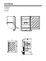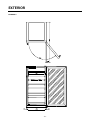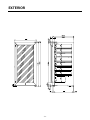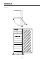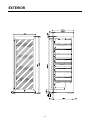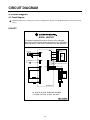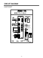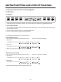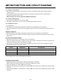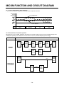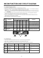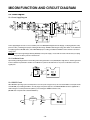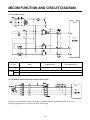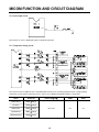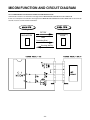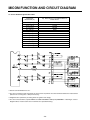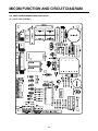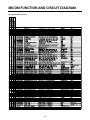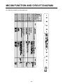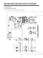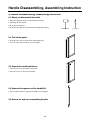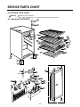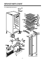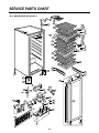
1
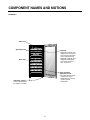
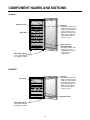
WINE CELLAR
SERVICE MANUAL
CAUTION
BEFORE SERVICING THE UNIT, READ THE "SAFETY
PRECAUTIONS" IN THIS MANUAL.
LRV410TT
LRV650TT
LRV810TT
TABLE OF CONTENTS
1. Product Specification.................................................................................................................................... 3
2. Component Names and Motions.................................................................................................................. 4
3. Exterior .......................................................................................................................................................... 7
4. Circuit Diagram ......................................................................................................................................... 12
5. Micom Function and Circuit Diagram ..................................................................................................... 14
6. Special Features
....................................................................................................................................... 30
7. Standard Self-Diagnostic Function............................................................................................................ 31
8. Maintenance ................................................................................................................................................. 32
9. Handle Disassembling, Assembling Instruction ...................................................................................... 35
10. Service Parts Chart ................................................................................................................................... 36
SAFETY INSTRUCTIONS
1. Unplug the power before you handle any electrical component.
2. If you must test the product with the power on, please wear a rubber globe in order to prevent an electric shock.
3. Check the rated current, voltage, and capacity if you are using a gauge.
4. Take caution not to let any water near the electrical component around the compressor.
5. Please use a designated part for
marked parts or the circuit diagram.
6. Please remove any object from the top prior to tilting the product.
7. In order to prevent a cut from a fin, put on a glove before you repair the refrigerator or get near the heat resistor area.
-2-
PRODUCT SPECIFICATION
1. Product Specification
1-1. Rated, product specifications
Model Name
Regular Contents
Exterior measurements
(Width X Depth X Height)
LRV410TT
LRV650TT
LRV810TT
4.7cu.ft
7.5cu.ft
9.9cu.ft
595 X 580 X 820
595 X 580 X 1185
595 X 580 X 1475
Rated Voltage/Frequency
115V / 60Hz
Power Consumption
72W
80W
85W
Weight
47kg
64kg
71kg
Cooling Method
Cool Air Automatic Circulation Type
Temperature Control Device
MICOM
Outer Case Material
Vinyl Coated Metal
Inner Case Material
A.B.S Resin
OUT DOOR
Indium Thin Oxide Triple Layers Glasses/Aluminium Deco
Insulation Material
Poly Urethane Foam (Insulation Foam Gas: Cyclopentane)
Package Exterior
Package Measurement
Details (Width X Depth X Height)
Package Weight
693 X 717 X 946
693 X 717 X 1296
693 X 717 X 1586
51kg
74kg
81kg
LRV410TT
LRV650TT
LRV810TT
1-2. Component Details
Model Name
Compressor
NR45LADG
MA53LCDG
Overload Protect
4TM232NFB
P.T.C
P220MC
P330MC
Heater
UPPER: 8W (1EA)
UPPER: 4W (2EA)
UPPER: 8W (2EA)
UPPER: 5W (2EA)
Interior Light
12V / 3W / 0.25A
Power Cord (Length)
Temperature Sensor
1.9
Heat Reducing Load Resistance Device
• Interior Heater: Heat up the interior when surrounding temperature is lower than the set temperature.
-3-
COMPONENT NAMES AND MOTIONS
2. Component Names and Motions
2-1. Interior
• Interior Light (Interior Ceiling, CASE DISPLAY & BARRIER installed in the lower column) Interior light operates by the
control panel regardless of door opening or closing.
• Interior light uses DC voltage. Please see 1-2, component details.
• 2 or 3 interior lights are installed according to model sizes and light turns on and off by control panel operation button.
2-2. Wine Rack
• Wine rack detail may vary according to the model types.
• Each rack can hold 8 wine bottles and top rack holds 9 bottles.
Model Name
LRV410TT
LRV650TT
LRV810TT
Standard Capacity
41bottles
65bottles
81bottles
2-3 Others
• Glass Holder
-Hangs wine glasses. (LRV810TT)
• Wine Rack
-Stores leftover wine (tilted). (LRV810TT, LRV650TT)
• Locking Device
-Key is enclosed in the inside of the refrigerator.
• Leg Adjustor (Front & Back, Left & Right, one each)
-Please level the product using the leg adjustor.
-4-
COMPONENT NAMES AND MOTIONS
LRV810TT
*Glass tray
Operation panel
Light bulb
• Light bulb inside the wine
fridge can be turned on or
off by pressing the button
on the operation panel.
• Light bulb inside the wine
fridge will automatically
turn off after the door is
open for an hour.
Wine shelf
Upper and lower
separation boards
• The upper board is ‘TOP’
and the lower one is
‘BOTTOM’. They can be
used to regulate
temperature.
Adjustable support
Can be adjusted when
the fridge is not stable.
-5-
COMPONENT NAMES AND MOTIONS
LRV650TT
Operation panel
Light bulb
• Light bulb inside the wine
fridge can be turned on or
off by pressing the button
on the operation panel.
• Light bulb inside the wine
fridge will automatically
turn off after the door is
open for an hour.
Wine shelf
Upper and lower
separation boards
• The upper board is ‘TOP’
and the lower one is
‘BOTTOM’. They can be
used to regulate
temperature.
Adjustable support
Can be adjusted when
the fridge is not stable.
LRV410TT
Light bulb
• Light bulb inside the wine
fridge can be turned on or
off by pressing the button
on the operation panel.
• Light bulb inside the wine
fridge will automatically
turn off after the door is
open for an hour.
Wine shelf
Operation panel
Adjustable support
Can be adjusted when
the fridge is not stable.
-6-
EXTERIOR
3. Exterior
3-1. Exterior
LRV410TT
-7-
EXTERIOR
LRV650TT
-8-
EXTERIOR
-9-
EXTERIOR
LRV810TT
- 10 -
EXTERIOR
- 11 -
CIRCUIT DIAGRAM
4. Circuit Diagram
4-1. Circuit Diagram
: Indicated component is a safety part. (In case of a replacement, please use a designated part for its function and your
safety.)
LRV410TT
MODEL: LRV410TT
This product is powered by electricity. Once the unit is unplugged,
please wait at least 5 minutes before you plug it back in. If you plug the
power right back in, it will cause a malfunction in the cooling machine.
Temperature Indicator,
Control Panel
Power Plug
Compressor
Exterior Temperature Sensor
Interior Temperature Sensor (Top)
Cooling Sensor (Top)
Interior Light
Case Display
Heater (Top)
Control Panel
Interior Light
Heater (Bottom)
BK : BLACK BL :BLUE BO : BROWN OAK BN :BROWN
YL :YELLOW PR :PURPLE GY :GRAY WH : WHITE
- 12 -
CIRCUIT DIAGRAM
LRV650TT/LRV810TT
- 13 -
MICOM FUNCTION AND CIRCUIT DIAGRAM
5. MICOM Function and Circuit diagram
5-1. Functions
5-1-1. Displays
1. At the first power-up, the machine is unlocked. And, the initial setting is 57°F/RED for top, 46 F/WHITE for bottom.
5-1-2. Lock/Unlock Function
1. By pressing the ‘Lock/Unlock’ button for 3 seconds, it will unlock the machine. If the control panel is idle for 10 second, it
will automatically lock itself.
2. 1 minute after the lock, the luminescence of the display will decrease.
3. You have to cancel the lock in order to operate the machine.
5-1-3. Setting the top/bottom parts’ storage temperature
(1) Top temperature setting
1. With the lock off, set the top storage temperature using ‘▽’, ‘△’ button on the left side of the display.
2. By pressing ‘△’
It will display in the order of 43°F
52°F
54°F
WHITE LED ON
64°F
RED LED ON
3. By pressing ‘▽’
It will display in the order of 64°F
54°F
52°F
43°F
WHITE LED ON
RED LED ON
4. NOTE: Top temperature cannot be lower than the bottom
(2) Bottom temperature setting
1. With the lock off, set the top storage temperature using ‘▽’, ‘△’ button on the right side of the display.
2. By pressing ‘△’
It will display in the order of 43°F
52°F
54°F
WHITE LED ON
64°F
RED LED ON
3. By pressing ‘▽’
It will display in the order of 64°F
54°F
52°F
43°F
WHITE LED ON
RED LED ON
4. NOTE: Bottom temperature cannot be higher than the top.
- 14 -
MICOM FUNCTION AND CIRCUIT DIAGRAM
5-1-4. DISPLAY OFF Function
1. With the lock off, by pressing the ‘Power’ button for 3 seconds, every LED turns OFF and the machine switches to
suspension mode.
2. In the suspension mode, by pressing ‘Power’ button for 3 seconds, the suspension mode is cancelled and the
Top/Bottom part displays its prior values.
NOTE: The lock is off. You can change the Top/Bottom temperature.
5-1-5. Lamp ON/OFF Function
1. Each press of the LAMP button turns on/off the LAMP.
2. If the LAMP remains turned on for over an hour, the LAMP automatically turns itself off.
5-1-6. Temperature Control
(1) Top Temperature
1. Top temperature is controlled by controlling the coolant intake valve according to the set temperature.
2. If the exterior temperature is lower than the top setting, the control increases the temperature by turning on/off the top
heater.
(2) Bottom Temperature
1. Bottom temperature is controlled by controlling the coolant intake valve according to the set temperature.
2. If the exterior temperature is lower than the bottom setting, the control increases the temperature by turning on/off the
bottom heater.
(3) 3-WAY Valve Operation Condition
1. Appropriate valve opens/closes according to each sensor temperature.
2. If both top and bottom temperature is insufficient, the part that is already in cooling process finishes its cooling, then the
other part’s valve becomes opens. (No simultaneous cooling)
3. If the cooling is not finished in given time (45min for top/30min for bottom), the parts valve in cooling process will be
closed and the other part’s valve will be opened.
Top Part
Bottom Part
Valve Operation
Satisfied
Satisfied
1)*
Satisfied
Unsatisfied
Top CLOSE / Bottom OPEN
Unsatisfied
Satisfied
Top CLOSE / Bottom OPEN
Unsatisfied
Unsatisfied
Top 45min / Bottom 30min
*1): The opposite valve of the last satisfied part will be opened.
(4) COMP Operation Condition
1. COMP will be turned on if either the top or bottom part temperature is unsatisfied.
NOTE: If EVA sensor reading is below the set temperature, COMP will not operate.
2. If both top and bottom are satisfied, COMP switches to OFF.
3. If bottom is satisfied and top is unsatisfied after a heating, COMP will not be turned on until 30 minutes after the heating
termination.
4. If top is satisfied and bottom is unsatisfied after a heating, COMP will not be turned on until 30 minutes after the heating
termination.
- 15 -
MICOM FUNCTION AND CIRCUIT DIAGRAM
5-1-7. Exterior Temperature Counter Operation
1. A sensor senses exterior temperature and keeps interior temperature constant
Wine Cellar
Storage
Temperature
Normal Operation
Exterior Temperature
Counter Operation
Seasons
Spring
Summer
Fall
Winter
5-1-8. Electronic Parts Consecutive Operation
Electronic parts, such as COMP, top/bottom, will operate in consecutive order to prevent a noise and parts damages from
multiple parts operating at an initial power-on and a series of test runs. (Includes temporary power outrage)
Function
Load Operation Order
POWER
ON
Instantly
Top
Heater
ON
3seconds
Top
Heater
OFF
0.5seconds
VALVE
Opening
3minutes
Bottom
Heater
ON
3seconds
Bottom
Heater
OFF
COMP
ON
At an initial
Power-on
3seconds
Top
VALVE
OPEN
10seconds
All
loads
OFF
7minutes
COMP
ON
Recovering from
the TEST MODE
3seconds
VALVE
Opening
- 16 -
3minutes
Left
VALVE
OPEN
MICOM FUNCTION AND CIRCUIT DIAGRAM
5-1-9. Malfunction Diagnosis Function
1. This function is to facilitate SVC at a time of a problem during an operation.
2. Even when a problem occurs, display buttons and LED will operate in normal condition. You can identify the problem by
pressing both ‘△’ and ‘▽’ button. The display will indicate the problem for 5 seconds.
NOTE: In case of a communication error, the problem will automatically be displayed on the bottom temperature
setting LED.
3. For every sensor malfunction (top, top EVA, bottom, bottom EV, Exterior sensor), all of the appropriate malfunction
indications will be displayed even when more than 2 sensors are malfunctioning.
4. In case of a communication error, the communication error has the priority. Sensor malfunction indication will not be
displayed during a communication error display.
5. Sensor malfunctions and communication error indications
Indications
NO
Malfunctions
Conditions
A part
B part
C part
D part
E part
1
Top sensor malfunction
8
E
ON
8
8
Cut wire or short circuit in top sensor
2
Top EVA sensor malfunction
E
8
ON
8
8
Cut wire or short circuit in top EVA sensor
3
Bottom sensor malfunction
8
8
ON
8
E
Cut wire or short circuit in a bottom sensor
4
Bottom EVA sensor malfunction
8
8
ON
E
8
Cut wire or short circuit in a bottom EVA sensor
5
Exterior sensor malfunction
8
8
OFF
8
8
Cut wire or short circuit in an exterior sensor
6
Communication
malfunction
OFF
OFF
OFF
C
O
No communication in 30 consecutive seconds (connector
unplugged, defected TR in communication part)
5-1-10. TEST Function
1. Test function allows PCB and product function check, and malfunctioning part identification.
2. TEST S/W is on the MAIN PCB. Test mode resumes normal operation after 2 hours.
3. After you terminate the test mode, you have to cycle the power in order to resume the normal mode.
MODE
Operation
COMP
VALVE
DISPLAY LED
TEST1
Press TEST S/W once
ON
Top valve OPEN
P1
Checking for top part’s cooling system
TEST2
Press TEST S/W once
from TEST1
ON
Bottom valve OPEN
P2
Checking for bottom part’s cooling
system
TEST3
Press TEST S/W once
from TEST2
ON
TOP 45min / Bottom
15min switchover
P3
Checking for top/bottom part’s cooling
system
Resume Each test mode resumes the initial state after two hours
Normal
Operation When resuming from the test mode, operation will activate after 5 minutes COMP delay
- 17 -
MICOM FUNCTION AND CIRCUIT DIAGRAM
5-2. Circuit Diagram
5-2-1. Power Supply Diagram
28
(VAREF)
14
3
(VASS)
Power supply diagram consists of a noise reduction part and a SIMPS(Switching Mode Power Supply), a rectifying part (BD1, CE1)
(from AC to DC), a switching part (IC3) for switching the DC voltage, TRANS for delivering the energy from Switch 1 to #2, Switch #2
for supplying power to MICOM and IC, and a FEED BACK(IC4) for sending a feedback to TRANS in order to maintain a consistent
voltage at #2.
Caution There may be high voltage electricity (DC310V) on the power supply. Please wait more than 3 minutes after you unplug
the power in order to prevent an electric shock.
5-2-2. Oscillation Circuit
Synchronizing CLOCK generation for transmitting and receiving information of IC1 (MICOM) inner logic devices, and time generation
for time calculation. If specifications of OSC1 are modified, it may alter its calculation time or may cause a malfunction. Please use
regular parts.
2
R31
1
5-2-3. RESET Circuit
When MICOM is powering up from an initial power-on or from a power outage recovery, the reset circuit initialize several parts inside
of the MICOM (C1), including the RAM. In the early stage of the power-up process, the MICOM RESET terminal is supplied with a
‘LOW’ voltage for a certain period of time (10mins). (normal voltage for RESET terminal is 5.3V)
(MICOM does not operate with a defective RESET IC)
R1
IC3
1
CC13
KIA7042AP
2
27
3
CC104
- 18 -
MICOM FUNCTION AND CIRCUIT DIAGRAM
5-2-4. Load Drive Circuit
Load Type
COMP
Top Maturing Heater
Bottom Maturing Heater
Measuring Parts (IC2)
#15
#13
#14
Condition
ON
Below 1V
OFF
12V
5-2-5. STEPPING MOTOR Operation Circuit (3-WAY VALVE)
CON6
IC6
R14
R15
R16
R17
16
15
18
17
R41
P40
P43
P42
According to a specified STEP numbers, send ‘HIGH’ and ‘LOW’ signals through MICOM PIN #16, 15, 18, and 17.
Revolving magnetism forms on the motor coil. Motor starts running.
- 19 -
MICOM FUNCTION AND CIRCUIT DIAGRAM
5-2-6. Switch Input Circuit
R18
P11
20
Input Circuit is to sense a TEST-S/W signal for refrigerator inspection.
5-2-7. Temperature Sensing Circuit
This circuit consists of top/bottom sensor, top EVA/bottom EVA sensor for controlling top/bottom parts’ storage/maturing
temperature, and an exterior temperature sensor. Each sensor’s SHORT and OPEN condition is as followed.
Sensor
Check Point
Exterior Sensor
POINT A Voltage
Top Sensor
POINT B Voltage
Bottom Sensor
POINT E Voltage
Top EVA Sensor
POINT C Voltage
Bottom EVA Sensor
POINT D Voltage
Normal (-30 ℃~50 ℃)
SHORT
OPEN
0.5 V~4.5 V
0V
5V
- 20 -
MICOM FUNCTION AND CIRCUIT DIAGRAM
5-2-8. Temperature compensation and overcooling / insufficient cooling, maturing temperature cut compensation
circuit.
(1)Temperature Compensation
R2
R3
P65 9
(AIN5)
UCR1
P66 10
(AIN6)
LCR2
A circuit to input a value of compensation temperature to MICOM for controlling top/bottom storage temperature
Top
Bottom
(RCT)
(RCB)
Value of temperature
compensation
Others
180 ㏀
+2.5 °C [+4.5 °F]
56 ㏀
+2.0 °C [+3.6 °F]
Compensation to
warm up
33 ㏀
+1.5 °C [+2.7 °F]
18 ㏀
+1.0 °C [+1.8 °F]
12 ㏀
+0.5 °C [+0.9 °F]
10 ㏀
0 °C [+0 °F]
8.2 ㏀
-0.5 °C [-0.9 °F]
5.6 ㏀
-1.0 °C [-1.8 °F]
3.3 ㏀
-1.5 °C [-2.7 °F]
2㏀
-2.0 °C [-3.6 °F]
470 Ω
-2.5 °C [-4.5 °F]
Standard Temperature
Compensation to
cool down
4 Temperature compensation chart according to a resistance value change (Value differences by current temperature)
Ex) Top Resistance Compensation (RCT) 10K(Current Resistance) → 18K(Modified Resistance) = Top Temperature +1 ˚C
Modified
Classification CurrentResistance
470 Ω
2㏀
3.3 ㏀
5.6 ㏀
8.2 ㏀
10 ㏀
12 ㏀
18 ㏀
33 ㏀
56 ㏀
180 ㏀
Resistance
Top
(RCT)
Bottom
(RCB)
470 Ω
No Change 0.5 ℃Increase 1 ℃Increase 1.5 ℃Increase 2 ℃Increase 2.5 ℃Increase 3 ℃Increase 3.5 ℃Increase 4 ℃Increase 4.5 ℃Increase 5 ℃Increase
2㏀
0.5 ℃Decrease No Change 0.5 ℃Increase 1 ℃Increase 1.5 ℃Increase 2 ℃Increase 2.5 ℃Increase 3 ℃Increase 3.5 ℃Increase 4 ℃Increase 4.5 ℃Increase
3.3 ㏀
1 ℃Decrease 0.5 ℃Decrease No Change 0.5 ℃Increase 1 ℃Increase 1.5 ℃Increase 2 ℃Increase 2.5 ℃Increase 3 ℃Increase 3.5 ℃Increase 4 ℃Increase
5.6 ㏀
1.5 ℃Decrease 1 ℃Decrease 0.5 ℃Decrease No Change 0.5 ℃Increase 1 ℃Increase 1.5 ℃Increase 2 ℃Increase 2.5 ℃Increase 3 ℃Increase 3.5 ℃Increase
8.2 ㏀
2 ℃Decrease 1.5 ℃Decrease 1 ℃Decrease 0.5 ℃Decrease No Change 0.5 ℃Increase 1 ℃Increase 1.5 ℃Increase 2 ℃Increase 2.5 ℃Increase 3 ℃Increase
10 ㏀
2.5 ℃Decrease 2 ℃Decrease 1.5 ℃Decrease 1 ℃Decrease 0.5 ℃Decrease No Change 0.5 ℃Increase 1 ℃Increase 1.5 ℃Increase 2 ℃Increase 2.5 ℃Increase
12 ㏀
3 ℃Decrease 2.5 ℃Decrease 2 ℃Decrease 1.5 ℃Decrease 1 ℃Decrease 0.5 ℃Decrease No Change 0.5 ℃Increase 1 ℃Increase 1.5 ℃Increase 2 ℃Increase
18 ㏀
3.5 ℃Decrease 3 ℃Decrease 2.5 ℃Decrease 2 ℃Decrease 1.5 ℃Decrease 1 ℃Decrease 0.5 ℃Decrease No Change 0.5 ℃Increase 1 ℃Increase 1.5 ℃Increase
33 ㏀
4 ℃Decrease 3.5 ℃Decrease 3 ℃Decrease 2.5 ℃Decrease 2 ℃Decrease 1.5 ℃Decrease 1 ℃Decrease 0.5 ℃Decrease No Change 0.5 ℃Increase 1 ℃Increase
56 ㏀
4.5 ℃Decrease 4 ℃Decrease 3.5 ℃Decrease 3 ℃Decrease 2.5 ℃Decrease 2 ℃Decrease 1.5 ℃Decrease 1 ℃Decrease 0.5 ℃Decrease No Change 0.5 ℃Increase
180 ㏀
5 ℃Decrease 4.5 ℃Decrease 4 ℃Decrease 3.5 ℃Decrease 3 ℃Decrease 2.5 ℃Decrease 2 ℃Decrease 1.5 ℃Decrease 1 ℃Decrease 0.5 ℃Decrease No Change
- 21 -
MICOM FUNCTION AND CIRCUIT DIAGRAM
5-2-9. Communication Circuit between MAIN PCB and DISPLAY PCB
Communication circuit for an information exchange between MAIN MICOM and DISPLAY PCB in MAIN PCB
If there is an interruption in information exchange between MAIN MICOM and DISPLAY PCB in MAIN PCB for more than 30
seconds, it causes a communication malfunction.
MAIN PCB
DISPLAYPCB
DC 12V
LCD Controlling
MICOM
MAIN MICOM
GND
Transmitting (Error)
Receiving (NOTCH)
- 22 -
MICOM FUNCTION AND CIRCUIT DIAGRAM
5-3. Sensor Resistance Specification Chart
Temperature
Measurement (°C)
Top · Bottom Sensor, Top · Bottom EVA Sensor,
Exterior Sensor
-20 °C [-4 °F]
-15 °C [+5 °F]
-10 °C [+14 °F]
-5 °C [+23 °F]
0 °C [+32 °F]
+5 [+41 °F]
+10 [+50 °F]
+15 [+59 °F]
+20 [+68 °F]
+25 [+77 °F]
+30 [+86 °F]
+40 [+104 °F]
+50 [+122 °F]
77 KΩ
60 KΩ
47.3 KΩ
38.4 KΩ
30 KΩ
24.1 KΩ
19.5 KΩ
15.9 KΩ
13 KΩ
11 KΩ
8.9 KΩ
6.2 KΩ
4.3 KΩ
Exterior Sensor
Top Sensor
Top EVA Sensor
Bottom EVA Sensor
Bottom
Sensor
4 Sensor Common Difference is 5%.
4 For sensor resistance value measuring, the sensor must stay idle for more than 3 minutes before the measurement.
(Because of a sensing rate, a delay is necessary)
4 A digital tester is preferred. (an analog tester has greater error range)
4 For sensor measurement, separate MAIN Part CON4 HOUSING in PWB (PCB) ASSEMBLY. Referring to a circuit
diagram above, measure each sensor’s terminal at a separated housing.
- 23 -
MICOM FUNCTION AND CIRCUIT DIAGRAM
5-4 MAIN PWB ASSEMBLY AND PARTS LIST
5-4-1 MAIN PWB ASSEMBLY
- 24 -
MICOM FUNCTION AND CIRCUIT DIAGRAM
5-4-2 Replacement Parts List
- 25 -
MICOM FUNCTION AND CIRCUIT DIAGRAM
5-4-3 PWB ASS’Y, DISPLAY AND PARTS LIST
°F
°C
°F
°C
- 26 -
MICOM FUNCTION AND CIRCUIT DIAGRAM
5-5 PWB DIAGRAM
5-5-1 PWB Assembly Main DIAGRAM
(* PWB circuit diagram may vary a little bit depending on actual condition.)
- 27 -
MICOM FUNCTION AND CIRCUIT DIAGRAM
- 28 -
MICOM FUNCTION AND CIRCUIT DIAGRAM
5-5-2 PWB Assembly DISPLAY DIAGRAM
(* PWB circuit diagram may vary a little bit depending on actual condition.)
- 29 -
SPECIAL FEATURES
6. Special Features
6-1. Direct cooling system prevents sudden temperature change
An evaporator (laid inside of the back panel) prevents a sudden temperature change. The interior sensor located in the
upper/lower part divider controls the temperature, matching the interior and the actual wine temperature. Interior
temperature can be adjusted in a range between 6~18 °C. (1 unit = 1 deg).
6-2. ITO triple layer glass blocks ultraviolet and
infrared rays. It is a frost free glass.
ITO (Indium Thin Oxide) glass has 86% of infrared
rays reflection and 20% of ultraviolet rays
transmission. The glass can be reinforced,
preventing any injury from an exterior impact. Also,
the heat resistant quality of ITO glass prevents any
frost forming.
Reflected light
Incident light
Ultraviolet rays: 80%
Infrared rays: 86%
Heat reflector
processed surface
Argon gas
Transmitted light
6-3. Low vibration / Anti-vibration structure
Vibration causes convection in precipitations on the bottom of the wine bottle, resulting in a wine heat up by an over-aging.
Low vibration/Anti-vibration structure reduces vibrations from the compressor. This supports maintains the wine taste for a
longer period of time. Also, the leg adjustor function was added in order to reduce vibration.
- 30 -
STANDARD SELF-DIAGNOSTIC FUNCTION
7. Standard Self-Diagnostic Function
In case if there is any malfunction in the wine cellar, a symbol automatically is indicated on the “set temperature” display.
Symbol explanation is on the circuit diagram on the back panel of the product.
7-1. Indications
Symbol
UU/UU
*EE/88
*88/EE
Check point
Symptom/Condition
Cause
Solution
Over-cooling and weak-cooling in upper
and lower part at the same time
Insufficient cooling in upper and lower part
Operation malfunction and OLP activated
VALVE
Improper coolant valve location
Capillary tube welding clogged
Improper coolant valve
operation
Replace Valve
VALVE PIPE welding
clogged
Insufficient cooling in upper part
Upper part interior sensor
Sensor line cut
Replace Case display
Upper part cooling sensor
Sensor malfunction
Lower part interior sensor
Sensor line cut
Lower part cooling sensor
Sensor malfunction
Display PWB lead wire
Cut wire, PWB malfunction
Replace Case display
Upper part interior sensor
Sensor line cut
Replace Case display
Insufficient cooling in lower part
CO/- -
Improper communication in display
*8E/88
Insufficient cooling in upper part
Switch valve terminal location
Replace barrier
Sensor malfunction
*88/8E
*E8/88
*88/E8
NOTE)
Insufficient cooling in lower part
Insufficient cooling
Weak cooling/overcooling malfunction
Lower part interior sensor
Sensor line cut
Lower part cooling sensor
Sensor malfunction
Upper part cooling sensor
Sensor line cut
Lower part cooling sensor
Sensor malfunction
MAIN PCB
Cut wire or a short circuit in the
exterior sensor
Replace barrier
-Product Exchange
If ‘ * ’ indication appears, press both of the upper part temperature control switch (‘▽’, ‘△’)at the same time.
NOTE) Turns off ‘RED’ and ‘WHITE’ LED of TOP and BOTTOM.
7-2. Presentation Mode
This function was added for salesroom display
1. Turn on the power and press both temperature increase
key (on the left side) and the ‘lamp’ (on the right side)
button at the same time for 5 seconds.
3. The compressor and the heater operation will be
interrupted. Temperature control and lamp function will
be in normal operation.
4. If you want to cancel the presentation mode, follow the
same instruction from number 1. Normal cooling mode
will resume.
* In case of a power outrage, the presentation mode
automatically cancels itself. Resetting is required.
2. ‘SHOP’ or ‘SH’ displays for 3 seconds, then, the normal
temperature display comes up
- 31 -
MAINTENANCE
8. Maintenance
8-1. Installation Instruction
(Leveling the product)
(Ensuring heat radiation area)
Two people are required in order to perform the leveling.
The heat radiation grill emits heat. Please leave enough
space, more than 10cm for top, and 0.5cm for left and right
side, for heat radiation area.
1. Tilt the product a little bit to the back.
2. Level the product using
the leg adjustor. (Front
& Back, Left & Right,
one each)
Leg adjustor
(Avoid a heat and direct sunlight when installing the
product)
(Install the product in a dry and well ventilated space)
It may form a mold, resulting in a high electric bill
It may decrease the cooling power, resulting in a high
electric bill
8-2 Cleaning Instruction
Before cleaning, make sure that the power is unplugged and clean the interior once a year.
1. Unplug the power.
2. Please use a soft cloth dampened with water or a detergent for exterior. If you are using a neutral detergent, wash it off
with a clean wet towel.
3. Do not use a polishing agent or a thinner.
4. Do not pour water in the interior or on the exterior.
5. Unclean door packing causes cool air leakage. Please clean it properly.
6. After the cleaning, place the parts in its original place. Plug in the power and set a desired temperature.
- 32 -
MAINTENANCE
8-3. Temperature control
The regulated temperature range is 43°F to 64°F
Lock/Unlock Function
To change the temperature,
press the button for 3 seconds.
Power button
Press to turn ON,
Press and hold 3 seconds
to turn OFF
Light Switch
Push for ON, Push again for OFF
Indication of “BOTTOM” (Light wil automatically turn off
set temperature
after one hour.)
Indication of “TOP”
set temperature
“TOP” temperature
control button
Indication of wine
category
“BOTTOM” temperature
control button
Change the Temperature
Default (factory) setting is 57°F for the upper section and for model LRV410TT; the lower section is 46°F.
Press “Hold ” button for 3 seconds.
In the unlocked state, the temperature indicators blink.
* Children should be restricted from tampering with the “Hold”
button to avoid causing unwanted changes.
After the temperature is set, press the “Hold” utton again.
The indicator will be on, showing the temperature has been
set.
For best results, select a temperature setting in the range
specified for each type of wine.
RED
WHITE
Each press of an upper or lower temperature button will
raise or lower the temperature by 1°F.
54°F~64°F
43°F~52°F
To change the temperature display from °C to °F or °F to °C,
press the “Hold” and “Light” buttons simultaneously for 3
seconds.
Storage Temperature for wine
• Note that the temperature of the upper section cannot be set colder than the lower section.
If you want to adjust the upper section below the current temperature of the lower section, it is necessary to first lower the
temperature in lower section.
• When it is delivered, the temperature is set to RED (57°F) for upper shelf, and WHITE (46°F) for lower shelf.
• The recommended temperature range for wine is:
WHITE 43°F~52°F
RED 54°F~64°F
• The time for the interior temperature to reach the set temperature varies with the specific usage of the refrigerator.
• The displayed temperature is the set temperature, which may be different from the actual temperature of the wine stored in
the refrigerator.
• After a power outage, temperature resetting is needed. Resetting can be done in accordance with instructions in
‘Temperature Setting during Installation’.
- 33 -
MAINTENANCE
8-4. Correct Usage
8-4-1. How to place the wine bottle?
* When placing in the wine bottle, please place bottles inserting direction
crossing each other as shown as in the picture.
* If you overload one shelf, it may cause inconvenience when you take out
the bottle. It may also cause damage to the shelf.
8-4-2. Long term storage (LRV810TT)
* For a leftover wine, store it with its lid tightly shut
* Precipitations may form on the bottom of the wine bottle according to wine
variety, storage condition, and storage length. This is only natural.
8-4-3. Bottom shelf storage
* Bottom shelf can hold 4 bottles, maximum 9 bottles.
9 BOTTLES
AT THE
MAXIMUM
BOTTOM
SHELF
4 BOTTLES
- 34 -
Handle Disassembling, Assembling Instruction
9. Handle Disassembling, Assembling Instruction
9-1. Before you disassemble the handle.
1. Empty the refrigerator before you disassemble the handle.
2. Following tools are required.
3. Do not tilt the refrigerator.
4. Be careful not to drop the handle when disassembling/assembling.
Rubber hammer
9-2. Take off the gasket.
1. Be careful not to tear the gasket when separating the part.
2. It is much easier if you pull the corner of the gasket.
9-3. Separate the handle and the bar.
1. Take out 3 screws on the bottom of the handle.
2. Take out 3 screws on the top of the handle.
9-4. Separate the supporter and the handle(U/L).
1. Use the rubber handle for supporter and handle (U/L) separation.
9-5. Reverse the order for re-assembling the parts
- 35 -
(+), (-) Driver.
SERVICE PARTS CHART
10. Service Parts Chart
Indicated is a safety component.
(When replacing the part, please use a designated part for your safety and its function.)
Warning
10-1. Spread sheet 1(LRV410TT)
281A
281B
281E
409B
C
136A
120D
409B
120D
11
10C
503B
6
109H
5
103F
136B
136A
136C
136B
283B
106A
106B
283D
106A
281F
319C
230A
244E
2 30A
317A
318
8A
314A
233A
31
307A
316B
308A
606E
501K
K
309A
310A
327A
316A
328B
312A
501A
244A
501F
315A
305A
243A
244E
- 36 -
SERVICE PARTS CHART
10-2. Spread sheet 2(LRV650TT)
281A
281B
136A
281E
409B
C
409B
120D
136A
120D
11
10C
5
103B
B
136A
149B
136A
9
11
10C
609H
503F
409B
B
120D
136A
136C
145D
283B
106B
128D
145C
106A
281F
283D
128C
230A
244E
2 30A
106A
233A
319C
619A
317A
319A
314A
318A
307A
316B
308A
606E
501
K
309A
310A
327A
316A
244A
328B
312A
501A
501F
315A
305A
243A
244E
- 37 -
SERVICE PARTS CHART
10-3. Spread sheet 3(LRV810TT)
281A
136H
136M
136A
281B
409B
120D
136A
11
10C
281E
409B
C
503B
B
136A
120D
609H
503F
409B
B
120D
136A
9
11
10C
136A
155D
136A
136A
136C
145D
283B
128D
145C
106B
106A
128C
281F
283D
230A
244E
2 30A
106A
233A
319C
619A
317A
319A
314A
318A
307A
316B
308A
606E
501
K
309A
310A
327A
316A
244A
328B
312A
501A
501F
315A
305A
243A
244E
- 38 -
P/No. 3828JD8886A
JUL., 2005 Printed in Korea