1
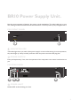
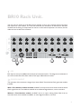
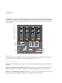
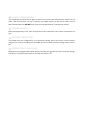
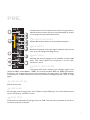
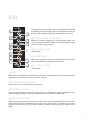
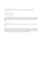
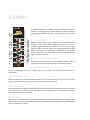
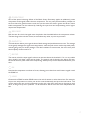
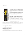
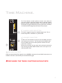
User Manual
Version 1.4
Contents.
Safety Information.���������������������������������������������������������������������������������������������������� 3
Installing Modules������������������������������������������������������������������������������������������������������ 4
Welcome.������������������������������������������������������������������������������������������������������������������� 5
BR10 Power Supply Unit.������������������������������������������������������������������������������������������ 6
BR10 Rack Unit.��������������������������������������������������������������������������������������������������������� 8
BB4...........................................................................................................................10
PRE.�������������������������������������������������������������������������������������������������������������������������� 12
EQ.���������������������������������������������������������������������������������������������������������������������������� 14
COMP.���������������������������������������������������������������������������������������������������������������������� 16
ADC.������������������������������������������������������������������������������������������������������������������������ 18
Time Machine..................................................................................................... 20
Warranty.����������������������������������������������������������������������������������������������������������������� 21
2
Safety Information.
!
WARNING
THIS EQUIPMENT MUST BE EARTHED.
DO NOT EXPOSE TO RAIN OR MOISTURE.
EARTH
This unit is connected via its power cord to the mains safety earth. NEVER OPERATE THE UNIT
WITH THIS EARTH CONNECTION REMOVED.
COVERS
DO NOT remove the covers. Refer servicing to qualified personnel only.
VOLTAGE
Your Black Series System is set to operate at either 115 or 230 Volts, as indicated on the rear panel.
Ensure that your Black Series System is correctly rated for the country of operation.
FUSES
CHECK that the fuse fitted is of the correct type for the local mains voltage. ALWAYS replace fuse
with the correct type. For 230 Volts, use T1.6A slowblow type. For 115 Volts, use T3.15A slow-blow
type.
MOISTURE
DO NOT expose the unit to rain or moisture. If any part of your Black Series System should become
so exposed, REMOVE the mains power immediately.
HEAT
ALWAYS site your Black Series System away from sources of heat including direct sunlight and
ensure adequate ventilation around the unit.
Regulatory Compliance
This product complies with both the EMC Directive (89/33 6/EEC) and the Low Voltage Directive
(73 /23 /EEC) as issued by the Commission of the European Community. Compliance with these
directives imply conformity with the following European standards:
• EN60065 Product safety
• EN55103-1 Electromagnetic Interference (Emission)
• EN55103-2 Electromagnetic Susceptibility (Immunity)
3
Installing Modules
Do not open the covers, remove or install modules
unless the rack unit is completely isolated from the
mains supply.
Empty Slots must be covered with blank panels
when the Rack is powered
The rear side of each Black Series module has a DIN41612 connector, allowing it to access power
and audio connections from the Rack. Follow this procedure to install a new module.
Isolate the rack unit from the mains by detaching the power cable.
Remove the desired blanking panel from the rack front.
Take the module to be inserted, trying to minimise contact with the circuit board, and slot into
the bay.
At the rear of the unit, the module's DIN41612 connector should meet with a mating connector
on the rack back-plane. Once aligned, these should guide each other to create a snug fit.
Replace screws.
Do not force the module. Instead, take the module out and have a look for the slot you're
aiming for. If you can, it may help to remove the neighbouring blanking panels to get a better view.
Modules are sensitive to static. Ensure you are in
contact with earthed metalwork before handling
modules and do not walk across carpet holding
them.
4
Welcome.
Thank You
Thank you for buying this Audient product. We hope your Black Series System will bring you years
of fruitful sound sculpting, smoothing, designing and destruction.
5
BR10 Power Supply Unit.
Not the most interesting of devices, but pretty crucial nonetheless. This little buddy sits in your
rack, dishing out Watts to whatsoever should need them. The front panel is pretty straightforward:
PSU Front Panel
Indicator LEDs
These little lights show you which of the power supply’s circuits are functioning. In normal operation,
they will all light up. If they’re all off, you’d best check the power switch and the plug fuse.
Power Switch
Pretty self-explanatory. If not, then the operation of the compressor ratio control could be lost on
you.
PSU Rear Panel
230
FUSE
Power Inlet
Standard IEC socket. Nothing new here.
6
Fuse
As you've probably guessed, the fuse goes in here. Be sure to select the right fuse for your local
mains voltage. Use 20mm T-type slow-blow fuses; 1.6A for 230V and 3.15A for 115V.
Voltage Selector
This should come pre-configured for your local mains voltage, but be sure that it is correct before
using the unit. If you're travelling with your Black Series Rack, be sure to check the mains voltage
where you are, too.
Power Cable
1.5m cable with a Neutrik PowerCon on the end of it. Yes, it looks like a loudspeaker plug. It’s not.
Trust us. And please don’t try putting it into a speaker. Thanks.
Now that you’re all powered up, we can take a look at the business end of the system...
7
BR10 Rack Unit.
The rack unit can house up to 10 Black Series modules. It has a rear connector panel with inputs
and outputs for each module. The rack also facilitates the distribution of Word Clock between
modules and the linking of compressors for stereo or multi-channel operation. Let’s face it, the less
cables we have to deal with, the better.
I/O
Each bay has two inputs (A&B) and one output (C) associated with it. The diagram at the bottom of
the rack unit illustrates how these relate to each type of Black Series module.
Clock In/Out
The operation of this connector changes if you have a Black Time Machine Clock generator module
installed:
With a Time Machine module installed, the BNC is an output and can be used to send the Word
Clock signal from the Time Machine module out to additional digital devices, such as recorders.
Without a Time Machine module, the BNC acts as an input, making Word Clock from an
external master clock available to all ADCs, or other digital modules, in the rack.
8
Clock Terminator
This terminates the Word Clock signal to ensure that clock pulses don't bounce around on the
cable. That would be bad. Use this if, and only if, the Black Series Rack is at the end of a daisy-chain
of Word-Clocked devices. DO NOT use if you're using a Black Series Time Machine module.
PSU Input
This is the input from the PSU. No, it won't work if you attach a power-amplifier to it. ONLY attach
the power cable of an Audient Black Series PSU to this connector.
B Inputs
This handy D-Sub gives you access to the B inputs of modules 1-8, so you can cable it up nicely. This
25-pin female connector follows Tascam DA88 analogue standard wiring.
C Outputs
Another handy D-Sub, this time to connect to the C outputs of modules 1-8. Great for hooking up
to a recorder. This 25-pin female connector follows Tascam DA88 analogue standard wiring.
9
BB4
The BB4 unit can house up to 4 Black Series modules. It has a rear connector panel with inputs and
outputs for each module. The unit also facilitates the distribution of Word Clock between modules
and the linking of compressors for stereo operation. Let’s face it, the less cables we have to deal
with, the better.
A
B
C
I/O
Each bay has two inputs (A&B) and one output (C) associated with it. The diagram at the bottom of
the unit illustrates how these relate to each type of Black Series module.
Clock In/Out
The operation of this connector changes if you have a Black Time Machine Clock generator module
installed:
With a Time Machine module installed, the BNC is an output and can be used to send the Word
Clock signal from the Time Machine module out to additional digital devices, such as recorders.
Without a Time Machine module, the BNC acts as an input, making Word Clock from an
external master clock available to all ADCs, or other digital modules, in the rack.
10
Clock Terminator
This terminates the Word Clock signal to ensure that clock pulses don't bounce around on the
cable. That would be bad. Use this if, and only if, the Black Series is at the end of a daisy-chain of
Word-Clocked devices. DO NOT use if you're using a Black Series Time Machine module.
Power Switch
Pretty self-explanatory. If not, then the operation of the compressor ratio control could be lost on
you.
Voltage Selector
This should come pre-configured for your local mains voltage, but be sure that it is correct before
using the unit. If you're travelling with your BB4, be sure to check the mains voltage where you are,
too.
Power Inlet and Fuse
IEC Socket with integrated fuse holder. Be sure to select the right fuse for your local mains voltage.
Use 20mm T-type slow-blow fuses; 1A for 230V and 2A for 115V.
11
PRE.
The Black series Pre is the perfect front-end for any application; a
delicate balance of classic character with the flexibility of modern
circuit design and renowned Audient clarity.
Phantom Power
Applies 48V Phantom Power to the attached microphone.
Polarity
Reverses the polarity of the input signal. Handy for bottom snare
mics, or for correcting some dodgy wiring…
Mic Gain
Switched gain control ranging from 10 to 60dB in constant 10dB
steps. This control affects the microphone or the DI input,
whichever is active.
Black
Input Level Meter
12-segment LED meter measuring the analogue output level,
relative to 0dBFS, where 0dBFS= +18dBu. This matches the Black ADC unit. 0dBFS (FS stands for
Full Scale) is the maximum level that can be represented by the digital signal. The ‘OVER’ indicator
will illuminate at +1dBFS. Note that this does not indicate the analogue clip point, which is 3-4dB
higher.
Line Selector
Selects the line input.
Line Gain
Switched gain control ranging from -10 to+15dB in constant 5dB steps. This control affects the line
input or the DI input, whichever is active.
Gain Trim
Continuous fine-adjustment of input gain from 0 to 10dB. This control acts in addition to the Mic or
Line Gain, whichever is selected.
12
High-Pass Filter
A 12dB/Octave filter, variable from 30 to 225Hz. Great for eliminating microphone stand rumble,
air conditioning noise, or thundering bass from the room next door.
High-Pass Filter In
Switches the filter in and out of circuit, allowing you to hear its impact.
HMX
Telling you that this adds another solid state triode gain stage configured to enhance low order
harmonics really doesn’t convey how cool it is. And saying that it sounds like an egg screaming won’t
help much either. So, press the button and find out for yourself. 0 means none, and 10 means lots,
but that’s it.
HMX In
HMX In, HMX Out. Egg screaming. Egg hushed.
Inst/DI Input
A handy, front panel socket for a Theremin, Chapman Stick, electric spoons, or even a guitar.
Plugging in here overrides the other inputs. The DI input’s gain can then be controlled by either the
mic or line gain controls, whichever is selected. This lets you choose the gain range and step size
that best suits your chosen instrument.
13
EQ.
The Black EQ puts the magic back into equalisation. An intuitive
4-band EQ, plus a smattering of great creative features to let you
smooth, sculpt, design and destroy; whatever takes your fancy.
HF Shelving Frequency
Selects the turnover frequency of the high shelving filter. You
can choose between 8kHz and AIR, a very high-frequency shelf,
which you’d best try for yourself.
HF Shelf Gain
±15dB of gain.
Overtone
Adds a nice sprinkle of harmonic enhancement to the LF band
only, proportional to the amount of LF cut/boost.
LF Shelf Gain
±15dB of gain.
Glo
Boosts then compresses the low frequency side-chain, enhancing the low-end while dynamically
controlling the low frequency content. Try it for yourself.
Presence Frequency
Selects either 1.5 or 3kHz as the centre frequency.
Presence Gain
A great tool for helping a sound cut through the mix, or blend subtly into the background. This
control swings both ways, so you can get absence as well as presence! ±15dB range.
Presence Shape
When this button is pushed in, boost and cut both act over the same bandwidth. Out, the presence
control boosts across a broad band, and cuts only a very narrow band. This reflects your natural
response to EQ and allows you to make corrective changes without altering the essence of the
signal.
14
Lo Mid Frequency
This variable frequency control allows you to pinpoint frequencies from 125Hz to 2kHz.
Lo Mid Gain
±15dB of low-mid loveliness.
Lo Mid Shape
When this button is pushed in, boost and cut both act over the same bandwidth. Out, the presence
control boosts across a broad band, and cuts only a very narrow band. This reflects your natural
response to EQ and allows you to make corrective changes without altering the essence of the
signal.
EQ In/Out
Allows you to A/B the signal and hear how much better the EQ has made it. This doesn't affect tilt
though.
Tilt
A great way to alter the tonal balance of a signal quickly and intuitively. In its centre position,
nothing happens (boo). Switched to the either side, two broad shelving filters are applied, ‘tilting’
the spectrum towards the top or bottom end. To the left gets you more bottom and less top, and
vice‑versa to the right. Tilt pivots around 1kHz, with ±2dB at the extremes.
15
COMP.
The Black COMP is a flexible, classic-sounding compressor,
capable of everything from gentle dynamic control to full-on
thumping gain reduction. We can't wait to hear what you do with
it...
VU Meter
Displays output level or gain reduction, as determined by the
‘METER’ switch, below. When displaying output level, 0VU =
+4dBu. For gain reduction, the meter will rest at 0, and swing to
the left as gain is reduced. COMP has a fixed threshold of around
-20Bu; the amount of compression is controlled by the balance
of input attenuation and output gain, i.e. more input attenuation,
higher effective threshold.
Input Attenuation
Controls input attenuation from –30 to 0dB. In tandem with the
output gain control, this has the effect of a threshold control.
Output Gain
Controls output gain from 0 to +30dB. Allows you to adjust for the gain-reducing effects of
compression.
Meter Switch
Selects whether the meter indicates gain reduction or output level. With the switch out the meter
indicates gain reduction, with the switch depressed it shows output level.
Sidechain
Switches the sidechain signal between the input source and the external sidechain source, connected
to the A connector on the rear panel. This allows you to change what the compressor is listening to
and, consequently, how it responds.
Attack
Sets the time for which an input signal must be above the threshold level before reducing gain. Fast
attack times will help to control transient peaks, while slower times will tend to sound smoother,
with less tendency to ‘pump’.
16
Overcomp
One of the special colouring effects of the Black Series, Overcomp applies an additional, preset
compressor to the signal, before the main compressor. This is a pretty extreme effect; perhaps not
the first choice for gentle acoustic vocals, but just the ticket for electric guitars and drums. More
subtle compression can be achieved by reducing the input level and compensating with a higher
output level. Experiment!
Release
Sets the time for which the signal must drop below the threshold before the compressor relaxes.
The best thing to do with this control, as with almost any other, is just trust your ears!
Smooth
This little button allows you to get the best of both average and peak detection circuits. The average
circuit gently massages the signal with compression, while the peak circuit catches wayward peaks,
without going crazy on louder passages. This does wonders to stereo mixes, but we’re sure you’ll
think of plenty of other uses for it.
Ratio
The ratio at which the input signal’s volume can increase above the threshold. 1.2:1 is a very subtle
ratio, while 8:1 will keep a tight hold on levels. The general rule of thumb is: the higher the ratio,
the less of the time you’ll want to be compressing, so keep an eye on the G/R meter and trust your
ears.
In
Switches the compressor in and out of circuit, allowing you to hear how much better a signal is with
the COMP in!
Link
Connects the COMP to other COMP units in the rack for stereo or multi-channel use. For example,
to pair two compressors in stereo, just set the controls identically and press the link button. This
can be used to link any and all compressors in the rack; they don’t even have to be next to each
other, so long as they are in positions 1 to 8. Positions 9 and 10 have their own independent link
bus.
17
ADC.
The ADC module provides ultra high quality stereo analogue to
digital conversion. Outputs are on AES/EBU and both optical and
co-axial SPDIF. Sample rates from 44.1 to 192kHz are available on
all outputs.
Word Clock may be generated by the ADC internally, or received
via the rack’s Clock connector. Word Clock can also be received
inside the rack from a Black Series Time Machine module.
Input Level Meter
12-segment LED meter measuring the analogue input level,
relative to 0dBFS, where 0dBFS = 18dBu. Internal jumpers are
available to optionally set the 0dBFS level to +20,+22, +24 dBu.
0dBFS (FS stands for Full Scale) is the maximum level that can
be represented by the digital signal. Input levels in excess of this
will be clipped severely and, ostensibly, sound pretty rough. The
‘OVER’ indicator will illuminate at +1dBFS. Unlike with analogue
equipment, this light should be avoided at all costs.
Sample Rate Selector
Pressing the Sample Rate selector cycles through each of the available internal sample rates before
looking to an external Word Clock source. For each of the internal sample rates, a yellow LED will
indicate the selected rate. When the external Word Clock input is selected, the ‘LOCK’ light will
flash until the signal is locked, at which point it will glow steadily.
Optical SPDIF Output
SPDIF over lightpipe.
Coaxial SPDIF Output
SPDIF over good-old copper coaxial cable.
AES/EBU Output
Duplicates the AES/EBU socket on the rear of the rack, but is not electrically isolated from it.
18
Time Machine.
The Time Machine module performs master clock duties for
your entire studio, supporting sample rates of 44.1kHz, 48kHz,
88.2kHz, 96kHz, 176.4kHz and 192kHz. The Word Clock signal is
distributed through the Black Rack and rear panel clock connector
via a dedicated bus designed specifically for this purpose.
Sample Rate Selector
This button toggles through the available sample rates. The selected sample rate is indicated via a yellow LED.
Source Selector
To allow the Time Machine to output to the rear BNC connector
this must be set to internal. This will synchronise all ADC modules in the Black Series rack and any devices slaved to the rear
panel clock connector.
When set to external, the rear panel clock connector becomes an
input, allowing any Black ADC modules in the rack to sync to an
external master clock.
AES/EBU Output
Used to transmit Word Clock signals over an AES/EBU connection where a BNC connection is not
available. No audio is transmitted, just the Word Clock signal.
Disclaimer: Time travel functions in public Beta
19
Warranty.
Your Black Series System has been manufactured to a high standard using quality components. If
correctly installed and operated the unit should give years of problem free operation. However in
the event of a defect in material or workmanship causing failure of the unit within 1 year of the date
of original purchase we will agree to repair, or at our discretion replace, any defective item without
charge for labour or parts. To receive service under this warranty it is necessary to return the unit
to an Audient authorised service centre or to the factory with a dated receipt as proof of purchase.
After repair the unit will be returned to you free of charge.
Limitations:
This warranty does not cover damage resulting from accident or misuse. The warranty is void unless
repairs are carried out by an authorised service centre. The warranty is void if the unit has been
modified other than at the manufacturers instruction. The warranty does not cover components
which have a limited life, and which are expected to be periodically replaced for optimal
performance. We do not warrant that the unit shall operate in any way other than as described in
this manual.
20