1
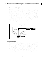
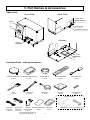
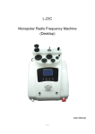
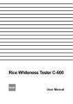
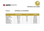
Powder Whiteness Tester C-130
User Manual
Safety Precautions
If this whiteness tester is not used according to the safety precautions, accidents can
occur which may cause damage to the instrument, the operator or other items. Our
design has included substantial consideration for product safety but please ready the
precautions contained in this user manual and use the product correctly.
■
Please obey all safety precautions
Please thoroughly read the precautions included in the user manual.
■
Please do not use this product if it is not working properly
If the product should break or malfunction, please contact the retail outlet where
you purchased the product, or our company directly.
■
Interpreting warning symbols
The following symbol is displayed in this user manual to help prevent accidents from
occurring due to the incorrect use of this device.
This symbol indicates that, if ignored, and if the device is incorrectly used, physical
Caution
damage or user injury may occur.
Table of Contents
1. Measurement Principles and Characteristics.....................................4
2. Specifications.........................................................................................5
3. Part Names & Accessories....................................................................6
4. Description of Operation Keys..............................................................7
5. Preparing for Measurement...................................................................8
6. Measurement..........................................................................................9
7. How to Make User Calibration Curve....................................................12
8. Maintenance & Other Functions...........................................................15
1. Measurement Principles and Characteristics
■ Measurement Principles
This device measures powder whiteness according to our own uniquely
developed standards. It measures reflectivity and utilizes two blue LEDs as its
light source. The light from the blue LEDs is passed through a diffuser panel and
shined onto the sample surface at 45 degree angles from both the left and right.
A photo diode measures the amount of reflected light. The whiter the sample, the
more light is reflected back and detected and thus a higher measurement value
is registered. The LEDs are a blue color with a 466nm center wavelength. They
are adjusted to provide a similar measurement that the previous model (C-100)
created when used with it’s blue filter. In addition to having a starch calibration
curve built in as the base calibration curve, a function allowing the user to set
their own calibration curves is also included, making it possible to measure the
whiteness of a variety of powders.
<Configuration Diagram>
■ Characteristics
The new C-130 model is smaller and more compact than our previous C-100
model. Furthermore, using blue LED light sources allow for a longer light source
lifetime reduced power consumption and reduced heat generation. In addition,
the required sample size has been greatly reduced. Using starch as an example,
about 13.5g of sample was required in the C-100. The C-130 only requires
approximately 5.5g of starch, Not only has ease of packing of the sample been
improved, but the amount of time spent preparing for the measurement has been
reduced. Finally, sensitivity calibration when the device is turned on has been
reduced, allowing measurements to begin must faster than with previous models.
4
2. Specifications
Measurement method
: Reflectivity measurement
Accepted samples
: Various types of powder (Starch, Wheat flour, Tapioca flour, Cement etc.)
*(starch is the base calibration curve, but the user can set their own calibrations)
Measured item
: Whiteness (Different from JIS definition)
It is diffierent from "HAKU SHO KUDO" which is defined in JIS
(JIS : Japan Industrial Standard)
Measurement range
: 5.0-120.0
Resolution
:0.1
Display method
: Fluorescent display tube
Functions
: User calibration curve, sensitivity adjustment notification, average,
printer output
Usable temperature/humidity range: Temperature 5-40°C / Humidity 30-85% (non-condensing)
Light source
: Blue LED
External output
: RS-232C
Power source
: AC 100V-120V (50/60Hz) : Power cord A (Flat blade attachment plug, Type A-1)
AC 200V-240V (50/60Hz) : Power cord B (Round pin attachment plug, Type C-4)
Power consumption (maximum): 16W (AC100V-120V / AC200-240V)
Power consumption (normal)
: 4W (AC100V-120V / AC200-240V)
Dimensions
: 375 (W) x 220 (D) x 250 (H) mm
Weight
: 7.0kg
Included Parts
:
Optional Parts
Whiteness standard plate, Whiteness standard plate case,
Sample platter x 5, Sample platter holder, Spoon with spatula, Brush,
cleaning brush, Blower brush, Glass wiper, Replacement fuse,
Power cord, Power plug conversion adapter, Simple guide to sampling,
User manual
: Printer VZ-330, printer cable VZC-14
5
3. Part Names & Accessories
<Main Unit>
<Front Side>
<Rear Side>
Power Switch
Power Connector
Display
Fuse Holder
Key
RS-232C Connector
<Bottom>
Drawer
Glass Filter
Rail
<Included Parts – with part numbers>
Whiteness Standard Plate Whiteness Standard Plate Case
C-130-01
C-130-02
Brush
C-130-06
Cleaning Brush
C-130-07
Sample Platter x 5
C-130-03
Blower Brush
C-130-08
Sample Platter Holder
C-130-04
Glass Wiper
C-130-09
Spoon With Spatula
C-130-05
Replacement Fuse
C-130-10
<Optional Parts>
A or B
Power Cord A
(100V-120V)
C-130-11-A
Power Cord B
Power Plug Simple Guide to Sampling User Manual
Printer VZ-330
(220V-240V) Conversion Adapter
C-130-13
C-130-14
C-130-15
C-130-11-B
C-130-12
It is attached for Power cord A
6
(for 100V-120V uses) only.
(
)
Printer Connector Cable VZC-14
C-130-16
4. Description of Operation Keys
<Operation panel>
Key
Function
Select calibration curve and input numerical value (0).
〜
Used to input numerical values.
Turn printer on/off. When changing numerical values, use this key
as the backspace key.
Switch between measurement mode and standard plate check mode.
Measurement mode Use for normal sample measurements and
when creating a user calibration curve.
Standard plate check mode Use when adjusting whiteness standard
plate for sensitivity.
Used for sensitivity calibration.
Used to confirm numerical value input.
Used to display the average of measured values.
7
5. Preparing for Measurement
5-1.Connecting the power cord
[Caution]Power supply voltage may be different when using
this product in other countries. Please only use a
power cord designed for your country.
(1) Insert the power cord into the power supply connector on
the rear of the main unit.
(2) If the power supply is a three-prong plug 100V-120V outlet,
insert the power cord into VAC outlet. (See the right figure and in
case of 100V-120V use with the blade plug connector). Connect
the included power plug conversion adapter into the power cord
first, then plug the cord into a 100V-120V power outlet. Next,
connect the ground wire on the power cord to the ground.
[Caution]If 200V-240V outlet is used, power cord B should be used.
[Caution] If the power supply is 200V-240V with a flat blade plug,
the conversion adapter should be prepared by yourself.
[Caution] If the power supply is 100V-120V with a round pin plug,
the conversion adapter should be prepared by yourself.
5-2.Whiteness standard plate set
As shown in the diagram, insert the whiteness standard
plate into the drawer of the main unit and close the drawer.
[Note] To ensure proper placement of the whiteness standard
plate, there is a pin that protrudes from the bottom.
Make sure the pin goes into the hole in the drawer.
[Note] Be sure not to touch or scratch the hole on whiteness
standard plate. If it gets dirty, clean it with the glass cleaner.
[Note] Keep the whiteness standard plate in the case when Whiteness Standard Plate
not in use. Use the magnetic bottom of the case to
Whiteness Standard Plate Case
hang it in a convenient place (or on the instrument).
5-3.Starting up the main unit
(1) Turn the power switch located on the back of the main unit
to ON..
(2) [WARMING-UP] is displayed. Dots will flash for about 20
seconds.
[Note]
If the whiteness standard plate is incorrectly
placed, when you turn on the power switch, [Insert
STD] or [Error 01 Leak] will display. If this occurs,
correctly insert the whiteness standard plate into
the drawer (see 5-2).
(3) When powering up, if the machine is set to standard plate
check mode, the whiteness standard plate value will display.
(4) If you press the
key, it will change to measurement
mode and ‘CHECK STD’ will disappear.
(5) Remove the whiteness standard plate.
8
[Example]
When a whiteness standard plate
value of 86.5 is selected.
6. Measurement
[Caution]Before performing any measurements, use the glass wiper
to clean the glass filter of the main unit (refer to 8.1).
6-1.How to pack the sample
(see the separate ‘Simple Guide to Sampling’)
[Note]
The following is the standard measurement
method for starch. Different packing methods will
apply to samples with larger diameters, viscosity,
moisture, runny sample, etc.
(1) Heap the sample onto the sample platter.
(2) Use the spoon with spatula to pack down the sample.
(3) Use the spoon with spatula to level off the sample to the
height of the edge of the sample platter.
[Note]
An accurate measurement cannot be taken if there
are cracks or lumps in the surface of the sample.
Use the spatula to make the surface as flat and
smooth as possible.
[Note] When the surface of the sample to be measured is
as flat as possible, the measurement will be very
accurate.
[Note] If powder sticks to the outside or bottom of the
sample platter, clean it with the brush. Powder
stuck to the sample platter may cause it to tilt,
resulting in the measurement not being accurate.
While cleaning the sample platter, the spatula may
be used to hold down the sample and keep the
surface flat and smooth.
[Note] Depending on the sample, contact with the air may
cause drying or an increase in moisture content.
When handling such samples, it is necessary to
move quickly to the next operation after packing
down the sample.
[Note] If several samples are measuring at the same time,
Sample Platter Holder is useful in this purpose.
9
6-2.Setting the sample platter
Sample Platter
Open the drawer and place the sample platter inside the
drawer.
[Note] If there are any contaminants stuck in the area
where you place the sample platter or drawer, the
platter will tilt and it will not be possible to get an
accurate measurement. Always keep the inside of
the drawer clean.
Drawer
6-3.Closing the drawer
Slowly, completely close the drawer.
[Note]
Light enter ing through any gaps may make
accurate readings impossible.
[Note] Impacts while closing the drawer may cause
cracks in the sample surface, leading to inaccurate
measurements. Please slowly close the drawer.
6-4.Measurement
Calibration Curve Number
After closing the drawer, the calibration curve number, the
number of the measurement and whiteness value will be
displayed automatically.
[Note] If the reading is outside of the measurement
range, UNDER or OVER will be displayed.
■ Selecting the Calibration Curve
The C-130 can have up to ten calibration curves. [01] is
for the base calibration curve, and [02-10] provide for nine
additional customer calibrations that can be stored and later
retrieved.
[Note]
The factory setting is the base calibration curve [01].
[Note]
Please refer to [7. How to Make a User Calibration
Curve] for information on how to register a user
calibration curve.
(1) Set the whiteness standard plate.
(2) In Measurement Mode, use the
calibration curve input mode.
Drawer
key to select the
(3) The instrument restarts after you input your desired
key.
calibration curve number and press the
(4) The main unit startup procedure follows the same sequence
(refer to 5-3) and returns to measurement mode. At the
time of measurement, the calibration curve number will be
displayed.
10
Whiteness
Number of Measurements
■ Average Value
This device c an display the average value for 2- 9
measurements. After measuring 2-9 times, press the
key and the average value, in addition to the number
of measurements, will display. Displaying the average
value deletes all previous values and makes the next
measurement the first measurement of the next set.
The number of measurements is displayed after each
measurement. However, the display will show 1 in the
following situations:
(1)
(2)
(3)
(4)
After pressing the
key
After the number of measurements has reached 9
After changing to Standard Plate Check Mode
After changing the calibration curve number
6-5.Adjusting for Sensitivity
After performing measurements for a long period of time,
the sensitivity of the device may need to be re-calibrated.
Therefore, the sensitivity must be periodically checked.
[Caution] If a sensitivity adjustment is required, [C] will be
displayed in the upper right corner of the display.
(1) Press the
key, and [CHECK STD] will display. You can
then switch to the Standard Plate Check Mode.
(2) The value of the whiteness standard plate will be measured if
you place the whiteness standard plate and close the drawer.
(3) Sensitivity is misaligned when the measured value and
the value recorded on the whiteness standard plate do
not match. While the whiteness standard plate is still in
the machine, press the
key and the sensitivity will be
automatically adjusted.
(4) Press the
key to switch from Standard Plate Check Mode
back to Measurement Mode. [CHECK STD] will disappear.
(5) Remove the whiteness standard plate.
[Note] The whiteness standard plate can be measured
during Measurement Mode. While the reading may
be different during Standard Plate Check Mode,
this is not unusual.
[Note] Fo r a c c u r a t e w h i t e n e s s m e a s u r e m e n t s , i t
is impor t ant to regular ly adjust inst r ument
sensitivity (the brightness of light). You are more
likely to see the [C] indicator in the top right of
the display either immediately after startup or
when substantial humidity changes alter the light
transmission near the LEDs.
11
7. How to Make a User Calibration Curve
7-1.About user calibration curves
For users of previous models (C-100), measurement
values compared to those of previous models may be
different when measuring samples other than starch.
Additionally, there may be a need for a different
calibration curve than the factory standard provided,
depending on the measurement requirements (e.g.,
customer internal standards).
In such cases, it is possible to calculate the reading by
creating a user calibration curve.
[Note] You can register up to 9 user calibrations from
[02] to [10].
Previous model reading or user's
own standards
<Example : User calibratur Curve>
C-130 (Base Calibration Curve [01])
7-2.Creating a calibration curve
(1) Sample preparation
Prepare 5 samples of various whiteness levels.
Samples should include the upper and lower limits of
the whiteness values you intend to measure. As an
example, if you wish to measure whiteness between 40
and 95, you should include a sample with a whiteness
of approximately 40 and a sample with a whiteness of
approximately 95.
(2) Reading the sample
Read the prepared sample using the machine’s by
Measurement Mode (Base Calibration Curve [01]),
Measure the sample using the previous instrument or
the user’s standard method.
(3) Record the sample readings per Table 1.
(Please copy and use the Creating a Calibration Curve
Table, P.18)
[Caution]When making the table, rank the whiteness
values of 130’s should be from smallest to
largest.
Caution
[Note] At least two samples should be used when
creating a calibration curve. If less than five
samples are used, repeat the largest value
for the remaining items. As an example, when
three samples are used, sample three values
should be repeated for sample four and five in
both columns.
12
<Table-1>
◆ Calibration Curve (CC) Number: 03
◆ Calibration Curve Name: Talc Calibration Curve
◆ Sample Name: Talc
C-130
Reading from previous
instrument or according
to user standard method
24.7
21.1
Sample ②
39.1
45.4
Sample ③
58.5
67.2
Sample ④
85.2
82.9
Sample ⑤
98.7
102.4
Sample ①
*1
Data shold be entered from *1, and then
entered as directed by the allows.
7-3.Input the calibration curve
[Example]
Input the data from Table 1 into Calibration Curve 03
[Note] User calibration curves can be registered in nine
locations, from [02] to [10].
[Note] Use the number keys to input numeric values.
If the whiteness value to be input is less than a
3-digit number, place a zero [0] at the beginning of
the number and then input.
[Note] If you make an error while inputting, press the
key and re-input the value.
(1) After inserting the Whiteness Standard Plate, turn on the
power using the switch on the back panel of the main unit.
(2) Shortly after [WARMING-UP] is shown on the display,
press the
while decimal point is flashing.
(3) The display will change to the menu screen.
(4)Press
screen.
to switch to the calibration curve number input
to
, select the calibration numbers into
(5) Using keys
[02] to [10], then press
to finish. In our example, the
data is input to [03].
[Note]
[01] is reserved for the base calibration curve and
cannot be used for user calibrations.
(6) Display of calibration curve data
[Note] Calibration curve data is displayed in 2 stages.
First, the bottom 3 whiteness values are displayed
(1~3), and then after pressing the
key, the
next 2 whiteness values are displayed (4~5).
[Note]
(7) Press
The values shown in the [C-130] column are the
measurements in the base calibration curve [01].
The values shown in the [USER] column are the
values input by the user. Before calibration, both
the [C-130] and [USER] values are the same.
to display the calibration curve input screen.
13
[Procedure 1]
Input C-130’s value in Base Calibration Curve [01]
This example shows how to input Sample (1) [24.7].
Press these numbers in the order shown:
→
→
→
. When you press
, the display changes from [C130] to [USER] to confirm the input.
[Note]
When [C-130] is displayed, input the [C-130 bace
caliblation cur ve [01] value]. When [USER] is
displayed, input the [User Standard value].
[Note]
The [#1] in the upper right corner indicates the
sample number. As you continue inputting, this
will change from [#2] to [#5].
[Procedure 2]
Input user standard values
This example shows how to input Sample (1) [21.1].
Press these numbers in the order shown:
→
→
→
. Press
to confirm Sample (1). The display will
change from [USER] to [C-130], and the upper right number
will change from [#1] to [#2].
Repeat [Procedure 1] and [Procedure 2] to input Samples
(2) to (5). Once you have input Sample (5), press
complete the calibration curve input operation.
to
[Procedure 3]
Confirming input calibration data
Calibration curve data is displayed in 2 stages. First, the bottom
3 whiteness values are displayed and then after pressing
the
key, the next 2 whiteness values are displayed. The
confirmation operation is complete if the input values are
correct.
[Note]
If an error is made during input, press
to the calibration curve input screen.
to return
Press
to restart the unit and begin normal operations.
(Press refer to 5-3 [Starting up the main unit] )
[Note]
If a different calibration curve is input into a curve
slot that has already been registered, the previous
input will be deleted and overwritten with the new
information. We recommend keeping a printed copy
of previously generated calibration curve data.
14
8. Maintenance & Other Functions
8-1.Cleaning the main unit glass filter and drawer rails
If the main unit glass filter is dirty, accurate readings are not
possible. Also, contaminants on the drawer rails will cause the
drawer to slide unevenly. Both areas should be regularly cleaned.
(1) Unplug the power cord.
(2) Turn over the main unit.
[Note]
Always remove the drawer before turning over the
main unit. Turning over the main unit while the
whiteness standard plate and sample platter are
still inside may cause the drawer to jam.
(3) Clean the glass filter.
Clean the drawer rails with cleaning brush (C-130-07).
Caution
There is a ridge around a section of the glass filter on the
bottom of the main unit. Be very careful not to damage the
ridge.
8-2.Input the whiteness standard plate value
[Note]
This process is necessary when exchanging the
whiteness standard plate.
(1) If the machine is on, turn it off.
(2) Place the whiteness standard plate into the main unit.
(3) Shortly after [WARMING-UP] is shown on the display,
while decimal point is flashing.
press the
(4) The display will change to the menu screen.
(5)Press
to display [STD].
(6) Input the 3-digit number on the whiteness standard plate
and press
.
[Note]
If an input error is made, press
[Note]
The input range is 80.0 to 99.9.
to go back.
(7) [WARMING-UP] will display followed momentarily by the
value of the whiteness standard plate. Once it is displayed,
press the
key to switch to the measurement mode and
remove the whiteness standard plate.
15
8-3.Fuse replacement
(1) Turn off the power and remove the power cord.
(2) The fuse holder is located at the rear of the main unit. Insert
a flathead screwdriver into the upper side of the fuse holder
and pull out.
(3) Remove the fuse from the fuse holder to check if it is blown
(burned).
(4) Return the fuse holder if it is not blown. If it is, replace the
fuse (120V, 3.15A).
(5) Return the fuse holder into the main unit.
(6) Reconnect the power cord.
[Note]
If the fuse blows after replacing it, the machine
may be malfunctioning, and should be inspected
and repaired. Contact us or the local agent.
8-4.Output to printer (optional)
By connecting an optional printer, it is possible to print out
measurement data and other details.
(1) Configure the settings for the printer (VZ-330) and then
connect it to the C130 using the printer cable (VZC-14).
[Note]
Refer to the printer’s user manual for instructions
on how to connect the printer.
(2) Press [ON/OFF] to switch to the device’s print function. The
printer is ON when [PRINT] is displayed after pressing
[NO PRINT] indicates that the printer is OFF.
(3) When the printer is ON, readings for measurement periods
key has been pressed
as well as the reading after the
can be printed.
[Note]
Measurement results that are outside of the
measurement range cannot be printed.
16
<Printout example>
WHITENESS TESTER Model C-130
Calibration
No.01
TIMES
1
83.2
2
83.4
3
82.9
4
83.1
5
83.2
AVERAGE
83.2
8-5.RS-232C Output
(1) RS-232C output interface specifications
■ Transmission format : Asynchronous, send-only
■ Signal format : Baud rate
: 2400bps
Data bit length : 8-bit
Parity
: Non
Stop byte
: 1 byte
Code
: ASCII
1
0
start bit
data bit
stop bit
(2) C-130 and RS-232C cable connection
■ Printer VZ-330 (for use with VZC-14 cable)
C-130
②
TXD→
③
⑤
GND
⑤
VZ-330
8-6.Error display
If an error occurs with this instrument, an error number and message will be displayed.
Display
Cause
Troubleshooting
Electrical circuit malfunction
Needs repair
No whiteness standard plate has
Insert the whiteness standard
been inserted when attempting to
plate and repeat the sensitivity
perform a sensitivity adjustment.
adjustment process.
Electrical circuit malfunction
Needs repair
Electrical circuit malfunction
Needs repair
Electrical circuit malfunction
Needs repair
17
■ Calibration curve number :
■ Calibration curve name :
■ Sample name :
C-130
Base Calibration Curve [01]
Reading from Previous Machine
or User Standard Method
Sample ①
Sample ②
Sample ③
Sample ④
Sample ⑤
■ Calibration curve number :
■ Calibration curve name :
■ Sample name :
C-130
Base Calibration Curve [01]
Sample ①
Sample ②
Sample ③
Sample ④
Sample ⑤
18
Reading from Previous Machine
or User Standard Method
Notes
● Copying some or all of the contents of this user manual without prior written consent is strictly prohibited.
● The contents of this user manual may be changed at any time in the future without any prior notice.
● The appearance and/or representations of the products and parts depicted in this user manual may not appear
exactly as their actual counterparts, but this does not affect their operation or functionality.
● This user manual was intended to be written as clearly and accurately as possible. However, if you are unclear
about anything in this user manual or notice any missing information, please contact us directly.
● We cannot be held responsible for any actions or effects resulting from the execution of any operations outlined
in this user manual.
1305 · PA · 0101 · 050_S