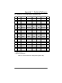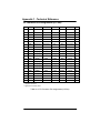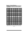
1
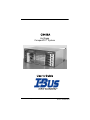
Hot Swap
CompactPCIâ System
C0406A Preliminary User’s Guide
Part No. 100575 Rev E
Doc No. 1000289 Rev 5
ECopyright 2000
All Rights Reserved
Part No. 100575 Rev E
Document No. 1000289 Rev 5
The information in this document is subject to change without prior notice in order to improve
reliability, design and function and does not represent commitment on the part of the manufacturer. In no event will the manufacturer be liable for direct, indirect, special, incidental, or consequential damages, or the possibility of such damages, arising out of the use of this information.
This document contains proprietary information protected by copyright. All rights are reserved.
No part of this manual may be reproduced by any mechanical, electronic, or other means in any
form without prior written permission of the manufacturer.
Trademarks
IBM PC is a registered trademark of International Business Machines Corporation. Intel and
Pentium are registered trademarks of Intel Corporation. Award is a registered trademark of
Award Software, Inc. Other product names mentioned herein are used for identification purposes only and may be trademarks and/or registered trademarks of their respective companies.
Customer Service
Worldwide Headquarter
I-Bus Corporation
2391 Zanker Road
#380
San Jose, CA 95131
United States
Phone : +1 (408) 428-6100
o
T l l rF e
: -78 7
7 -IBUS
Fax : +1 (408) 428-6101
Email : [email protected]
European Headquarter
I-Bus
Unit 6, Chichester Business Park
City Fields Way, Tangmere
West Sussex, P020 2LB, UK
Tel : +44 (0) 1243 756300
Local rate : 0845 450 4500
Fax : +44 (0) 1243 756301
Email : [email protected]
France & Italy
I-Bus
Les espaces de Sophia
80 route des Lucioles
06901 Sophia-Antipolis CEDEX
France
Tel : +33 (0)493 00 4360
Fax : +33 (0)493 00 4369
Email : [email protected]
Scandinavia
I-Bus
Drakegatan 10
BOX 184
401 23 Göteborg
Sweden
Tel: +46 (0)31-773 7117
Fax: +46 (0)31-773 7075
Email: [email protected]
C0406A User’s Guide
IBUS
C0406A User’s Guide
3
Dear Customer,
Thank you for purchasing an I-Bus Corporation product. We
hope that this product exceeds your expectations. It is our
desire to provide you with accurate, up-to-date information
about the product(s) you have purchased. We welcome
your comments and suggestions about our manuals.
You may email those comments and suggestions to
[email protected]. Please be sure to include your name,
the name of your company, the product you purchased, and
the manual number/revision (i.e. 00-00000-00 Rev. *). This
number is located on the title page.
At I-Bus Corporation, we value our customers and partners, and
you can continue to count on I-Bus Corporation to be customer
focused and to provide you a large range of solutions -- from
cost-effective to fully customized industrial computer
solutions.
Again, thank you for your committment to I-Bus Corporation.
We appreciate your business and look forward to continuing
to work with you and helping you reach your goals.
4
C0406A User’s Guide
Table of Contents
Chapter 1. Introduction
Introduction . . . . . . . . . . . . . . . . . . . . . . . . . . . . . . . . . . . . . . . . . . . . 1-1
Chapter 2. Specifications
2.1 Overview . . . . . . . . . . . . . . . . . . . . . . . . . . . . . . . . . . . . . . . . . . 2-1
2.2 Mechanical . . . . . . . . . . . . . . . . . . . . . . . . . . . . . . . . . . . . . . . . 2-3
2.2.1 Enclosure . . . . . . . . . . . . . . . . . . . . . . . . . . . . . . . . . . . . . . 2-3
2.2.1.1 Basic Chassis Configuration . . . . . . . . . . . . . . . . . . 2-3
2.2.1.2 Disk Drive Mounting . . . . . . . . . . . . . . . . . . . . . . . . . 2-4
2.3
Electrical . . . . . . . . . . . . . . . . . . . . . . . . . . . . . . . . . . . . . . . . 2-4
2.3.1 Power Subsystem . . . . . . . . . . . . . . . . . . . . . . . . . . . . . . . 2-4
2.3.1.1 Outputs (AC and DC) . . . . . . . . . . . . . . . . . . . . . . . . 2-4
2.3.2 Single Board Computer . . . . . . . . . . . . . . . . . . . . . . . . . . 2-5
2.3.3 CPCI Backplane . . . . . . . . . . . . . . . . . . . . . . . . . . . . . . . . 2-5
2.3.3.1 Monolithic Backplane . . . . . . . . . . . . . . . . . . . . . . . . 2-5
2.3.3.2 Media Bay Backplane . . . . . . . . . . . . . . . . . . . . . . . . 2-6
2.3.4 Alarm Module (Optional) . . . . . . . . . . . . . . . . . . . . . . . . . 2-7
2.4
Operating System Software . . . . . . . . . . . . . . . . . . . . . . . . 2-7
2.5
Environmental . . . . . . . . . . . . . . . . . . . . . . . . . . . . . . . . . . . . 2-7
2.5.1 Temperature . . . . . . . . . . . . . . . . . . . . . . . . . . . . . . . . . . . 2-7
2.5.2 Humidity . . . . . . . . . . . . . . . . . . . . . . . . . . . . . . . . . . . . . . . 2-8
2,5,3 Altitude . . . . . . . . . . . . . . . . . . . . . . . . . . . . . . . . . . . . . . . . 2-8
2.5.4 Vibration/Shock . . . . . . . . . . . . . . . . . . . . . . . . . . . . . . . . . 2-8
2.6
Safety Agency . . . . . . . . . . . . . . . . . . . . . . . . . . . . . . . . . . . . 2-8
Chapter 3. Hardware
3.1
SBC Module . . . . . . . . . . . . . . . . . . . . . . . . . . . . . . . . . . . . . 3-2
3.1.1 Removal and Installation of the SBC Board Module . . 3-2
3.2
Add-in Boards . . . . . . . . . . . . . . . . . . . . . . . . . . . . . . . . . . . . 3-4
3.2.1 Removal and Installation of Add-In Boards . . . . . . . . . . 3-4
C0406A User’s Guide
5
Table of Contents
3.3
Rear I/O Transition Modules . . . . . . . . . . . . . . . . . . . . . . . . 3-5
3.3.1 Removal and Installation of Rear I/O Modules . . . . . . . 3-5
3.4
SMC (System Management Controller) Board . . . . . . . . . 3-7
3.4.1 Indicators and Controls . . . . . . . . . . . . . . . . . . . . . . . . . . 3-7
3.4.1.1 Critical Alarm LED (CR) . . . . . . . . . . . . . . . . . . . . . . 3-7
3.4.1.2 Major Alarm LED (MJ) . . . . . . . . . . . . . . . . . . . . . . . 3-7
3.4.1.3 Minor Alarm LED (MN) . . . . . . . . . . . . . . . . . . . . . . . 3-7
3.4.1.4 Alarm Cut Off LED (ACO) . . . . . . . . . . . . . . . . . . . . 3-7
3.4.1.5 SMC Health (SMC) . . . . . . . . . . . . . . . . . . . . . . . . . . 3-7
3.4.1.6 Reset Pushbutton (RST) . . . . . . . . . . . . . . . . . . . . . 3-7
3.4.1.7 LED Test Pushbutton . . . . . . . . . . . . . . . . . . . . . . . . 3-8
3.4.1.8 ACO Off Pushbutton . . . . . . . . . . . . . . . . . . . . . . . . . 3-8
3.4.1.9 Battery Pushbutton (BAT) . . . . . . . . . . . . . . . . . . . . 3-8
3.4.2 Removal and Installation of the SMC Board . . . . . . . . 3-10
3.5
Backplane . . . . . . . . . . . . . . . . . . . . . . . . . . . . . . . . . . . . . . 3-10
3.5.1 Backplane Connector Pin Assignments . . . . . . . . . . . 3-10
3.5.2 Backplane Cooling Blower . . . . . . . . . . . . . . . . . . . . . . 3-11
3.5.2.1 Removal and Replacement of Backplane
Cooling Blower . . . . . . . . . . . . . . . . . . . . . . . . . . . . 3-11
Chapter 4. Power Distribution
4.1
Power Supply . . . . . . . . . . . . . . . . . . . . . . . . . . . . . . . . . . . . 4-1
4.1.1 Power Supply Alarm Cut-Off (P/S ACO) Switch . . . . . 4-2
4.1.2 Removing and Installing a Power Supply Module . . . . 4-2
Chapter 5. Drive Bay
5.1
Removing/Installing the Drives . . . . . . . . . . . . . . . . . . . . . . 5-1
5.1.1 To Replace a Hard Drive . . . . . . . . . . . . . . . . . . . . . . . . . 5-2
5.1.2 To Replace the Floppy or Tape Drive and/or CD ROM
Drive . . . . . . . . . . . . . . . . . . . . . . . . . . . . . . . . . . . . . . . . . 5-4
6
C0406A User’s Guide
Table of Contents
Chapter 6. Software
Software . . . . . . . . . . . . . . . . . . . . . . . . . . . . . . . . . . . . . . . . . . . . . . 6-1
Chapter 7. System Management Controller
Option
7.1
Overview . . . . . . . . . . . . . . . . . . . . . . . . . . . . . . . . . . . . . . . . 7-1
7.2
Description . . . . . . . . . . . . . . . . . . . . . . . . . . . . . . . . . . . . . . . 7-1
7.3
SMC BoardMechanical and Environmental
Specifications . . . . . . . . . . . . . . . . . . . . . . . . . . . . . . . . . . . . 7-3
7.3.1 Mechanical Specifications . . . . . . . . . . . . . . . . . . . . . . . . 7-3
7.3.1.1 Physical Size . . . . . . . . . . . . . . . . . . . . . . . . . . . . . . . 7-3
7.3.1.2 User Access . . . . . . . . . . . . . . . . . . . . . . . . . . . . . . . . 7-3
7.3.2 Environmental Specifications . . . . . . . . . . . . . . . . . . . . . 7-4
7.3.2.1 Temperature Range . . . . . . . . . . . . . . . . . . . . . . . . . 7-4
7.4
Sensors Supported . . . . . . . . . . . . . . . . . . . . . . . . . . . . . . . . 7-4
7.4.1 Temperature Sensors . . . . . . . . . . . . . . . . . . . . . . . . . . . 7-4
7.4.2 DC Voltages . . . . . . . . . . . . . . . . . . . . . . . . . . . . . . . . . . . 7-5
7.4.3 IPMB Power . . . . . . . . . . . . . . . . . . . . . . . . . . . . . . . . . . . . 7-5
7.4.4 Fan Tachometer . . . . . . . . . . . . . . . . . . . . . . . . . . . . . . . . 7-5
7.4.5 Power Supply Sensor . . . . . . . . . . . . . . . . . . . . . . . . . . . . 7-5
7.5
Electrical Description . . . . . . . . . . . . . . . . . . . . . . . . . . . . . . 7-6
7.5.1 Relay Contacts . . . . . . . . . . . . . . . . . . . . . . . . . . . . . . . . . 7-6
7.5.2 Battery Backup . . . . . . . . . . . . . . . . . . . . . . . . . . . . . . . . . 7-6
7.5.3 Host Serial Interface Ports . . . . . . . . . . . . . . . . . . . . . . . 7-7
7.5.4 Hot Pluggable Board . . . . . . . . . . . . . . . . . . . . . . . . . . . . 7-7
7.5.5 SMC Reset Switch . . . . . . . . . . . . . . . . . . . . . . . . . . . . . . 7-7
7.5.6 Digital Input/Output . . . . . . . . . . . . . . . . . . . . . . . . . . . . . . 7-7
7.5.7 ACO (Alarm Cut Off) . . . . . . . . . . . . . . . . . . . . . . . . . . . . 7-7
7.5.8 SMC Health LED . . . . . . . . . . . . . . . . . . . . . . . . . . . . . . . 7-8
7.5.9 LED Self-Test Pushbutton . . . . . . . . . . . . . . . . . . . . . . . . 7-8
C0406A User’s Guide
7
Table of Contents
7.5.10 Display/Status Board . . . . . . . . . . . . . . . . . . . . . . . . . . . 7-8
7.6
SMC Firmware Description . . . . . . . . . . . . . . . . . . . . . . . . . 7-8
7.6.1 General . . . . . . . . . . . . . . . . . . . . . . . . . . . . . . . . . . . . . . . 7-8
7.6.1.1 System Monitoring Software . . . . . . . . . . . . . . . . . . 7-9
7.6.1.2 IPMI Command Interface Software . . . . . . . . . . . 7-12
7.6.1.2.1 Packet Format . . . . . . . . . . . . . . . . . . . . . . . . . 7-12
7.6.1.2.2 Timeouts . . . . . . . . . . . . . . . . . . . . . . . . . . . . . . 7-12
7.6.1.3 Watchdog Timer . . . . . . . . . . . . . . . . . . . . . . . . . . . 7-13
7.7
SMC Connector Pins . . . . . . . . . . . . . . . . . . . . . . . . . . . . . 7-13
7.7.1 SMC-P3 Connector Pinout Assignments . . . . . . . . . . 7-13
7.7.2 SMC-P4 Connector Pinout Assignments . . . . . . . . . . 7-14
7.7.3 NEBS SMC Relay Output Connector Pinouts . . . . . . 7-15
7.7.4 RS-232 Pinouts . . . . . . . . . . . . . . . . . . . . . . . . . . . . . . . . 7-15
7.7.5 Battery Connector . . . . . . . . . . . . . . . . . . . . . . . . . . . . . . 7-16
7.7.6 Pin Assignments for DB9 Connector for
Digital Input/Output . . . . . . . . . . . . . . . . . . . . . . . . . . . . 7-16
Appendix 1. Technical Reference
P1 Connector Pin Assignments (System Slot) . . . . . . . . . . . . . A1-1
P1 Connector Pin Assignments (I/O Slot) . . . . . . . . . . . . . . . . . A1-2
P1 Signal Descriptions . . . . . . . . . . . . . . . . . . . . . . . . . . . . . . . . . A1-3
P2 Connector Pin Assignments (System Slot) . . . . . . . . . . . . . A1-5
P2 Connector Pin Assignments (I/O Slot) . . . . . . . . . . . . . . . . . A1-6
P2 Signal Descriptions . . . . . . . . . . . . . . . . . . . . . . . . . . . . . . . . . A1-7
P3, P4, P5 Connectors Pin Assignments (System Slot) . . . . . A1-7
P4 Connector Pin Assignments (Computer Telephony Bus)
(I/O Slot) . . . . . . . . . . . . . . . . . . . . . . . . . . . . . . . . . . . . . . . A1-8
P4 Signal Descriptions (Computer Telephony Bus) (I/O Slot) . A1-9
Appendix 2. Glossary of Terms
Appendix 3. Limited Warranty
Appendix 4. FCC Information
8
C0406A User’s Guide
Chapter 1 - Introduction
1 Introduction
Welcome to the I -Bus Corporation family of CompactPCIâ computer
systems. This manual provides information necessary to set up and
maintain your C0406A. The C0406A System is a CompactPCIâ platform
that may be equipped with either a SunSPARC or an Intel based single
board computer (SBC) module The system with an Intel based SBC
installed is designated CP0406A. The designation CS0406A refers to a
system with a SunSPARC SBC. In this manual, when referring to either
or both of these systems, the term C0406A will be used.
If 2-slot (8HP) SBC’s are used, such as the IBC 2600 or IBC 2601 in the
C0406A system, four expansion slots are available, while 1-slot (4HP)
SBC’s such as the CP1500 SunSPARC will allow for five expansion
slots.
The C0406A is intended to meet the need for a reduced height
rackmount CompactPCIâ system. The 4U high integrated enclosure
houses a six slot PICMG H.110 and PICMG 2.1 Hot Swap compliant
backplane. The enclosure can mount up to five 3.5” front accessible
SCSI SCA removable drives; it also mounts a front accessible CD ROM
drive and either a tape drive or a floppy drive. The enclosure supports
up to six 80MM depth rear I/O transition boards.
The C0406A has provision for the I-Bus Corporation Chassis
Management Controller (CMC). The CMC Board functions to
monitor and control the system environment of a custom cPCI
enclosure. It operates as an independent Chassis Management
Controller manageable through its RS232 port by an external
device. Refer to the CMC User’s Guide for further instructions
and specifications.
The system is equipped with a 300W (AC or DC) dual redundant power
supply.
C0406A User’s Guide
1-1
Chapter 1 - Introduction
This page was intentionally left blank
1-2
C0406A User’s Guide
Chapter 2 - Specifications
2 Specifications
2.1
Overview
GThe I-Bus C0406A system is a CompactPCI Platform intended
to serve the market for reduced height, rack mounted
environments.
GThe 4U high integrated enclosure houses a six slot PICMG
H.110 and PICMG 2.1, Hot Swap compliant backplane.
GThe enclosure can mount up to five 3.5” SCSI SCA drives, front
accessible/removable. The enclosure also mounts a front
accessible CD ROM drive and either a tape drive or a Floppy
Drive.
GThe system can be configured with either a SunSparc SBC or
an Intel SBC, with up to five peripheral cards.
GThe system supports up to six 80mm depth rear transition
boards. However, depending on which SBC occupies the
system slot, the top slot may or may not be available for a rear
I/O transition board. If the rear I/O board for the SBC is a
single slot board, the top slot is available for another I/O card.
If the SBC rear I/O board occupies two slots, the top slot will
not be availaable.
GThe system is equipped with a 300W (AC or DC) dual
redundant power supply.
GThe system can be optionally equipped with a Chassis
Management Controller (CMC) to monitor power supply status
and internal temperature. The CMC board occupies a special
rear slot above the rear I/0 transition slots, with status LEDs
visible on the chassis front panel. See Chapter 7 for
information on the SMC.
GFigures 2-1, 2-2, and 2-3 show the configuration for C0406A.
C0406A User’s Guide
2-1
Chapter 2 - Specifications
POWER
1
2
ACO TEST
3
CR MJ MN
4
5
6
Figure 2-1. C0406A System Configuration - Front View
Figure 2-2. C0406A System Configuration - Rear View
2-2
C0406A User’s Guide
Chapter 2 - Specifications
Figure 2-3. C0406A System Configuration - Top View
2.2
Mechanical
2.2.1
Enclosure
GDesigned for EIA RS-310 19”and 23” rack mounts
GDetachable rack mount brackets can be positioned for front
flush mount or mid-chassis rack mount
GA single rack mount bracket design is used for both 19” and 23”
racks, both left and right sides, incorporating mounting
keyways for temporary hanging of the chassis.
GEnclosure front panel incorporates a DC on-off switch, plus an
LED power-on indicator.
GMain power input is in the rear of the enclosure.
2.2.1.1
Basic Chassis Configuration
GEurocard 6U card cage, per PICMG 2.0 Rev 3.0, CompactPCI
specification.
GSpace for a total of six 4 HP slots, oriented horizontally (total
opening of 4.80” front and rear).
C0406A User’s Guide
2-3
Chapter 2 - Specifications
GTotal rack height is 4U (7.00”)
GCool air intake is in front; hot air exhaust is in the rear.
GOverall dimensions are 7.00” High, 17.00” Wide, 15.25” deep.
2.2.1.2
Disk Drive Mounting
GMounts five 3.5” SCSI SCA hard disk drives, horizontally.
These disk drives are front accessible/ removable.
GA CD ROM drive and Floppy Drive, oriented horizontally, mount
above the backplane. Both are accessible through the front
panel.
2.3
Electrical
2.3.1
Power Subsystem
GDual redundant power supplies, delivering 300W output from
AC or DC mains input.
GAC input range: 90-264VAC, 47-63Hz, auto sensing, auto
ranging.
GDC input range: -36 to –72VDC.
2.3.1.1
Outputs (AC and DC)
GMaximum loads: +5VDC @ 25A +3.3VDC @ 20A +12VDC
@ 10A -12VDC @ 1A; combined total output not to exceed
300W; combined total output of +5V and +3.3V not to exceed
150W.
GMinimum loads: +5VDC @ 3A +3.3VDC @ 0.5A +12VDC @
1A
Ripple (max): 50mV for +5V and 3.3V, 100mV for +12V and
–12V.
GLoad regulation: ±5% for +5V and +3.3V, ±10% for +12VDC
and, -12VDC
GLine regulation: ±0.5% for all outputs.
GRipple: 50mV for +5V and 3.3V, 100mV for +12V, 150mV for
–12V
GMTBF: 100,000 hrs, full load at 25°C (MIL-217).
GOperating temperature Range: 0°C to 50°C
2-4
C0406A User’s Guide
Chapter 2 - Specifications
2.3.2
Single Board Computer
GThe system currently supports the following I-Bus/Phoenix
Single Board Computers and corresponding rear I/O transition
modules:
CS0406A
SUN - CP1500/2060/2040/2080 SPARC engines
360, 460, or 500MHz CPU
Standard 512MB Up to 2GB RAM supported.
CP0406A
I-Bus/Phoenix IBC2600 or IBC2601 SBCs
600, 700 or 850 MHz Intel PIII CPU
433 MHz or 566 MHz Celeron CPU
128, 256, 512, or 768 MB RAM
2.3.3
CPCI Backplane
2.3.3.1
Monolithic Backplane
GThis backplane contains two ATX connectors for DC power
input.
GThe backplane supports a maximum of 400 watts input power,
however, utilizing this capability will require that the power
supplies no longer be hot-swap redundant.
GThe back plane has one cPCI system Slot and five cPCI
I/O slots. There is also an additional slot in the rear for the
SMC board (see Chapter 7 for instructions on the SMC option).
GThe CompactPCI system slot has a PCI bus with 32-bit/64-bit
at 33MHz.
G All CompactPCI I/O slots have PCI bus with 32-bit/64-bit at
33MHz and H.110 bus.
GThe back plane complies with the following specifications:
CompactPCI Specification: PICMG 2.0 R3.0
Hot Swap Specification: PICMG 2.1 R2.0
System Management Specification: PICMG 2.9 R1.0
CompactPCI Computer Telephony: PICMG 2.5 R1.0
GBackplane Dimension: 11.2 X 4.7 inches.
GTemperature Range
Operation: -5_C to 55_C
Storage: -40_C to 85_C
C0406A User’s Guide
2-5
Chapter 2 - Specifications
2.3.3.2
Media Bay Backplane
GThe chassis incorporates five Media Bay Backplanes. Each
backplane contains one 4-pin power connector, one 68-pin
SCSI connector, one 80-pin SCA connector, and one 18-pin
HD Select connector
GIndividual Media Bay Backplanes are 0.905 wide by 3.937 high.
GA single internal SCSI cable goes from the rear SCSI connector
above the SMC slot to each of the media bay backplanes, to
the CD ROM drive, to the tape drive, and back to the SCSI
Termination connector above the SMC slot.
Connect an active SCSI terminator to the SCSI Termination
connector. Connect an shielded SCSI cable between the SCSI
Controller and the connector labeled “SCSI” on the rear of the
chassis. Note that the 18” shielded SCSI cable and the SCSI
terminator are shipped separately as accessories, not attached
to the unit. Figure 2-4 shows how these are to be connected.
Figure 2-4. Connecting SCSI Cable and Terminator
G Power to the Media Bay backplane is supplied through a
standard PC peripheral power connector.
G Figure 2-5 shows the Media Bay Backplane connectors and
layout.
2-6
C0406A User’s Guide
Chapter 2 - Specifications
REAR VIEW
SIDE VIEW
Figure 2-5. Connectors on Media Bay Backplane
2.3.4
Alarm Module (Optional)
See Chapter 7 for functionality
2.4
Operating System Software
Configuration
Software
CS0406A
Solaris 2.6, 7 or 8
CP0406A
Windows NT, 98, 2000 or Linux Redhat 7.0
2.5
Environmental
2.5.1
Temperature
GContinuous Operating: 0oC to 40oC
GShort-term (30 mins max) Operating: –5oC to 55oC
GNon-operating: –40oC to 70oC
C0406A User’s Guide
2-7
Chapter 2 - Specifications
2.5.2
Humidity
GOperating: 5-85% @ 40oC (non-condensing).
GNon-operating: 0-95% @ 40oC (non-condensing).
2.5.3
Altitude
GOperating altitude 6000 ft. at operating temperature, 15,000 ft.
at 25oC.
GNon-operating altitude 40,000 ft.
2.5.4
Vibration/Shock
GOperating vibration: 0.25g @ 2-100 Hz, 1.5g @ 100-500 Hz.
GStorage/transport vibration: 2g @ 5-500 Hz.
GOperating shock: 10g @ 11 msec
GStorage/transport shock: 30g @ 11 msec.
2.6
Safety Agency
GUL 1950, Recognized Component.
GcUL or CSA 950 Approved.
GTUV EN 60950 Certified.
GCE Certified.
GFCC Class A.
2-8
C0406A User’s Guide
Chapter 3 - Hardware
3 Hardware
This chapter discusses the removal and installation of the Single Board
Computer (SBC) module, add-in board modules, rear I/O modules, SMC
Board, backplane, and cooling blower.
CAUTION!
Unless working on hot-swap components, always shut down the
system and turn OFF all power and disconnect the power cord
before working on the system.
CAUTION!
Connector pins on CompactPCIâ backplanes are extremely
delicate and can easily be bent. Precise alignment and proper
insertion/ejection procedures are critical in order to avoid
bending backplane pins.
CAUTION!
Electrostatic Discharge (ESD) may damage memory chips,
programmed devices and other electrical components. ESD can
be prevented by wearing a wrist strap attached to a ground post on
a static mat. Handling of this product should ONLY be done by a
properly trained technician in an approved ESD work area.
CAUTION! PLEASE NOTE
Any Unoccupied slots, both front and rear, must be
covered by a filler plate in order for proper cooling air
flow to take place. Leaving a slot uncovered could
result in overheating and failure of one or more system
components
C0406A User’s Guide
3-1
Chapter 3 - Hardware
3.1
SBC Module
In the C0406A, the SBC module is mounted in the second slot from the
top. The C0406A supports either a SunSPARC CP1500 or an Intel
based SBC Module such as the I-Bus/Phoenix IBC 2600 or IBC 2601.
The SBC module is mounted through the front of the enclosure. It is
held in place with two injector/ejector handles that stabilize the board
when they are engaged. It is also secured by two captive screws located
on the SBC module’s faceplate. See the following instructions if the SBC
module needs to be removed for maintenance or replacement
3.1.1
Removal and Installation of the SBC Board Module
1 Shut down the system and turn off the DC power via the switch on
the front of the chassis. Verify that the Power On light is
extinguished.
2 Loosen the two captive screws on the SBC module’s faceplate.
Note: When loosened, the screws should be pushed inward to
prevent obstructing the movement of the injector/ejector handles.
3 Completely retract the injector/ejector handles by pressing them
away from each other.
Note: Some force may be required.
4 Slide the SBC module out of the chassis.
5 With the Injector/Ejector handles in their outward (open) position,
insert the SBC module on its card guides until the handle latches
begin to engage. Make sure the two guide pins mate properly into
the corresponding hole in the SBC card guides.
6 Fully seat the SBC module by engaging the injector/ejector
handles, pressing them to their full inward position.
Note: If a firm steady pressure on the handles does not readily
seat the board, verify proper board alignment, clear insertion path
and connector pin straightness.
7 Secure the SBC board module by tightening the two captive
screws.
3-2
C0406A User’s Guide
Chapter 3 - Hardware
Figure 3-1: I-Bus IBC 2600 SBC Board
Figure 3-2: SunSPARC Ultra IIi SBC Board
C0406A User’s Guide
3-3
Chapter 3 - Hardware
3.2
Add-in boards
All add-in board modules are mounted through the front of the enclosure.
They are held in place with two injector/ejector handles that stabilize the
boards when they are engaged.
The C0406A provides for full hot swap of add-in boards to PICMG 2.1
R2.0 and PICMG 2.12 R1.0 standards, supporting Pigeon Point Systems
Hot Swap Kit software. For full I/O Board hot swap, the system must be
running Pigeon Point software under one of the following systems:
a) Microsoft Windows 2000 (Advanced Server, Server,
Professional)
b) Microsoft Windows NT with a Hot Swap Manager
3.2.1
Removal and Installation of Add-In Boards
1 (Hot swap only) Toggle the bottom injector/ejector handle of the
card down or activate the hot swap thumb switch.
(Non-Hot swap only) Shut down the system and turn off the main
system power.
2 (Hot swap only) The card’s blue LED should light, indicating that
the card is safe to remove.
3 Loosen the screws on the add-in board’s faceplate, if any.
4 Completely retract the injector/ejector handles of the add-in board
module by pressing them away from each other.
Note: Some force may be required.
5 Slide the add-in board module out of the chassis.
Note: If you do not plan on immediately replacing a removed add-in
board, you must close the space left open with a filler panel in
order to maintain EMI specifications.
To insert or re-insert a card back into that slot, the following must be
done.
1 With the Injector/Ejector handles in their outward (open) position,
insert the add-in board module on its card guides until the handle
latches begin to engage. Make sure the two guide pins mate
properly into the corresponding hole in the add-in board card
guides.
2 Engage the injector/ejector handles by pressing them towards
each other.
Note: If a firm steady pressure on the handles does not readily seat the
board, verify proper board alignment, clear insertion path and
connector pin straightness.
3-4
C0406A User’s Guide
Chapter 3 - Hardware
3 (Hot swap only) The blue LED will light momentarily and should
extinguish after full insertion is complete.
4 The operating system should automatically recognize the card and
accomplish the correct steps to allocate resources and load
drivers.
5 Secure the add-in board module by tightening the two captive
screws (if they are present).
For hot swap instructions on other third party hot swap software,
consult the applicable instruction manual for the software.
3.3
Rear I/O Transition Modules
The C0406A is configured to support rear I/O transition modules. As an
optional feature, the IBC 2700, the IBC 2702, or the SunSPARC CP1500
rear transition module may be installed.
NOTE, however, that the Intel based IBC 2700 rear I/O transition module
occupies two slot spaces. The SunSPARC CP1500 rear I/O transition
module occupies only one space, but because of the space required for
cabling, the slot above is not available for other transition modules, and
must be covered with a filler panel. Therefore, depending on which SBC
occupies the system slot, the top slot may or may not be available for a
rear I/O transition board.
3.3.1
Removal and Installation of the Rear I/O Modules
1 Shut down the system and turn off the main system power.
2 Loosen the screws on the rear I/O board’s faceplate, if any.
3 Completely retract the injector/ejector handles of the rear I/O
board module by pressing them away from each other.
Note: Some force may be required.
4 Slide the rear I/O board module out of the chassis.
Note: If you do not plan on immediately replacing a removed rear I/O
board, you must close the space left open with a filler panel in
order to maintain EMI specifications.
To insert or re-insert a card back into that slot, the following must be
done.
1 With the Injector/Ejector handles in their outward (open) position,
insert the rear I/O module on its card guides until the handle
latches begin to engage. Make sure the two guide pins mate
properly into the corresponding hole in the rear I/O card guides.
C0406A User’s Guide
3-5
Chapter 3 - Hardware
2 Engage the injector/ejector handles by pressing them towards
each other.
Note: If a firm steady pressure on the handles does not readily seat the
board, verify proper board alignment, clear insertion path and
connector pin straightness.
3 Secure the rear I/O board module by tightening the two captive
screws (if they are present).
IBC 2700
SunSPARC
Figure 3-3: Rear I/O Transition Modules
3-6
C0406A User’s Guide
Chapter 3 - Hardware
3.4
CMC (Chassis Management Controller) Board
The C0406A supports a Chassis Management Controller (CMC) Board in
top rear slot of the backplane. Refer to Chapter 7 for more information
about this optional feature.
3.4.1
Indicators and Controls
Figure 3-4 is a drawing of the front plate of the SCMC Board. LED
indicators and pushbutton controls on the board are as follows:
3.4.1.1
Critical Alarm LED (CR)
This Red LED, when illuminated, indicates the presence of a Critical
Alarm condition.
3.4.1.2
Major Alarm LED (MJ)
This Orange LED, when illuminated, indicates the presence of a Major
Alarm condition.
3.4.1.3
Minor Alarm LED (MN)
This Yellow LED, when illuminated, indicates the presence of a Minor
Alarm condition.
3.4.1.4
Alarm Cut Off LED (ACO)
This Yellow LED, when illuminated, indicates that the audible alarm,
which sounds upon the occurence of an alarm condition, has been
silenced by the ACO OFF pushbutton. Should another alarm condition
occur while the previous alarm condition is still present, the LED will be
extinguished and the audible alarm will again sound.
3.4.1.5
SMC Health LED (CMC)
Normally, this LED is illuminated Green. Should any software or
hardware malfunction cause the CMC Board to become inoperative, this
LED will turn Red. It will also turn Red temporarily during a reset of the
SMC processor initiated by the RST pushbutton.
3.4.1.6
Reset Pushbutton (RST)
This pushbutton restarts the processor on the CMC Board. There is little
reason to use it in normal operation unless the user is doing software
development.
C0406A User’s Guide
3-7
Chapter 3 - Hardware
3.4.1.7
LED Test Pushbutton
This pushbutton initiates a test cycle of the five LEDs on the front plate
of the CMC Board. Each LED, beginning with the Critical Alarm LED, will
be illuminated for approximately one second. The last LED, the CMC
Helath LED, will turn Red for approximately one second before reverting
to its normal Green condition.
3.4.1.8
ACO Off Pushbutton
This pushbutton silences the audible alarm that sounds upon the
occurrence of any alarm condition and also illuminates the ACO LED.
Silencing the audible alarm does not correct the alarm condition. Also,
the occurrence of a subsequent additional alarm condition will reactivate
the audible alarm.
3.4.1.9
Battery Pushbutton (BAT)
This pushbutton is employed to prevent draining of the CMC Board
backup battery after an intentional system shutdown. When the main
system power is shut down, the CMC Board will remain operative, being
powered by its backup battery. Pressing the BAT pushbutton at this time
will disconnect the battery and de-energize the CMC Board.
3-8
C0406A User’s Guide
Chapter 3 - Hardware
Figure 3-4. CMC Board Front Plate
C0406A User’s Guide
3-9
Chapter 3 - Hardware
3.4.2
Removal and Installation of the CMC Board
1 Shut down the system and turn off the main system power.
2 Loosen the screws on the CMC board’s faceplate, if any.
3 Completely retract the injector/ejector handles of the rear I/O
board module by pressing them away from each other.
Note: Some force may be required.
4 Slide the CMC board module out of the chassis.
Note: If you do not plan on immediately replacing a removed SCMC
board, you must close the space left open with a filler panel in
order to maintain EMI specifications.
Note: To prevent draining the backup battery on the CMC board after an
intentional system shutdown, press the BAT pushbutton on the
front plate of the CMC Board. Battery backup will be re-initialized
at the next system start-up.
To insert or re-insert an CMC Board back into that slot, the following
must be done.
1 With the Injector/Ejector handles in their outward (open) position,
insert the rear I/O module on its card guides until the handle
latches begin to engage. Make sure the two guide pins mate
properly into the corresponding hole in the rear I/O card guides.
2 Engage the injector/ejector handles by pressing them towards
each other.
Note: If a firm steady pressure on the handles does not readily seat the
board, verify proper board alignment, clear insertion path and
connector pin straightness.
3 Secure the rear I/O board module by tightening the two captive
screws (if they are present).
3.5
Backplane
3.5.1
Backplane Connector Pin Assignments
The C0406A supports a 6-slot CompactPCIâ backplane. See
Appendix 1, Tables A1-1 thru A1-5 for connector information for the
CompactPCIâ backplane.
Do not attempt to remove the backplane from the chassis. The
backplane is not a user serviceable item. Please contact I -Bus
Technical Support for further information.
3-10
C0406A User’s Guide
Chapter 3 - Hardware
3.5.2
Backplane Cooling Blower
The C0406A features a hot-swap backplane cooling blower. It is located
to the left of the backplane card cage behnd the SMC Alarm Status
Display Panel (see Figure 3-5).
3.5.2.1
Removal and Replacement of Backplane Cooling
Blower.
The backplane cooling blower can be removed without shutting down the
system by simply loosening the captive thumb screw and withdrawing
the blower. Then insert the replacement blower and tighten the thumb
screw. Always replace the blower immediately after removing it to avoid
system overheating.
Figure 3-5. Cooling Blower (Partially Withdrawn)
C0406A User’s Guide
3-11
Chapter 3 - Hardware
This page was intentionally left blank
3-12
C0406A User’s Guide
Chapter 4 - Power Distribution
4 Power Distribution
This chapter discusses the power supply and provides installation and
removal instructions.
CAUTION!
Equipment uses multiple power cords. Unless working with
hot-swap components, always shut down the system, turn OFF
all power, and disconnect all power cords before working on
the system.
Power supply replacement is to be done by qualified service
personnel only.
4.1
Power Supply
Chassis DC power is provided by dual redundant power supplies with a
combined maximum total output of 300W from AC or DC input. In this
optional arrangement, either power supply may be hot swapped without
interrupting system operation.
Figure 4-1 shows the dual redundant power supplies with one partially
withdrawn.
Figure 4-1. Dual Redundant Power Supplies
(One Shown Partially Withdrawn)
C0406A User’s Guide
4-1
Chapter 4 - Power Distribution
4.1.1
Power Supply Alarm Cut-Off (P/S ACO) Switch
If one of the power supplies should fail, an audible alarm will sound. This
audible signal can be silenced by pressing the P/S ACO switch (a red
button on the rear of the chassis; see Figure 4-1). Please note that
silencing the audible alarm does not correct the failed condition of the
power supply.
If the system is equipped with the SMC Option (See Chapter 7), the red
P/S ACO switch will not be present, and the failure of any power supply
will be indicated by an SMC major alarm and the SMC Board ACO
pushbutton will function to silence the audible alarm.
4.1.2
Removing and Installing a Power Supply Module
In normal operation the two power supplies share the load equally, but
either one is capable of sustaining the entire 300 watts of load, should
the other one fail. To replace a failed power supply, follow the steps
below:
1 Determine which power supply has failed by observing which one has
its green LED not illuminated.
2 Turn off the power switch on the rear face of the failed power supply.
3 Disconnect the power cord/cable from the power supply to be
replaced.
4 Press down on the release latch, grasp the power supply handle and
withdraw it from its housing.
5 Verify that the power switch on the replacement power supply is in
the off position.
6 Insert the new replacement power supply and, holding down its
release latch, press it firmly into place.
7 Reconnect the power cord/cable to the replacement power supply.
8 Turn on the power supply switch and note that the green LED
becomes illuminated.
4-2
C0406A User’s Guide
Chapter 5 - Drive Bay
5 Drive Bay
This chapter describes the removal and installation of the drives.
CAUTION!
Unless working on hot-swap components, always shut down
the system and turn OFF all power and disconnect the power
cord before working on the system.
CAUTION!
Electrostatic Discharge (ESD) may damage memory chips,
programmed devices and other electrical components. ESD can
be prevented by wearing a wrist strap attached to a ground post on
a static mat. Handling of this product should ONLY be done by a
properly trained technician in an approved ESD work area.
5.1
Removing/Installing the Drives
The C0406A provides for up to five SCA swappable hard drives. They
may be either “hot-swap” or “cold-swap,” depending on your system
configuration. The cold-swap configuration requires that power to the
system be shut down before withdrawing the drive. The drives are
mounted in shuttles to allow easy withdrawal and replacement.
Figure 5-1 shows a hard drive shuttle partially withdrawn.
Figure 5-1. Hard Drive Shuttle Partially Withdrawn
C0406A User’s Guide
5-1
Chapter 5 - Drive Bay
5.1.1
To Replace a Hard Drive
1 If your system configuration requires that the drive be
“cold-swapped,” shut down the system and turn off power to the
hard drive(s).
2 Insert a suitable tool in the small hole in the front of the shuttle to
release the shuttle handle. A “Combi-Tool” is shipped with each
C0406A unit, and one end of this tool is intended to be used to
release the shuttle handle. If this tool is not available, a stiff wire
such as a straighened out paper clip or any similar device will
work well.
3 Using the handle just released, withdraw the shuttle from the
chassis.
4 If the replacement drive is already mounted in a shuttle, skip to
Step 11. If not, proceed with the following steps.
5 Place the drive shuttle on an ESD safe work surface and observe
proper ESD precautions as you perform the following steps.
6 Remove the four screws, two from each side and remove the drive
from the shuttle.
7 Position the replacement drive in the shuttle. Be sure the shuttle
is oriented as shown in Figure 5-2 and the replacement drive has
its component side down.
8 Replace the four screws removed in Step 6 Be sure the screws
are inserted in the two slotted holes in the shuttle.
9 Before tightening the screws, slide the drive forward or back so
that the holes in the drive align with the non-slotted holes in the
shuttle. Then tighten the screws.
10 Turn the shuttle over and connect the leads for the drive activity
LED to the correct jumper position on the drive (see Figure 5-3).
The correct jumper for LED Out should be identified by a marking
or label on the drive (as shown in Figure 5-3). Note that the
connection is polarity sensitive.
11 Insert the shuttle with the replacement drive into the C0406A
chassis and close the shuttle handle to lock it into position.
If you are unable to close the shuttle handle into its locked
position, it may be necessary to remove the drive and loosen the
four screws holding it to the shuttle, and slide the drive forward
slightly. Then tighten the screws. This should allow the drive to
be fully inserted into its slot in the chassis.
5-2
C0406A User’s Guide
Chapter 5 - Drive Bay
Figure 5-2: Hard Drive Shuttle
Figure 5-3: Hard Drive Mounted in Shuttle
C0406A User’s Guide
5-3
Chapter 5 - Drive Bay
5.1.2
To Replace the Floppy or Tape Drive and/or
CD-ROM Drive
The C0406A provides one 5.25” CD-ROM drive and either one 3.5”
floppy drive or one 3.5” tape drive located above the card cage. To
replace either of these drives follow the steps below:
1 Shut down the system and turn off the main system power.
2 Disconnect the power cord from the power supplies at the rear of
the unit.
3 Remove the unit from the rack and place it on an ESD safe work
surface.
4 Remove the top cover.
5 Disconnect the power and data cables from the floppy or tape
drive and the CD-ROM drive.
6 Remove the C0406A front panel bezel. There are three screws
on the top surface, two on each end, and two on the bottom that
hold this part in place. Figure 5-4 shows this bezel removed and
swung aside.
Figure 5-4. C0406A with Front Panel Bezel Removed
7 Remove any hard drives that are in the Hard Drive Bay.
8 Using a short Phillips screw driver, remove the screws shown in
Figures 5-5, 5-6, and 5-7.
5-4
C0406A User’s Guide
Chapter 5 - Drive Bay
Figure 5-5. Removing the Drive Mounting Plate
Figure 5-6. Removing the Drive Mounting Plate
C0406A User’s Guide
5-5
Chapter 5 - Drive Bay
Figure 5-7. Removing the Drive Mounting Plate
9 Lift the right hand end of the drive mounting plate and draw it forward
out of the chassis. You may now turn the plate over and remove the
screws that hold the drive to be replaced to the plate.
10 After replacing the drive, reassemble the unit by reversing the above
steps.
5-6
C0406A User’s Guide
Chapter 6 - Software
6 Software
The C0406 can be preloaded with Red Hat Linux, Microsoft Windows
2000 or Windows NT 4.0 or Sun Solaris 2.6, 7, or 8 Operating System.
For software configuration support on this platform, refer to the software
manufacturer’s Installation and Configuration manual.
For Pigeon Point (or other third party) Hot Swap Kit software, refer to the
appropriate User’s Manual.
C0406A User’s Guide
6-1
Chapter 6 - Software
This page was intentionally left blank
6-2
C0406A User’s Guide
Chapter 7 - System Management Controller Option
7 Chassis Management Controller Option
7.1
Overview
This chapter describes the functional and interface specifications
of the I-Bus Chassis Management Controller (CMC). The
CMC Board functions to monitor and control the system
environment of a custom cPCI enclosure. It operates as an
independent Chassis Management Controller manageable
through its RS232 port by an external device. It conforms to the
PICMG 2.9 R1.0 System Management Specification, supporting
the following:
IPMB0 on the cPCI backplane
IPMI Command Protocol
Local I2C bus to connect temperature sensors and any
other remote sensing devices
The IPMB0 is driven by an I2C bus controller.
7.2
Description
The SCMC Board is plugged into the back of an I -Bus cPCI
monolithic backplane, and mounted vertically behind the power supply
connectors. Figure 7-1 shows the architecture of an CMC Board in
conjunction with the SBC(s) in a cPCI system.
The CMC board has two I@C ports, to support cPCI System Management
Bus per PICMG 2.9. One of the ports is used as the local I@C bus to be
connected to temperature sensors, etc. The other port is used as the
IPMB0 bus and routed to the cPCI backplane connectors.
Control and communication with the CMC board is via IPMI -command
structure through the RS232 port(s). For example, the host controller is
capable of changing and setting limits/masks for the sensors via the
IPMI command.
The CMC board is capable of replying to messages from the host
controller.
C0406A User’s Guide
7-1
Chapter 7 - System Management Controller Option
Figure 7-1. Block Diagram of a Chassis Management
Controller
7-2
C0406A User’s Guide
Chapter 7 - Chassis Management Controller Option
Figure 7-2 shows the I2C ports assignment between the CMC controller
chip (e.g., VSC215) and the CompactPCI backplane.
Figure 7-2. PC Ports Assignment
7.3
CMC Board Mechanical and Environmental
Specifications
7.3.1
Mechanical Specifications
7.3.1.1
Physical Size
G9.190” high X 3.150” wide.
GMounts to 6U rear panel of I-Bus custom monolithic cPCI
backplane.
7.3.1.2
User Access
GChasis Management Controller Card is mounted at the top of
the backplane in the rear of the chassis, above the rear I/O
card cage with the CMC LEDs on the right side.
GShielded, EMI -filtered type connectors for Chassis Management
Controller
GRelays and RS-232 interface directly accessible externally
through cutouts in rear 6U panel.
C0406A User’s Guide
7-3
Chapter 7 - Chassis Management Controller Option
GAdditional headers on the CMC board are available to connect
RS232 devices (such as host SBCs) directly to the board.
7.3.2
7.3.2.1
Environmental Specifications
Temperature Range
GOperation: 0_C to 55_C.
GStorage: -40_C to 85_C.
7.4
Sensors Supported
The SCMC board is capable of reading temperatures, DC voltages, Fan
Tachometers, as well as controlling speed of the fans, and outputting
alarm condition on the relay outputs and LEDs.
7.4.1
Temperature Sensors
There are connector(s) in the backplane to extend the Local I@C bus
(I2C3_CLK and I2C3_SDA) to the external temperature sensor modules
(LM75s). The LM75s will be on I@C bus 3 of the VSC215 and then tied to
I2C3_CLK and I2C3_SDA on the SMC connector (see figure 7-2).
The SCMC supports up to eight temperature sensors.
Temperature sensor 0 (intake) is located on the air intake side of the
card cage near the system slot about halfway between the front of the
chassis and the backplane. Temperature sensor 7 (exhaust) is located
in the air exhaust path behind the blower. Sensors 1 through 6 are not
used.
The range and accuracy for the temperature readings is shown in the
following table:
Temperature
0ºC to 70ºC
Sensor Number
LM75 – 0
LM75 – 1
LM75 – 2
LM75 – 3
LM75 – 4
LM75 – 5
LM75 – 6
LM75 – 7
7-4
Range
-55ºC to 125ºC
Resolution (8 bit)
1.0ºC
I@C Address
0x90
0x92
0x94
0x96
0x98
0x9A
0x9C
0x9E
C0406A User’s Guide
Chapter 7 - Chassis Management Controller Option
7.4.2
DC Voltages
The CMC is capable of reading and monitoring the following DC
voltages: +12V, -12V, +5V, +3.3V, Battery Output. By default, voltage
sensors will trigger major alarms when their threshold limits are
exceeded.
The ranges and accuracy for the above voltages is shown in the
following table:
Voltage
+3.3V
+5V
Range
+3.10 to +3.5V
+4.75 to +5.25V
Resolution (10 bit)
5 mV
10 mV
+12V
--12V
+11.40 to +12.60V
--11.40 to --12.60V
15 mV
15 mV
Battery 6V +5.50 to +6.50V
7.4.3
10 mV
IPMB Power
The +5V DC IPMB Power on the bus is regulated separately from the
rest of the SMC circuit. It is taken from +12 Vdc input and regulated
down to +5 Vdc. Optional battery backup is provided.
The IPMB Power is capable of supplying 1 ampere DC current at +5 Vdc
per PICMG 2.9.
Voltage Tolerance: +5V ±3% at backplane, 0A to 0.8A load.
Voltage Tolerance: +5V ±3% at backplane, with 500 mA hot swap
transient.
The CMC board monitors its own IPMB power voltage.
Any IPMB_PWR voltage reading outside the above thresholds will set a
Major Alarm.
7.4.4
Fan Tachometer
The fan tachometer monitors the speed of the cooling blower. Refer to
Table 7-1 Default SDR Parameters on page 7-11 for fan speed
thresholds.
7.4.5
Power Supply Sensor
The power supply sensor detects the health of the power supply
subsystem. If the subsystem is good, the sensor will read 0. A reading
of 1 indicates that the power supply subsystem is not healthy. By
default, this will cause a major alarm.
C0406A User’s Guide
7-5
Chapter 7 - Chassis Management Controller Option
7.5
Electrical Description
7.5.1
Relay Contacts
There are three NEBS Alarm Relays for the following alarm conditions:
Critical Alarm (red LED on).
Major Alarm (orange LED on).
Minor Alarm (yellow LED on).
The Alarm Relays are accessible on the board through a DB15
connector. All alarm relays are of the type: SPDT, HAMLIN,
HE721C0500.
Leads for each relay: NC, NO, Common, and 1 Kilo-ohm Resistor
Common.
7.5.2
Battery Backup
The CMC board provides a battery charger for charging an on-board 6V
sealed rechargable battery.
The SCMC Board generates IPMB_PWR when powered by battery
backup.
The SCMC Board will continue to operate when powered by battery
backup.
The SCMC Board provides a connector to an external 6V battery.
The recommended battery is POWERSONIC PS-605, with battery
capacity of 0.5 Ah.
The output range of Battery Voltage is +5.75V to +6.35V.
The SCMC board monitors the battery output voltage.
Any battery voltage reading outside the above threshold will set an
Alarm.
Please Note:
To prevent draining the backup battery on the CMC board
after an intentional system shutdown, press the BAT
pushbutton on the front plate of the CMC Board. Battery
backup will be re-initialized at the next system start-up.
7-6
C0406A User’s Guide
Chapter 7 - Chassis Management Controller Option
7.5.3
Host Serial Interface Ports
The CMC board provides two RS232 serial ports to connect to the host
SBC(s). Connection is made through DB9 style connectors and headers
on the board.
The default port setup is 19200, 8, n, 1.
7.5.4
Hot Pluggable Board
The CMC board is hot -pluggable, that is, it will not require the chassis
power supply to be turned off to insert and remove the board.
Furthermore, the insertion and removal of the CMC board will not cause
system interruption or system reset.
7.5.5
CMC Reset Switch
There is a pushbutton reset on the CMC board to reset the SCMC
microcontroller momentarily.
There is an opening to allow pressing of the pushbutton from the outside.
7.5.6
Digital Input/Output
The CMC Board provides three TTL Level Inputs and three TTL Level
Outputs, accessible on a DB9 connector.
7.5.7
ACO (Alarm Cut Off)
The CMC board provides an external pushbutton input to allow the
software to disable the active audible alarm.
The ACO pushbutton operates as a toggle switch, allowing enable and
disable of the ACO state by pressing the pushbutton repeatedly. The
current ACO state is reflected in the ACO LED.
Activating the ACO (by pressing the pushbutton) when any of the alarm
conditions occurs, will turn off the on-board audible piezo buzzer. This
does not affect the actual alarm condition.
C0406A User’s Guide
7-7
Chapter 7 - Chassis Management Controller Option
When a new change in the alarm condition occurs, the enabled ACO will
be overridden. In other words, the audible alarm will be reenabled
automatically until the ACO push button is pressed again.
7.5.8
CMC Health LED
The CMC board firmware changes the color of the CMC LED from red to
green when it finishes a self-test and begins operating normally. Any
conditions that prevent the CMC firmware from running normally will
cause this LED to turn red.
7.5.9
LED Self-Test Pushbutton
The CMC board provides an external Pushbutton for self -test of
display/status LEDs. Activating the LED Self-Test Pushbutton at any
time will cause the display/status LEDs to be turned on individually for
one second, one LED at a time. The sequence is: CRITICAL, MAJOR,
MINOR, ACO, and SMC LEDs.
7.5.10
Display/Status Board
The SCMC board is able to control an external LED display/status board
to display the alarm status of the system. The display/status signals are
provided via the backplane. The following signals are on the
CompactPCI connector for the CMC:
CRITICAL LED (red)
MAJOR LED (orange)
MINOR LED (yellow)
ACO LED (yellow)
ACO PUSHBUTTON
SELF-TEST PUSHBUTTON
7.6
CMC Firmware Description
7.6.1
General
I n gener al, t he CM C is a s t and -- alone m ic r oc ont r oller t hat will per f or m
system management tasks on power up. This includes monitoring the
enclosure system environment independently of the SBC(s). The
par am et er s of t he CM C oper at ion, s uc h as t em per at ur e t hr es holds , et c .
have been set to manufacturing defaults.
The communication port(s) between the CMC module and host controller
are needed for the purpose of setting up the module parameters and
acquiring the CMC status.
7-8
C0406A User’s Guide
Chapter 7 - Chassis Management Controller Option
Reply message/packet from the CMC controller chip is sent to the
requestor only.
The CMC firmware consists of the following main modules:
System Monitoring Software.
IPMI Command Interface Software.
I@C Controller Software.
7.6.1.1
System Monitoring Software
The System Monitoring software module executes on the CMC board
automatically on power up. It functions to continuously monitor the
environment of the system’s sensors, such as temperature sensors, fan
tachs, voltage values, pushbuttons, etc.
The type of sensors in the system are configured at the factory, and
stored in a non-volatile memory area of the board. Factory defaults are
compiled into the firmware image(s).
Note: Changes to the default Sensor Data Records (SDRs) when made
will not be persistent in the event of a failure of the SMC’s
EPROM-based file system. If this should occur, the default SDRs will be
loaded.
Default sensors are defined in Table 7-1 Default SDR Parameters on
page 7-11 and are incorporated in the firmware.
All sensor information must be interpreted after reading SDR data from
the CMC via IPMI commands. The SDR data required for interpreting a
sensor’s output is available via the Get Sensor Reading Factors
command. The documentation for this command, explaining how to
perform the conversion, can be found in the CMC Programmer’s Guide.
CMC will log SELs (System Event Log entries) in the event of a violation
of a sensor threshold. This can be read by the host controller by sending
IPMI Command “Get SEL Entry.”
The threshold values for the installed sensors are configurable at any
time via the IPMI command interface. They are kept in a configuration
table within the non-volatile memory of the CMC board. Default
thresholds are defined in the DEFAULT SDR PARAMETERS table and
are incorporated in the firmware.
C0406A User’s Guide
7-9
Chapter 7 - Chassis Management Controller Option
Any violations of the thresholds will trigger alarm conditions (critical,
major, minor). Alarm triggering makes use of a hysteresis curve, based
on the hysteresis values. These values refer to changes in raw sensor
output, and they are individually configurable. To change the current
settings for thresholds and hysteresis, please see the commands Set
Sensor Hysteresis, and Set Sensor Thresholds in the CMC
Programmer’s Guide. To change the defaults for these settings, it is
necessary to delete the SDR for the sensor and add a new one with the
new default values. Please see the section on Sensor Data Records
(SDR) and the commands, Reserve SDR Repository, Get SDR, Delete
SDR, and Partial Add SDR in the CMC Programmer’s Guide for more
information.
All configuration parameters are stored in a non-volatile memory, and are
used to operate the SCMC controller on power up.
7-10
C0406A User’s Guide
Chapter 7 - Chassis Management Controller Option
Sensor #
Nominal
Normal
Maximum
Normal
Minimum
Upper NonRecoverable
Threshold
Upper
Critical
Threshold
Upper NonCritical
Threshold
Table 7-1. Default SDR Parameters
Temp0
25°C
30°C
20°C
TBD
45°C
40°C
20°C
TBD
45°C
40°C
3200 RPM
3000 RPM
TBD
3720 RPM
3410 RPM
Volt0
3.3V
3.35V
3.25V
TBD
3.50V
3.40V
Volt1
5V
5.10V
4.90V
TBD
5.25V
5.15V
Volt2
6V (Vbat)
6.20V
5.85V
TBD
6.50V
6.35V
Volt3
-12V
-11.80V
-12.20V
TBD
-12.60V
-12.40V
Volt4
12V
11.80V
12.20V
TBD
12.60V
12.40V
Volt5
-48V
-48.50V
-47.50V
TBD
-50.50V
-49.50V
Volt6
-48V
-48.50V
-47.50V
TBD
-50.50V
-49.50V
10°C
15°C
2
2
Temp1
TBD
10°C
15°C
2
2
Fan0
TBD
2480 RPM
2790 RPM
3
3
Volt0
TBD
3.10V
3.20V
0.00
0.00
Volt1
TBD
4.75V
4385V
0.00
0.00
Volt2
TBD
5.50V
5375V
0.00
0.00
Volt3
TBD
-11.40V
-11.60V
0.00
0.00
Volt4
TBD
11.40V
11.60V
0.00
0.00
Volt5
TBD
-45.50V
-46.50V
0.00
0.00
Volt6
TBD
-45.50V
-46.50V
0.00
0.00
C0406A User’s Guide
Negative
Going
Hysteresis
Threshold
TBD
Positive
Going
Hysteresis
Threshold
Temp0
Sensor #
Lower NonCritical
Threshold
30°C
3100 RPM
Lower
Critical
Threshold
25°C
Fan0
Lower NonRecoverable
Threshold
Temp1
7-11
Chapter 7 - Chassis Management Controller Option
Trigger Conditions:
Critical Alarm
=
Major Alarm
=
Minor Alarm
=
7.6.1.2
Upper Non-Recoverable Threshold
or Lower Non-Recoverable Threshold
Upper Critical Threshold or Lower Critical
Threshold
Upper Non-Critical Threshold or Lower
Non-Critical Threshold
IPMI Command Interface Software
The IPMI Command Interface software module is accessible through the
RS232 ports of the SMC board.
IPMI commands from both serial ports are accepted serially and buffered
into the CMC memory. One command at a time will be passed on to the
IPMI command interface of the controller chip by the firmware.
The firmware will switch between the two ports to determine if any
activity is present, which means only one can be active an any one time.
In the idle state the CMC is able to receive characters from either RS232
port. Once one port is locked in as the command originator, the other
port will be turned off by activating its hardware flow control, thus
preventing the SBC from sending more characters to the CMC.
Response messages will be sent to the requesting SBC only.
Both RS232 ports require hardware flow control (RTS/CTS).
7.6.1.2.1 Packet Format
The packet format uses the standard Block Transfer format as described
in the IPMI 1.0 rev 1.1 specification (section 9). The host must set a
unique sequence number. The response will use the same sequence
number. The command buffer must be no bigger then 36 bytes. None
of Block Transfer status registers or bits are used, only the packet
format.
7.6.1.2.2 Timeouts
Inter-Byte Timeout: Is the timeout between successive bytes which will
be set to 1 second.
SBC Exchange Timeout: Is the timeout from request to receiving a
complete response back which will be set to 5 seconds.
Back-off Timeout: Is the time the SBC must wait if it detects any other
timeout which is 6 seconds.
7-12
C0406A User’s Guide
Chapter 7 - Chassis Management Controller Option
7.6.1.3
Watchdog Timer
Furthermore, the CMC controller chip enables its own internal hardware
watchdog timer, causing it to reset itself in case the firmware does not
actively refresh the timer. When this happens, the CMC LED will be red
for a moment while the self-test is performed.
7.7
CMC Connector Pins
7.7.1
SMC-P3 Connector Pinout Assignments: To
connect CMC board to the Backplane
A
B
C
D
E
F
PIN#
TACH_0
TACH_1
GND
PWM_0
PWM_1
GND
1
TACH_2
TACH_3
GND
PWM_2
PWM_3
GND
2
TACH_4
TACH_5
GND
PWM_4
PWM_5
GND
3
GND
GND
GND
GND
GND
GND
4
I2C1_CLK
I2C1_SDA
IPMB_PWR
I2C2_CLK
I2C2_SDA
GND
5
IPMB_PWR
IPMB_PWR
ALERT_1
IPMB_PWR
IPMB_PWR
GND
6
I2C3_CLK
I2C3_SDA
SYS_PRST
GND
7
IPMB_PWR
IPMB_PWR
48AvS
GND
8
GND
48BvS
GND
9
+12V
GND
10
GND
11
GND
12
GND
13
GND
14
+12V
+12V
+12V
+12V
PWR_GD1
PWR_GD2
PWR_GD3
PWR_GD4
PWR_EN1
PWR_EN2
PWR_EN3
PWR_EN4
+12V
+12V
+12V
+12V
+12V
GND
15
P3_CRT
MJR_LED
MNR_LED
ACO_LED
ACO_SW
GND
16
IPMB_PWR
GND
GND
GND
GND
GND
17
3.3Vs
5Vs
12Vs
12VNs
GND
18
GND
GND
GND
GND
GND
19
C0406A User’s Guide
TEST_SW
GND
7-13
Chapter 7 - Chassis Management Controller Option
7 .7 .2
SMC-P4 Connector Pinout Assignments: To
connect CMC board to the Backplane
A
B
C
D
E
F
PIN#
TACH_0
TACH_1
GND
PWM_0
PWM_1
GND
1
TACH_2
TACH_3
GND
PWM_2
PWM_3
GND
2
TACH_4
TACH_5
GND
PWM_4
PWM_5
GND
3
GND
GND
GND
GND
GND
GND
4
I2C1_CLK
I2C1_SDA
IPMB_PWR
I2C2_CLK
I2C2_SDA
GND
5
IPMB_PWR
IPMB_PWR
ALERT_1
IPMB_PWR
IPMB_PWR
GND
6
I2C3_CLK
I2C3_SDA
GND
7
IPMB_PWR
IPMB_PWR
GND
+12V
48AvS
GND
8
SYS_PRST
48BvS
GND
9
+12V
+12V
GND
10
GND
11
GND
12
GND
13
GND
14
GND
15
GND
16
GND
17
GND
18
GND
19
GND
20
+12V
+12V
PWR_GD1
PWR_GD2
PWR_GD3
PWR_GD4
PWR_EN1
PWR_EN2
PWR_EN3
PWR_EN4
+12V
+12V
+12V
+12V
+12V
GND
21
CRT_LED
MJR_LED
MNR_LED
ACO_LED
ACO_SW
GND
22
IPMB_PWR
GND
GND
GND
GND
GND
23
3.3Vs
5Vs
12Vs
12VNs
Vbat
GND
24
GND
GND
GND
GND
GND
GND
25
7-14
TEST_SW
C0406A User’s Guide
Chapter 7 - Chassis Management Controller Option
7 .7 .3
NEBS CMC Relay Output Connector Pinouts
PIN#
SIGNAL NAME
1
K1 RESISTOR COMMON
2
K1 COMMON
3
K1 N.C.
4
K1 N.O.
5
K2 RESISTOR COMMON
6
K2 COMMON
7
K2 N.C.
8
K2 N.O.
9
K3 RESISTOR COMMON
10
K3 COMMON
11
K3 N.C.
12
K3 N.O.
13
14
15
7.7.4
RS-232 Pinouts
Port A
PIN#
SIGNAL NAME
1
Port B
PIN#
SIGNAL NAME
1
DCD
2
TX
2
TX
3
RX
3
RX
4
DTR
5
GND
4
5
GND
6
6
DSR
7
CTS
7
CTS
8
RTS
8
RTS
9
RI
9
RI
C0406A User’s Guide
7-15
Chapter 7 - Chassis Management Controller Option
7.7.5
Battery Connector (Molex type 22-11-2022). The
mating cable connector is Molex type 22-01-3027
housing with 08-58-0110 terminals.
PIN#
SIGNAL NAME
1
Battery +
2
Battery -
7.7.6
Pin Assignments for DB9 Connector for Digital
Input/Output
PIN#
SIGNAL NAME
1
Input
2
Input
3
Output
4
Output
5
GND
6
Input
7
GND
8
Output
9
GND
7-16
C0406A User’s Guide
Appendix 1 - Technical Reference
P1 Connector Pin Assignments (System Slot)
Pin #
Z
A
B
C
D
E
F
25
GND
VCC
REQ 64
ENUM
VCC3
VCC
GND
24
GND
AD[1]
VCC
V(I/O)
AD[0]
ACK64_
GND
23
GND
VCC3
AD[4]
AD[3]
VCC
AD[2]
GND
22
GND
AD[7]
GND
VCC3
AD[6]
AD[5]
GND
21
GND
VCC3
AD[9]
AD[8]
M66EN
C/BE[0]_
GND
20
GND
AD[12]
GND
V(I/O)
AD[11]
AD[10]
GND
19
GND
VCC3
AD[15]
AD[14]
GND
AD[13]
GND
18
GND
SERR_
GND
VCC3
PAR
C/BE[1]
GND
17
GND
VCC3
IPMB_SCL
IPMB_SDA
GND
PERR
GND
16
GND
DEVSEL_
GND
V(I/O)
STOP_
LOCK_
GND
15
GND
VCC3
FRAME_
IRDY_
GND
TRDY_
GND
11
GND
AD[18]
AD[17]
AD[16]
GND
C/BE[2]_
GND
10
GND
AD[21]
GND
VCC3
AD[20]
AD[19]
GND
9
GND
C/BE[3]
GND
AD[23]
GND
AD[22]
GND
8
GND
AD[26]
GND
V(I/O)
AD[25]
AD[24]
GND
7
GND
AD[30]
AD[29]
AD[28]
GND
AD[27]
GND
6
GND
REQ_
GND
VCC3
CLK0
AX[31]
GND
5
GND
BRSVP1A5
BRSVP1B5
PCI_RST_
GND
GNT0
GND
4
GND
IPMB_PWR
HEALTHY
V(I/O)
INTP
INTS
GND
3
GND
INTA_
INTB_
INTC_
VCC
INTD_
GND
2
GND
TCK
VCC
TMS
TDO
TDI
GND
1
GND
VCC
-12V
TRST_
+12V
VCC
GND
Key
12-14
Table A1-1: P1 Connector Pin Assignments (System Slot)
C0406A User’s Guide
A1-1
Appendix 1 - Technical Reference
P1 Connector Pin Assignments (I/O Slot)
Pin #
Z
A
B
C
D
E
F
25
GND
VCC
REQ 64
ENUM
VCC3
VCC
GND
24
GND
AD[1]
VCC
V(I/O)
AD[0]
ACK64_
GND
23
GND
VCC3
AD[4]
AD[3]
VCC
AD[2]
GND
22
GND
AD[7]
GND
VCC3
AD[6]
AD[5]
GND
21
GND
VCC3
AD[9]
AD[8]
M66EN
C/BE[0]_
GND
20
GND
AD[12]
GND
V(I/O)
AD[11]
AD[10]
GND
19
GND
VCC3
AD[15]
AD[14]
GND
AD[13]
GND
18
GND
SERR_
GND
VCC3
PAR
C/BE[1]
GND
17
GND
VCC3
IPMB_SCL
IPMB_SDA
GND
PERR
GND
16
GND
DEVSEL_
GND
V(I/O)
STOP_
LOCK_
GND
15
GND
VCC3
FRAME_
IRDY_
BD_SEL_
TRDY_
GND
11
GND
AD[18]
AD[17]
AD[16]
GND
C/BE[2]_
GND
10
GND
AD[21]
GND
VCC3
AD[20]
AD[19]
GND
9
GND
C/BE[3]
IDSEL
AD[23]
GND
AD[22]
GND
8
GND
AD[26]
GND
V(I/O)
AD[25]
AD[24]
GND
7
GND
AD[30]
AD[29]
AD[28]
GND
AD[27]
GND
6
GND
REQ_
GND
VCC3
CLK
AX[31]
GND
5
GND
BRSVP1A5
BRSVP1B5
PCI_RST_
GND
GNT
GND
4
GND
IPMB_PWR
HEALTHY
V(I/O)
INTP
INTS
GND
3
GND
INTA_
INTB_
INTC_
VCC
INTD_
GND
2
GND
TCK
VCC
TMS
TDO
TDI
GND
1
GND
VCC
-12V
TRST_
+12V
VCC
GND
Key
12-14
Table A1-2: P1 Connector Pin Assignments (I/O Slot)
A1-2
C0406A User’s Guide
Appendix 1 - Technical Reference
P1 Signal Descriptions
General
VCC
VCC3
+12V
-12V
V(I/O)
GND
PCI_RST_
5V power
3.3V power
12V power
-12V power
5V or 3.3V power
To digital signal ground plane
Master reset
PCI Bus Signals
AD(31:0)
C/BE(3:0)_
PAR
BRSVPxxx
32 bit Address/Data bus
Command/Byte Enable bus
Bus parity
PCI bus reserved signals
PCIbus arbitration
signals
GNT0_
REQ0_
Bus grant 0
Bus request 0
Interrupt Request
Signals
INTA_, INTB_, INTC_, INTD_
PCI Bus transaction
control signals
FRAME_
TRDY_
IRDY_
STOP_
PCI bus error
reporting signals
IDSEL
LOCK_
DEVSEL_
Cycle Frame
Target Ready
Initiator Ready
Target/Initiator transaction stop
bit
Initialization Device Select
Resource Lock bit
Device Select
PERR_
SERR_
Data Parity Error
System Error
PCI bus speed signalsM66EN
PCI bus clock
66MHz bus enable
CLK0
System Management IPMB_SCL
Bus
IPMB_SDA
IPMB_PWR
64-bit Extension
Signals
C0406A User’s Guide
REQ64_
ACK 64_
Request 64-bit Transfer
Acknowledge 64-bit Transfer
A1-3
Appendix 1 - Technical Reference
JTAG/Boundary
Scan Signals
TCK
TDI
TDO
TMS
TRST_
Test Clock
Test Input
Test Output
Test Mode Select
Test Reset
IDE Interrupts
INTP
(IRQ14)
IRQ15)
Primary Interrupt
INTS Secondary Interrupt
Hot Swap compatible ENUM_
signals
BD_SEL_
HEALTHY_
A1-4
System Enumeration
Board Slot Control
Board Healthy
C0406A User’s Guide
Appendix 1 - Technical Reference
P2 Connector Pin Assignments (System Slot)
Pin #
Z
A
B
C
D
E
F
22
GND
GA4
GA3
GA2
GA1
GA0
GND
21
GND
CLK6
GND
RSV
RSV
RSV
GND
20
GND
CLK5
GND
RSV
GND
RSV
GND
19
GND
GND
GND
RSV
RSV
RSV
GND
18
GND
BRSVP2A18
BRSVP2B18
BRSVP2C18
GND
BRSVP2E18
GND
17
GND
BRSVP2A17
GND
PRST
REQ6
GNT6_
GND
16
GND
BRSVP2A16
BRSVP2B16
DEG_
GND
BRSVP2E16
GND
15
GND
BRSVP2A15
GND
FAL_
REQ5
GNT5
GND
14
GND
AD[35]
AD[34]
AD[33]
GND
AD[32]
GND
13
GND
AD[38]
GND
V(I/O)
AD[37]
AD[36]
GND
12
GND
AD[42]
AD[41]
AD[40]
GND
AD[39]
GND
11
GND
AD[45]
GND
V(I/O)
AD[44]
AD[43]
GND
10
GND
AD[49]
AD[48]
AD[47]
GND
AD[46]
GND
9
GND
AD[52]
GND
V(I/O)
AD[51]
AD[50]
GND
8
GND
AD[56]
AD[55]
AD[54]
GND
AD[53]
GND
7
GND
AD[59]
GND
V(I/O)
AD[58]
AD[57]
GND
6
GND
AD[63]
AD[62]
AD[61]
GND
AD[60]
GND
5
GND
C/BE[5]
GND
V(I/O)
C/BE[4]_
PAR64
GND
4
GND
V(I/O)
BRSVP2B4
C/BE[7]_
GND
C/BE[6]_
GND
3
GND
CLK4
GND
GNT3_
REQ4_
GNT4_
GND
2
GND
CLK2
CLK3
SYSEN_
GNT2_
REQ3_
GND
1
GND
CLK1
GND
REQ1_
GNT1_
REQ2_
GND
_ = signal is active low
“ = signal is not currently used
Table A1-3: P2 Connector Pin Assignments (System Slot)
C0406A User’s Guide
A1-5
Appendix 1 - Technical Reference
P2 Connector Pin Assignments (I/O Slot)
Pin #
Z
A
B
C
D
E
Z
22
GND
GA4
GA3
GA2
GA1
GA0
GND
21
GND
RSV”
RSV”
RSV”
RSV
RSV
GND
20
GND
RSV”
RSV”
RSV”
GND
RSV
GND
19
GND
RSV”
RSV”
RSV”
RSV
RSV
GND
18
GND
BRSVP2A18
BRSVP2B18
BRSVP2C18
GND
BRSVP2E18
GND
17
GND
BRSVP2A17
GND
RSV”
RSV
RSV
GND
16
GND
BRSVP2A16
BRSVP2B16
RSV”
GND
BRSVP2E16
GND
15
GND
BRSVP2A15
GND
RSV”
RSV
RSV
GND
14
GND
AD[35]
AD[34]
AD[33]
GND
AD[32]
GND
13
GND
AD[38]
GND
V(I/O)
AD[37]
AD[36]
GND
12
GND
AD[42]
AD[41]
AD[40]
GND
AD[39]
GND
11
GND
AD[45]
GND
V(I/O)
AD[44]
AD[43]
GND
10
GND
AD[49]
AD[48]
AD[47]
GND
AD[46]
GND
9
GND
AD[52]
GND
V(I/O)
AD[51]
AD[50]
GND
8
GND
AD[56]
AD[55]
AD[54]
GND
AD[53]
GND
7
GND
AD[59]
GND
V(I/O)
AD[58]
AD[57]
GND
6
GND
AD[63]
AD[62]
AD[61]
GND
AD[60]
GND
5
GND
C/BE[5]
GND
V(I/O)
C/BE[4]_
PAR64
GND
4
GND
V(I/O)
BRSVP2B4
C/BE[7]_
GND
C/BE[6]_
GND
3
GND
RSV”
GND
RSV”
RSV
RSV
GND
2
GND
RSV”
RSV”
UNC
RSV
RSV
GND
1
GND
RSV”
GND
RSV”
RSV
RSV
GND
_ = signal is active low
“ = signal is not currently used
Table A1-4: P2 Connector Pin Assignments (I/O Slot)
A1-6
C0406A User’s Guide
Appendix 1 - Technical Reference
P2 Signal Descriptions
General
V(I/O)
GND
5V or 3.3V power
To digital ground plane
PCI Bus Signals
(64-bit extension)
AD(32:63)
C/BE(4:7)_
PAR64
BRSVPxxx
Address/Data bus
Command/Byte Enable bus
64-bit Bus parity
PCI bus reserved signals
PCI bus arbitration
signals
GNT(6:1)_
REQ(6:1)_
Bus grants
Bus requests
PCI bus clocks
CLK(6:1)
Miscellaneous signals PRST_
DEG_
FAL_
GA(4:0)
SYSEN_
64EN_
Push Button Reset
Degrade signal (Power Supply)
Supply Fail Signal
(Power Supply)
Geographic Addressing
System slot identification
(Grounded at the system slot)
64-bit bus enable
P3, P4, P5 Connectors Pin Assignments (System Slot)
P3, P4, and P5 are used for the purpose of providing access to the rear
I/O. There is no connection on the backplane to these connectors at the
system slot. The P3, P4, and P5 connector pinouts are unique to the
CP1500 Sparc CPU board and described in the SPARCengine CP1500
360MHz/440MHz Technical Reference and Manual, located at the Sparc
web site: http://www.sun.com/microelectronics/SPARCengineCP/1500
C0406A User’s Guide
A1-7
Appendix 1 - Technical Reference
P4 Connector Pin Assignments (Computer Telephony
Bus) (I/O Slot)
Pin #
Z
A
B
C
D
E
F
25
NP
SGA4
SGA3
SGA2
SGA1
SGA0
FG
24
NP
GA4
GA3
GA2
GA1
GA0
FG
23
NP
+12V
CT_Reset_
CT_EN_
-12V
CT_MC
FG
22
NP
RSV
RSV
RSV
RSV
RSV
FG
21
NP
-SELVbat
RSV
RSV
RSV
SELVBatRtn
FG
20
NP
NP
NP
NP
NP
NP
NP
19
NP
NP
NP
NP
NP
NP
NP
18
NP
VRG
NP
NP
NP
VRGRtn
NP
17
NP
NP
NP
NP
NP
NP
NP
16
NP
NP
NP
NP
NP
NP
NP
15
NP
-Vbat
NP
NP
NP
VBatRtn
NP
11
NP
CT_D29
CT_D30
CT_D31
V(I/O)
CT_FRAME_A_
GND
10
NP
CT_D27
VCC3
CT_D28
VCC
CT_FRAME_B_
GND
9
NP
CT_D24
CT_D25
CT_D25
GND
FR_COMP_
GND
8
NP
CT_D21
CT_D22
CT_D23
VCC
CT_C8_A
GND
7
NP
CT_D19
VCC
CT_D20
GND
CT_C8_B
GND
6
NP
CT_D16
CT_D17
CT_D18
GND
CT_NETREF_1
GND
5
NP
CT_D13
CT_D14
CT_D15
VCC3
CT_NETREF_2
GND
4
NP
CT_D11
VCC
CT_D12
VCC3
SCLK
GND
3
NP
CT_D8
CT_D9
CT_D10
GND
SCLKx2
GND
2
NP
CT_D4
CT_D5
CT_D6
CT_D7
GND
GND
1
NP
CT_D0
VCC3
CT_D1
CT_D2
CT_D3
GND
Key
12-14
_ = signal is active low
Table A1-5: P4 Connector Pin Assignments (Computer Telephony Bus)
(I/O Slot)
A1-8
C0406A User’s Guide
Appendix 1 - Technical Reference
P4 Signal Descriptions (Computer Telephony Bus)(I/O
Slot)
General
VCC
VCC3
V(I/O)
+12V
-12V
GND
FG
SGA(4:0)
GA(4:0)
RSV
NP
H.110 TDM Bus
(Computer
Telephony)
CT_Dxx
C0406A User’s Guide
5V power
3.3V power
5V or 3.3V power
12V power
-12V power
To digital signal ground plane
To chassis (frame) ground
Shelf enumeration bus signals
Slot ID signals; not bussed
Reserved pin
Pin and pad to Not be
Populated
H.110 TDM bus signals
(8Mfpbs)
CT_C8A
8.192 MHz data clock
CT_C8_B
Redundant 8.192 MHz data
clock
CT_FRAME_A_8 kHz frame clock
CT_FRAME_B_ Redundant 8kHz frame clock
CT_NETREF_1 8kHz, 1.544MHz or 2.048MHz
telecom network timing
reference
CT_NETREF_2 Secondary 8kHz,1.544MHz or
2.048MHz telecom network
timing reference
CT_MC
2Mbps message channel
FR_COMP_
8kHz SCbus compatibility
frame clock
SCLK
8.192MHz SCbus
compatibility data clock
SCLKx2
Skewed 8.192MHz SCbus
compatibility data clock
CT_EN_
Logical equivalent of the
CPCI signal BD_SEL_ on P1
CT_Reset
Reset for use by CT Front
Cards that do not populate P1
A1-9
Appendix 1 - Technical Reference
Telecom Power Bus
-Vbat
VbatRtn
-SELVbat
SELVbatRtn
Telecom Ringing Bus VRG
VRGRtn
A1-10
Telecom power source
Telecom power source return
Short loop battery (voltage
within SELV limits)
Short loop battery return
(voltage within SELV limits)
Bussed ringing voltage
Bussed ringing voltage return
for VRG
C0406A User’s Guide
Appendix 2 - Glossary of Terms
B
backplane: A device inside the chassis that contains slots, or sockets,
for plugging in I/O cards or cables.
bidirectional parallel port: An eight-bit port that can be used as an input
as well as an output device.
bus: One or more electrical conductors that transmit power or data to the
various sections of a computer or any common pathway between
hardware devices. A computer bus connects the CPU to its main
memory and the control units of peripheral devices.
C
card cage: A cabinet or metal frame that holds printed circuit cards.
CMOS (Complementary Metal Oxide Semiconductor): A technology of
arranging transistors on a semiconductor which uses very low power.
D
disk access LED: The LED located on the front control panel that
indicates when the hard disk drive is active.
DRAM (Dynamic Random Access Memory): A type of computer
memory that needs to be refreshed by a memory controller or it loses its
information.
drive bay: Area in the chassis where drives are mounted.
E
electrostatic discharge (ESD): A sudden uncontrolled movement of
accumulated electrical charge from one location to another. Voltage
potentials and discharge currents associated with ESD can damage
many types of electronic components used in computers. ESD
prevention methods should always be employed when servicing
computer hardware.
C0406A User’s Guide
A2-1
Appendix 2 - Glossary of Terms
EMI (ElectroMagnetic Interference): Noise generated by the switching
action of the power supply and other system components. Conducted
EMI is interference generally conducted into the power line, and is
normally controlled with a line filter. Radiated EMI is that portion that
radiates into free space, one way to suppress it is by enclosing circuitry
in a metal case.
EPROM (Erasable Programmable Read Only Memory): A
programmable device which stores information regardless of power.
expansion card: A printed circuit board that plugs into an expansion
slot.
F
floppy drive: A device for reading information from or writing information
to external, portable computer disks called floppy disks.
front control panel: The small panel on the front of the computer that
usually contains one or more of the following: power switch, reset
switch, Power ON LED, disk access LED, keyboard connector, status
display, etc.
H
hard drive: A non-volatile data storage device. Hard drives magnetically
store computer data on spinning internal disks.
I
IDE (Integrated Drive Electronics): A standard protocol for signalling
and communicating with a hard drive, CD-ROM drive, or other peripheral
device.
I/O card: A printed circuit board that plugs into an I/O slot.
I/O slot: A slot for plugging in additional I/O cards to expand the
capability of a computer.
A2-2
C0406A User’s Guide
Appendix 2 - Glossary of Terms
ISA: The original IBM/PC expansion bus standard released into the
public domain by IBM..
K
keyboard connector: The connector through which keyboard signals
are input to a computer.
kilobyte (KB): 1,024 bytes.
L
LED: Light Emitting Diode. Long-lasting light emitters usually used as
indicators.
load board: A board having specific power load characteristics which
are typically used for testing.
P
parallel port: I/O connector used to hook up a printer or other parallel
interface device. The parallel port is usually a 25-pin female DB25
connector.
PCI(Peripheral Component Interconnect): A PC expansion bus
standard maintained by the PCI Special Interest Group, a consortium of
industrial partners..
port: Ports are used to connect peripheral devices such as external
drives and printers to your computer.
power good: A logic signal used to indicate that DC output from a PC
power supply has stabilized. The power good line switches from 0 to +5
volts within one tenth to one half second after the power supply reaches
normal voltage levels. Whenever output voltage is out of normal
operating range for any reason, the power good signal goes back to
zero.
power ON/diagnostic LED: The LED located on the front control panel
that indicates that power is applied to the computer.
power supply: Electrical system that converts AC or DC source power
into the lower level DC power required by the computer circuitry. In a
personal computer, 3.3, +5, -5, +12 and -12 voltages are generated by
the system power supply.
C0406A User’s Guide
A2-3
Appendix 2 - Glossary of Terms
power switch: The power switch turns main source power ON/OFF to
the computer. It is usually located on the front computer panel or the
rear panel near the input power cable.
R
RAID (Redundant Arrays of Independent Disks): A storage
technology using an array of two or more disks to redundantly store
information. If one disk fails in a RAID array, the unit continues to
function without loss of data.
RAM (Random Access Memory):The memory used to execute
applications while your computer is turned ON. When you turn your
computer OFF, all data stored in RAM is lost.
real-time clock (RTC): A periodic interrupt used to derive local time.
reset switch: Button or key that reboots the computer. All current
activities are stopped and any data in memory is lost.
S
SCSI (Small Computer System Interface): A high speed, general
purpose interface to storage devices.
SDR (Sensor Data Record): A record of data about a sensor. The full
description of the contents of these records can be found in IPMI,
verion 1.0, section 28.1.
SEL (System Event Log): A non-volatile storage area and associated
interfaces for storing system platform event information for later retrieval.
serial port: A two-channel port, one channel used for ”In” transmissions
and one for ”Out” transmissions.
W
watchdog timer: A device that monitors CPU activity and resets the
CPU when no activity is detected for a user specified period.
A2-4
C0406A User’s Guide
Appendix 3 - Limited Warranty
LIMITED WARRANTY
I-Bus Corporation warrants this product to be free of defects in material and workmanship for an initial period of one (1)
year from date of delivery to the original purchaser from I-Bus.
During this period, I-Bus will, at its option, repair or replace this product at no additional charge to the
purchaser, except as set forth in this warranty agreement.
I-Bus will, at its option, repair or replace this product at no additional charge to the purchaser, if the defect is
related to the I-Bus manufactured product, such as power supply, backplanes, other chassis components,
or CPUs. I-Bus is not liable for any defects in material or workmanship of any peripherals, products or parts
which I-Bus does not design or manufacture. However, I-Bus will honor the original
manufacturer’s warranty for these products.
I-Bus will analyze the defective component and the customer will be charge.
Repair parts and replacement products will be furnished on an exchange basis and will be either new or
reconditioned. All replacement parts and products shall become the property of I-Bus, if such parts or
products are provided under this warranty agreement. In the event a defect is not related to the I-Bus
manufactured product, I-Bus shall repair or replace the defective parts at purchaser’s cost and deliver the
defective parts to the purchaser.
This Limited Warranty shall not apply if the product has been misused, carelessly handled, defaced, modified or
altered, or if unauthorized repairs have been attempted by others.
The above warranty is the only warranty authorized by I-Bus and is in lieu of any implied warranties,
including implied warranty of merchantability and fitness for a particular purpose.
In no event will I-Bus be liable for any such damage as lost business, lost profits, lost savings, downtime or
delay, labor, repair or material cost, injury to person or property or any similar or dissimilar consequential loss or
damage incurred by purchaser, even if I-Bus has been advised of the possibility of such losses or damages.
In order to obtain warranty service, the product must be delivered to the I-Bus facility, or to an authorized
I-Bus service representative, with all included parts and accessories as originally shipped, along with proof
of purchase and a Returned Merchandise Authorization (RMA) number.
The RMA number is obtained, in advance, from I-Bus Customer Service Department and is valid for 30
days. The RMA number must be clearly marked on the exterior of the original shipping container or equivalent.
Purchaser will be responsible and liable for any missing or damaged parts. Purchaser agrees to pay shipping
charges one way, and to either insure the product or assume the liability for loss or damage during transit. Ship to:
I-Bus
ATTENTION: RMA REPAIR DEPT.
RMA ####
C0406A User’s Guide
A3-1
Appendix 3 - Limited Warranty
This page was intentionally left blank
A3-2
C0406A User’s Guide
Appendix 4 - FCC Information
This device complies with Part 15 of the FCC Rules. Operation is subject to
the following two conditions: (1) this device may not cause harmful
interference, and (2) this device must accept any interference received
including interference that may cause undesired operation.
WARNING: This equipment has been tested and found to comply with the
limits for a Class “A” digital device, pursuant to part 15 of the FCC Rules.
These limits are designed to provide reasonable protection against harmful
interference when the equipment is operated in a commercial environment.
This equipment generates, uses and can radiate radio frequency energy
and, if not installed and used in accordance with the instruction manual, may
cause interference to radio communications. Operation of this equipment in
a residential area is likely to cause harmful interference in which case the
user will be required to correct the interference at their own expense.
Changes or modifications not expressly approved by the party responsible
for compliance could void the user’s authority to operate the equipment.
NOTE: This product was FCC verified under test conditions that included the
use of shielded I/O cables and connectors between system components. To
be in compliance with FCC regulations, the user must use shielded cables
and connectors and install them properly.
C0406A User’s Guide
A4-1
Appendix 4 - FCC Information
This page was intentionally left blank
A4-2
C0406A User’s Guide