1
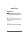
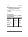
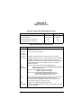
Hardware Installation Guide for the
QLA2300 Board Family
Fibre Channel Host Adapter Boards for the PCI Bus
Part of the SANblade Family of Products
FC2251101-00 D
October 5, 2001
QLogic Corporation
Information furnished in this manual is believed to be accurate and reliable.
However, QLogic Corporation assumes no responsibility for its use, nor for any
infringements of patents or other rights of third parties which may result from its use.
QLogic Corporation reserves the right to change product specifications at any time
without notice. Applications described in this document for any of these products
are for illustrative purposes only. QLogic Corporation makes no representation nor
warranty that such applications are suitable for the specified use without further
testing or modification. QLogic Corporation assumes no responsibility for any errors
that may appear in this document.
No part of this document may be copied nor reproduced by any means, nor
translated nor transmitted to any magnetic medium without the express written
consent of QLogic Corporation.
Microsoft, Windows NT, and Windows 2000 are trademarks of Microsoft
Corporation.
QLogic is a trademark of QLogic Corporation.
Seagate is a trademark of Seagate Technology, Inc.
SunSPARC is a trademark of SPARC International, Inc. Products bearing
SPARC trademarks are based on an architecture developed by Sun
Microsystems, Inc.
All other brand and product names are trademarks or registered trademarks of
their respective owners.
Document Revision History
Rev. A, initial release, 12/11/00
Rev. B, update, 3/2/01, (QLA2310/QLA2310F boards added)
Rev C, update, 7/31/01, (QLA2310FL/QLA2312F/QLA2312FL boards added)
Rev D, update, 10/5/01 (corrected QLA2310/2310F/2310FL boards’ PCI-X bus
speed from 133 MHz to 66 MHz)
Boards Affected
QLA2300
QLA2300F
QLA2302F
QLA2310
QLA2310F
QLA2310FL
QLA2312F
QLA2312FL
Page ii
FC2251101-00 D
QLogic Corporation
Page iii
FC2251101-00 D
QLogic Corporation
© 2000–2001 QLogic Corporation
First Printed: July 2000
All Rights Reserved Worldwide.
Printed in U.S.A.
QLogic Corporation, 26600 Laguna Hills Drive, Aliso Viejo, CA 92656
(800) 867-7274 or (949) 389-6000
Page iv
FC2251101-00 D
Table of Contents
Section 1
1.1
1.2
1.3
Introduction
General Description. . . . . . . . . . . . . . . . . . . . . . . . . . . . . . . .
What is Fibre Channel? . . . . . . . . . . . . . . . . . . . . . . . . . . . . .
Features . . . . . . . . . . . . . . . . . . . . . . . . . . . . . . . . . . . . . . . .
Section 2
2.1
2.2
2.3
2.3.1
2.3.2
2.4
2.5
2.6
Hardware Installation
Preinstallation Procedures. . . . . . . . . . . . . . . . . . . . . . . . . . .
What You Need for Installation . . . . . . . . . . . . . . . . . . . . . . .
QLA23xx Board Components . . . . . . . . . . . . . . . . . . . . . . . .
LEDs . . . . . . . . . . . . . . . . . . . . . . . . . . . . . . . . . . . . . . . .
Jumpers . . . . . . . . . . . . . . . . . . . . . . . . . . . . . . . . . . . . . .
Power Distribution . . . . . . . . . . . . . . . . . . . . . . . . . . . . . . . . .
Installation in the Computer. . . . . . . . . . . . . . . . . . . . . . . . . .
Installation Help . . . . . . . . . . . . . . . . . . . . . . . . . . . . . . . . . . .
Section 3
3.1
3.2
3.3
3.4
2-1
2-1
2-1
2-5
2-6
2-6
2-6
2-8
Troubleshooting
Problems After Installation. . . . . . . . . . . . . . . . . . . . . . . . . . .
Hardware Problem Checklist . . . . . . . . . . . . . . . . . . . . . . . . .
System Configuration Problem Checklist . . . . . . . . . . . . . . .
Fibre Channel Problem Checklist . . . . . . . . . . . . . . . . . . . . .
Appendix A
A.1
A.2
A.2.1
A.2.2
A.2.3
A.2.4
A.2.5
A.2.6
A.3
A.4
A.5
1-1
1-1
1-2
Fast!UTIL
Introduction . . . . . . . . . . . . . . . . . . . . . . . . . . . . . . . . . . . . . .
Configuration Settings . . . . . . . . . . . . . . . . . . . . . . . . . . . . .
Host Adapter Settings . . . . . . . . . . . . . . . . . . . . . . . . . . .
Selectable Boot Settings . . . . . . . . . . . . . . . . . . . . . . . . .
Restore Default Settings . . . . . . . . . . . . . . . . . . . . . . . . .
Raw NVRAM Data . . . . . . . . . . . . . . . . . . . . . . . . . . . . . .
Advanced Adapter Settings . . . . . . . . . . . . . . . . . . . . . . .
Extended Firmware Settings . . . . . . . . . . . . . . . . . . . . . .
Scan Fibre Channel Devices . . . . . . . . . . . . . . . . . . . . . . . .
Fibre Disk Utility . . . . . . . . . . . . . . . . . . . . . . . . . . . . . . . . . .
Select Host Adapter . . . . . . . . . . . . . . . . . . . . . . . . . . . . . . .
Appendix B
Specifications
Appendix C
Label
FC2251101-00 D
3-1
3-1
3-1
3-2
A-1
A-1
A-2
A-2
A-3
A-3
A-3
A-5
A-7
A-7
A-7
Page v
Table of Contents
Hardware Installation Guide for the QLA2300 Board Family
FIGURES
Figure
2-1
2-2
2-3
2-4
2-5
2-6
2-7
2-8
Page
QLA2300/2310 Board Layout . . . . . . . . . . . . . . . . . . . . . . . . . . .
QLA2300F/2310F Board Layout . . . . . . . . . . . . . . . . . . . . . . . . .
QLA2310FL Board Layout . . . . . . . . . . . . . . . . . . . . . . . . . . . . .
QLA2302F Board Layout . . . . . . . . . . . . . . . . . . . . . . . . . . . . . .
QLA2312F Board Layout . . . . . . . . . . . . . . . . . . . . . . . . . . . . . .
QLA2312FL Board Layout . . . . . . . . . . . . . . . . . . . . . . . . . . . . .
QLA2300/2300F/2310/2310F/2310FL Board LED Activity . . . . .
QLA2302F/2312F Board LED Activity. . . . . . . . . . . . . . . . . . . . .
2-2
2-2
2-3
2-3
2-4
2-4
2-5
2-5
TABLES
Table
A-1
A-2
A-3
A-4
A-5
B-1
B-2
Page vi
Page
Host Adapter Settings . . . . . . . . . . . . . . . . . . . . . . . . . . . . . . . . .
Advanced Adapter Settings. . . . . . . . . . . . . . . . . . . . . . . . . . . . .
Extended Firmware Settings . . . . . . . . . . . . . . . . . . . . . . . . . . . .
RIO Operation Modes . . . . . . . . . . . . . . . . . . . . . . . . . . . . . . . . .
Connection Options. . . . . . . . . . . . . . . . . . . . . . . . . . . . . . . . . . .
QLA23xx Board Operating Environment. . . . . . . . . . . . . . . . . . .
QLA23xx Board Specifications . . . . . . . . . . . . . . . . . . . . . . . . . .
A-2
A-3
A-5
A-6
A-6
B-1
B-1
FC2251101-00 D
Section 1
Introduction
NOTE: The following SANblade QLogic host adapter boards are collectively
referred to as the QLA23xx board unless otherwise noted:
■
QLA2300 family (64-bit PCI to Fibre Channel copper media)
■
QLA2300F family (64-bit PCI to Fibre Channel optical media)
■
QLA2302F family (64-bit PCI to dual-channel optical media)
■
QLA2310 family (64-bit PCI-X to Fibre Channel copper media)
■
QLA2310F family (64-bit PCI-X to Fibre Channel optical media)
■
QLA2310FL family (64-bit PCI-X to Fibre Channel optical media, low
profile)
■
QLA2312F family (64-bit PCI-X to dual-channel Fibre Channel optical
media)
■
QLA2312FL family (64-bit PCI-X to dual-channel Fibre Channel optical
media, low profile)
1.1
General Description
Thank you for selecting the QLA23xx Fibre Channel (FC) board. The QLA23xx
board is an intelligent, high-performance, DMA bus master host adapter designed
for high-end systems. The intelligence and performance are derived from the
ISP2300/2310/2312 chips, making the QLA23xx board a leading-edge host adapter.
The ISP2300/2310/2312 combines a powerful RISC processor, a Fibre Channel
protocol manager (FPM) with one 2-Gb Fibre Channel transceiver, and a peripheral
component interconnect (PCI) or peripheral component interconnect-extended
(PCI-X) local bus interface in a single-chip solution. The QLA23xx board supports
all FC peripherals that support private loop direct attach (PLDA) and fabric loop
attach (FLA). Installation of the QLA23xx board is quick and easy.
1.2
What is Fibre Channel?
Fibre Channel technology is outlined in the SCSI-3 Fibre Channel Protocol
(SCSI-FCP) standard. Fibre Channel is a high-speed data transport technology
used for mass storage and networking. It connects mainframes, super computers,
workstations, storage devices, and servers.
Fibre Channel supports data transfer rates up to 200 MBps half-duplex and
400 MBps full-duplex on copper and optical interfaces. The QLA2300 and QLA2310
FC2251101-00 D
1-1
Features
1 – Introduction
boards use a copper interface for short connections (less than 30 meters at a data
rate of 1 Gbps; less than 15 meters at a data rate of 2 Gbps). The following boards
use a multimode optical interface for intermediate distances (less than 500 meters
at the data rate of 1 Gbps; less than 300 meters at the data rate of 2 Gbps).
■
■
■
■
■
■
QLA2300F
QLA2302F
QLA2310F
QLA2310FL
QLA2312F
QLA2312FL
With its increased connectivity and performance, Fibre Channel is the I/O
technology preferred and used by system designers.
1.3
Features
1-2
■
Compliance with PCI Local Bus Specification revision 2.2
■
Compliance with PCI-X Addendum (revision 1.0) to the PCI Local Bus
Specification (QLA2310/2310F/2310FL/2312F/2312FL)
■
Compliance with Third Generation Fibre Channel-Physical and Signaling
Interface (FC-PH-3) standard
■
Compliance with Fibre Channel-Arbitrated Loop (FC-AL-2) standard
■
Compliance with U.S. and international safety and emissions standards
■
Support for bus master DMA
■
Fast!UTIL BIOS utility to customize the configuration parameters on the
QLA23xx board and attached drives
■
Two independent channels on a single board (QLA2302F)
■
Supports Fibre Channel protocol-SCSI (FCP-SCSI), IP, and Fibre
Channel-virtual interface (FC-VI) protocols
■
Supports point-to-point fabric connection (F-PORT FABRIC LOGIN)
FC2251101-00 D
Section 2
Hardware Installation
2.1
Preinstallation Procedures
Before installing your QLA23xx board, take a moment to read this guide.
CAUTION! The QLA23xx board contains parts that can be damaged by ESD.
Before handling the QLA23xx board, use standard methods to
discharge static electricity. Keep the QLA23xx board in the antistatic
bag until you are ready to install it. Place the board on the bag when
you examine or configure it. Retain the bag for future use.
2.2
What You Need for Installation
Before you install the QLA23xx board in your computer, you need the following:
■
A screwdriver (usually a Phillips #1)
■
A high-speed, serial data connector (HSSDC) cable that is compatible with
data rates of 2 Gbps for the QLA2300 and QLA2310 boards
■
An optical mutimode cable with an LC-style duplex connector for the
QLA2300F/2310F/2310FL boards; two cables for the QLA2302F/2312F/
2312FL boards.
2.3
QLA23xx Board Components
Figures 2-1 through 2-4 identify the QLA23xx board components referenced
throughout this section.
Each QLA23xx board has a unique serial number; its location on the board is noted
in figures 2-1 through 2-4. Take a minute to write down the serial number of the
QLA23xx board.
FC2251101-00 D
2-1
QLA23xx Board Components
2 – Hardware Installation
SERIAL NUMBER
J1
ISP CHIP
Figure 2-1. QLA2300/2310 Board Layout
SERIAL NUMBER
J1
ISP CHIP
Figure 2-2. QLA2300F/2310F Board Layout
2-2
FC2251101-00 D
2 – Hardware Installation
QLA23xx Board Components
ISP CHIP
J2
J2
1
3
NOTE: The serial number is on the other
side of the board.
Figure 2-3. QLA2310FL Board Layout
ISP CHIP
J1
J2
ISP CHIP
SERIAL NUMBER
Figure 2-4. QLA2302F Board Layout
FC2251101-00 D
2-3
QLA23xx Board Components
2 – Hardware Installation
SERIAL NUMBER
J1
1
3
J2
J3
ISP CHIP
J4
1
3
Figure 2-5. QLA2312F Board Layout
J3
1
3
J1
ISP CHIP
J2
J4
1
3
NOTE: The serial number is on the other
side of the board.
Figure 2-6. QLA2312FL Board Layout
2-4
FC2251101-00 D
2 – Hardware Installation
QLA23xx Board Components
2.3.1
LEDs
Figure 2-7 identifies and describes the activity of the QLA2300/2300F/2310/2310F/
2310FL board LEDs. Figure 2-8 identifies and describes the activity of the
QLA2302F/2312F board LEDs. The QLA2312FL board has no LEDs.
CONNECTOR
GREEN LED
AMBER LED
Green
LED
Amber
LED
On
On
Power
On
Off
Online
Off
On
Signal acquired
Off
Flashing
Loss of synchronization
Flashing
Flashing
Firmware error
Activity
Figure 2-7. QLA2300/2300F/2310/2310F/2310FL Board LED Activity
J1 CONNECTOR
J2 CONNECTOR
J1 CONNECTOR LEDs
J2 CONNECTOR LEDs
GREEN LED
AMBER LED
Green
LED
Amber
LED
On
On
Power
On
Off
Online
Off
On
Signal acquired
Off
Flashing
Loss of synchronization
Flashing
Flashing
Firmware error
Activity
Figure 2-8. QLA2302F/2312F Board LED Activity
FC2251101-00 D
2-5
Power Distribution
2 – Hardware Installation
2.3.2
Jumpers
The jumpers on the QLA2310FL/2312F/2312FL boards set the default state of the
laser and are set at the factory with a jumper plug on pins 1–2 of the following
jumpers.
■
■
■
QLA2310FL (jumper J2)
QLA2312F (jumpers J1 and J4)
QLA2312FL (jumpers J3 and J4)
CAUTION! Changing the jumper settings can result in the board being inoperable.
2.4
Power Distribution
The QLA2300 and QLA2310 boards supply +5 volts to pin 7 of the HSSDC copper
interface to support an external media interface adapter (MIA), if required. (An MIA
converts electrical bus signals to optical bus signals.)
2.5
Installation in the Computer
Perform the following steps to install the QLA23xx board in your PC:
1. Check the motherboard and make any configuration changes necessary to
accommodate the QLA23xx board.
The QLA23xx board is self-configuring; however, some motherboards
require manual configuration. For example, some systems have a PCI
Device Configuration menu in the motherboard setup BIOS where you
must enable host adapter boards, bus master slots, and IRQ levels. If the
motherboard supports triggering, use level triggering for the QLA23xx
board. See the documentation supplied with your computer, or contact your
computer dealer to determine if your motherboard requires configuration.
2. Power down the peripherals, then the computer.
3. Remove the computer cover and save the screws.
4. Choose any PCI bus slot that supports bus mastering. Most motherboards
automatically assign an IRQ level and interrupt line; if your motherboard
does not, you must assign the IRQ level and use interrupt line A for this slot.
NOTE:
■
2-6
Some motherboards have two kinds of PCI bus slots: master
and slave. The QLA23xx board must be in a PCI bus master
slot. (Some motherboards have PCI bus master slots that are
shared with onboard devices. QLA23xx boards do not work in
shared slots.)
FC2251101-00 D
2 – Hardware Installation
Installation in the Computer
■
PCI connectors vary among system board manufacturers. The
QLA23xx board is a 64-bit PCI device that can function in a
32-bit PCI slot; the slot conforms to the PCI specification (the
rear edge of the PCI slot is notched). If you try to install the
QLA23xx board into a PCI slot that does not conform to the PCI
specification, you may damage the QLA23xx board.
■
PCI and PCI-X slots look the same. If the PC contains both PCI
and PCI-X slots, refer to the PC manufacturer’s instructions to
determine the slot type.
■
The QLA2300/2300F/2302F boards are designed and tested to
operate at PCI bus speeds of up to 66 MHz.
■
The QLA2310/2310F/2310FL boards are designed and tested
to operate at PCI-X bus speeds up to 66 MHz.
■
The QLA2312F/2312FL boards are designed and tested to
operate at PCI-X bus speeds of up to 133 MHz.
5. Remove the slot cover for the slot in which you will install the QLA23xx
board.
6. Place the QLA23xx board into the slot. Carefully press the board into the
slot until it seats firmly.
7. Secure the QLA23xx board to the chassis. Follow the PC manufacturer’s
instructions.
8. Connect the appropriate cable from the devices to the corresponding
connector.
9. Carefully reinstall the computer cover. Insert and tighten the computer cover
screws.
FC2251101-00 D
2-7
Installation Help
2 – Hardware Installation
10. Power up all external FC devices, then power up the PC and observe the
monitor. The BIOS is disabled by default. Consequently, the devices
attached to the QLA23xx board are not identified. For example:
QLogic Corporation
QLA23xx PCI Fibre Channel ROM BIOS Version x.xx
Copyright (C) QLogic Corporation 2000 All rights reserved.
www.qlogic.com
Press <Alt-Q> for Fast!UTIL
BIOS for Adapter 0 is disabled
ROM BIOS not installed
NOTE:
■
SunSPARC systems do not display the BIOS banner.
■
Enable the BIOS only if the boot device is attached to the
QLA23xx board. This allows the system to boot faster.
■
For further information about enabling the QLA23xx board
BIOS, see appendix A.
If the information displayed on your monitor is correct, congratulations! You have
successfully installed the QLA23xx board in your computer.
See the Software Installation Guide for the QLA2300 Board Family (FC2253301-00)
for detailed instructions on how to install the software drivers.
If the information displayed is not correct and you have checked the QLA23xx
board’s configuration, see section 3 for troubleshooting information.
2.6
Installation Help
If your system has an IDE hard disk, it may be assigned device number 80, which
is the boot device. If your system does not have an IDE hard disk, a parallel SCSI
host bus adapter (HBA), or a RAID adapter, the first bootable FC hard disk
configured (the one with the lowest ID) is assigned device number 80 and becomes
the boot device. The QLA23xx board BIOS must be enabled if the boot device is
connected to the QLA23xx board.
If you have a selectable boot BIOS and want to boot to an FC hard disk, set the
motherboard BIOS parameters to None or Not Installed. The ROM BIOS on the
QLA23xx board automatically configures the FC peripherals.
Some new system BIOSs support selectable boot, which supersedes the QLA23xx
board BIOS selectable boot setting. Select the QLA23xx board FC hard disk in the
system BIOS to boot from an FC hard disk attached to the QLA23xx board.
2-8
FC2251101-00 D
Section 3
Troubleshooting
3.1
Problems After Installation
There are three basic types of installation problems that can cause your QLA23xx
board to function incorrectly: hardware problems, system configuration problems,
and Fibre Channel problems. The following section provides itemized checklists to
help you determine why your QLA23xx board is not functioning.
3.2
Hardware Problem Checklist
■
Are all of the circuit cards installed securely in the system?
■
Are all of the cables securely connected to the correct connectors? Be sure
that the FC cables that attach from the QLA23xx board connectors to the
device are connected correctly. For example, the optical transmit connector
on the QLA23xx board must be connected to the optical receive connector
on the device. Some connectors require a firm push to ensure proper seating.
An easy way to check for correct seating is to switch the connectors on either
the QLA23xx board or the device, then reboot your system. If the BIOS is
enabled, devices attached to the QLA23xx board are displayed on the
screen.
■
Is the QLA23xx board installed correctly in the PCI slot? Is it seated firmly
in the slot?
■
Check for interference due to nonstandard PCI connectors.
■
Is the Fast!UTIL data rate setting correct? See section A.2.6 for information
about setting the data rate.
■
Are all external peripherals properly powered up? See section A.3 for
information about displaying attached devices.
3.3
System Configuration Problem Checklist
All PCI-compliant and PCI-X-compliant systems automatically detect 32-bit or 64-bit
boards and set the appropriate bus speed (for example, 33 MHz or 66 MHz). Check
the motherboard for proper configuration (see section 2.5).
See the documentation supplied with your computer, or contact your computer
dealer to determine if your motherboard requires special configuration.
FC2251101-00 D
3-1
Fibre Channel Problem Checklist
3 – Troubleshooting
3.4
Fibre Channel Problem Checklist
3-2
■
Were all of the FC devices powered up before you powered up the PC?
■
Check that all cables are properly connected.
■
If you are using an HSSDC cable, verify that it is compatible with data rates
of 2 Gbps.
■
Have you configured your RAID controller using the utilities provided by the
manufacturer?
■
Some Fibre Channel switches support zoning. Make sure that your switch
is configured correctly.
FC2251101-00 D
Appendix A
Fast!UTIL
NOTE: The Fast!UTIL BIOS utility does not run on SunSPARC systems. Refer to
the Software Installation Guide for the QLA2300 Board Family
(FC2253301) for information regarding adapter configuration settings and
for installing FCode on a QLA23xx board in a SunSPARC system.
A.1
Introduction
This appendix provides detailed configuration information for advanced users who
want to customize the configuration of the QLA23xx board and the connected
devices.
The QLA23xx board can be configured using Fast!UTIL, QLogic’s BIOS-resident
configuration tool. Access Fast!UTIL by pressing ALT+Q during the QLA23xx board
BIOS initialization (it may take a few seconds for the Fast!UTIL Options menu to
display). If you have more than one QLA23xx board, Fast!UTIL asks you to select
the QLA23xx board you want to configure. After changing the settings and exiting
the utility, Fast!UTIL reboots your system to load the new parameters.
CAUTION! If the configuration settings are incorrect, your QLA23xx board may
not function properly.
The following sections describe the Fast!UTIL options.
A.2
Configuration Settings
The first selection on the Fast!UTIL Options menu is Configuration Settings.
These settings configure the FC devices and the QLA23xx board to which they are
attached.
FC2251101-00 D
A-1
Configuration Settings
A – Fast!UTIL
A.2.1
Host Adapter Settings
From the Configuration Settings menu in Fast!UTIL, select Host Adapter
Settings. The default settings for the QLA23xx board are listed in table A-1 and
described in the following paragraphs.
Table A-1. Host Adapter Settings
Setting
Options
Default
Host Adapter BIOS
Enabled, Disabled
Disabled
Frame Size
512, 1024, 2048
Loop Reset Delay
0–60 seconds
Adapter Hard Loop ID
Enabled, Disabled
Hard Loop ID
0–125
2048
5 seconds
Disabled
0
■
Host Adapter BIOS. When this setting is Disabled, the ROM BIOS on the
QLA23xx board is disabled, freeing space in upper memory. This setting
must be enabled if you are booting from an FC hard disk attached to the
QLA23xx board. The default is Disabled.
■
Frame Size. This setting specifies the maximum frame length supported by
the QLA23xx board. The default size is 2048, which provides maximum
performance for F-Port (point-to-point) connections.
■
Loop Reset Delay. After resetting the loop, the firmware refrains from
initiating any loop activity for the number of seconds specified in this setting.
The default is 5 seconds.
■
Adapter Hard Loop ID. This setting forces the adapter to attempt to use
the ID specified in the Hard Loop ID setting. The default is Disabled.
■
Hard Loop ID. If the Adapter Hard Loop ID setting is enabled, the adapter
attempts to use the ID specified in this setting. The default ID is 0.
A.2.2
Selectable Boot Settings
The Selectable Boot Settings option is accessed from the Configuration Settings
menu. If you enable this option, you can select the node name from which you want
to boot. Once enabled, this option forces the system to boot on the selected FC
hard disk, ignoring any IDE hard disks attached to your system. If you disable this
option, the system looks for a boot device (as selected in the system BIOS). In
disabled mode, the Boot ID and Boot LUN parameters have no effect.
A-2
FC2251101-00 D
A – Fast!UTIL
Configuration Settings
Some new system BIOSs support selectable boot, which supersedes the Fast!UTIL
selectable boot setting. To boot from an FC hard disk attached to the QLA23xx
board, select the QLA23xx board FC hard disk on the system BIOS.
NOTE: This option applies only to hard disks; it does not apply to tape drives and
other nondisk devices.
A.2.3
Restore Default Settings
The Restore Defaults option from the Configuration Settings menu restores the
QLA23xx board default settings.
A.2.4
Raw NVRAM Data
This option displays the adapter’s NVRAM contents in hexadecimal format. This is
a QLogic troubleshooting tool; you cannot modify the data.
A.2.5
Advanced Adapter Settings
From the Configuration Settings menu in Fast!UTIL, select Advanced Adapter
Settings. The default settings for the QLA23xx board are listed in table A-2 and
described in the following paragraphs.
Table A-2. Advanced Adapter Settings
Setting
Options
Default
Execution Throttle
1–256
Fast Command Posting
Enabled, Disabled
Disabled
>4GByte Addressing
Enabled, Disabled
Disabled
Luns per Target
0, 8, 16, 32, 64, 128, 256
Enable LIP Reset
Yes, No
No
Enable LIP Full Login
Yes, No
Yes
Enable Target Reset
Yes, No
No
Login Retry Count
0–255
8
Port Down Retry Count
0–255
8
Drivers Load RISC Code
Enabled, Disabled
Enable Database Updates
Yes, No
No
Disable Database Load
Yes, No
No
IOCB Allocation
1–512 buffers
Extended Error Logging
Enabled, Disabled
FC2251101-00 D
16
8
Enabled
256 buffers
Disabled
A-3
Configuration Settings
A – Fast!UTIL
■
Execution Throttle. This setting specifies the maximum number of
commands executing on any one port. When a port’s execution throttle is
reached, no new commands are executed until the current command
finishes executing. The valid options for this setting are 1–256. The default
is 16.
■
Fast Command Posting. This setting decreases command execution time
by minimizing the number of interrupts. The default is Disabled.
■
>4GByte Addressing. This option should be Enabled if the system has
more than 4 GB of memory available. The default is Disabled.
■
LUNs per Target. This setting specifies the number of LUNs per target.
Multiple LUN support is typically for RAID boxes that use LUNs to map drives.
The default is 8. If you do not need multiple LUN support, set the number of
LUNs to 0.
■
Enable LIP Reset. This setting determines the type of loop initialization
process (LIP) reset that is used when the operating system initiates a bus
reset routine. When this setting is Yes, the driver initiates a global LIP reset
to clear the target device reservations. When this setting is No, the driver
initiates a global LIP reset with full login. The default is No.
■
Enable LIP Full Login. This setting instructs the ISP chip to re-login to all
ports after any LIP. The default is Yes.
■
Enable Target Reset. This setting enables the drivers to issue a Target
Reset command to all devices on the loop when a SCSI Bus Reset command
is issued. The default is No.
■
Login Retry Count. This setting specifies the number of times the software
tries to log in to a device. The default is 8 retries.
■
Port Down Retry Count. This setting specifies the number of times the
software retries a command to a port returning port down status. The default
is 8 retries.
■
Drivers Load RISC Code. When this setting is Enabled, the QLA23xx board
uses the RISC firmware that is embedded in the software driver. When this
setting is Disabled, the software driver loads the RISC firmware that is stored
in the QLA23xx board BIOS. The default is Enabled.
NOTE: The driver being loaded must support this setting. If the driver does
not support this setting, the result is the same as Disabled
regardless of the setting. Leaving this option enabled guaranties a
certified combination of software driver and RISC firmware.
■
A-4
Enable Database Updates. When enabled, this setting allows the software
to save the loop configuration information in flash memory when the system
powers down. The default is No.
FC2251101-00 D
A – Fast!UTIL
■
Configuration Settings
Disable Database Load. When enabled, the device database is read from
the Registry during driver initialization. When disabled, the device database
is created dynamically during driver initialization. The default is No.
NOTE: This option usually applies to the Windows NT and Windows 2000
operating environments.
■
IOCB Allocation. This setting specifies the maximum number of buffers
from the firmware’s buffer pool that are allocated to any one port. The default
is 256 buffers.
■
Extended Error Logging. This setting provides additional error and debug
information to the operating system. When Enabled, events are logged into
the Windows NT/Windows 2000 Event Viewer. The default is Disabled.
A.2.6
Extended Firmware Settings
From the Configuration Settings menu in Fast!UTIL, select Extended Firmware
Settings. The default settings for the QLA23xx board are listed in table A-3 and
described in the following paragraphs.
Table A-3. Extended Firmware Settings
Setting
Options
Default
Extended Control Block
Enabled, Disabled
Enabled
RIO Operation Mode
0, 1, 2, 3, 4
0
Connection Options
0, 1, 2
2
Class 2 Service
Enabled, Disabled
Disabled
ACK0
Enabled, Disabled
Disabled
Fibre Channel Tape Support
Enabled, Disabled
Disabled
Fibre Channel Confirm
Enabled, Disabled
Disabled
Command Reference Number
Enabled, Disabled
Disabled
Read Transfer Ready
Enabled, Disabled
Disabled
Response Timer
0–255
0
Interrupt Delay Timer
0–255
0
Data Rate
0, 1, 2
0
FC2251101-00 D
A-5
Configuration Settings
A – Fast!UTIL
■
Extended Control Block. This setting enables all other extended firmware
settings. The default is Enabled.
■
RIO Operation Mode. This setting specifies the reduced interrupt operation
(RIO) modes, if supported by the software driver. RIO modes allow posting
multiple command completions in a single interrupt (see table A-4). The
default is 0.
Table A-4. RIO Operation Modes
Option
■
Operation Mode
0
No multiple responses
1
Multiple responses, 16-bit handles, interrupt host
2
Multiple responses, 32-bit handles, interrupt host
3
Multiple responses, 16-bit handles, delay host interrupt
4
Multiple responses, 32-bit handles, delay host interrupt
Connection Options. This setting defines the type of connection (loop or
point-to-point) or connection preference (see table A-5). The default is 2.
Table A-5. Connection Options
Option
Type of Connection
0
Loop only
1
Point-to-point only
2
Loop preferred, otherwise point-to-point
■
Class 2 Service. This setting enables Class 2 service parameters to be
provided during all automatic logins (loop ports). The default is Disabled.
■
ACK0. This setting determines the type of ACK used. When this setting is
Enabled, sequence ACK is used. When this setting is Disabled, frame ACK
is used. The default is Disabled.
NOTE: The Class 2 Service setting must be Enabled to use the ACK0
setting.
A-6
■
Fibre Channel Tape Support. This setting enables FCP-2 recovery. The
default is Disabled.
■
Fibre Channel Confirm. This setting enables the host to send the FCP
confirmation frame when requested by the target. The default is Disabled.
This setting must be Enabled if the Fibre Channel Tape Support setting is
Enabled.
■
Command Reference Number. This setting is reserved. The default is
Disabled.
FC2251101-00 D
A – Fast!UTIL
Select Host Adapter
■
Read Transfer Ready. This setting is reserved. The default is Disabled.
■
Response Timer. This setting contains the value (in 100-microsecond
increments) used by a timer to limit the time waiting accumulating multiple
responses. For example, if this field is 8, the time limit is 800 microseconds.
The default is 0.
■
Interrupt Delay Timer. This setting contains the value (in 100-microsecond
increments) used by a timer to set the wait time between accessing (DMA)
a set of handles and generating an interrupt. The default is 0.
■
Data Rate. This setting determines the data rate. When this setting is 1, the
QLA23xx board runs at 2 Gbps. When this setting is 2, Fast!UTIL determines
what rate your system can accommodate and sets the rate accordingly. The
default is 0 (the QLA23xx board runs at 1 Gbps).
A.3
Scan Fibre Channel Devices
This option scans the FC loop and lists all the connected devices by loop ID.
Information about each device is listed, for example, vendor name, product name,
and revision. This information is useful when configuring your QLA23xx board and
attached devices.
A.4
Fibre Disk Utility
This option scans the FC loop and lists all the connected devices by loop ID. You
can select a hard disk and perform a low-level format or verify the hard disk.
CAUTION! Performing a low-level format destroys all data on the hard disk.
A.5
Select Host Adapter
If you have multiple QLA23xx boards in your system, use this setting to select and
then configure or view the settings of a specific QLA23xx board.
FC2251101-00 D
A-7
Select Host Adapter
A-8
A – Fast!UTIL
FC2251101-00 D
Appendix B
Specifications
Table B-1. QLA23xx Board Operating Environment
Environment
Operating temperature
Minimum
Maximum
0°C/32°F
55°C/131°F
-20 °C/-4 °F
70°C/158°F
Relative humidity (noncondensing)
10%
90%
Storage humidity (noncondensing)
5%
95%
Storage temperature
Table B-2. QLA23xx Board Specifications
Type
Specification
Host bus
Conforms to PCI Local Bus Specification, revision 2.2 and the PCI-X
Addendum, revision 1.0
PCI/PCI-X
signaling
environment
3.3 V and 5.0 V buses supported
PCI/PCI-X
transfer rate
132 MBps maximum burst rate for 32-bit PCI operation at 33 MHz
264 MBps maximum burst rate for 32-bit PCI/PCI-X operation at 66 MHz
264 MBps maximum burst rate for 64-bit PCI operation at 33 MHz
528 MBps maximum burst rate for 64-bit PCI/PCI-X operation at 66 MHz
1GBps maximum burst rate for 64-bit PCI-X operation at 133 MHz
(QLA2312F/2312FL)
Fibre
Channel
specifications
Bus type: Copper media, twisted pair (QLA2300/QLA2310)
Multimode fibre optic media (QLA2300F/QLA2302F/QLA2310F/
QLA2312F/QAL2312FL)
Bus transfer rate: 200 MBps maximum at half-duplex
400 MBps maximum at full-duplex
Interface chip: ISP2300 (PCI QLA2300/2300F/2302F boards)
ISP2310 (PCI-X QLA2310/2310F/2310FL boards)
ISP2312 (PCI-X QLA2312F/2312FL boards)
CPU
Single-chip design that includes a QLogic RISC processor, Fibre Channel
protocol manager, PCI/PCI-X DMA controller, and integrated
serializer/deserializer (SERDES) and electrical transceivers that can
auto-negotiate a data rate of 1 Gbps or 2 Gbps
RAM
256 KB of sync SRAM supporting parity protection
BIOS ROM
128 KB of flash ROM in two 64-KB, software selectable banks. The flash
is field programmable.
FC2251101-00 D
B-1
B – Specifications
Table B-2. QLA23xx Board Specifications (Continued)
Type
Specification
NVRAM
256 bytes, field programmable
Onboard
DMA
Five-channel DMA controller: two data, one command, one auto-DMA
request, and one auto-DMA response
Frame buffer
FIFO
Integrated 4-KB transmit and 6-KB receive frame buffer FIFO for each data
channel
Connectors
QLA2300/QLA2310: HSSDC connector that supports copper cabling. Fibre
optic support available using an external MIA
QLA2300F/QLA2310F: LC-style connector that supports non-OFC,
multimode fibre optic cabling using a small form factor optical transceiver
module
QLA2302F: Two LC-style connectors for multimode fibre optic cabling using
a small form factor optical transceiver module
Form factor
17.78 cm× 10.67 cm (7.0"×4.2") (QLA2300/2300F/2302F/2310/2310F/
2312F
16.93 cm× 5.15 cm (6.7"×2.5") (QLA2310FL/2312FL)
Operating
power
Less than 15 watts
B-2
FC2251101-00 D
Appendix C
Label
The transceiver on the QLA23xx board is a Class I laser product. It complies with
IEC 825-1 and FDA 21 CFR 1040.10 and 1040.11. The transceiver must be
operated under recommended operating conditions.
CLASS I LASER PRODUCT
FC2251101-00 D
C-1
C – Label
C-2
FC2251101-00 D