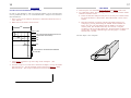
1
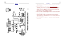
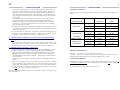
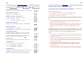
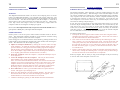
32
1
ELECTROMAGNETIC SHEETMETAL FOLDERS
MAGNABEND - USER MANUAL
for
MODELS 2000E, 2500E & 3200E
Contents
Page
INTRODUCTION ...............................................................................3
ASSEMBLY ........................................................................................4
SPECIFICATIONS..............................................................................6
INSPECTION SHEET.......................................................................10
USING THE MAGNABEND:
OPERATION...............................................................................12
USING BACKSTOPS .................................................................13
FOLDED LIP (HEM) ..................................................................14
ROLLED EDGE ..........................................................................15
MAKING A TEST PIECE...........................................................16
BOXES (SHORT CLAMPBARS)...............................................18
TRAYS (SLOTTED CLAMPBARS) ..........................................21
POWER SHEAR ACCESSORY .................................................22
ACCURACY .....................................................................................23
MAINTENANCE ..............................................................................24
TROUBLE SHOOTING....................................................................25
CIRCUIT ...........................................................................................28
WARRANTY ....................................................................................30
WARRANTY REGISTRATION.......................................................31
MAGNETIC ENGINEERING P/L
32 Browns Road, Kingston
Tasmania 7050
AUSTRALIA
Phone (03) 6229 7599
Fax (03) 6229 7598
Sunday, January 30, 2011
2
31
WARRANTY REGISTRATION
Model No. ___________ Serial No. ___________
Date Purchased __________
Dealer’s Name & Address:
_____________________________________
_____________________________________
_____________________________________
Customer's Name & Address:
_____________________________________
_____________________________________
_____________________________________
_____________________________________
Your answers to the following questions would be appreciated:
(Please underline the appropriate word or words)
How did you learn of the Magnabend ?
Trade Fair, Advertisement, At a School or College, Other _____________
Which is your category of use?
School, Technical College, University, Plumber, Maintenance workshop,
Automotive repair, Electronics workshop, Research support workshop,
Production workshop, Sheetmetal shop, Jobbing workshop,
Other ______________________________________
What type of metal will you usually bend?
Mild Steel, Aluminium, Stainless Steel, Copper, Zinc, Brass
Other ___________________________________
What thickness'?
0.6 mm or less, 0.8 mm. 1.0 mm, 1.2 mm, 1.6 mm
Comments:
(Eg. : Does the machine do what you expected?)
____________________________________________________
____________________________________________________
____________________________________________________
____________________________________________________
____________________________________________________
After completing, please post this form to the address on page 1.
30
3
WARRANTY
The Manufacturer hereby warrants this Magnabend™
bending
machine to be free from defects in materials and/or workmanship for
a period of 12 months.
Our obligation under this Warranty is limited to repairing or replacing faulty parts or materials and does not extend to consequential loss
or damage arising from the use of the machine.
This Warranty does not cover faults that are due to misuse, abuse,
negligence, accident or caused during transportation. Also excluded
are faults arising from unauthorised repair, use not according to
instructions, and normal wear and tear.
Returns under Warranty must be freight-prepaid and, if the Warranty
Registration has not been previously returned, must be accompanied
by proof of the purchase date .
The rights and conditions under this warranty are additional to any
rights that may be conferred under the Trade Practices Act.
Please fill in for your own reference:
Model _________ Serial No. __________ Date Purchased ___________
Dealer's Name and Address:
________________________________
________________________________
________________________________
________________________________
Before returning your machine for repair under warranty, please contact the
Manufacturer to discuss the most efficient means of transport and packaging
and whether the whole or only a part of the machine needs to be returned to
the factory.
To establish proof of purchase date, please return the Warranty Registration
on the following page.
You are advised to contact the Manufacturer before any repairs are undertaken especially when using outside contractors. The Warranty does not
cover the costs of these contractors unless prior arrangements have been
made.
MAGNABEND - INTRODUCTION
The Magnabend sheetmetal bending machine is a highly versatile and easy
to use machine for bending all types of sheetmetal such as aluminium, copper, steel, and stainless steel.
The electromagnetic clamping system provides more freedom to form
the workpiece into complex shapes. It is easy to form very deep narrow
channels, closed sections, and deep boxes that are difficult or impossible on a
conventional machine.
The unique hinging system used for the bending beam provides a completely open-ended machine thus greatly extending its versatility. The stand
design also contributes to the versatility of the machine by providing a "freearm" effect at the ends of the machine.
Ease of use comes from the fingertip control of the clamping and unclamping, the ease and accuracy of bend alignment, and the automatic adjustment
for sheetmetal thickness.
Fundamentally the use of magnetic clamping means that bending loads are
taken right at the point where they are generated; forces do not have to be
transferred to support structures at the ends of the machine. This in turn
means that the clamping member does not need any structural bulk and hence
can be made much more compact and less hindering. (The thickness of the
clampbar is determined only by its requirement to carry sufficient magnetic
flux and not by structural considerations at all).
Special centerless compound hinges have been developed for the Magnabend, and are distributed along the length of the bending beam and thus,
like the clampbar, take bending loads close to where they are generated.
The combined effect of the magnetic clamping with the special centerless
hinges means that the Magnabend is a very compact, space saving, machine
with a very high strength-to-weight ratio.
To get the most out of your machine , users are urged to read this manual, particularly the section titled USING THE MAGNABEND. Please also
return the WARRANTY REGISTRATION as this will simplify any claims
under warranty and also it gives the manufacturer a record of your address
which facilitates keeping customers informed of any developments which
may benefit them.
4
29
ASSEMBLY ...
CIRCUIT
ASSEMBLY INSTRUCTIONS
1. Unpack all items from the box except the main MAGNABEND™
machine.
Locate the packet of fasteners and the 6 mm Allen Key.
2. Using the slings provided, lift up each end of the machine and rest it on
pieces of wood slipped-in across the open top of the box. (Two suitable
pieces of wood are supplied.)
Voltage Tests
Reference point
3. While the machine is in this up-side-down position, attach the columns
using four M8 x 16 cap-head screws. You will need to open-out the
bending beam to gain access to insert two of these screws. Ensure left
and right columns are not interchanged. Columns are correct if the foot
mounting holes are facing outwards.
Test point
4. Attach the feet to their respective columns. (The end with the threaded
screw holes should point towards the rear.) Use four M10 x 16 Buttonhead screws for each foot.
5. Rotate the machine until the tips of the feet are touching the floor and
then, with the aid of an assistant, lift the machine up onto its feet.
6. Install an M10 x 25 cap-head jacking screw into the rear of each foot.
Screw the jacking screws in until the machine is stable.
7. Attach the shelf using four M8 x 16 cap-head screws.
8. Fasten the mains cable-clip to the rear of the right column using an M6 x
10 Phillips-head screw.
9. Attach the tray (with rubber mat) to the centre-rear of the magnet bed
using three M8 x 16 cap-head screws.
10. Install the 4 backstop bars, using two M8 x 17 screws for each bar. Fit a
Stop Collar onto each backstop bar.
11. Attach the left and right lifter handles to the rear of the shaft visible next
to the rear side of the columns. Use one M8 x 20 cap-head screws for
each handle.
12. Rotate the bending beam fully-up, and attach the handle with the angle
scale in the right position using two M8 x 20 cap-head screws. Attach the
other handle in the left position.
13. Install a stop collar on the right handle and lightly clamp it near the top
of the handle.
14. Slip the angle indicator unit onto the right handle. Remove the screws
from both ends of the indicator spindle, attach the 2 arms, and re-tighten
both screws. Note: If these screws are not properly tightened then the
switching mechanism will not work correctly.
15. Install the Footswitch. Remove the rear access panel (8 off M6 x 10
Phillips head screws). Insert the footswitch cable-end through the hole in
the centre of the panel and plug into the spare socket. Install the
footswitch mounting block to the access panel using two M6 x 30 screws.
AC
DC
Any BLUE wire
Any BLACK wire
A
B
C
D
E
LIGHT-Clamping
240
25
+25
+25
-300
condition
V ac
V ac
V dc
V dc
V dc
FULL-Clamping
240
240
+215
+215
-340
condition
V ac
V ac
V dc
V dc
V dc
28
5
CIRCUIT ...
... ASSEMBLY
(These screws may be already loosely installed in the panel.) Re-install
the access panel.
16. Bolt the machine to the floor using two M12 x 60 masonry bolts
(supplied). Using a 12 mm masonry bit drill two holes, at least 60 mm
deep, through the holes in the front of each foot. Insert the masonry bolts
and tighten the nuts. Note: If the machine is to be used for light gauge
bending only (up to 1 mm) then it may not be necessary to bolt it to the
floor, however for heavy bending it is essential.
17. Remove the clear protective coating from the top surface of the machine
and from the underside of the clampbar. A suitable solvent is mineral
turps or petrol (gasoline).
18. Place the clampbar on the backstop bars of the machine, and pull it
forward to engage the heads of the (retracted) lifter pins. Engage the
lifting mechanism by pushing hard back on one of the lifting handles and
then release forwards.
19. Your MAGNABEND is ready for use. Please now read the Operating
Instructions.
6
27
SPECIFICATIONS ...
... TROUBLE SHOOTING
NOMINAL CAPACITY
Machine Weight
Model 2000E:
2000 mm x 1.6 mm (6½ft x 16g)
270 kg
Model 2500E:
2500 mm x 1.6 mm (8ft x 16g)
315 kg
Model 3200E:
3200 mm x 1.2 mm (10½ft x 18g)
380 kg
CLAMPING FORCE
Total force with standard full-length clamp-bar:
Model 2000E:
9 Tonne
Model 2500E:
12 Tonne
Model 3200E:
12 Tonne
ELECTRICAL
1 Phase, 220/240 V AC
Current:
Model 2000E:
12 Amp
Model 2500E:
16 Amp
Model 3200E:
16 Amp
Duty Cycle: 30%
Protection: Thermal cut-out, 70°C
Control:
Start button ...pre-clamping force
Bending beam microswitch...full clamping
Interlock...the start button and the bending beam must be operated in correct overlapping sequence to initiate full-clamping force.
HINGES
Special centerless design to provide a completely open-ended machine.
Rotation angle:
180°
BENDING DIMENSIONS
19mm (min)
19mm
- 98mm (min) Standard Clampbar
- 49mm (min) Narrow Clampbar
Unlimited
19mm (min)
Refer to Chart
26
7
... SPECIFICATIONS ...
... TROUBLE SHOOTING ...
need more clutching force. Lack of clutching force usually relates to
the two M8 cap-head screws at either end of the actuator shaft not being tight. If the actuator rotates and clutches OK but still does not
click the microswitch then it may need adjusting. To do this first unplug the machine from the power outlet and then remove the electrical
access panel.
The turn-on point can be adjusted by turning a screw which passes
through the actuator. The screw should be adjusted such that the
switch clicks when the bottom edge of the bending beam has moved
about 4 mm. (The same adjustment can also be achieved by bending
the arm of the microswitch.)
b) If the microswitch does not click ON and OFF even though the actuator
is working properly then the switch itself may be fused inside and will
need to be replaced.
c) If your machine is fitted with an auxiliary switch then make sure it is
switched to the "NORMAL" position. (Only light clamping will be
available if the switch is in the "AUX CLAMP" position.)
3. Clamping is OK but Clampbars do not release when the machine switches
OFF:
This indicates a failure of the reverse pulse demagnetising circuit. The
most likely cause would be a blown 6.8 Ω power resistor. Also check
all diodes and also the possibility of sticking contacts in the relay.
4. Machine will not bend heavy gauge sheet:
a) Check that the job is within the specifications of the machine. In particular note that for 1.6 mm (16 gauge) bending the extension bar
must be fitted to the bending beam and that the minimum lip width is
30 mm. This means that at least 30 mm of material must project out
from the bending edge of the clampbar. (This applies to both aluminium and steel.)
(Narrower lips are possible if the bend is not the full length of the machine.)
b) Also if the workpiece does not fill up the space under the clampbar
then performance may be affected. For best results always fill up the
space under the clampbar with a scrap piece of steel the same thickness
as the workpiece. (For best magnetic clamping the filler piece should
be steel even if the workpiece is not steel.)
This is also the best method to use if it is required to make a very narrow lip
on the workpiece.
BENDING CAPABILITY
(When using a standard full-length clamp-bar to bend a full-length workpiece)
MATERIAL
THICKNESS
(yield/ultimate stress)
LIP WIDTH
BEND RADIUS
(minimum)
(typical)
Mild-steel
1.6 mm
30 mm*
3.5 mm
(250/320 MPa)
1.2 mm
15 mm
2.2 mm
1.0 mm
10 mm
1.5 mm
Aluminium
1.6 mm
30 mm*
1.8 mm
Grade 5005 H34
1.2 mm
15 mm
1.2 mm
(140/160 MPa)
1.0 mm
10 mm
1.0 mm
Stainless Steel
1.0 mm
30 mm*
3.5 mm
Grades 304, 316
0.9 mm
15 mm
3.0 mm
(210/600 MPa)
0.8 mm
10 mm
1.8 mm
* With extension bar fitted to bending beam.
SHORT CLAMP-BAR SET
Lengths:: 25, 38, 52, 70, 140, 280, 597, 1160 mm
All sizes (except 597 mm & 1160 mm) may be plugged together to form a
bending edge within 25 mm of any desired length up to 575 mm.
SLOTTED CLAMPBAR
Supplied as an optional extra for forming shallow pans. Has a special set of 8
mm wide by 40 mm deep* slots which provide for forming all tray sizes in
the range 15 to 1265 mm
* For deeper trays use the Short Clamp-bar set.
8
25
... SPECIFICATIONS ...
TROUBLE SHOOTING ...
The easiest way to fix electrical problems is to order a replacement electrical
module from the manufacturer. This is supplied on an exchange basis and
therefore is quite reasonably priced. Before sending for an exchange module
you may like to check the following:
MODELS 2000E & 2500E
1. Machine does not operate at all:
a) Check that power is available at the machine by observing the pilot
light in the ON/OFF switch.
b) If power is available but the machine is still dead but feels very hot
then the thermal cut-out may have tripped. In this case wait until the
machine cools down (about ½ an hour) and then try it again.
FRONT & SIDE ELEVATIONS (mm)
c) The two-handed starting interlock requires that the START button is
pressed before the handle is pulled. If the handle is pulled first then
the machine will not operate. Also it may happen that the bending
beam moves (or is bumped) sufficiently to operate the "angle microswitch" before the START button is pressed. If this happens make
sure the handle is pushed fully back first. If this is a persistent problem
then it indicates that the turn-on point of the microswitch actuator
needs adjustment (see below).
d) Another possibility is that the START button may be faulty. See if the
machine can be started with one of the alternative START buttons or
the footswitch.
e) Also check the connector which connects the electrical module with the
magnet coil.
f) If clamping does not operate but the clampbar snaps down on release of
the START button then this indicates that the 15 microfarad capacitor
is faulty and will need to be replaced.
g) If the machine blows external fuses or trips circuit breakers when operated then the most likely cause is a blown bridge-rectifier.
2. Light clamping operates but full clamping does not:
CROSS-SECTION DETAIL (mm)
a) Check that the "Angle Microswtich" is being actuated correctly.
[This switch is operated by a square brass piece which is attached to
the angle indicating mechanism. When the handle is pulled the bending
beam rotates which imparts a rotation to the brass actuator. The actuator in turn operates a microswitch inside the electrical assembly.]
Pull the handle out and in. You should be able to hear the microswitch
clicking ON and OFF (provided there is not too much background
noise).
If the switch does not click ON and OFF then swing the bending beam
right up so that the brass actuator can be observed . Rotate the bending
beam up and down. The actuator should rotate in response to the bending beam (until it clutches against its stops). If it does not then it may
24
9
... SPECIFICATIONS
MAINTENANCE
WORKING SURFACES
MODEL 3200E
If the bare working surfaces of the machine become rusty, tarnished or damaged, they may be readily reconditioned. Any raised burrs should be filed off
flush, and the surfaces rubbed with P200 emery paper. Finally apply a sprayon anti-rust such as CRC 5.56 or RP7.
HINGE LUBRICATION
If the Magnabend TM sheetmetal folder is in constant use, then grease or oil
the hinges once per month. If the machine is used less, then it may be lubricated less frequently.
Lubrication holes are provided in the two lugs of the main hinge plate, and
the spherical bearing surface of the sector block should also have lubricant
applied to it.
FRONT & SIDE ELEVATIONS (mm)
ADJUSTERS
The adjuster screws at the ends of the main clampbar are to control the allowance for the thickness of the workpiece between the bending-edge and the
bending beam.
Note that the heads for the screws are divided into 3 by one, two and three
centre pop marks. These marks are a useful reference for repeat settings of
the clampbar. If the adjuster screws are both set so that the single pop mark
is uppermost then the bending gap will be approximately 1 mm.
CROSS-SECTION DETAIL (mm)
10
23
INSPECTION SHEET ...
MODEL
SERIAL NO.
ACCURACY
CHECKING THE ACCURACY OF YOUR MACHINE
DATE
All functional surfaces of the Magnabend are manufactured to be straight and
flat to within 0.2 mm over the entire length of the machine.
EARTHING CONNECTIONS
Measure resistance from mains plug earth pin to magnet body ....
ohm
ELECTRICAL ISOLATION
The most critical aspects are:
1. the straightness of the working surface of the bending beam,
Megger from coil to magnet body .............................................
2. the straightness of the bending edge of the clampbar, and
3. the parallelism of these two surfaces.
MIN/MAX SUPPLY VOLTAGE TESTS
These surfaces can be checked with a precision straight-edge but another
good method of checking is to reference the surfaces to each other. To do
this:
1. Swing the bending beam up to the 90° position and hold it there. (The
beam can be locked in this position by placing a back-stop clamp collar
behind the angle slide on the handle).
At 260v: Pre-clamp.... full-clamp.... release .............................
At 200v: Pre-clamp.... release .................................................
Pre-clamp.... full-clamp.... release .............................
INTERLOCK SEQUENCE
2. Observe the gap between the bending edge of the clamp bar and the working surface of the bending beam. Using the clampbar adjusters set this
gap to 1 mm at each end (use a scrap piece of sheetmetal, or a feeler
gauge).
With power on, pull HANDLE, then press START button.
MAINS CABLE PLUG
Check that plug is correct type/size……………………………….
FOOTSWITCH
Check that the gap is the same all the way along the clampbar. Any variations should be within ±0.2 mm. That is the gap should not exceed 1.2 mm
and should not be less than 0.8 mm. (If the adjustors do not read the same at
each end then reset them as described under MAINTENANCE).
Does Footswitch activate light clamping?…….
TURN-ON/OFF ANGLES
Movement of Bending Beam to activate full-clamping,
measured at bottom of bending beam. (4 mm to 6 mm) ..............
mm
Reverse motion to switch-off machine. Measure back
from 90°. (Should be within the range 15° + 5° ) ......................
deg
b. The gap between the bending beam and the magnet body (as observed in
plan-view with the bending beam in its home position) is normally about 2
to 3 mm. This gap is not a functional aspect of the machine and does not
affect the bending accuracy.
ANGLE SCALE
Reading at edge of Indicator when bending beam is set
MAGNET BODY
Straightness of top surface, along front pole
(max deviation = 0.5 mm) .....................................
mm
Flatness of top surface, across the poles
(max deviation = 0.1 mm) .....................................
mm
BENDING BEAM
Straightness of working surface (max deviation =0.25 mm) ........
mm
Alignment of extension bar (max deviation = 0.25 mm) .............
mm
[Note: Test straightness with precision straight-edge.]
Notes:
a. The straightness of the clampbar as observed in elevation (from the front)
is not important as this gets flattened out by magnetic clamping as soon as
the machine is activated.
c. The Magnabend can produce sharp folds in thinner gauges and in nonferrous materials such as aluminium and copper. However in thicker
gauges of steel and stainless steel do not expect to achieve a sharp fold
(see specifications).
d. Uniformity of the bend in thicker gauges can be enhanced by using scrap
pieces of the workpiece to fill in the unused portions under the clampbar.
22
11
POWER SHEAR (Optional accessory)
INSTRUCTIONS FOR USING THE SHEAR:
The power shear (based on the Makita Model JS 1660) provides a means for
cutting sheetmetal in such a way that very little distortion is left in the
workpiece. This is possible because the shear removes a waste strip, about 4
mm wide, and most of the distortion inherent in shearing sheetmetal goes into
this waste strip. For use with a Magnabend the shear has been fitted with a
special magnetic guide.
The shear works well in combination with a Magnabend Sheetmetal Folder;
the Magnabend provides both a means of holding the workpiece fixed while
being cut and also a means for guiding the tool so that very straight cutting is
possible. Cuts of any length can be handled in steel up to 1.6 mm thick or
aluminium up to 2 mm thick.
To use the tool first place the sheetmetal workpiece under the clampbar of the
Magnabend and position it so that the cutting line is exactly 1 mm in front of
the edge of the Bending Beam.
... INSPECTION SHEET
MAIN CLAMPBAR
Straightness of bending-edge (max deviation = 0.25 mm) ...........
mm
Height of lift (with lifting handles up) (min 47 mm) ..................
mm
Do pins drop when the lifting mechanism is locked down? ..........
With adjusters set at "1" and the bending beam at 90°
is the bending-edge parallel to, and 1 mm from, the beam? .........
With the bending beam at 90°, can the clampbar be adjusted
forward to touch and rearward by 2 mm? ...................................
HINGES
Check for lubrication on shafts
and sector blocks ..........
Check that hinges rotate through 180° freely and smoothly .........
Check hinge pins do not rotate
and are loctited ............
A toggle switch labelled “NORMAL / AUX CLAMP” will be found next to
the main ON/OFF switch. Switch this to the AUX CLAMP position to hold
the workpiece firmly in position.
Have the retaining screw nuts been locked? ...............................
Position the shear at the right-hand end of the Magnabend and ensure that the
magnetic guide attachment engages on the front edge of the Bending Beam.
Start the power shear and then push it evenly along until the cut is completed.
BENDING TEST
Notes:
1. For optimum performance the blade clearance should be adjusted to suit
the thickness of material to be cut. Please read the Makita instructions
supplied with the JS1660 shear.
2. If the Shear does not cut freely check that the blades are sharp.
(A maximum specification bend to 90°, at minimum supply voltage.)
Steel test piece thickness .........
mm, Bend length ...........
mm
Width of lip ............................
mm, Bend radius ...........
mm
Uniformity of bend angle (maximum deviation = 2°) ..................
deg
LABELS
Check for clarity, adhesion to machine and proper alignment.
MAKITA POWER SHEAR
IN ACTION
Nameplate & Serial No. ...........
Clampbar Warning .......
Electrical warnings..................
Switch labelling ...........
Safety tape on front legs ..........
Note that the waste strip
curls out in a continuous
spiral leaving your
workpiece distortion-free.
FINISH
Check cleanliness, freedom from rust, blemishes etc...................
SIGNATURES
Assembled & Tested
Q. A. Inspection.......
12
21
OPERATION ...
OPERATING INSTRUCTIONS:
WARNING
The Magnabend sheetmetal folder can exert a total clamping force of several
tonnes (see SPECIFICATIONS). It is equipped with 2 safety interlocks: The
first requires that the safe pre-clamping mode is engaged before full clamping
can be activated. And the second requires that the clampbar is lowered to
within about 5 mm of the bed before the magnet will turn on. These interlocks help ensure that fingers cannot be inadvertently caught under the
clampbar when electro-magnetic clamping is applied.
However, it is most important that only one operator controls the machine and it is
good practice to never place your fingers under the clampbar.
NORMAL BENDING
Ensure power is ON at the power outlet and the ON/OFF switch on the machine. The full-length clampbar should be on the machine with the lifting
pins engaging the holes in the ends of the clampbar.
SLOTTED CLAMPBAR
FORMING TRAYS (USING SLOTTED CLAMPBAR)
The Slotted Clampbar, when supplied, is ideal for making shallow trays and
pans quickly and accurately. The advantages of the slotted clampbar over the
set of short clampbars for making trays are that the bending edge is automatically aligned to the rest of the machine, and the clampbar automatically lifts
to facilitate the insertion or removal of the workpiece. Never-the-less, the
short clampbars can be used to form trays of unlimited depth, and of course,
are better for making complex shapes.
In use, the slots are equivalent to gaps left between the fingers of a conventional box & pan folding machine. The width of the slots is such that any two
slots will fit trays over a size range of 10 mm, and the number and locations
of the slots are such that for all sizes of tray, there can always be found two
slots that will fit it. (The shortest and longest tray sizes the slotted clampbar
will accommodate are listed under SPECIFICATIONS.)
To fold up a shallow tray:
1. Fold-up the first two opposite sides and the corner tabs using the slotted
clampbar but ignoring the presence of the slots. These slots will not have
any discernible effect on the finished folds.
If the lifting pins are locked down then release them by pushing hard back on
either handle (located under the machine near each column) and releasing forwards. This should elevate the clampbar slightly.
1. Adjust for workpiece thickness by rotating the 2 screws in the rear edge
of the clampbar. To check the clearance lift the bending beam to the 90°
position and observe the gap between the bending edge of the clampbar
and the surface of the bending beam. (For optimum results the gap between the clampbar edge and the surface of the bending beam should be
set to slightly greater than the metal thickness to be bent.)
3. Finally, with the edge of the tray under the clampbar and between the two
chosen slots, fold up the remaining sides. The previously formed sides go
into the selected slots as the final folds are completed.
2. Insert the workpiece under the clampbar. (Adjustable backstops may be
set if required.)
With tray lengths that are nearly as long as the clampbar it may be necessary
to use one end of the clampbar in lieu of a slot.
3. Lower the clampbar onto the workpiece. This may be done with the
lifting handles or by simply pushing down the clampbar.
Note: An interlock ensures that the machine will not turn ON unless the
clampbar is lowered to within about 5 mm above the surface bed. If the
clampbar cannot be lowered sufficiently, eg. because it is resting on a
buckled workpiece, then the interlock can be operated by locking-down
the lifting system. (Push hard back on one of the lifting handles.)
4. Press and hold one of the 3 green START buttons or operate the footswitch. This applies pre-clamping force.
5. With your other hand pull one of the bending handles. This activates a
microswitch which will now cause full-clamping to be applied. The
START button (or footswitch) should now be released.
6. Commence bending by pulling on both handles until the desired bend-
2. Now select two slots between which to fold-up the remaining two sides.
This is actually very easy and surprisingly quick. Just line-up the left side
of the partly made tray with the leftmost slot and see if there is a slot for
the right side to push into; if not, slide the tray along till the left side is at
the next slot and try again. Typically, it takes about 4 such tries to find
two suitable slots.
20
13
... BOXES
... OPERATION
2. At one end of the full-length clampbar, form all tab folds "A" to 90°. It is
best to do this by inserting the tab under the clampbar.
angle is reached. (For heavy bending work an assistant will be required.)
The beam angle is continuously indicated on a graduated scale on the
front of the right hand handle. Normally it is necessary to bend to a few
degrees beyond the desired bend-angle to allow for spring back of the material being bent.
For repetitive work a stop may be set at the desired angle.
The machine will turn OFF when the bending beam motion is reversed.
3. At the same end of the full-length clampbar, form folds "B" to 45° only.
Do this by inserting the side of the box, rather than the bottom of the box,
under the clampbar.
At the moment of turn OFF the electrical circuit of the machine releases a reverse pulse of current through the electro-magnet which removes most of the
residual magnetism and allows immediate release of the clampbar.
4. At the other end of the full-length clampbar, form the flange folds "C" to
90°.
When removing the workpiece a slight upward flick will elevate the clampbar
sufficiently for the insertion of the workpiece for the next bend. (If it is required to lift the clampbar right up then this is most easily accomplished by
using one of the lifting handles.)
Flanged Box with Corner Tabs
When making an outside flanged box with corner tabs and without using
separate end pieces, it is important to form the folds in the correct sequence.
1. Prepare the blank with corner tabs arranged as shown.
5. Using appropriate short clampbars, complete folds "B" to 90°.
6. Join the corners.
Remember that for deep boxes it may be better to make the box with separate
end pieces.
CAUTION
• To avoid the risk of damaging the bending edge of the clampbar or of
denting the top surface of the magnet body, do not put small objects under the clampbar. The recommended minimum bend length using the
standard clampbar is 15 mm, except when the workpiece is very thin or
soft.
• The clamping force of the magnet is less when it is hot. Therefore to get
the best performance apply clamping for no longer than is necessary to
do the bend.
USING THE BACKSTOPS
The backstops are useful when a large number of bends have to be made all of
which are the same distance from the edge of the workpiece. Once the backstops are correctly set any number of bends can be made without the need for
any measuring or marking out on the workpiece.
Normally the backstops would be used with a bar laid against them so as to
form a long surface on which to reference the edge of the workpiece. No special bar is supplied but the extension piece from the bending beam may be
used if another suitable bar is not available.
NOTE: If it is required to set a backstop under the clampbar, then this can
be done by using a strip of sheetmetal the same thickness as the workpiece, in
conjunction with the backstops.
14
19
FOLDED LIP
FOLDING A LIP (HEM)
The technique used for folding lips depends on the workpiece thickness and
to some extent, on its length and breadth.
Thin Workpieces (up to 0.8 mm)
1. Proceed as for normal bending but continue the bend as far as possible
(135°).
2. Remove the clampbar and leave the workpiece on the machine but move it
rearwards about 10 mm. Now swing the bending beam over to compress
the lip. (Clamping need not be applied). [Note: Do not attempt to form
narrow lips on thick workpieces].
... BOXES ...
Boxes with separate ends
A box made with separate ends has several advantages:
-
it saves material if the box has deep sides,
it does not require corner notching,
all cutting-out can be done with a guillotine,
all folding can be done with a plain full-length clampbar;
and some drawbacks:
- more folds must be formed,
- more corners must be joined, and
- more metal edges and fasteners show on the finished box.
Making this kind of box is straight forward and the full-length clampbar can
be used for all folds.
1. Prepare the blanks as shown below.
2. First form the four folds in the main workpiece.
3. Next, form the 4 flanges on each end piece. For each of these folds, insert
the narrow flange of the end piece under the clampbar.
4. Join the box together.
3. With thin workpieces, and/or where the lip is not too narrow, a more complete flattening can be achieved by following with magnetic clamping
only:
Flanged boxes with plain corners
Plain cornered boxes with outside flanges are easy to make if the length and
width are greater that the clampbar width of 98 mm. Forming boxes with
outside flanges is related to making TOP-HAT SECTIONS (described in a
later section - see Contents).
4. Prepare the blank.
5. Using the full-length clampbar, form folds 1, 2, 3 & 4.
6. Insert the flange under the clampbar to form fold 5, and then fold 6.
7. Using
ap-
18
15
BOXES ...
ROLLED EDGE
MAKING BOXES (USING SHORT CLAMPBARS)
FORMING A ROLLED EDGE
There are numerous ways of laying-out boxes and numerous ways of folding
them up. The MAGNABEND is ideally suited to forming boxes, especially
complex ones, because of the versatility of using short clampbars to form folds
relatively unhindered by previous folds.
Rolled edges are formed by wrapping the workpiece around a round steel bar
or piece of thick-walled pipe.
1. Position the workpiece, clampbar and rolling bar as shown.
Plain Boxes
1. Make the first two bends using the long clampbar as for normal bending.
Select one or more of the shorter clampbars and position as shown. (It is not
necessary to make up the exact length as the bend will carry over gaps of at
least 20 mm between the clampbars.)
a) Ensure that the clampbar does not overlap the front pole of the machine
at “a” as this would allow magnetic flux to bypass the rolling bar and
hence clamping would be very weak.
b) Make sure the rolling bar is resting on the steel front pole of the machine (“b”) and not further back on the aluminium part of the surface.
c) The purpose of the clampbar is to provide a magnetic pathway (“c”)
into the rolling bar.
For bends up to 70 mm long, just select the largest clamp piece that will fit.
For longer lengths it may be necessary to use several clamp pieces. Just select
the longest clampbar that will fit in, then the longest that will fit in the remaining gap, and possibly a third one, thus making up the required length.
For repetitive bending the clamp pieces may be plugged together to make a single unit with the required length. Alternatively, if the boxes have shallow sides
and you have available a slotted clampbar, then it may be quicker to make the
boxes in the same manner as shallow trays. (See next section: TRAYS)
Lipped boxes
Lipped boxes can be made using the standard set of short clampbars provided
one of the dimensions is greater than the width of the clampbar (98 mm).
1. Using the full-length clampbar, form the length wise folds 1, 2, 3, &4.
2. Wrap the workpiece as far as possible then re-position as shown.
2. Select a short clampbar (or possibly two or three plugged together) with a
length at least a lip-width shorter than the width of the box (so that it may
later be removed). Form folds 5, 6, 7 & 8. While forming the folds 6 & 7,
be careful to guide the corner tabs either inside or outside the sides of the
box, as desired.
3. Repeat step 2 as required.
16
17
TEST PIECE ...
INSTRUCTIONS FOR FORMING TEST PIECE
In order to gain familiarity with your machine and the type of operations that
can be performed with it, it is recommended that a test-piece be formed as
described below:
1. Select a piece of 0.8 mm thick mild steel or aluminium sheet and cut it to
320 x 200 mm.
2. Mark lines on the sheet as shown below:
200
8
Bend 1 180°
90° reverse bend (mark this line on the
reverse side of the sheet)
Bend 3 90°
45
Bend 2
95
117
Bend 4 90°
190
Bend 5 90°
This section to be rolled around Ø25mm
round bar
335
3. Align Bend 1 and form a lip on the edge of the workpiece. (See
"FOLDED LIP")
4. Turn the test piece over and slide it under the clampbar, leaving the folded
edge towards you. Tilt the clampbar forward and line up Bend 2. Make
this bend to 90°. The test piece should now look like this:
... TEST PIECE
5. Turn test piece over and make Bend 3, Bend 4 and Bend 5 each to 90°
6. To complete the shape, the remaining piece is to be rolled around a 25mm
diameter round bar of steel.
• Select the 280 mm clamp-bar and place it, the test piece and the round
bar on the machine as shown under “ROLLED EDGE” earlier in this
manual.
• Hold the round bar in position with the right hand and apply preclamping by pressing and holding the START button with the left
hand. Now use your right hand to pull the handle as if doing an
ordinary bend (the START button may be released). Wrap the
workpiece as far as possible (about 90°). Reposition the workpiece (as
shown under “Forming a Rolled Edge”) and wrap again. Continue
until the roll is closed.
The test shape is now complete.