1
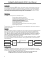
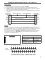
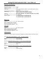
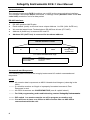
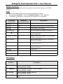
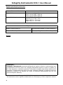
Integrity Instruments RCE-1 User Manual Integrity Instruments P.O. Box 451 Pine River Minnesota 56474 USA Order Phone Fax Phone Tech Phone 800-450-2001 218-587-3414 218-587-3120 http://www.integrityusa.com Remote Contact Extender RCE-1 RCE-1E(ENCLOSED) 1 Integrity Instruments RCE-1 User Manual Introduction The Integrity Instruments RCE-1 allows the user to monitor contact status at one location, and send these signals to a remote location. The system is bi-directional allowing contact status at the remote location to be sent back to the other end. Up to 8 inputs at each end can be sent as outputs to the other end. The uniqueness is that this is done over a single set of twisted pair wires using rs-485 communications. Applications The RCE-1 can be used for a multitude of uses. Remote alarm indication and reset. Contact control from a remote source. Physical status (loading doors open, pumps running). Production operational status. Manned operations acknowledgement. Remote physical positioning operations. Remote access control. Physical operations (open windows, start watering pumps) Remote lighting control. These are but a few, if there is a need for any remote operations, the remote contact extender is the answer. Operation The RCE-1 system consists of a master slave set. Power to each unit is supplied from the area it is at. When the units are powered a communication protocol is maintained between the units. Similar to a “watch dog” operation the units send information to each other. When an input is sensed at one end, this information is sent to the opposite end and a corresponding output is activated at the other end. If communication is lost, all outputs at both ends are de-activated. The communications between the units is done via rs-485. Normal baud rate is 115,200K. The rs-485 is capable of 4,000 foot distances. Using repeaters this can be increased almost indefinitely. up to 8 inputs Master up to 8 outputs Control Unit rs-485 twisted pair Slave up to 8 inputs Control Unit up to 8 outputs RS-485 Cabling The RCE-1 is designed to operate in a Multi-Drop RS-485 LAN configuration. In a halfduplex mullti-drop environment all RS-485 nodes share the same data lines. A single pair of data lines act as both Transmit and Receive wires. Data lines (A/B) are the only wires required between RS-485 nodes All RS-485 nodes need not share the same V+ and GND 2 Integrity Instruments RCE-1 User Manual Cabling Notes: 1) 2) 3) 4) Gnd and Shld are connected internally within the RCE-1 Cable termination is important for long distance and high-speed applications Suggested cable: 24 awg stranded twisted pair with shield for cable runs in excess of 200 feet. See also Belden cable #9841 and #9463. The end units (A) and (B) should be terminated. The RCE-1 has built in termination in the unit. DC power 7.5-24 Vdc Master RCE-1 terminal block Power supply ground Slave RCE-1 terminal block V+ V+ GND GND optional cable shield SHLD SHLD B B A A Physical The inputs and outputs are available through a female DB25 connector. The I/O lines are 5vdc operation. When + 5vdc is sensed at an input line, the corresponding output line goes high to + 5vdc. Voltage is present at the DB25 connector for external use. Performance Characteristics + Pwr Gnd Shld B sig A sig DB25 Connector This connector mates to our EXP-TRK or EXP-STA module allowing industry standard I/O modules to be used. Our DB25TSM unit is also available for easy terminal strip connections to the DB25 connector 13 12 11 10 9 DC input voltage 7.5 to 24 VDC DC input current 45 to 250 ma Baud Rate 115,200Kbps Termination resistance 120 ohms 7 8 6 5 4 3 2 1 DB25 Connector 25 24 23 22 21 20 19 18 17 16 15 14 Female front view - Male rear view 3 Integrity Instruments RCE-1 User Manual DB 25 connector inputs and outputs DB25 Description Master Slave 1 2 Port 2 bit 0 (PIC PORTD 0) Input Output Port 2 bit 1 (PIC PORTD 1) Output Input 3 Port 2 bit 2 (PIC PORTD 2) Input Output 4 Port 2 bit 3 (PIC PORTD 3) Output Input 5 Port 2 bit 4 (PIC PORTD 4) Input Output 6 Port 2 bit 5 (PIC PORTD 5) Output Input 7 Port 2 bit 6 (PIC PORTD 6) Input Output 8 Port 2 bit 7 (PIC PORTD 7) Output Input 9 DO NOT USE DO NOT USE DO NOT USE 10 No Connection N/A N/A 11 +V Unregulated Out N/A N/A 12 +5Vdc N/A N/A 13 GND N/A N/A 14 Port 1 bit 0 (PIC PORTB 0) Input Output 15 Port 1 bit 1 (PIC PORTB 1) Output Input 16 Port 1 bit 2 (PIC PORTB 2) Input Output 17 Port 1 bit 3 (PIC PORTB 3) Output Input 18 Port 1 bit 4 (PIC PORTB 4) Input Output 19 Port 1 bit 5 (PIC PORTB 5) Output Input 20 Port 1 bit 6 (PIC PORTB 6) Input Output 21 Port 1 bit 7 (PIC PORTB 7) Output Input 22 DO NOT USE DO NOT USE DO NOT USE 23 No Connection N/A N/A 24 +5Vdc N/A N/A 25 GND N/A N/A DIP Switch Settings 4 Position 1 Master control Position 3 Position 4 Baud N/A ON ON 115,200 N/A OFF ON 57,600 N/A ON OFF 19,200 ON N/A N/A Master run OFF N/A N/A Master idle/program Integrity Instruments RCE-1 User Manual Operation characteristics Firmware version --- -------------V2.5 Power on default --- -------------OFF Watchdog ------------ -------------If no communications within 1 second all outputs will be turned off. Communication protocol --------Master sends, slave responds Addressing ----------- -------------Master unit has odd numbered address Slave unit has even numbered address Initiation -- ------------ -------------Dip switch position 1 on master must be on to enable CPU clock ------------ -------------14.7456 Mhz Update speed ------- -------------10 milliseconds at 115,200 baud rate 11.5 milliseconds at 57,600 baud rate 18.4 milliseconds at 19,200 baud rate Master unit Address -- ------------ -------------01 Factory default Even numbered bits are inputs Odd numbered bits are outputs Async destination address -----02 Slave unit Address -- ------------ -------------02 Factory default Even numbered bits are outputs Odd numbered bits are inputs Async destination address -----N/A LED Operation Assume the system is wired, and power is applied to both the Master and Slave units. Idle (master DIP switch position 1 = OFF : no communication) Master ---- ------------ -------------Green blinking Slave ----- ------------ -------------Green blinking Running (master DIP switch position 1 = ON : communication good) Master ---- ------------ -------------Green/Red Slave ----- ------------ -------------Red Running (master DIP switch position 1 = ON : communication failure) Master ---- ------------ -------------Red Slave ----- ------------ -------------Green blinking 5 Integrity Instruments RCE-1 User Manual Communications The Integrity Instruments RCE-1 modules use rs-485 as the communications interface. The interface uses simple ASCII commands. A carriage return (decimal code 13 or Hex code 0x0D) marks the end of a data packet. RS-485 Interface: • • • • • RS-485 operates Half Duplex Each module (node) on the bus has a unique Address 1 to 254 (0x01-0xFE hex) We use the latest Linear Technologies RS-485 bus drivers (LTC1487) Address 0 (0x00 hex) is reserved for host PC. Address 255 (0xFF hex) is reserved for broadcast address. RS-485 Packet Format Destination Address xx Source Address xx Command/Response ASCII CR carriage return 13 (0x0D hex) x = ASCII Hexadecimal Digit Address 0x00 Address 0x01-0xFE Address 0xFF Reserved I/O Module Address Reserved Commands and Responses The following table illustrates the Integrity Instruments I/O module commands and responses. NOTE --------- All numeric data is represent as ASCII Hexadecimal integers (value x/y in the table) --------- If a module receives an illegal or improperly formatted command, Error Response is sent. --------- All ASCII characters are CASE SENSITIVE (use all capital letters!) --------- For field programming and troubleshooting contact Integrity Instruments. --------- DIP switch 1 on master must be set off to program or monitor unit. --------- You will have to have a rs-232 to rs-485 converter like our 485-25E to communicate with the unit. 6 Integrity Instruments RCE-1 User Manual Example Commands The following table illustrates actual command and response data for an RS-485 interface. NOTE All numeric data is represent as ASCII Hexadecimal integers • • • Example Host Address = 0x00 and Module Address = 0x01 (Master) The symbol ↵ equates to a carriage return (decimal 13, hex 0x0D) Command Sent by Host Response Sent by I/O Module Description 0001V↵ Vxy Firmware version x.y 0001K↵ Kxx Get receive error count (xx current count) 0001J↵ J Clear receive error count 0001Wyyxx↵ W Write EEPROM (yy address, xx value) 0001Ryy↵ Rxx Read EEPROM (yy address in command, xx value in reponse) S (master to slave) S Master sends Sxxyy (Master current inputs xx=Port 1 yy=Port 2 Slave reaction Slave updates with new Port 1 and Port 2 values from master S (slave to master) S Slave responds Sxxyy (Slave current inputs xx=Port s yy=Port 2 Master reaction Master updates with new Port 1 and Port 2 values from slave 0001Z↵ Z Reset CPU X Command error response EEPROM Map Address Description 0x00 MASTER Module Address (RS-485 address) [factory default = 0x01] 0x01 MASTER Async Destination Address, or slave address [factory default = 0x02] 0x00 SLAVE Module Address (RS-485 address) [factory default = 0x02] 0x01 SLAVE Async Destination Address, or slave address [N/A] 7 Integrity Instruments RCE-1 User Manual Digital Input/Output parameters Characteristic Value Digital I/O Current I/O line source & sink 25 ma Total current PORT1 200 ma Total current PORT2 200 ma Digital I/O Voltage Levels Input Off (0) = 0V - 0.8V Input On (1) = 2.0V - 5.0V Output Off (0) = 0.6V max. Output On (1) = 4.3V min. Digital I/O Levels Master or Slave Input Lo Corresponding Master or Slave Output Lo Master or Slave Input Hi Corresponding Master or Slave Output Hi NOTES WARRANTY Integrity Instruments warranties all products against defective workmanship and components for the life of the unit. Integrity Instruments agrees to repair or replace, at it’s sole discretion, a defective product if returned to Integrity Instruments with proof of purchase. Products that have been mis-used, improperly applied, or subject to adverse operating conditions fall beyond the realm of defective workmanship and are not convered by this warranty. Copyright © 2000-2003, Integrity Instruments All trademarks and/or registered trademarks are the property of their respective owners. 8