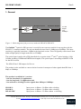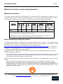
1
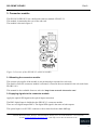
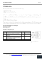
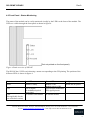
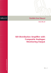
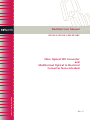
Flashlink User Manual
SDI-OE-S/SDI-OE-L/MF-OE-NRC
Fibre Optical SDI Converter
and
Multiformat Optical to Electrical
Converter Non-reclocked
network-electronics.com
Rev. 9
SDI-OE/MF-OE-NRC
Rev.9
Revision history
The latest version is always available in pdf-format on our web-site:
http://www.network-electronics.com/
Current revision of this document is the uppermost in the table below.
Revision Replaces
Date
Change Description
9
8
2007-10-29
New front page.
8
7
2007-09-07
Added Materials Declaration and EFUP; updated EC
Declaration of Conformity.
7
6
6
5
5
4
07.04.06 NBS Corrected LOS (LED) description in Chapter 4.2.
4
3
29.06.04 LEE Corrected specifications
3
2
02.12.03 AR Corrected GPI table.
2
1
18.08.03 RS
1
0
0
A
A
-
2007-02-16
NBS
2006-12-15
GMW
Updated GPI and LED information.
Changed maximum optical input power to -6 on SDIOE-L
Added improved NRC version, corrected bit rate
specification and input power range for SDI-versions
Removed NRC version, added –S and –L versions,
08.05.01 RS
new laser classification
15.12.00 NBS Renamed Optronics to Electronics & Rev. Control
25.06.00 RS Initial Revision
Network Electronics ASA, Thorøya, 3204 Sandefjord, Norway, Tel.:+47 33 48 99 99 Fax: +47 33 48 99 98
E-mail: [email protected] - Web: http://www.network-electronics.com
2
SDI-OE/MF-OE-NRC
Rev.9
Index
Revision history............................................................................................................................................2
1. General......................................................................................................................................................4
2. Specifications............................................................................................................................................5
3. Connector module....................................................................................................................................6
3.1 Mounting the connector module. .........................................................................................................6
3.2 Applying signals to the connector module...........................................................................................6
4. Module status ...........................................................................................................................................7
4.1 GPI – Module Status Outputs ..............................................................................................................7
4.2 Front Panel - Status Monitoring .........................................................................................................8
5. Laser safety precautions..........................................................................................................................9
General environmental requirements for flashlink® equipment ..........................................................10
Product Warranty .....................................................................................................................................11
Materials declaration and recycling information ...................................................................................12
Materials declaration ................................................................................................................................12
Environmentally-friendly use period.......................................................................................................12
Recycling information ...............................................................................................................................13
EC Declaration of Conformity .................................................................................................................14
Network Electronics ASA, Thorøya, 3204 Sandefjord, Norway, Tel.:+47 33 48 99 99 Fax: +47 33 48 99 98
E-mail: [email protected] - Web: http://www.network-electronics.com
3
SDI-OE/MF-OE-NRC
Rev.9
1. General
Optical Receiver
SDI Input Processor
Distribution Amplifier
Optical
Input
2 x SDI
Output
143540Mbps
Figure 1 : Block diagram of the processes inside the SDI-OE-S/SDI-OE-L
The flashlink ® Optical to SDI converter is a multi bit rate converter module for use together with the
SDI-OE-C1 connector module. The unit can handle bit rates from 19.4Mbps up to 540Mbps. The input
sensitivity is typically better than –30dBm in the long haul version. This will typically result in more than
60km of high quality of single mode fiber at 270Mbps.
The optical input is made with a PIN photodiode for reception in the 2nd and 3rd optical window (12001620nm including CWDM and DWDM wavelengths). The optical input is according to SMPTE-297M
for the SDI versions.
The SDI-OE has 2 SDI outputs for DA use.
The product is also available as a non-reclocked version for transport of other signals than SDI from 1
Mbps to 540Mbps.
The product is available in 3 versions:
- One for short haul (-S) applications,
- One for long haul (-L) applications and
- One without re-clocking for other signals than SDI up to 540Mbps:
SDI-OE-S
SDI-OE-L
MF-OE-NRC
Input power -6 dBm to –20 dBm with re-clocking
Input power -6 dBm to –30 dBm with re-clocking
Input power -6 dBm to –25 dBm without re-clocking
Network Electronics ASA, Thorøya, 3204 Sandefjord, Norway, Tel.:+47 33 48 99 99 Fax: +47 33 48 99 98
E-mail: [email protected] - Web: http://www.network-electronics.com
4
SDI-OE/MF-OE-NRC
Rev.9
2. Specifications
Optical Input, SDI version
Data rate optical:
19.4Mbps – 540Mbps
Sensitivity, SDI-OE-S:
Maximum input power, SDI-OE-S:
Detector overload threshold, SDI-OE-S:
Better than –20dBm
0 dBm
min. –6dBm, typ. –3dBm
Sensitivity, SDI-OE-L:
Maximum input power, SDI-OE-L:
Detector overload threshold, SDI-OE-L:
better than –30dBm
0 dBm
min. -6dBm, typ -3dBm
Optical wavelengths:
Transmission Circuit Fiber
Return loss (connector):
Connector
2nd & 3rd opt. windows, 1200-1620 nm
Multi Mode 50/125μm, Single Mode compatible
better than 40 dB w/Single Mode fiber (typ.)
SC/UPC
Optical Input, non-reclocked version
Data rate optical:
Sensitivity MF-OE-NRC:
Maximum input power MF-OE-NRC:
Optical wavelengths:
Transmission Circuit Fiber
Return loss (connector):
Detector overload threshold:
Connector
1Mbps – 540Mbps
better than –25dBm typ.
-6 dBm
2nd & 3rd opt. windows, 1200-1620 nm
Multi Mode 50/125μm, Single Mode compatible
better than 40 dB w/Single Mode fiber (typ.)
min. –6dBm, typ. –3dBm
SC/UPC
Electrical
Power:
Control:
+ 5V DC / 1.7W
Control system for access to set-up and module
status with BITE (Built-In Test Equipment).
SDI Output
Number of outputs:
Connector:
Impedance:
Return loss:
Signal level:
Rise/fall time:
Jitter (UI= Unit Interval):
2
BNC
75 ohm
> 15dB @270MHz
nom. 800mV
typ. 650ps
0.2 UI max.
Non-reclocked output
Number of outputs:
Connector:
Impedance:
2
BNC
75 ohm
Network Electronics ASA, Thorøya, 3204 Sandefjord, Norway, Tel.:+47 33 48 99 99 Fax: +47 33 48 99 98
E-mail: [email protected] - Web: http://www.network-electronics.com
5
SDI-OE/MF-OE-NRC
Rev.9
3. Connector module
The SDI-OE-S/SDI-OE-L has a dedicated connector module: SDI-OE-C1.
This module is mounted at the rear of the sub-rack.
The module is shown in figure 2.
Figure 2. Overview of the SDI-OE-C1 connector module
3.1 Mounting the connector module.
This section only applies if the module is not purchased pre-mounted in a sub-rack.
The details of how the connector module is mounted, is found in the user manual for the sub-rack frame
FR-2RU-10-2.
This manual is also available from our web site: http://www.network-electronics.com/
3.2 Applying signals to the connector module
Apply the optical SDI-signal to the optical input connection.
The BNC digital input is disabled at the SDI-OE-C1 connector module.
There are two digital output-BNCs. The digital SDI-signal is the same at both outputs.
The optical input is an SC/UPC connector with a return loss better than 40dB typ.
Network Electronics ASA, Thorøya, 3204 Sandefjord, Norway, Tel.:+47 33 48 99 99 Fax: +47 33 48 99 98
E-mail: [email protected] - Web: http://www.network-electronics.com
6
SDI-OE/MF-OE-NRC
Rev.9
4. Module status
The status of the module can be monitored in three ways.
1. Gyda-SC controller.
2. GPI at the rear of the sub-rack.
3. LED's at the front of the sub-rack.
Of these three, the GPI and the LED's are mounted on the module itself, whereas the Gyda-SC controller
is a separate module giving detailed information of the status of the card. The functions of the GPI and
the LED's are described in sections 4.1 and 4.2. The Gyda-SC controller is described in a separate user
manual.
4.1 GPI – Module Status Outputs
These outputs can be used for wiring up alarms for third party control systems. The GPI outputs are open
collector outputs, sinking to ground when an alarm is triggered. The GPI connector is shown in figure 2.
Electrical Maximums for GPI outputs
Max current: 100mA
Max voltage: 30V
SDI-OE-C1 GPI pin layout:
Signal
Status
LOS
LOCK
Ground
Name
General error status for the module.
Modulated optical input signal is
missing.
Re-clocker is in lock on a supported
signal format. (Not applicable for the
non-reclocked version)
0 volt pin
Pin # Mode
Pin 1 Open Collector
Pin 2 Open Collector
Pin 3 Open Collector
Pin 8 0V.
Figure 3: GPI Outlet
Network Electronics ASA, Thorøya, 3204 Sandefjord, Norway, Tel.:+47 33 48 99 99 Fax: +47 33 48 99 98
E-mail: [email protected] - Web: http://www.network-electronics.com
7
SDI-OE/MF-OE-NRC
Rev.9
4.2 Front Panel - Status Monitoring
The status of the module can be easily monitored visually by the LED's at the front of the module. The
LED's are visible through the front panel as shown in figure 4.
(Text not printed on the front panel).
Figure 4 Diode overview of SDI-OE
The SDI-OE has 3 LED's each showing a status corresponding to the GPI pinning. The position of the
different LED's is shown in figure 4.
Diode \ state
Status
Red LED
Module is faulty
LOS
Loss of signal
No modulated optical
input signal.
Re-clocker is not locked
Lock
(Not applicable for the
non-reclocked version)
Green LED
No light
Module is OK
Module has no power
Module power is OK
Optical input (modulated
SDI) signal present
Re-clocker locked
Network Electronics ASA, Thorøya, 3204 Sandefjord, Norway, Tel.:+47 33 48 99 99 Fax: +47 33 48 99 98
E-mail: [email protected] - Web: http://www.network-electronics.com
8
SDI-OE/MF-OE-NRC
Rev.9
5. Laser safety precautions
Guidelines to limit hazards from laser exposure.
All the available EO units in the flashlink® range include a laser.
Therefore this note on laser safety should be read thoroughly.
The lasers emit light at 1310 nm or 1550 nm. This means that the human eye cannot see the beam, and the
blink reflex can not protect the eye. (The human eye can see light between 400 nm to 700 nm).
A laser beam can be harmful to the human eye (depending on laser power and exposure time), therefore:
!!
BE CAREFUL WHEN CONNECTING / DISCONNECTING FIBER PIGTAILS (ENDS).
NEVER LOOK DIRECTLY INTO THE PIGTAIL OF THE LASER/FIBER.
NEVER USE MICROSCOPES, MAGNIFYING GLASSES OR EYE LOUPES TO LOOK INTO A
FIBER END.
USE LASER SAFETY GOGGLES BLOCKING LIGHT AT 1310 nm AND AT 1550 nm.
Instruments exist to verify light output power: Power meters, IR-cards etc.
Flashlink® features:
The FR-2RU-10-2 is classified as Class 1 laser product according to EN 60 825-1:94/A11:96, and
CFR Ch1(1997) Part 1040.10.
If the front panel is removed, the FR-2RU-10-2 is classified as Class 1 laser product according to
EN 60 825-1:94/A11:96, and class IIIb according to CFR Ch1(1997) Part 1040.10.
Maximum output power: 5 mW.
Operating wavelengths: 1310 nm or 1550 nm.
< 5mW
>1270nm
Network Electronics ASA, Thorøya, 3204 Sandefjord, Norway, Tel.:+47 33 48 99 99 Fax: +47 33 48 99 98
E-mail: [email protected] - Web: http://www.network-electronics.com
9
SDI-OE/MF-OE-NRC
Rev.9
General environmental requirements for flashlink® equipment
1. The equipment will meet the guaranteed performance specification under the following environmental
conditions:
•
•
Operating room temperature range
Operating relative humidity range
0°C to 50°C
up to 90% (non-condensing)
2. The equipment will operate without damage under the following environmental conditions:
•
•
Temperature range
Relative humidity range
-10°C to 55°C
up to 95% (non-condensing)
Network Electronics ASA, Thorøya, 3204 Sandefjord, Norway, Tel.:+47 33 48 99 99 Fax: +47 33 48 99 98
E-mail: [email protected] - Web: http://www.network-electronics.com
10
SDI-OE/MF-OE-NRC
Rev.9
Product Warranty
The warranty terms and conditions for the product(s) covered by this manual follow the General Sales
Conditions by Network Electronics ASA. These conditions are available on the company web site of
Network Electronics ASA:
www.network-electronics.com
Network Electronics ASA, Thorøya, 3204 Sandefjord, Norway, Tel.:+47 33 48 99 99 Fax: +47 33 48 99 98
E-mail: [email protected] - Web: http://www.network-electronics.com
11
SDI-OE/MF-OE-NRC
Rev.9
Materials declaration and recycling information
Materials declaration
For product sold into China after 1st March 2007, we comply with the “Administrative Measure on the
Control of Pollution by Electronic Information Products”. In the first stage of this legislation, content of
six hazardous materials has to be declared. The table below shows the required information.
Toxic or hazardous substances and elements
組成名稱
Part Name
SDI-OE
鉛
汞
镉
六价铬
多溴联苯
多溴二苯醚
Lead Mercury Cadmium Hexavalent Polybrominated Polybrominated
(Pb)
(Hg)
(Cd)
Chromium
biphenyls
diphenyl ethers
(Cr(VI))
(PBB)
(PBDE)
X
O
O
O
O
O
O: Indicates that this toxic or hazardous substance contained in all of the homogeneous materials for
this part is below the limit requirement in SJ/T11363-2006.
X: Indicates that this toxic or hazardous substance contained in at least one of the homogeneous
materials used for this part is above the limit requirement in SJ/T11363-2006.
Environmentally-friendly use period
The manual must include a statement of the “environmentally friendly use period”. This is defined as the
period of normal use before any hazardous material is released to the environment. The guidance on how
the EFUP is to be calculated is not finalised at the time of writing. See
http://www.aeanet.org/GovernmentAffairs/qfLeOpAaZXaMxqGjSFbEidSdPNtpT.pdf for an unofficial
translation of the draft guidance. For our own products, Network Electronics has chosen to use the 50
year figure recommended in this draft regulation.
Network Electronics suggests the following statement on An “Environmentally Friendly Use Period”
(EFUP) setting out normal use:
EFUP is the time the product can be used in normal service life without leaking the hazardous materials. We expect the normal
use environment to be in an equipment room at controlled temperature range (0ºC - 40ºC) with moderate humidity (< 90%,
non-condensing) and clean air, not subject to vibration or shock.
Further, a statement on any hazardous material content, for instance, for a product that uses some tin/lead
solders:
Where a product contains potentially hazardous materials, this is indicated on the product by the appropriate symbol
containing the EFUP. The hazardous material content is limited to lead (Pb) in some solders. This is extremely stable in
normal use and the EFUP is taken as 50 years, by comparison with the EFUP given for Digital Exchange/Switching Platform in
equipment in Appendix A of “General Rule of Environment-Friendly Use Period of Electronic Information Products”. This is
indicated by the product marking:
50
Network Electronics ASA, Thorøya, 3204 Sandefjord, Norway, Tel.:+47 33 48 99 99 Fax: +47 33 48 99 98
E-mail: [email protected] - Web: http://www.network-electronics.com
12
SDI-OE/MF-OE-NRC
Rev.9
It is assumed that while the product is in normal use, any batteries associated with real-time clocks or battery-backed RAM will
be replaced at the regular intervals.
The EFUP relates only to the environmental impact of the product in normal use, it does not imply that the product will
continue to be supported for 50 years.
Recycling information
Network Electronics provides assistance to customers and recyclers through our web site
http://www.network-electronics.com. Please contact Network Electronics’ Customer Support for
assistance with recycling if this site does not show the information you require.
Where it is not possible to return the product to Network Electronics or its agents for recycling, the
following general information may be of assistance:
Before attempting disassembly, ensure the product is completely disconnected from power and signal
connections.
All major parts are marked or labelled to show their material content.
Depending on the date of manufacture, this product may contain lead in solder.
Some circuit boards may contain battery-backed memory devices.
Network Electronics ASA, Thorøya, 3204 Sandefjord, Norway, Tel.:+47 33 48 99 99 Fax: +47 33 48 99 98
E-mail: [email protected] - Web: http://www.network-electronics.com
13
SDI-OE/MF-OE-NRC
Rev.9
EC Declaration of Conformity
MANUFACTURER
Network Electronics ASA
P.B. 1020, N-3204 SANDEFJORD, Norway
AUTHORISED REPRESENTATIVE
(Established within the EEA)
Not applicable
MODEL NUMBER(S)
SDI-OE
DESCRIPTION
Fiber Optical SDI Converter and Mulitformat Optical to
Electrical Converter Non-reclocked
DIRECTIVES this equipment complies with
LVD 73/23/EEC
EMC 89/336/EEC
HARMONISED STANDARDS applied in order to
verify compliance with Directive(s)
EN 55103-1:1996
EN 55103-2:1996
EN 60950-1:2006
TEST REPORTS ISSUED BY
Notified/Competent Body
Report no:
Nemko
200013115
TECHNICAL CONSTRUCTION FILE NO
Not applicable
YEAR WHICH THE CE-MARK WAS AFFIXED
2000
TEST AUTHORIZED SIGNATORY
MANUFACTURER
AUTHORISED REPRESENTATIVE
(Established within EEA)
Date of Issue
2007-09-07
Place of Issue
Not applicable
Name
Thomas Øhrbom
Position
Quality Manager
(authorised signature)
Sandefjord, Norway
Network Electronics ASA, Thorøya, 3204 Sandefjord, Norway, Tel.:+47 33 48 99 99 Fax: +47 33 48 99 98
E-mail: [email protected] - Web: http://www.network-electronics.com
14