1
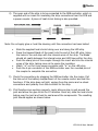
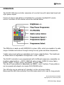
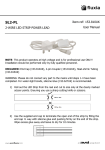
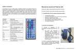
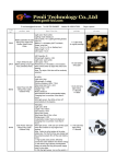
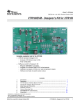
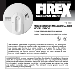
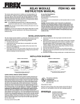
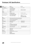
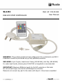
SL4-RC RGB LED STRIP CONTROLLER Item ref: 153.811UK User Manual WARNING: This product operates at high voltage and is for professional use ONLY! Installation should be performed only by fully qualified personnel. INCLUDED: 4-pin Coupler, Heat-shrink Tubing (153.815UK), End Cap (153.819UK) For water-tight bonds, silicone glue (153.627UK not supplied) is recommended. IMPORTANT: Maximum RGB strip length for SL4-RC controller is 25m total. Do not connect longer runs as this will damage the controller. Please do not connect any part to the mains until steps 1-4 have been completed. ASSEMBLY 1) Roll out the LED Strip from the reel and cut to size only at the clearly marked scissor points. Ensuring you use a sharp cutting knife or scissors. (Max. 25m) 2) Use the supplied end cap to terminate the open end of the strip by filling the end cap ½ way with silicone glue and pushing firmly on the end of the strip. Wipe excess glue away and leave to dry for 10 minutes. 3) If the strip is to be extended onto another strip or fitted around tight corners, it will be necessary to use a strip coupler (153.817UK) or flexible link (153.818UK). For either of these options, create the connection in the same manner as described below for the RGB controller connection. 153.811UK User Manual 4) The open end of the strip is to be connected to the RGB controller, which is supplied with an insert for insulating the strip connections from the PCB and a power coupler. A piece of heat shrink tubing is also provided. Note: Do not apply glue or heat the sleeving until the connection has been tested Slide the supplied heat shrink tubing over and along the LED strip Press the tapered blade of the insert into the end of the LED strip, lining the holes in the end-stop with the internal wires of the strip. The blade should sit neatly between the internal wires and LED tape within the strip Push the sharp pins of the coupler through the insert and into the internal wires of the strip, taking care not to pierce the insulation Match “+” on the 4-pin power connector with “+” on the LED strip Push the 4-pin connector of the RGB controller over the rounded pins of the coupler to complete the connection 5) Check the connections by plugging the RGB controller into the mains. Pull the tab out of the battery compartment of the remote control and test the functions. If the strip does not light, unplug from the mains and re-check connections and polarity from the controller to the strip. 6) If all functions are working properly, apply silicone glue in and around the joint and allow the glue to set for 10 minutes. Once set, slide the heat shrink tubing over the joint and heat to seal around the components. The resulting joint should appear as shown below. 153.811UK User Manual OPERATION The SL4-RC LED strip controller comprises of a control box with mains lead input and 4-pin power output. Control of colours and patterns is facilitated by a wireless handheld RF remote control. Functions of this remote control are outlined below. The RGB strip is made up with SMD5050 tri-colour LEDs, which are capable of a wide range of shades and colours through mixing the red, green and blue components. 7 static colours and white are selectable via 8 colour-coded buttons. The brightness of these colours is adjustable via brightness + and – buttons. The SL4-RC controller is pre-programmed with 6 different sequences, accessible via 6 pattern select buttons – AUTO, JUMP3 (3 colour jump), FADE3 (3 colour fade), FLASH, JUMP7 (7 colour jump), and FADE7 (7 colour fade), The rate of these patterns is adjustable via SPEED + and – buttons. These patterns can be paused and played via a single PLAY/PAUSE button. The LED strip can be switched off (standby) via the red power button. Disconnect the LED strip controller from the mains when not in use for long periods. Errors and omissions excepted. Copyright© 2013. AVSL Group Ltd. 153.811UK User Manual