1
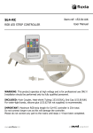
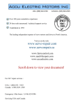
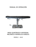
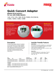
RELAY MODULE
INSTRUCTION MANUAL
ITEM NO. 499
This manual contains instructions for installing your Firex Relay Module. This
relay module is U.L. listed as an accessory for use only with the Firex Smoke
Alarm Nos. 406 (G-6), 418 (G-18), 420 (G-120), 4418 (AD), 4480 (PAD), 4518 (ADC),
4580 (FPAD), 5000, 4618, 46182 (FADC), 5700 (ADH), 7000 (FADCQ) and is used to
activate auxiliary devices. All auxiliary devices to be activated shall be 120 Volt
60Hz 5 Amps maximum, or 28 VDC 5 Amps maximum.
Use your Firex Relay Module for:
Sirens/Exit Signs/Bells
Warning Lights/Fire Doors/Exhaust Fans
Visual Indicators
NOTE: On the 7000 (FADCQ) Smoke/CO Combo , the 499 relay module will
respond to the smoke alarm only. It will not respond to the CO alarm.
CAUTION: THE RELAY MODULE IS NOT TO BE USED AS A METHOD OF
EXTENDING THE MAXIMUM NUMBER OF SMOKE ALARMS PERMITTED IN
MULTIPLE STATION OPERATION. (REFER TO SMOKE ALARM MANUAL FOR
SPECIFIED MAXIMUM LIMIT.) EACH RELAY MODULE REPLACES ONE SMOKE
ALARM LOAD IN AN INTERCONNECTED STRING. THEREFORE, USE OF THE
RELAY REDUCES THE MAXIMUM NUMBER OF INTERCONNECTED SMOKE
ALARMS BY ONE.
WARNING: This relay will not operate without continuous AC power. Do not use
with battery backup units.
CAUTION: Do not interconnect Model No. 499 to Models COQ8, FXW-1A, FX1014,
FX1020, FX1106 or any other manufacturer's units. Doing so will permanently
damage the relay.
The relay module is not recommended for use with automatic dialers or security
alarm panels.
INSTALLATION INSTRUCTIONS
The relay module should be installed in a junction box. All connections should be
made by a qualified electrician in accordance with the requirements of the
National Electric Code and/or any local codes having jurisdiction.
1. Turn off main power circuit.
2. Install and wire your Firex smoke alarm as recommended in your smoke
alarm owner's manual.
3. Connect the black wires of the relay module and the smoke alarm to the
black wire of the 12OVAC line.
4. Connect the yellow wire of the relay module to the yellow wire of the smoke
alarm. NOTE: Connection of yellow wire to any voltage source greater than
20 volts will damage unit and void warranty.
5.
Connect the white wire of the relay module to the white wire of the
smoke alarm.
6. Connect the auxiliary device to the relay module contact leads as required.
Both normally open and normally closed contacts are available to control
the auxiliary device. NOTE: The relay contact rating is 5 Amps max. @
12OVAC or 28 VDC. See NEC, Article 725-52 for additional information on
combining 12OVAC circuits with low voltage Class 2 and Class 3 circuits.
7. Cap any unused leads with a wire nut.
8. Insert the relay module into the junction box and install the faceplate.
9. Apply power to the circuit and test the smoke alarm and the auxiliary device
for proper operation.
10. See below for examples of wiring normally open or normally closed circuits.
INSTALLATION DIAGRAMS
CLIMATE CONTROLS AMERICAS LIMITED WARRANTY
Climate Controls Americas warrants to the original consumer purchaser each
new Firex® relay module to be free from defects in material and workmanship
under normal use and service for a period of one (1) year from date of purchase.
Climate Controls Americas agrees to repair or replace, at its option, any Firex®
relay module found defective provided that it is returned with postage prepaid
and with proof of purchase date to Climate Controls Americas. This warranty
does not cover any battery which may be used in the product, or any damage
resulting there from, nor does the warranty cover damage resulting from accident, misuse or abuse or lack of reasonable care of the product. This warranty is
in lieu of all other express warranties, obligations, or liabilities. THE IMPLIED
WARRANTIES OF MERCHANTABILITY AND FITNESS FOR A PARTICULAR PURPOSE ARE LIMITED TO A PERIOD OF ONE (1) YEAR FROM PURCHASE DATE.
Some states do not allow limitation on how long an implied warranty lasts, so the
above limitation may not apply to you. In no case shall Climate Controls Americas
be liable for any consequential damages for breach of this or any other warranty,
express or implied, whatsoever. Some states do not allow the exclusion of consequential damages, so the above exclusion may not apply to you. This warranty
gives you specific legal rights, and you may also have other legal rights which
vary from state to state.
© Invensys Controls Americas 2005
This product is listed by
UNDERWRITERS
LABORATORIES, INC. and
bears the mark.
Instructions for return:
State the trouble and place the relay module and proof of date of
purchase in a well padded carton and return postage prepaid to:
Controls Americas
Product Service Department
28C Leigh Fisher Blvd.
El Paso, TX 79906
United States of America
111-329
ITEM NO. 499
MODULO DE RELE
MANUAL DE INSTRUCCIONES
Este manual contiene las instrucciones para la instalación del módulo de relé
Firex. Este módulo de relé está en la lista de U.L. como un accesorio para uso
solamente con las alarmas de humo Firex Nos. 406 (G-6), 418 (G-18), 420 (G-120),
4418 (AD), 4480 (PAD), 4518 (ADC), 4580 (FPAD), 5000, 4618, 46182 (FADC), 5700
(ADH), 7000 (FADCQ) y se usa para activar los dispositivos auxiliares. Todos los
dispositivos auxiliares tienen que ser de 120 Volt 60Hz 5 amps máximo o 28 VCC 5
amps máximo para ser activados.
NOTA: En 7000 (FADQC) combinación del CO del humo, el módulo 499 relay responderá al
alarmar del humo solamente. No responderá al alarmar del CO.
ADVERTENCIA: Este relé no operará con corriente CA continua. No lo use con
unidades de repuesto con batería.
PRECAUCION: No interconecte el Modelo No. 499 con los Modelos COQ8, FXW1A, FX1O14, FX1O2O, FX1106 o con alguna otra unidad de otros fabricantes. De lo
contrario el relé sufrirá daño permanente.
Use su módulo de relé Firex para:
Sirenas/ señales de salida/ timbres/ luces de advertencia/ puertas de incendio/
ventiladores de escape/ indicadores visuales.
No se recomienda usar el módulo de relé con marcadores automáticos o con
paneles de alarma de seguridad.
PRECAUCION: EL MODULO DE RELE NO SE DEBE USAR COMO UN METODO
PARA EXTENDER EL NUMERO MAXIMO DE ALARMAS DE HUMO PERMITIDAS
EN UNA OPERACION DE ESTACION MULTIPLE. (REFIERASE AL MANUAL DE LA
ALARMA DE HUMO PARA UN LIMITE MAXIMO ESPECIFICADO.) CADA MODULO
DE RELE REEMPLAZA UNA CARGA DE DETECCION DE HUMO EN UNA SERIE
INTERCONECTADA. POR LO TANTO EL USO DEL RELE REDUCE EL NUMERO
MAXIMO DE DETECTORES DE HUMO INTERCONECTADOS EN UNO.
INSTRUCCIONES PARA LA INSTALACION
El módulo de relé tiene que instalarse en una caja de conexiones. Todas as
conexiones tienen que ser hechas por un electricista calificado según los
requisitos del Código Eléctrico Nacional y/o según cualquier código local que
tenga jurisdicción.
1. Apague la electricidad principal que va al circuito.
2. Instale y cablee su alarma de humo Firex tal como se recomienda en su
manual para el dueño de la alarma de humo.
3. Conecte los cables negros del módulo de relé y el detector de humo con el
cable negro de la línea de 120 VCA.
4. Conecte el cable amarillo del módulo de relé con el cable amarillo del
detector de humo. AVISO: La conexión del cable amarillo con cualquier
fuente de voltaje mayor de 20 volts dañará a unidad y anulará la garantía.
5. Conecte el cable blanco con el módulo de relé al cable blanco del detector
de humo.
6.
Conecte el dispositivo auxiliar con los conductores de contacto del módulo
de relé. Tanto el contacto que está normalmente abierto como el que está
normalmente cerrado están disponibles para controlar el dispositivo
auxiliar. AVISO: La capacidad del contacto de relé es de 5 amps máximo a
120 VCA 0 28 VCC. Vea el artículo NEC. 725-52 para más información para la
combinación de circuitos 120 VCA con voltaje bajo de circuitos clase 2 y
clase 3.
7. Termine los conductores no usados con una tuerca para cable.
8. Inserte el módulo de relé en la caja de conexiones e instale la placa delantera.
9. Aplique la corriente al circuito y pruebe el detector de humo y el dispositivo
auxiliar para verificar si la operación es adecuada.
10. Vea los ejemplos a continuación para cablear circuitos normalmente
abiertos o normalmente cerrados.
DIAGRAMAS DE INSTALACION
GARANTIA LIMITADA DE CLIMATE CONTROLS AMERICAS
Climate Controls Americas garantiza al comprador original que el módulo de relé
Firex® no tendrá defectos ni en los materiales ni en la mano de obra por un (1)
año de servicio de uso normal a partir de la fecha de compra. Climate Controls
Americas se compromete a reparar o cambiar, a su discreción, cualquier módulo
de relé Firex® que se encuentre defectuoso siempre y cuando se devuelva a
Climate Controls Americas con el franqueo prepagado y con la prueba de la
fecha de compra. Esta garantIa no cubre ninguna bateria que se use en el producto y cualquier daño resultante ni tampoco cubre daños producidos por accidentes, ma) uso o abuso o por falta del cuidado razonable del producto. Esta
garantla se ofrece en lugar de todas las demés garantIas expresas, obligaciones
o responsabilidades. LAS GARANTIAS IMPLICITAS DE COMERCIALIZACION 0 DE
ADECUACION PARA CUALQUIER USO EN PARTICULAR QUEDAN LIMITADAS AL
PERIODO DE UN (1) ANO A PARTIR DE LA FECHA DE COMPRA. Algunos estados
no permiten limitaciones en cuanto al perIodo de tiempo que una garantIa puede
durar, asi que puede ser que las limitaciones anteriores no se apliquen en su
caso. Por ningún motivo Climate Controls Americas será responsable por ningún
daño emergente debido al incumplimiento de ésta o de ninguna otra garantla,
expresa o implIcita. Algunos estados no permiten la exclusión de los daños
emergentes asI que la exclusión anterior puede ser que no se aplique en su
caso. Esta garantla le otorga derechos legales especIficos y también puede
tener otros derechos legales que pueden variar de un estado a otro.
Este producto aparece en la lista de
UNDERWRITERS
LABORATORIES, INC. y
lleva la marca.
Instrucciones para la devolución:
Indique el problema y ponga el módulo de reléen un cartón bien
acojinado y devuélvalo con el franqueo prepagado a:
Controls Americas
Product Service Department
28C Leigh Fisher Blvd.
El Paso, TX 79906
United States of America
111-329