1
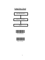
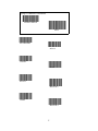
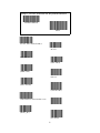
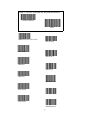
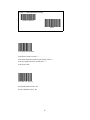
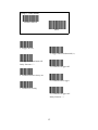
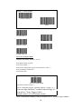
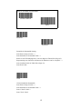
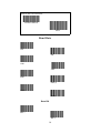
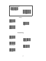
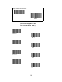
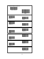
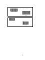
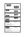
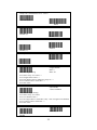
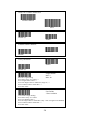
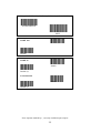
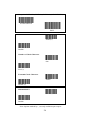
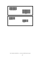
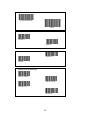
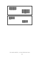
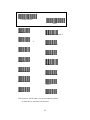
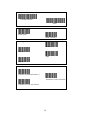
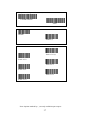
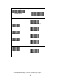
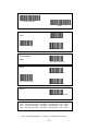
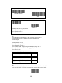
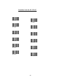
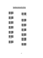
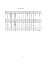
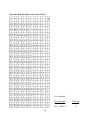
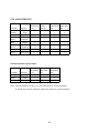
1
CONTENTS
Getting Started ----------------------------------------------------------- 2
Setup Procedures -------------------------------------------------------- 3
Setup Menu----------------------------------------------------------------4
Setup flow Chart ---------------------------------------------------------4
Group 0 : Interface Selection ----------------------------------------- 5
Group 1 : Device Selection for keyboard interface-----------------6-7
Group 2 : Inter-character Delay -------------------------------------- 8
Group 3 : Language for Keyboard Interface ------------------------9-10
Group 4 : Terminator---------------------------------------------------11-12
Group 5 : Scan Mode -------------------------------------------------- 13-14
Group 6 : Preamble and Postamble ----------------------------------15
Group 7 : Reserved ----------------------------------------------------15
Group 8 : RS-232 Parameters ---------------------------------------- 16-18
Group 9 : Code 39 / Code 32 ----------------------------------------- 19-20
Group 10-1: Interleaved 2 of 5 -----------------------------------------21
Group 10-2: Industrial 2 of 5 / IATA----------------------------------22
Group 10-3: Matrix 2 of 5-----------------------------------------------23
Group 10-4: China Postage--------------------------------------------- 24
Group 11 : Code 128/ Code 93/ Code 11/ MSI-PLESSEY-------- 25-26
Group 12 : ISBN/ISSN------------------------------------------------- 27
Group 13 : Codabar / NW7---------------------------------------------28
Group 14 : Code 4------------------------------------------------------- 29
Group 15-1 : EAN 13 / JAN 13---------------------------------------- 30
Group 15-2 : UPC-A-----------------------------------------------------31
Group 15-3 : EAN-8 / JAN-8-------------------------------------------32
Group 15-4 : UPC-E / UCC EAN-128-------------------------------- 33
Group 16 : General Parameters---------------------------------------- 34
Group 17 : Code ID Settings-------------------------------------------35
Group 18 : Wand Type Parameters----------------------------------- 36
Group 19 : Magnetic Parameters-------------------------------------- 37-39
Group 20 : Function Key Emulation----------------------------------40
Function Code for PC XT/AT-----------------------------------------------41-42
Table-Hex : Hexadecimal----------------------------------------------------43
ASCII Table--------------------------------------------------------------------44
Hexadecimal-Decimal Conversion Table ---------------------------------45
Pin Assignments of Scanners------------------------------------------------46-47
1
Getting Started
Installing Keyboard Wedge Scanner
To install a keyboard wedge scanner, follow the steps listed below:
1) Make sure that the scanner has the correct Y (U)- cable for the system (a PC or terminal)
2) Turn off the power of the system
3) Unplug the keyboard from the system
4) Connect the Y (U)- cable to the system and keyboard
5) Turn on the power of the system
6) If the indicator LED lights up and the buzzer sounds, the scanner is ready for reading
Installing a RS-232 Interface Scanner
To install a RS-232 interface scanner, the host device should have a RS-232 port to
receive data from the scanner, follow the steps listed below:
1) Make sure that the scanner has the right connector for the RS-232 port of the host device
2) Make sure that there is a power supply to the scanner (if necessary)
3) Connect the cable to the RS-232 port of the device
4) If the indicator LED lights up and the buzzer sounds, the scanner is ready for reading
2
Setup Procedures
1) Locate a group that contains the parameters to be changed.
2) Scan the “Enter Group #” label. The scanner will sound beeps indicate that setup is in progress
3) Scan the label representing the parameter to be changed
4) Scan the “Exit” to end the group currently selected, the scanner will sound beeps.
5) Repeat the procedure for other groups including the parameters to be changed
Example 1:
Set the operating mode to “Continuous mode”
1) Scan “Enter Group 5”
2) Scan “Continuous/Trigger off”
3) Scan “Exit”
Example 2
Assign Preamble string as “#”, and postamble string as “END”
1) Scan “Enter Group 6”
2) Scan Preamble”
3) Scan “#” from “Full ASCII Table and Table-Hex.”
4) Scan “Confirm” Label in Table-Hex
5) Scan “Postamble”
6) Scan “E”, “N”, “D” from “Full ASCII Table and Table Hex” consecutively
7) Scan “Confirm” Label in Table-Hex.
8) Scan Exit
3
Setup Flow Chart
ENTER GROUP
SELECT ITEMS
EXIT
Set All Defaults
Show Version
4
Group 0: Interface Selection
ENTER GROUP
EXIT
KEYBOARD
RS-232
WAND
OCIA
RS-232
Reserved 2
DTMF
Reserved 4
5
Group 1: Device Selection for Keyboard Interface
ENTER GROUP
EXIT
PC/AT, PS/2 50,60,70,80(*)
PC/XT
PS/2 25, 30
(NEC 9801)
(IBM 5550)
(PS 55)
(NEC N5520)
(ACER 7300)
(KW1050D/CT-700A/WANG 5120)
(WANG 5425)
(MAC_SE)
(LC-6533)
6
Group 1: Device Selection for Keyboard Interface
ENTER GROUP
EXIT
(IBM3196,3197,3476,3477)
Reserved Q
Reserved R
Reserved T
IBM3197
IBM 3476
IBM3477
RESERVED 5
Reserved 6
RESERVED 7
Reserved 8
RESERVED 9
7
Group 2: Intercharacter Delay
ENTER GROUP
EXIT
Start Keyboard Setting
Scan Enter Group 2 Label -- >
Scan Start Keyboard (or RS-232) Setting Label -->
Scan two digits labels in "Table-Hex" -->
Scan Exit Label
Start RS-232 Setting
Keyboard Default Value: 05
RS-232 Default Value : 00
8
Group 3: Language for Keyboard Interface
ENTER GROUP
EXIT
U.S. (*)
ENGLAND
FRANCE
GERMANY
ITALY
BELGIUM
SWEDEN/FINLAND
SPANISH
DENMARK
PORTUGAL
SWISS
NORWAY
9
Group 3: Language for Keyboard Interface
ENTER GROUP
EXIT
CANADA
HOLLAND
POLAND
LATIN
JAPAN
RESERVED 1
RESERVED 2
RESERVED 3
(IBM THINK-PAD FOR JAPAN)
(PANASONIC CF-II FOR JAPAN)
10
Group 4: Terminator
ENTER GROUP
EXIT
KEYBOARD
NONE
CR
SPACE
TAB
ESC
CTRL-C
ESC
11
Group 4: Terminator
ENTER GROUP
EXIT
RS-232
NONE
CR
CR/LF
LF
SPACE
TAB
ESC
CTRL-C
STX..ETX
XON.. XOFF
EOT
12
Group 5: Scan Mode
ENTER GROUP
EXIT
1: Trigger On/Off
2: Trigger On/Good Read Off (*)
3: Trigger On/Good Read Off/
Delay Timeout = ?
4: Continuous/Trigger Off
5: Continuous/LED Always on
6: Continuous/No Trigger
7: Continuous/Testing
8: Continuous/Trigger Off/
Delay Timeout = ?
13
Group 5: Scan Mode
ENTER GROUP
EXIT
FLASH OFF(*)
FLASH ON
SHORT ZONE
LONG ZONE
LASER DELAY
For Laser Scanner Mode
Default Laser Delay Timeout = 60 sec.
Scan Enter Group 5 Label
Scan Laser Delay -->
Refer to the Table-Hex at page 41 and select a value -->
Scan Confirm in Table Hex.
Scan Exit Label
LAG-960TR - Auto Trigger mode
AUTO TRIGGER
Scan Enter Group 5 Label -->
Scan 8: Continuous/Trigger off/Delay timeout=? (Page 13) -->
Scan two digit label and "confirm" label in Page 43 -->
Scan Above "Auto Trigger Label)
Switch on the LAG-960 bottom switch
Note: Scan mode setting is only available for CCD/Laser type scanner.
14
Group 6: Preamble and Postamble
ENTER GROUP
EXIT
Preamble
Postamble
Preamble & Postamble Setting:
Scan Enter Group 6 Label -->
Scan Preamble or Postamble Label -->
Refer to ASCII Table(page 44), scan two digits in Table-Hex (Page 43)
Representing one character, maximum 10 characters can be accepted. -->
Scan Confirm Label in Table-Hex (Page 43)
Scan Exit Label
Clear
Clear Preamble & Postamble :
Scan Enter Group 6 Label -->
Scan Preamble or Postamble Label -->
Scan "Clear" Label-->
Scan "Exit" Label
15
Group 8: RS-232 Parameters
ENTER GROUP
EXIT
Baud Rate
300
600
1200
2400
4800
9600(*)
19200
38400
Data Bit
BIT 7
BIT 8
16
Group 8: RS-232 Parameters
ENTER GROUP
EXIT
Parity :
NONE (*)
ODD
EVEN
Handshaking:
NONE (*)
XON/OFF
Scanner Ready
Data Ready
ACK/NAK
17
Group 8: RS-232 Parameters
ENTER GROUP
EXIT
(CK/NAK Response Time
CTS Observation Time:)
100 ms
300 ms
500 ms
1 sec.
3 sec (*)
5 sec.
10 sec.
00
18
Group 9: CODE 39 / (CODE 32)
ENTER GROUP
EXIT
Enable (*)
Disable
Standard (*)
Full ASCII
Transmit Start/End Character
Disable (*)
Enable
Transmit Check Character
Enable (*)
Disable
Verify Checksum
Enable
Disable (*)
Enable CODE 32
19
Group 9: CODE 39 / (CODE 32)
ENTER GROUP
EXIT
Verify Normal (*)
Verify Strick
20
Group 10-1: Interleaved 2 OF 5
ENTER GROUP
EXIT
Disable (*)
Enable
Transmit Check Character
Disable
Enable (*)
Verify Checksum
Disable
Enable
Length Define
Barcode Length Setting
Min: 4
Max: 48
Scan Enter Group 10-1 Label -->
Scan Length Define Label -->
Scan Four Digit Labels in Table Hex (Page 43) -->
Scan Confirm Label in Table-Hex -->
Scan Exit Label
User Define
3 Sets Available
User Define Length Setting:
Scan Enter Group 10-1 Label
Scan User Define Label-->
Scan Six Digit Labels in Table Hex (Only 3 sets of length can be defined)
Scan Confirm Label in Table Hex -->
Scan Exit Label
21
Group 10-2: Industrial 2 OF 5 / IATA
ENTER GROUP
EXIT
Disable (*)
Enable
Transmit Check Character
Disable
Enable (*)
Verify Checksum
Disable
Enable
Length Define
Barcode Length Setting
Min: 2
Max: 24
Scan Enter Group 10-2 Label -->
Scan Length Define Label -->
Scan Four Digit Labels in Table Hex (Page 43) -->
Scan Confirm Label in Table-Hex -->
Scan Exit Label
User Define
3 Sets Available
User Define Length Setting:
Scan Enter Group 10-2 Label
Scan User Define Label-->
Scan Six Digit Labels in Table Hex (Only 3 sets of length can be defined)
Scan Confirm Label in Table Hex -->
Scan Exit Label
Disable (*)
Enable
22
Group 10-3: Matrix 2 of 5
ENTER GROUP
EXIT
Disable (*)
Enable
Transmit Check Character
Enable (*)
Disable
Verify Checksum
Enable
Disable (*)
Length Define
Min: 2
Barcode Length Setting
Max: 40
Scan Enter Group 10-3 Label -->
Scan Length Define Label -->
Scan Four Digit Labels in Table Hex (Page 43) -->
Scan Confirm Label in Table-Hex -->
Scan Exit Label
User Define
3 Sets Available
User Define Length Setting:
Scan Enter Group 10-3 Label
Scan User Define Label-->
Scan Six Digit Labels in Table Hex (Only 3 sets of length can be defined)
Scan Confirm Label in Table Hex -->
Scan Exit Label
23
Group 10-4: CHINA POSTAGE
ENTER GROUP
EXIT
Disable (*)
Enable
Transmit Check Character
Enable (*)
Disable
Verify Checksum
Enable
Disable (*)
Length Define
Min: 2
Barcode Length Setting
Max: 40
Scan Enter Group 10-3 Label -->
Scan Length Define Label -->
Scan Four Digit Labels in Table Hex (Page 43) -->
Scan Confirm Label in Table-Hex -->
Scan Exit Label
User Define
3 Sets Available
User Define Length Setting:
Scan Enter Group 10-3 Label
Scan User Define Label-->
Scan Six Digit Labels in Table Hex (Only 3 sets of length can be defined)
Scan Confirm Label in Table Hex -->
Scan Exit Label
24
Group 11: CODE 128/(CODE 93)/(CODE 11)/(MSI-PLESSEY)
ENTER GROUP
EXIT
CODE 128
Enable (*)
Disable
CODE 93
Enable
Disable (*)
Concatenation
Enable
Disable (*)
Note: Options marked by ( ) are only available upon request
25
Group 11: CODE 128/(CODE 93)/(CODE 11)/(MSI-PLESSEY)
ENTER GROUP
EXIT
Enable(*)
Disable
Number of Check Character
One
Two (*)
Transmit Check Character
Enable
Disable (*)
MSI/PLESSEY
Enable (*)
Disable
Note: Options marked by ( ) are only available upon request
26
Group 12: (ISBN/ISSN)
ENTER GROUP
EXIT
Disable (*)
Enable
Note: Options marked by ( ) are only available upon request
27
Group 13: CODABAR / NW7
ENTER GROUP
EXIT
Enable(*)
Disable
Transmit Start/End Character
Disable (*)
Enable
Start/End Transmit Type
ABCD/ABCD
ABCD/TN*E
abcd/abcd (*)
abcd/tn*e
28
Group 14: (Code 4)
ENTER GROUP
EXIT
Enable
Disable (*)
Note: Options marked by ( ) are only available upon request
29
Group 15-1: EAN-13/JAN-13
ENTER GROUP
EXIT
Enable (*)
Disable
ADD-ON 2/5
Disable (*)
Enable (*)
Transmit Check Character
Disable
Enable (*)
Truncate Leading Digit
Disable (*)
Enable
Truncate Leading Zero
Disable (*)
Enable
Check-Digit On (*)
Check-Digit Off
30
Group 15-2: UPC-A
ENTER GROUP
EXIT
Enable (*)
Disable
ADD-ON 2/5
Disable (*)
Enable (*)
Transmit Check Character
Disable
Enable (*)
Truncate Leading Digit
Disable (*)
Enable
Truncate Leading Zero
Disable (*)
Enable
31
Group 15-3: EAN-8/JAN-8
ENTER GROUP
EXIT
Enable (*)
Disable
ADD-ON 2/5
Disable (*)
Enable (*)
Transmit Check Character
Disable
Enable (*)
Truncate Leading
Disable (*)
Enable
EAN Convert to EAN-13
Disable (*)
Enable
32
Group 15-4: UPC-E / UCC EAN/128
ENTER GROUP
EXIT
Enable (*)
Disable
ADD-ON 2/5
Disable (*)
Enable (*)
Transmit Check Character
Disable
Enable (*)
Truncate Leading Digit
Disable (*)
Enable
UCC/EAN/128
Disable (*)
Enable
UPC-E Convert to UPC-A
Disable
Enable
33
Group 16: General Parameters
ENTER GROUP
EXIT
Upper Case
Lower Case
Universal
ALT Mode
Buzzer Pitch
(Default : 16)
Buzzer Duration
(Default: 04)
Buzzer Pitch & Buzzer Duration Setting:
Scan Enter Group 16 Label -->
Scan Buzzer Pitch or Buzzer Duration Label -->
Scan Two Digit Labels in Table-Hex -->
Scan Confirm Label in Table-Hex -->
Scan Exit Label
Power Up Beeping
Disable
Enable (*)
Turbo (*)
Normal
34
Group 17: Code ID Setting
ENTER GROUP
EXIT
CODE 39
INTERLEAVED 2 OF 5
INDUSTRIAL 2 OF 5
MATRIX 2 OF 5
CHINA POSTAGE
CODE 128
CODE 93
CODE 11
MSI/PLESSEY
CODABAR/NW7
EAN-13/UPC-A
EAN-8
UPC-E
UPC-A
Note: Refer to ASCII Table, scan two hexadecimal labels
in Table Hex to represent one character
35
Group 18: WAND Type Parameters
ENTER GROUP
EXIT
BAR=LOW
BAR=HIGH(*)
Scan Speed
Lowest
Low (*)
High
Highest
Data Format
Transmit in Normal Format (*)
Transmit in Code 39 Format
Transmit in Code 128 Format
36
Group 19-1: (Magnetic Parameters)
ENTER GROUP
EXIT
Disable
Enable (*)
Track Order
Track 1/2/3 (*)
Track 1/3/2
Track 2/1/3
Track 2/3/1
Track 3/2/1
Track 3/1/2
Note: Options marked by ( ) are only available upon request
37
Group 19-1: (Magnetic Parameters)
ENTER GROUP
EXIT
Track Selection
Track 1&2&3 any (*)
Track 1 only
Track 2 only
Track 3 only
Track 1 and 2
Track 2 and 3
Track 1 and 2 and 3
ISO (*)
(JIS-2)
Note: Options marked by ( ) are only available upon request
38
Group 19-2: (Magnetic Parameters)
ENTER GROUP
EXIT
Start Sentinel:
(SS)
Tk1 Default : %
Tk2 Default
Tk3 Default: ; ?
End Sentinel:
(ES)
Tk1&2&3 Default: ?
DLE:
Tk1 Default : Null
Tk2 Default: Null
Tk3 Default: Null
STX:
Tk1&2&3 Default: Null
Magnetic Output Data Format:
STX - Tk1 Start Sentinel - Tk1 Data - End Sentinel - Tk1 - DLE
STX - Tk2 Start Sentinel - Tk2 Data - End Sentinel - Tk2 - DLE
STX - Tk3 Start Sentinel - Tk3 Data - End Sentinel - Tk3 - DLE
Note: Options marked by ( ) are only available upon request
39
Group 20: (Function Key Emulation)
ENTER GROUP
EXIT
Enable
Disable (*)
Enable Function Key Emulation:
Scan Enter Group 20 Label -->
Scan Enable Label -->
Scan Exit Label
1:
To concatenate a function key with input data, please refer to
Function Key Table for its hexadecimal representation.
For Example:
Preamble data with F1
Scan Enter Group 6 Label -->
Scan Preamble Label -->
Scan Label 0 and 1 respectively in Table-Hex (Page 43) -->
Scan Confrim Label in Table-Hex (page 43) -->
Scan Exit Label
Function Key Table (Full Code 39 Table
F1:01
F2:02
F3:04
F4:04
F5:05
F6:06
F7:07
F8:08
F9:09
F10:0A
F11:0B
F12:0C
Enter:0D Tab:0E
BS:0F
Up:10
Down:11 Left:12
Home:14
End:15
PgUp:16
PgDn:17
Ins:18
Del:19
Esc:1B
Right:13
S-Tab:1C
2:
To scan a function key barcode label, full CODE 39 must be enabled. Please
refer to Full CODE 39 Table to produce the function key barcode label.
Full CODE 39 Enable
40
Function Code for PC XT/AT
F1 ($A)
F7 ($G)
F2 ($B)
F8 ($H)
F3 ($C)
F9 ($I)
F4 ($D)
F10($J)
F5 ($F)
F11 ($K)
F6 ($F)
F12 ($L)
41
Function Code for PC XT/AT
Enter ($M)
End ($U) ($B)
Tab ($N)
PgUp ($V)
BS ($O)
PgDn ($W)
Up ($P)
Ins ($X)
Down ($Q)
Del ($Y)
Left ($R)
Esc (%A)
Right ($S)
Home ($T)
42
Table-Hex : HEXADECIMAL
0
1
2
3
4
5
6
7
8
9
A
B
C
D
E
F
Confirm
43
ASCII TABLE
44
Hexadecimal-Decimal Conversion Table
For Example:
Hexadecimal
56 -> H:5 L:3
D5-> H:D L:5
45
Decimal
83
213
PIN ASSIGNMENTS
COLOR
Yellow
Orange
White
Blue
Green
Black
Red
Function
Start of
Scan
9 Pin
DSUB/AM 25 PIN
P (F)
DIN(M)
6 PIN
6 PIN DIN MINI DIN
(M)
(M)
1
---
6
6
Signal Data
Led
Indicator
2
2
2
4
3
---
---
---
Trigger
Power
Enable
5
5
5
1
6
4
4
2
GND
7
3
3
5
VCC+5V
9
1
1
3
Wand Emulation Signal Output
9 PIN
DSUB/AM 5 PIN DIN
P (F)
(M)
6 PIN DIN
(M)
COLOR
Function
Orange
Signal Data
2
2
2
GND
7
3
3
VCC+5V
9
1
1
Black
Red
Note : The pin numbers for the 5 or 6 pin connectors are viewed internally.
"F" stands for a female connector while "M" stands for a male connector.
46
PIN ASSIGNMENTS
RS-232 Signal Output
COLOR
FUNCTION
9 PIN DSUB/AMP(F)
25PIN DSUB(F)
Black
GND
5
7
Brown
CTS
7
4
Grey
RTS
8
5
Violet
RX
3
2
Green
TX
2
3
VCC+5V
9
25
Red
Note : For PC applications , a cable with DC power jack is required
to accept external power input.
Keyboard Signal Output
COLOR
FUNCTION
5 PIN DIN (F)
5 PIN DIN (M)
Black
GND
4
4
White
PC_Data
---
2
Orange
PC_CLK
---
1
Red
Vcc+5V
5
5
Blue
KB_CLK
1
---
Yellow
KB_Data
2
---
47