1
JY997D53401A
Side
B
Side
Side
A JAPANESE
B ENGLISH
STARTUP AND
MAINTENANCE
PRECAUTIONS
Do not disassemble or modify the PLC.
Doing so may cause fire, equipment failures, or malfunctions.
For repair, contact your local Mitsubishi Electric representative.
Turn off the power to the PLC before connecting or disconnecting any
extension cable.
Failure to do so may cause equipment failures or malfunctions.
Turn off the power to the PLC before attaching or detaching the following devices.
Failure to do so may cause equipment failures or malfunctions.
- Peripheral devices, expansion board, and expansion adapter
- Extension modules, bus conversion module, and battery
FX5U SERIES
PROGRAMMABLE CONTROLLERS
DISPOSAL PRECAUTIONS
Hardware Manual
Manual Number
JY997D53401
Revision
A
Date
October 2014
This manual describes the part names, dimensions, installation, cabling and
specifications for the product. This manual is extracted from MELSEC iQ-F
FX5U Series User's Manual [Hardware]. Refer to MELSEC iQ-F FX5U Series
User's Manual [Hardware] for more details. Before use, read this manual and
manuals of relevant products fully to acquire proficiency in the handling and
operating the product. Make sure to learn all the product information, safety
information, and precautions.
And, store this manual in a safe place so that you can take it out and read it
whenever necessary. Always forward it to the end user.
Registration: Ethernet is a trademark of Xerox Corporation. MODBUS is a
registered trademark of Schneider Electric SA. Phillips is a registered trademark of
Phillips Screw Company. The company name and the product name to be described
in this manual are the registered trademarks or trademarks of each company.
Effective October 2014
Specifications are subject to change without notice.
2014 MITSUBISHI ELECTRIC CORPORATION
Safety Precaution (Read these precautions before use.)
This manual classifies the safety precautions into two categories:
and
Please contact a certified electronic waste disposal company for the
environmentally safe recycling and disposal of your device.
When disposing of batteries, separate them from other waste according to
local regulations.
(For details on the Battery Directive in EU countries, refer to the MELSEC
iQ-F FX5U Series User's Manual [Hardware].)
TRANSPORTATION
PRECAUTIONS
When transporting the PLC with the optional battery, turn on the PLC
before shipment, confirm that the battery mode is set in PLC parameters
and the BAT LED is OFF, and check the battery life.
If the PLC is transported with the BAT LED ON or the battery exhausted,
the battery-backed data may be lost during transportation.
The PLC is a precision instrument. During transportation, avoid impacts
larger than those specified in the general specifications (Section 2.1) by
using dedicated packaging boxes and shock-absorbing palettes. Failure to
do so may cause failures in the PLC.
After transportation, verify operation of the PLC and check for damage of
the mounting part, etc.
When transporting lithium batteries, follow required transportation regulations.
(For details on the regulated products, refer to the MELSEC iQ-F FX5U
Series User's Manual [Hardware].)
Indicates that incorrect handling may cause hazardous
conditions, resulting in minor or moderate injury or
property damage.
Depending on the circumstances, procedures indicated by
also cause severe injury.
It is important to follow all precautions for personal safety.
may
STARTUP AND
MAINTENANCE
PRECAUTIONS
Associated manuals
Do not touch any terminal while the PLC's power is on.
Doing so may cause electric shock or malfunctions.
Before cleaning or retightening terminals, cut off all phases of the power supply
externally. Failure to do so in the power ON status may cause electric shock.
Before modifying the program in mid-operation, forcing output, running or
stopping the PLC, read through this manual carefully, and ensure
complete safety.
An operation error may damage the machinery or cause accidents.
Do not change the program in the PLC from two or more peripheral equipment
devices at the same time. (i.e. from an engineering tool and a GOT)
Doing so may cause destruction or malfunction of the PLC program.
Use the battery for memory backup in conformance with the MELSEC iQ-F
FX5U Series User's Manual [Hardware].
- Use the battery for the specified purpose only.
- Connect the battery correctly.
- Do not charge, disassemble, heat, put in fire, short-circuit, connect
reversely, weld, swallow or burn the battery, or apply excessive force
(vibration, impact, drop, etc.) to the battery.
- Do not store or use the battery at high temperatures or expose to direct
sunlight.
- Do not expose to water, bring near fire or touch liquid leakage or other
contents directly.
Incorrect handling of the battery may cause excessive heat, bursting,
ignition, liquid leakage or deformation, and lead to injury, fire or failures and
malfunction of facilities and other equipment.
How to obtain manuals
Associated manuals
FX5U Series PLC (CPU module) comes with this document (hardware manual).
For a detailed explanation of the FX5U Series hardware and information on
instructions for PLC programming and intelligent function module, refer to the
relevant documents.
Manual No.
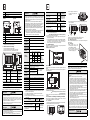
1.1 Part names
Compliance with EC directive (CE Marking)
This document does not guarantee that a mechanical system including this
product will comply with the following standards.
Compliance to EMC directive and LVD directive of the entire mechanical
system should be checked by the user/manufacturer. For more details please
contact the local Mitsubishi Electric sales site.
Attention
This product is designed for use in industrial applications.
Note
Manufactured by:
Mitsubishi Electric Corporation
2-7-3 Marunouchi, Chiyoda-ku, Tokyo, 100-8310 Japan
Manufactured at:
Mitsubishi Electric Corporation Himeji Works
840 Chiyoda-machi, Himeji, Hyogo, 670-8677 Japan
Authorized Representative in the European Community:
Mitsubishi Electric Europe B.V.
Gothaer Str. 8, 40880 Ratingen, Germany
[2]
[3]
[7]
[6]
[8]
[9]
[6]
[5]
[4]
[10]
[3]
[2]
[1]
No.
Name
[1]
DIN rail mounting hooks
[2]
Expansion adapter connecting hooks
[3]
Terminal block covers
Caution for compliance with EC Directive
[4]
Built-in Ethernet communication connector (with cover)
Installation in Enclosure
Programmable controllers are open-type devices that must be installed and
used within conductive control boxes. Please use the FX5U Series
programmable controllers while installed in conductive shielded control boxes.
Please secure the control box lid to the control box (for conduction). Installation
within a control box greatly affects the safety of the system and aids in shielding
noise from the programmable controller.
For other cautions, refer to the MELSEC iQ-F FX5U Series User's Manual
[Hardware].
[5]
Top cover
Operation status display LEDs
PWR
Green
ERR
Red
P.RUN
Green
BAT
[6]
Incorporated Items
Check if the following product and items are included in the package:
CPU module
For the necessary product manuals or documents, consult with your local
Mitsubishi Electric representative.
Manual name
1. Outline
Please consult with Mitsubishi Electric for information on UL, cUL standard
practices and the corresponding types of equipment.
Red
Description
MELSEC iQ-F
FX5 Series
User's Manual
[Startup]
Explains performance
specifications, procedures before
JY997D58201
operation, and troubleshooting of
the FX5 Series PLC.
MELSEC iQ-F
FX5U Series
User's Manual
[Hardware]
Explains FX5U Series PLC
JY997D55301 specification details for I/O, wiring,
installation, and maintenance.
MELSEC iQ-F
FX5 Series
User's Manual
[Serial Communication]
Explains the non-protocol
JY997D55901 communication and inverter
communication.
MELSEC iQ-F
FX5 Series
User's Manual
[MODBUS Communication]
JY997D56101
FX5U-32M,
FX5U-64M,
FX5U-80M
Product
Dust proof protection sheet
1 module
[7]
Lit when the SD memory card is inserted.
RD
Green
Lit when data is received through communication via
built-in RS-485.
SD
Green
Lit when data is sent through communication via
built-in RS-485.
SD/RD
Green
Lit when data is sent or received through
communication via built-in Ethernet.
MELSEC iQ-F
Functions for communication via
FX5 Series
JY997D56201
User's Manual
built-in Ethernet port
[Ethernet Communication]
Expansion board connector cover
1 sheet
[8]
Input display LEDs (Green)
[9]
Extension connector cover
[10]
Output display LEDs (Green)
Product
1 module
Dust proof protection sheet
1 sheet
1 module
Dust proof protection sheet
1 sheet
Extension cable
1 cable
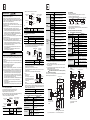
With cover open
[7]
[6]
[5]
[8]
[4]
[9]
[3]
[10]
[2]
[11]
[1]
[7]
No.
[1]
Explains the MODBUS serial
communication.
Lit when the battery voltage drops.
Green
1 manual
Product
FX5-32E
Lit/flashing when an error occurs.
On while the PLC is running.
Manuals [Japanese /English]
I/O module
FX5-8E,
FX5-16E
On while the PLC is powered.
CARD
Included Items
.
Indicates that incorrect handling may cause hazardous
conditions, resulting in death or severe injury.
Certification of UL, cUL standards
Name
Built-in RS-485 communication terminal block
[2]
RS-485 terminal resister selector switch
[3]
RUN/STOP/RESET switch
[4]
SD memory card disable switch
[5]
Built-in analog I/O terminal block
[6]
SD memory card slot
[7]
Terminal block mounting screws
[8]
Expansion board connector
[9]
Extension connector
[11]
Battery connector
Left side
INSTALLATION
PRECAUTIONS
Right side
[1]
[2]
[3]
[4]
No.
Name
[1]
Expansion adapter connector cover
[2]
Label of authenticity*1
[3]
Nameplate*1
[4]
DIN rail mounting groove
Item
2-4.5-diam mounting holes (FX5U-32M)
4-4.5-diam mounting holes (FX5U-64M, FX5U-80M)
FX5U-32M do not have the (*)-marked mounting holes.
Unit: mm (inches)
*
Mounting
hole
pitches
Storage ambient
-25 to 75 (-13 to 167 )
temperature
8 (0.32″)
83 (3.27″)
Model name
W:
mm (inches)
W1:mm (inches)
Mounting hole pitches
MASS (Weight):
kg (lbs.)
FX5U-32M
150 (5.91”)
123 (4.85”)
Approx. 0.65
(1.43 lbs)
FX5U-64M
220 (8.67”)
193 (7.60”)
Approx. 1.0
(2.20 lbs)
FX5U-80M
285 (11.23”)
258 (10.16”)
Approx. 1.2
(2.64 lbs)
Outer paint color Body: Munsell 0.6B7.6/0.2
Between output terminal (relay) and
ground terminal
Between output terminal (transistor) and
ground terminal
Insulation
resistance
1.5 kV AC for
10M or higher by
1 minute
500VDC insulation
500 V AC for resistance tester
1 minute
Expansion boards, expansion adapters, intelligent function module
Between terminal of expansion board and
ground terminal
Not allowed
Not allowed
Between terminal of expansion adapter
and ground terminal
500 V AC for
1 minute
10M or higher by
500VDC insulation
resistance tester
Intelligent function module
Install the PLC in an environment conforming to the generic specifications
(Section 2.1), installation precautions and notes.
Installation location in enclosure
Storage ambient
5 to 95%RH, non-condensing
humidity
As for installation of the I/O modules, expansion adapters and expansion
boards, refer to MELSEC iQ-F FX5U Series User's Manual [Hardware].
INSTALLATION
PRECAUTIONS
Use the product within the generic environment specifications described in
section 2.1 of this manual.
Never use the product in areas with excessive dust, oily smoke,
conductive dusts, corrosive gas (salt air, Cl 2 , H 2 S, SO 2 or NO 2 ), or
flammable gas, subject it to vibration or impact, or expose it to high
temperature, condensation, or rain and wind.
If the product is used in such conditions, electric shock, fire, malfunctions,
deterioration or damage may occur.
INSTALLATION
PRECAUTIONS
Do not touch the conductive parts of the product directly. Doing so may
cause device failures or malfunctions.
When drilling screw holes or wiring, make sure cutting or wire debris does
not enter the ventilation slits of the PLC.
Failure to do so may cause fire, equipment failures or malfunctions.
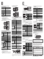
B
4) Lock the DIN rail mounting hooks (below fig. C) while pressing the PLC
against the DIN rail.
C
C
4
4
2.4 Procedures for installing directly (with M4 screws)
The product can be installed directly on the panel (with screws).
This section explains the installation of the CPU modules.
2.4.1
Mounting hole pitches
Refer to the External Dimensions (Section 1.2) for the product's mounting hole
pitch information.
2.4.2
Installation
1) Make mounting holes in the
mounting surface referring to the
external dimensions diagram.
2) Fit the CPU module (right fig. A) B
based on the holes, and secure it
with M4 screws (right fig. B).
Frequency Acceleration Half amplitude
Sweep count
(Hz)
(m/s2)
(mm)
10 to 57
Installed
on DIN rail 57 to 150
0.035
4.9
Installed 10 to 57
directly 57 to 150
0.075
9.8
10 times each
in X, Y, Z
directions
(80 min in
each direction)
Shock resistance*3
147 m/s2 Acceleration, Action time: 11 ms,
3 times by half-sine pulse in each direction X, Y, and Z
Noise durability
By noise simulator of 1000Vp-p noise voltage, 1μs noise
width and 30 to 100Hz noise frequency
1.5 kV AC for 1 minute
Dielectric
withstand voltage*4 500 V AC for 1 minute
Between each terminal
and ground terminal
Insulation
resistance*4
10M or higher by 500VDC
insulation resistance tester
Grounding
Class D grounding (Grounding resistance: 100 or less)
<Common grounding with a heavy electrical system is not allowed.>*5
A
B
3. Specifications and examples of external wiring
Space in enclosure
Extension devices can be connected on the left and right sides of the CPU
module.
If you intend to add extension devices in the future, keep necessary spaces on
the left and right sides.
A
Working atmosphere Free from corrosive or flammable gas and excessive conductive dusts
A
Operating altitude 2000 m or less*6
FX5U Series
CPU module
Installation location Inside a control panel
A
Overvoltage category II or less
2. Installation (general specifications)
3) Fit the upper edge of the DIN rail
mounting groove (right fig. B) onto
the DIN rail.
Each manual
For dielectric withstand voltage test and insulation resistance test of each
product, refer to the following manual.
Refer to MELSEC iQ-F FX5U Series User's Manual [Hardware].
*5 For common grounding, refer to Section 3.3.
*6 The PLC cannot be used at a pressure higher than the atmospheric
pressure to avoid damage.
*7 This index indicates the degree to which conductive material is generated
in the environment in which the equipment is used. Pollution level 2 is
when only non-conductive pollution occurs. Temporary conductivity
caused by condensation must be expected occasionally.
2.2 Installation location
Operating
5 to 95%RH, non-condensing
ambient humidity
Vibration
resistance*3
90 (3.55″)
80 (3.15″)
*
W1
W
Specification
Operating ambient
0 to 55 (32 to 131 )*2
temperature*1
1.2 External dimensions and weight
22
(0.87″)
For product supplied together with a dust proof sheet, the sheet should be
affixed to the ventilation port before installation and wiring work to block
foreign objects such as cutting and wiring debris. However, when the
installation work is completed, make sure to remove the sheet to provide
adequate ventilation.
Failure to do so may cause fire, equipment failures or malfunctions.
Install the product on a flat surface. If the mounting surface is rough, undue
force will be applied to the PC board, thereby causing nonconformities.
Install the product securely using a DIN rail or mounting screws.
Connect the extension cables, peripheral device cables, input/output cables
and battery connecting cable securely to their designated connectors.
Loose connections may cause malfunctions.
Turn off the power to the PLC before attaching or detaching the following devices.
Failure to do so may cause equipment failures or malfunctions.
- Peripheral devices, expansion board, and expansion adapter
- Extension modules, bus conversion module, and battery
2.1 Generic specifications
*1 Products that do not have the genuine product certification label or
nameplate are not covered by the warranty.
Dielectric
strength
Terminal
FX5-16EYT
Name
Battery holder
FX5-16EX
No.
[10]
A
Pollution degree*7 2 or less
A 50mm
Equipment class Class 2
*1 The simultaneous ON ratio of available PLC inputs or outputs changes
with respect to the ambient temperature, refer to MELSEC iQ-F FX5U
Series User's Manual [Hardware].
*2 For intelligent function modules, refer to the manual for each product.
*3 The criterion is shown in IEC61131-2.
*4 Dielectric withstand voltage and insulation resistance are shown in the
following table.
Terminal
Dielectric
strength
Insulation
resistance
CPU modules, I/O modules
Between power supply terminal
(AC power) and ground terminal
Between 24 V DC service power supply
connected to input terminal (24 V DC) and
ground terminal
1.5 kV AC for
1 minute
10M or higher by
500VDC insulation
500 V AC for resistance tester
1 minute
2.2.1
Affixing the dust proof sheet
The dust proof sheet should be affixed to the ventilation port before beginning
the installation and wiring work.
For the affixing procedure, refer to the instructions
on the dust proof sheet.
Be sure to remove the dust proof sheet when the installation and wiring work is
completed.
2.3 Procedures for installing to and detaching from DIN rail
The products can be installed on a DIN46277 rail [35 mm (1.38”) wide]. This
section explains the installations of the CPU modules.
2.3.1
Installation
1) Connect the expansion boards and expansion adapters to the CPU module.
2) Push out all DIN rail mounting hooks (below fig. A)
2
As for the details of the power supply wiring and input/output wiring, refer to
MELSEC iQ-F FX5U Series User's Manual [Hardware].
DESIGN PRECAUTIONS
Make sure to set up the following safety circuits outside the PLC to ensure
safe system operation even during external power supply problems or
PLC failure.
Otherwise, malfunctions may cause serious accidents.
- Most importantly, set up the following: an emergency stop circuit, a
protection circuit, an interlock circuit for opposite movements (such as
forward vs. reverse rotation), and an interlock circuit to prevent
damage to the equipment at the upper and lower positioning limits.
- Note that when the CPU module detects an error, such as a watchdog
timer error, during self-diagnosis, all outputs are turned off. Also, when
an error that cannot be detected by the CPU module occurs in an input/
output control block, output control may be disabled.
External circuits and mechanisms should be designed to ensure safe
machine operation in such a case.
- Note that the output current of the 24V DC service power supply varies
depending on the model and the absence/presence of extension
modules. If an overload occurs, the voltage automatically drops, inputs
in the PLC are disabled, and all outputs are turned off.
External circuits and mechanisms should be designed to ensure safe
machine operation in such a case.
- Note that when an error occurs in a relay, triac or transistor of an output
circuit, the output might stay on or off.
For output signals that may lead to serious accidents, external circuits
and mechanisms should be designed to ensure safe machine operation.
Construct an interlock circuit in the program to ensure safe operation for the
whole system when executing control (for data change) of the PLC in
operation. Read the manual thoroughly and sufficiently ensure complete
safety before executing other controls (for program change, parameter
change, forced output and operation status change) of the PLC in operation.
Otherwise, improper operation may damage machines or cause accidents.
2
DESIGN PRECAUTIONS
2
A
2
A
Simultaneously turn on and off the power supplies of the CPU module and
extension modules.
When two wires are connected to one terminal
WIRING PRECAUTIONS
Item
3.2 (0.13")
Make sure to cut off all phases of the power supply externally before
attempting installation or wiring work.
Failure to do so may cause electric shock or damage to the product.
Make sure to attach the terminal cover, provided as an accessory, before
turning on the power or initiating operation after installation or wiring work.
Failure to do so may cause electric shock.
The temperature rating of the cable should be 80 or more.
Make sure to wire the screw terminal block in accordance with the
following precautions.
Failure to do so may cause electric shock, equipment failures, a shortcircuit, wire breakage, malfunctions, or damage to the product.
- Wire terminals should follow the dimensions described in the manual.
- Tightening torque should follow the specifications in the manual.
- Tighten the screws using a Phillips-head screwdriver No.2 (shaft
diameter 6 mm (0.24”) or less). Make sure that the screwdriver does
not touch the partition part of the terminal block.
Make sure to wire the terminal block (European type) in accordance with
the following precautions.
Failure to do so may cause electric shock, equipment failures, a shortcircuit, wire breakage, malfunctions, or damage to the product.
- Wire terminals should follow the dimensions described in the manual.
- Tightening torque should follow the specifications in the manual.
- Twist the end of stranded wires and make sure that there are no loose wires.
- Do not solder-plate the electric wire ends.
- Do not connect more than the specified number of wires or electric
wires of unspecified size.
- Affix the electric wires so that neither the terminal block nor the
connected parts are directly stressed.
6.3 mm (0.25")
or more
3.2 (0.13")
6.2 mm (0.24")
or less
<Reference>
Type No.
JST Mfg. Co., Ltd.
FV1.25-B3A
3.1.2
Certification
Pressure Bonding Tool
UL Listed
YA-1 (JST Mfg. Co., Ltd.)
3.1 Cable end treatment and tightening torque
3.1.1
Screw type terminal block
For the terminals of FX5U Series PLC, M3 screws are used.
The electric wire ends should be treated as shown below.
Tighten the screws to a torque of 0.5 to 0.8 Nm.
Do not tighten terminal screws with a torque outside the above-mentioned range.
Failure to do so may cause equipment failures or malfunctions.
When one wire is connected to one terminal
3.2 (0.13")
Terminal Solderless
screw
terminal
6.2 mm (0.24")
or less
3.2 (0.13")
6.2 mm (0.24")
or less
Terminal
<Reference>
Terminal Manufacturer
JST Mfg. Co., Ltd.
Type No.
FV1.25-B3A
FV2-MS3
Certification
Pressure Bonding
Tool
UL Listed
YA-1
(JST Mfg. Co., Ltd.)
30 A max. 5 ms or less/100 V AC
60 A max. 5 ms or less/200 V AC
FX5-32E
30 A max. 5 ms or less/100 V AC
65 A max. 5 ms or less/200 V AC
FX5U-32M
30 W
FX5U-64M
Power
consumption*1 FX5U-80M
40 W
FX5-32E
European type terminal block
1) Wire size
Wire size
No. of wire
per terminal
Solid wire/Stranded wire
Ferrules with insulating sleeve
1
AWG24 to 20
AWG24 to 20
2
AWG24
2) Treatment of wire ends
Strip the coating of strand wire and twist the cable core before connecting
it, or strip the coating of single wire before connecting it. An alternative
connection is to use a ferrule with insulating sleeve.
Contact area
Insulating sleeve
(Crimp area)
5 mm
(0.19")
6 mm
(0.23")
2 to 2.5 mm
(0.07" to 0.09")
10.5 to 12 mm
(0.41" to 0.47")
Manufacturer
Model
Caulking tool
Phoenix Contact GmbH & Co. KG
AI 0.5-6WH
CRIMPFOX 6
When using a wire ferrule with an insulating sleeve, choose a wire with
proper cable sheath referring to the above outside dimensions, otherwise
the wire cannot be inserted easily.
Tighten the screws to a torque of 0.22 to 0.25 Nm.
Do not tighten terminal screws exceeding with a torque outside the abovementioned range.
Failure to do so may cause equipment failures or malfunctions.
3) Tool
For tightening the
With
terminal, use a
straight tip
com merc ial ly av ail abl e s mal l
screwdriver having a straight form
that is not widened toward the end
0.4 mm
2.5 mm
as shown right.
(0.01")
(0.09")
24 V DC
service power
supply
capacity*2
FX5U-64M
FX5U-80M
Model names
Phoenix Contact GmbH & Co. KG
SZS 0.4×2.5
400 mA (When 24 V DC service power
supply is supplied to the input circuit)
3.2.2
Power supply specifications [CPU module, FX5-32E]
Item
100 to 240 V AC
Allowable supply voltage
range
85 to 264 V AC
Frequency rating
50/60 Hz
Allowable instantaneous
power failure time
Operation can be continued upon
occurrence of instantaneous power failure
for 10 ms or less.
Power fuse
250 V 3.15 A Time-lag Fuse
FX5U-64M,
FX5U-80M
250 V 5 A Time-lag Fuse
Shared grounding
(Good condition)
Item
740 mA (When external power supply is
supplied to the input circuit)
Input
impedance
600 mA (When 24 V DC service power
supply is supplied to the input circuit)
770 mA (When external power supply is
supplied to the input circuit)
Common grounding
(Not allowed)
Specification
24 V DC 20%, -15%
CPU
module
Input signal
current
X000 to X017
4.3 k
X020 or more
5.6 k
FX5 series I/O module
5.6 k
CPU
module
X000 to X017
5.3 mA/24 V DC
X020 or more
4 mA/24 V DC
FX5 series I/O module
4 mA/24 V DC
CPU
module
ON input
sensitivity
current
X000 to X017
3.5 mA or more
X020 or more
3.0 mA or more
FX5 series I/O module
3.0 mA or more
900 mA
OFF input sensitivity current
1.5 mA or less
1100 mA
Input response time
Refer to MELSEC iQ-F FX5U
Series User's Manual [Hardware]
965 mA
Example of external wiring
Sink input
No-voltage contact input NPN
open collector transistor
Source input
No-voltage contact input PNP
open collector transistor
Input signal form
Input operation display
3.4.2
LED on panel turns on when input.
Examples of input wiring (when 24 V DC service power supply
is used)
1. Sink input type
2. Source input type
[1]
L
100 to 240 V AC power is supplied to the CPU module and FX5-32E. For the
details of wiring work, refer to Section 3.1.
100 to 240 V AC
N
Breaker
S/S
0V
24V
[1]
Fuse
L
Power on
PL
[1]
Emergency
X000
X001
X002
X003
MC
MC
Fuse
N
100 to 240 V AC
N
MC
3-wire type
sensor
MC
S/S
X000
* Class D grounding
See section 3.3 for details.
* Class D grounding
See section 3.3 for
details.
[1]: CPU module, FX5-32E
S/S
0V
24V
[2]
*
[1]: CPU module, FX5-32E
[2]: Input module
DC
power
supply
AC
Power supply for loads connected
to CPU module output terminals
Fuse
*
*
100 to 240 V AC
L
Other
equipment
PLC
Input specifications (24 V DC input type)
Input signal voltage
DC
FX5U-32M,
FX5-32E
3.4.1
600 mA (When 24 V DC service power
supply is supplied to the input circuit)
Specification
Rated voltage
Other
equipment
3.4 Input specifications and external wiring
480 mA (When external power supply is
supplied to the input circuit)
*1 This item shows value when all 24 V DC service power supplies are used
in the maximum configuration connectable to the CPU module. (The
current of the input circuit is included.)
*2 When I/O modules are connected, they consume current from the 24 V
DC service power.
*3 Power is supplied to I/O modules, intelligent function modules, expansion
adapters and expansion boards.
The following manual shows further information.
Refer to MELSEC iQ-F FX5U Series User’s Manual [Hardware].
3.2 Power supply specifications and external wiring
3.2.1
Independent grounding
(Best condition)
310 mA (When external power supply is
supplied to the input circuit)
FX5U-32M
5 V DC built-in
power supply FX5U-64M,
FX5U-80M
capacity*3
FX5-32E
PLC
Use ground wires thicker than AWG14 (2 mm2).
Position the grounding point as close to the PLC as possible to decrease the
length of the ground wire.
250 mA (When 24 V DC service power
supply is supplied to the input circuit)
FX5-32E
Other
equipment
PLC
45 W
Note:
If the diameter of screwdriver grip is too small, tightening torque may not be
achieved. To achieve the appropriate tightening torque shown in the table
above, use the following screwdriver or appropriate replacement (grip
diameter: approximately 25 mm (0.98")).
Manufacturer
Ground the PLC as stated below.
Perform class D grounding. (Grounding resistance: 100 or less)
Ground the PLC independently if possible.
If it cannot be grounded independently, ground it jointly as shown below.
25 W
FX5U-32M
WIRING PRECAUTIONS
Perform class D grounding (grounding resistance: 100 or less) of the grounding
terminal on the CPU module and extension modules with a wire 2 mm2 or thicker.
Do not use common grounding with heavy electrical systems (refer to
section 3.3).
Connect the power supply wiring to the dedicated terminals described in
this manual.
If an AC power supply is connected to a DC input/output terminal or DC
power supply terminal, the PLC will burn out.
Do not wire vacant terminals externally.
Doing so may damage the product.
Make sure to observe the following precautions in order to prevent any
damage to the machinery or accidents due to malfunction of the PLC
caused by abnormal data written to the PLC due to the effects of noise.
- Do not bundle the power line, control line and communication cables
together with or lay them close to the main circuit, high-voltage line,
load line or power line. As a guideline, lay the power line, control line
and communication cables at least 100 mm (3.94”) away from the main
circuit, high-voltage line, load line or power line.
- Ground the or shield of the shielded wire or shielded cable at one point
on the PLC. However, do not use common grounding with heavy
electrical systems.
- Ground the shield of the analog input/output cable at one point on the
signal receiving side.
However, do not use common grounding with heavy electrical systems.
FX5U-64M,
FX5U-80M
Terminal
6.3 mm (0.25")
or more
Terminal
Manufacturer
25 A max. 5 ms or less/100 V AC
50 A max. 5 ms or less/200 V AC
Rush current
3.3 Grounding
Specification
FX5U-32M
Terminal Solderless
screw
terminal
6.2 mm (0.24")
or less
X000
X001
X002
X003
[2]
S/S
X000
3-wire type
sensor
3.5 Relay output specifications and external wiring
3.6.2
3.5.1
1. External wiring of sink output type
Load
Y000
Relay output specifications
Item
Specification
External power supply
30 V DC or less
240 V AC or less ("250 V AC or less" if not a
CE, UL, cUL compliant item)
Max. load
2 A/point*1
Min. load
5 V DC, 2 mA (reference value)
OFFON
LED on panel turns on when output.
+V0
3.7
Built-in analog input/output specifications and external wiring
As for the details on the built-in analog input/output specifications and external
wiring, refer to the following manual.
Refer to MELSEC iQ-F FX5U Series User's Manual [Hardware].
3.7.1
Analog input specifications
Item
Specifications
2 points (2 channels)
Y000
Y001
Analog input
0 to 10 V DC (Input resistance: 115.7 k)
Digital output
12 bit unsigned binary
COM0
Device allocation
SD6020 (Input data of ch1)
SD6060 (Input data of ch2)
Y010
Y011
I/O
characteristics,
Maximum
resolution
Fuse
Digital output
value
0 to 4000
Maximum
resolution
2.5 mV
COM2
Accuracy (Accuracy in
respect to maximum digital
output value)
CPU module
100 V AC
3.6 Transistor output specifications and external wiring
3.6.1
Transistor output specifications
Item
Output
form
Specification
FX5U-MT/ES,
FX5-EYT/ES, FX5-32ET/ES
Transistor (Sink)
FX5U-MT/ESS,
FX5-EYT/ESS, FX5-32ET/ESS
Transistor (Source)
5 to 30 V DC
Max. load
0.5 A/point*1
Channel 2 analog input (+)
V-
Analog input (-)*1
V+
Analog output (+)
V-
Analog output (-)
*1 The V- terminals are connected internally.
3.8 Built-in Ethernet communication specifications and
external wiring
As for the details on the built-in Ethernet communication specifications and
external wiring, refer to the following manual.
Refer to MELSEC iQ-F FX5 Series User's Manual
[Ethernet Communication].
Transmission method
Base band
Maximum segment length
100 m
Cascade connection maximum 4 stages*1
Maximum number of 10BASE-T
nodes/connection
100BASE-TX Cascade connection maximum 2 stages*1
-0.5 V, +15 V
Insulation method
No insulation between each channel or the PLC.
Protocol type
MELSOFT connection, SLMP (3E frames),
Socket communication
Occupied points
0 point (Dose not occupy of input and
output points of the PLC.)
Number of simultaneously open
connections allowed
MELSOFT connection + SLMP +
Socket communication 8
Analog output specifications
Item
Specifications
Insulation method
Pulse transformer
Connector
RJ-45
*1 The value indicates the number of connectable stages when a repeater
hub is used.
Contact the manufacturer of the switching hub for the number of
connectable stages when using a switching hub.
1.0 V or less
Y004 or more
1.5 V or less
I/O
characteristics,
Maximum
resolution
*1 The total load current of resistance loads per common terminal should be
the following value.
- 4 output point/common terminal: 0.8 A or less
- 8 output point/common terminal: 1.6 A or less
As for the number of outputs per common terminal, refer to Chapter 4 and
the following manual.
Refer to MELSEC iQ-F FX5U Series User's Manual [Hardware].
Digital input
value
0 to 4000
Maximum
resolution
2.5 mV
3.8.3
When ambient temperature is 25 5
Within 0.5% (20 digit)*1
When ambient temperature is 0 to 55
Within 1.0% (40 digit)*1
Insulation method
No insulation between the PLC.
Occupied points
0 point (Dose not occupy any input and
output points of the PLC.)
*1 Digit indicates a digital value.
Class D
grounding
V+
V*2
Pin Configuration
8
Example of analog input
*1
Wiring
The connector of the built-in Ethernet communication are arranged as follows:
Accuracy (Accuracy in
respect to maximum analog
output value)
3.7.3
Insulation method
No insulation between the PLC.
Terminal resistors
Built-in (OPEN/110 /330 )
Connection method
European terminal block
82.7 k
1
ch
33 k
V+, ch: represents the channel number
*1 Use 2-core shielded twisted pair cable for the analog input lines, and
separate the analog input lines from other power lines or inductive lines.
*2 Make sure to short-circuit the "V+" and "V-" terminals when channel is
not used.
3.9.2
Wiring
For the wiring, refer to the following manual.
Refer to MELSEC iQ-F FX5 Series User's Manual
[Serial Communication].
Refer to MELSEC iQ-F FX5 Series User's Manual
[MODBUS Communication].
3.9.3
Terminal block layouts
The terminals of the built-in RS-485 communication are arranged as follows:
Signal name
Function
RDA
Receive data
RDB
Send data
SG
Y000 to Y003
LED on panel turns on
when output.
MELSOFT connection,
Non-protocol communication, MODBUS RTU,
Inverter communication
SDB
For the wiring, refer to the following manual.
Refer to MELSEC iQ-F FX5 Series User's Manual
[Ethernet Communication].
0.2 ms or less/200 mA
or more (at 24 V DC)
Protocol type
Full-duplex/Half-duplex
3.8.2
0.2 ms or less/200 mA
or more (at 24 V DC)
50 m
Communication method
SD6180 (Output setting data of ch1)
Y004 or more
Maximum total extension
distance
SDA
0 to 10 V DC (Input resistance: 2k to 1M)
2.5 s or less/10 mA
or more (5 to 24 V DC)
Full-duplex/Half-duplex
Specification
Device allocation
Y000 to Y003
Max. 115.2k bps
Communication method
100Mbps/10Mbps
0.1 mA or less/30 V DC
1.5 V or less
Data transmission speed
Data transmission speed
Absolute maximum input
3.7.2
In conformance to RS-485/RS-422
SG SDB SDA RDB RDA
Communication specification
Item
When ambient temperature is 25 5
Within 0.5% (20 digit)*1
When ambient temperature is 0 to 55
Within 1.0% (40 digit)*1
*1
12 bit unsigned binary
I/O module
Output operation display
Channel 1 analog input (+)
V2+
Analog output
I/O module
OFF
ON
V1+
Digital input
Open circuit leakage current
Response
time
Application
1 points (1 channels)
CPU
module
Analog
output
Signal
Analog output points
Min. load
CPU
module
V1+ V2+ V- V+ VAnalog
Analog
input
output
3.8.1
*1 Digit indicates a digital value.
External power supply
ON voltage
Analog
input
CPU module
Analog input points
Fuse
24 V DC
Load
Terminal block layouts
Specification
Transmission standard
The terminals of the built-in analog input/output are arranged as follows:
24 V DC
Example of relay output wiring
Load
3.7.5
Y000
Y001
*1 The total load current of resistance loads per common terminal should be
the following value.
- 4 output points/common terminal: 8 A or less
- 8 output points/common terminal: 8 A or less
As for the number of outputs per common terminal, refer to
Chapter 4 and the following manual.
Refer to MELSEC iQ-F FX5U Series User's Manual [Hardware].
3.5.2
CPU module
Communication specification
Item
Class D grounding
*1 Use 2-core shielded twisted pair cable for the analog output lines, and
separate the analog output lines from other power lines or inductive lines.
*2 Ground the shielded wire at one point on the signal receiving side.
2. External wiring of source output type
Fuse
3.9.1
V+
V-
*2
COM0
Load
3.9 Built-in RS-485 communication specifications and
external wiring
Example of analog output
*1
24 V DC
Approx. 10 ms
Output operation display
3.7.4
Y001
Fuse
Open circuit leakage current
Response
time
External wiring of transistor output
Pin No.
Signal
1
TXD+
Transmit data (+)
Contents
2
TXD-
Transmit data (-)
3
RXD+
Receive data (+)
4
Not used
5
Not used
6
RXD-
7
Not used
8
Not used
Signal ground
4. Terminal block layouts
For details on the terminal block layout, refer to the following manual.
Refer to MELSEC iQ-F FX5U Series User's Manual [Hardware].
Interpretation of partition
The partition of the output terminals (see following figure) indicates the range of
the output connected to the same common.
Example: FX5U-32MT/ES
Output terminal
Y0
COM0
Y4
2
1
3
COM1
Partition
This manual confers no industrial property rights or any rights of any other kind,
nor does it confer any patent licenses. Mitsubishi Electric Corporation cannot be
held responsible for any problems involving industrial property rights which may
occur as a result of using the contents noted in this manual.
Warranty
Mitsubishi will not be held liable for damage caused by factors found not to be
the cause of Mitsubishi; opportunity loss or lost profits caused by faults in the
Mitsubishi products; damage, secondary damage, accident compensation
caused by special factors unpredictable by Mitsubishi; damages to products
other than Mitsubishi products; and to other duties.
For safe use
Receive data (-)
Applicable cable
10BASE-T
Cable conforming to Ethernet standard practice:
Category 3 or higher (STP cable)
100BASE-TX
Cable conforming to Ethernet standard practice:
Category 5 or higher (STP cable)
A straight cable is used. A cross cable can also be used when using direct
connection (simple connection) between a personal computer and the FX5U
Series PLC.
This product has been manufactured as a general-purpose part for general
industries, and has not been designed or manufactured to be incorporated in
a device or system used in purposes related to human life.
Before using the product for special purposes such as nuclear power, electric
power, aerospace, medicine or passenger movement vehicles, consult with
Mitsubishi Electric.
This product has been manufactured under strict quality control. However
when installing the product where major accidents or losses could occur if the
product fails, install appropriate backup or failsafe functions in the system.
HEAD OFFICE : TOKYO BUILDING, 2-7-3 MARUNOUCHI, CHIYODA-KU, TOKYO 100-8310, JAPAN
HIMEJI WORKS : 840, CHIYODA MACHI, HIMEJI, JAPAN


![MELSEC iQ-F FX5U Series User`s Manual [Hardware]](http://vs1.manualzilla.com/store/data/005848866_1-47292304553905fa63d352e8811bb59a-150x150.png)