1
MELSEC iQ-F FX5 User's Manual (Startup) SAFETY PRECAUTIONS (Read these precautions before use.) Before using this product, please read this manual and the relevant manuals introduced in this manual carefully and pay attention to safety in order to handle the product correctly. This manual classifies the safety precautions into two categories: [ WARNING] and [ CAUTION]. WARNING Indicates that incorrect handling may cause hazardous conditions, resulting in death or severe injury. CAUTION Indicates that incorrect handling may cause hazardous conditions, resulting in minor or moderate injury or property damage. Depending on the circumstances, procedures indicated by [ CAUTION] may also cause severe injury. It is important to follow all precautions for personal safety. Store this manual in a safe place so that it can be read whenever necessary. Always forward it to the end user. [DESIGN PRECAUTIONS] WARNING ● Make sure to set up the following safety circuits outside the PLC to ensure safe system operation even during external power supply problems or PLC failure. Otherwise, malfunctions may cause serious accidents. - Most importantly, set up the following: an emergency stop circuit, a protection circuit, an interlock circuit for opposite movements (such as forward vs. reverse rotation), and an interlock circuit to prevent damage to the equipment at the upper and lower positioning limits. - Note that when the CPU module detects an error, such as a watchdog timer error, during selfdiagnosis, all outputs are turned off. Also, when an error that cannot be detected by the CPU module occurs in an input/output control block, output control may be disabled. External circuits and mechanisms should be designed to ensure safe machine operation in such a case. - Note that the output current of the 24 V DC service power supply varies depending on the model and the absence/presence of extension modules. If an overload occurs, the voltage automatically drops, inputs in the PLC are disabled, and all outputs are turned off. External circuits and mechanisms should be designed to ensure safe machine operation in such a case. - Note that when an error occurs in a relay or transistor of an output circuit, the output might stay on or off. For output signals that may lead to serious accidents, external circuits and mechanisms should be designed to ensure safe machine operation. ● Construct an interlock circuit in the program to ensure safe operation for the whole system when executing control (for data change) of the PLC in operation. Read the manual thoroughly and ensure complete safety before executing other controls (for program change, parameter change, forced output and operation status change) of the PLC in operation. Otherwise, the machine may be damaged and accidents may occur due to erroneous operations. ● In an output circuit, when a load current exceeding the current rating or an overcurrent caused by a load short-circuit flows for a long time, it may cause smoke and fire. To prevent this, configure an external safety circuit, such as a fuse. ● For the operating status of each station after a communication failure of the network, refer to relevant manuals for the network. Incorrect output or malfunction may result in an accident. 1 [DESIGN PRECAUTIONS] CAUTION ● When an inductive load such as a lamp, heater, or solenoid valve is controlled, a large current (approximately ten times greater than normal) may flow when the output is turned from off to on. Take proper measures so that the flowing current does not exceed the value corresponding to the maximum load specification of the resistance load. ● After the CPU module is powered on or is reset, the time taken to enter the RUN status varies depending on the system configuration, parameter settings, and/or program size. Design circuits so that the entire system will always operate safely, regardless of this variation in time. ● Simultaneously turn on and off the power supplies of the CPU module and extension modules. ● If a long-time power failure or an abnormal voltage drop occurs, the PLC stops, and output is turned off. When the power supply is restored, it will automatically restart (when the RUN/STOP/RESET switch is on RUN). [INSTALLATION PRECAUTIONS] WARNING ● Make sure to cut off all phases of the power supply externally before attempting installation or wiring work. Failure to do so may cause electric shock or damage to the product. ● Use the product within the generic environment specifications described in the FX5 User's Manual (Hardware). Never use the product in areas with excessive dust, oily smoke, conductive dusts, corrosive gas (salt air, Cl2, H2S, SO2 or NO2), flammable gas, vibration or impacts, or expose it to high temperature, condensation, or rain and wind. If the product is used in such conditions, electric shock, fire, malfunctions, deterioration or damage may occur. [INSTALLATION PRECAUTIONS] CAUTION ● Do not touch the conductive parts of the product directly. Doing so may cause device failures or malfunctions. ● When drilling screw holes or wiring, make sure that cutting and wiring debris do not enter the ventilation slits of the PLC. Failure to do so may cause fire, equipment failures or malfunctions. ● For product supplied together with a dust proof sheet, the sheet should be affixed to the ventilation slits before the installation and wiring work in order to block foreign objects such as cutting and wiring debris. However, when the installation work is completed, make sure to remove the sheet to provide adequate ventilation. Failure to do so may cause fire, equipment failures or malfunctions. ● Install the product on a flat surface. If the mounting surface is rough, undue force will be applied to the PC board, thereby causing nonconformities. ● Install the product securely using a DIN rail or mounting screws. ● Connect the expansion board and expansion adapter securely to their designated connectors. Loose connections may cause malfunctions. ● Make sure to affix the expansion board with tapping screws. Tightening torque should follow the specifications in the manual. If the screws are tightened outside of the specified torque range, poor connections may cause malfunctions. 2 CAUTION ● Work carefully when using a screwdriver during product installation. Failure to do so may cause damage to the product or accidents. ● Connect the extension cables, peripheral device cables, input/output cables and battery connecting cable securely to their designated connectors. Loose connections may cause malfunctions. ● When using an SD memory card, insert it into the SD memory card slot. Check that it is inserted completely. Poor contact may cause malfunction. ● Turn off the power to the PLC before attaching or detaching the following devices. Failure to do so may cause device failures or malfunctions. - Peripheral devices, expansion board and expansion adapter - Extension modules and bus conversion module - Battery [WIRING PRECAUTIONS] WARNING ● Make sure to cut off all phases of the power supply externally before attempting installation or wiring work. Failure to do so may cause electric shock or damage to the product. ● Make sure to attach the terminal cover, provided as an accessory, before turning on the power or initiating operation after installation or wiring work. Failure to do so may cause electric shock. ● The temperature rating of the cable should be 80 or more. ● Make sure to wire the screw terminal block in accordance with the following precautions. Failure to do so may cause electric shock, equipment failures, a short-circuit, wire breakage, malfunctions, or damage to the product. - Wire terminals should follow the dimensions described in the FX5 User's Manual (Hardware). - Tightening torque should follow the specifications in the FX5 User's Manual (Hardware). - Tighten the screws using a Phillips-head screwdriver No. 2 (shaft diameter 6 mm (0.24") or less). Make sure that the screwdriver does not touch the partition part of the terminal block. ● Make sure to wire the terminal block (European type) in accordance with the following precautions. Failure to do so may cause electric shock, equipment failures, a short-circuit, wire breakage, malfunctions, or damage to the product. - Wire terminals should follow the dimensions described in the FX5 User's Manual (Hardware). - Tightening torque should follow the specifications in the FX5 User's Manual (Hardware). - Twist the ends of stranded wires and make sure that there are no loose wires. - Do not solder-plate the electric wire ends. - Do not connect more than the specified number of wires or electric wires of unspecified size. - Affix the electric wires so that neither the terminal block nor the connected parts are directly stressed. 3 [WIRING PRECAUTIONS] CAUTION ● Do not supply power to the [24+] and [24V] terminals (24 V DC service power supply) on the CPU module or extension modules. Doing so may cause damage to the product. ● Perform class D grounding (grounding resistance: 100 or less) of the grounding terminal on the CPU module and extension modules with a wire 2 mm2 or thicker. However, do not use common grounding (refer to the FX5 User's Manual (Hardware)) with heavy electrical systems. ● Connect the power supply wiring to the dedicated terminals described in the FX5 User's Manual (Hardware). If an AC power supply is connected to a DC input/output terminal or DC power supply terminal, the PLC will burn out. ● Do not wire vacant terminals externally. Doing so may cause damage to the product. ● Install module so that excessive force will not be applied to terminal blocks, power connectors, I/O connectors, communication connectors, or communication cables. Failure to do so may result in wire damage/breakage or PLC failure. ● Make sure to observe the following precautions in order to prevent any damage to the machinery or accidents due to malfunction of the PLC caused by abnormal data written to the PLC due to the effects of noise. - Do not bundle the power line, control line and communication cables together with or lay them close to the main circuit, high-voltage line, load line or power line. As a guideline, lay the power line, control line and connection cables at least 100 mm (3.94") away from the main circuit, highvoltage line, load line or power line. - Ground the shield of the shield wire or shielded cable at one point on the PLC. However, do not use common grounding with heavy electrical systems. - Ground the shield of the analog input/output cable at one point on the signal receiving side. Do not use common grounding with heavy electrical systems. [STARTUP AND MAINTENANCE PRECAUTIONS] WARNING ● Do not touch any terminal while the PLC's power is on. Doing so may cause electric shock or malfunctions. ● Before cleaning or retightening terminals, cut off all phases of the power supply externally. Failure to do so may cause electric shock. ● Before modifying the program in mid-operation, forcing output, running or stopping the PLC, read through this manual carefully, and ensure complete safety. An operation error may damage the machinery or cause accidents. ● Do not change the program in the PLC from two or more peripheral equipment devices at the same time. (i.e. from an engineering tool and a GOT) Doing so may cause destruction or malfunction of the PLC program. 4 WARNING ● Use the battery for memory backup in conformance to the FX5 User’s Manual (Hardware). - Use the battery for the specified purpose only. - Connect the battery correctly. - Do not charge, disassemble, heat, put in fire, short-circuit, connect reversely, weld, swallow or burn the battery, or apply excessive force (vibration, impact, drop, etc.) to the battery. - Do not store or use the battery at high temperatures or expose to direct sunlight. - Do not expose to water, bring near fire or touch liquid leakage or other contents directly. Incorrect handling of the battery may cause excessive heat, bursting, ignition, liquid leakage or deformation, and lead to injury, fire or failures and malfunction of facilities and other equipment. [STARTUP AND MAINTENANCE PRECAUTIONS] CAUTION ● Do not disassemble or modify the PLC. Doing so may cause fire, equipment failures, or malfunctions. *For repair, contact your local Mitsubishi Electric representative. ● After the first use of the SD memory card, do not insert/remove the memory card more than 500 times. Insertion/removal 500 times or more may cause malfunction. ● Turn off the power to the PLC before connecting or disconnecting any extension cable. Failure to do so may cause device failures or malfunctions. ● Turn off the power to the PLC before attaching or detaching the following devices. Failure to do so may cause device failures or malfunctions. - Peripheral devices, expansion board and expansion adapter - Extension modules and bus conversion module - Battery [OPERATION PRECAUTIONS] CAUTION ● Construct an interlock circuit in the program to ensure safe operation for the whole system when executing control (for data change) of the PLC in operation. Read the manual thoroughly and ensure complete safety before executing other controls (for program change, parameter change, forced output and operation status change) of the PLC in operation. Otherwise, the machine may be damaged and accidents may occur by erroneous operations. [DISPOSAL PRECAUTIONS] CAUTION ● Please contact a certified electronic waste disposal company for the environmentally safe recycling and disposal of your device. ● When disposing of batteries, separate them from other waste according to local regulations. For details on the Battery Directive in EU countries, refer to the FX5 User's Manual (Hardware). 5 [TRANSPORTATION PRECAUTIONS] CAUTION ● When transporting the PLC with the optional battery, turn on the PLC before shipment, confirm that the battery mode is set in PLC parameters and the BAT LED is OFF, and check the battery life. If the PLC is transported with the BAT LED on or the battery exhausted, the battery-backed data may be lost during transportation. ● The PLC is a precision instrument. During transportation, avoid impacts larger than those specified in the general specifications of the FX5 User's Manual (Hardware) by using dedicated packaging boxes and shock-absorbing palettes. Failure to do so may cause failures in the PLC. After transportation, verify operation of the PLC and check for damage of the mounting part, etc. ● When transporting lithium batteries, follow required transportation regulations. For details on the regulated products, refer to the FX5 User's Manual (Hardware). ● Fumigants that contain halogen materials such as fluorine, chlorine, bromine, and iodine used for disinfecting and protecting wooden packaging from insects will cause malfunction in Mitsubishi products. Please take necessary precautions to ensure that residual fumigants do not enter the product, or treat packaging with methods other than fumigation (heat method). Additionally, disinfect and protect wood from insects before packing. 6 INTRODUCTION This manual contains text, diagrams and explanations which will guide the reader in the correct installation, safe use and operation of the FX5 Programmable Controllers and should be read and understood before attempting to install or use the module. Always forward it to the end user. Regarding use of this product • This product has been manufactured as a general-purpose part for general industries, and has not been designed or manufactured to be incorporated in a device or system used in purposes related to human life. • Before using the product for special purposes such as nuclear power, electric power, aerospace, medicine or passenger movement vehicles, consult Mitsubishi Electric. • This product has been manufactured under strict quality control. However when installing the product where major accidents or losses could occur if the product fails, install appropriate backup or failsafe functions in the system. Note • If in doubt at any stage during the installation of the product, always consult a professional electrical engineer who is qualified and trained in the local and national standards. If in doubt about the operation or use, please consult the nearest Mitsubishi Electric representative. • Since the examples indicated by this manual, technical bulletin, catalog, etc. are used as a reference, please use it after confirming the function and safety of the equipment and system. Mitsubishi Electric will accept no responsibility for actual use of the product based on these illustrative examples. • This manual content, specification etc. may be changed without a notice for improvement. • The information in this manual has been carefully checked and is believed to be accurate; however, if you notice a doubtful point, an error, etc., please contact the nearest Mitsubishi Electric representative. When doing so, please provide the manual number given at the end of this manual. 7 CONTENTS SAFETY PRECAUTIONS . . . . . . . . . . . . . . . . . . . . . . . . . . . . . . . . . . . . . . . . . . . . . . . . . . . . . . . . . . . . . . . . . . . .1 INTRODUCTION . . . . . . . . . . . . . . . . . . . . . . . . . . . . . . . . . . . . . . . . . . . . . . . . . . . . . . . . . . . . . . . . . . . . . . . . . . .7 RELEVANT MANUALS . . . . . . . . . . . . . . . . . . . . . . . . . . . . . . . . . . . . . . . . . . . . . . . . . . . . . . . . . . . . . . . . . . . . .10 TERMS . . . . . . . . . . . . . . . . . . . . . . . . . . . . . . . . . . . . . . . . . . . . . . . . . . . . . . . . . . . . . . . . . . . . . . . . . . . . . . . . . 11 CHAPTER 1 1.1 PART NAMES 13 FX5U CPU module . . . . . . . . . . . . . . . . . . . . . . . . . . . . . . . . . . . . . . . . . . . . . . . . . . . . . . . . . . . . . . . . . . . . . . . 13 Front panel . . . . . . . . . . . . . . . . . . . . . . . . . . . . . . . . . . . . . . . . . . . . . . . . . . . . . . . . . . . . . . . . . . . . . . . . . . . . . 13 Side . . . . . . . . . . . . . . . . . . . . . . . . . . . . . . . . . . . . . . . . . . . . . . . . . . . . . . . . . . . . . . . . . . . . . . . . . . . . . . . . . . . 15 1.2 Part Names. . . . . . . . . . . . . . . . . . . . . . . . . . . . . . . . . . . . . . . . . . . . . . . . . . . . . . . . . . . . . . . . . . . . . . . . . . . . . 16 Front panel . . . . . . . . . . . . . . . . . . . . . . . . . . . . . . . . . . . . . . . . . . . . . . . . . . . . . . . . . . . . . . . . . . . . . . . . . . . . . 16 Side . . . . . . . . . . . . . . . . . . . . . . . . . . . . . . . . . . . . . . . . . . . . . . . . . . . . . . . . . . . . . . . . . . . . . . . . . . . . . . . . . . . 17 CHAPTER 2 2.1 SPECIFICATIONS 18 Performance Specifications . . . . . . . . . . . . . . . . . . . . . . . . . . . . . . . . . . . . . . . . . . . . . . . . . . . . . . . . . . . . . . . 18 CHAPTER 3 FUNCTION LIST 20 CHAPTER 4 PROCEDURES BEFORE OPERATION 22 4.1 Installing a Battery . . . . . . . . . . . . . . . . . . . . . . . . . . . . . . . . . . . . . . . . . . . . . . . . . . . . . . . . . . . . . . . . . . . . . . 23 FX5U CPU module . . . . . . . . . . . . . . . . . . . . . . . . . . . . . . . . . . . . . . . . . . . . . . . . . . . . . . . . . . . . . . . . . . . . . . . 23 FX5UC CPU module . . . . . . . . . . . . . . . . . . . . . . . . . . . . . . . . . . . . . . . . . . . . . . . . . . . . . . . . . . . . . . . . . . . . . . 24 4.2 Inserting and Removing an SD Memory card . . . . . . . . . . . . . . . . . . . . . . . . . . . . . . . . . . . . . . . . . . . . . . . . . 25 4.3 Creating a Project . . . . . . . . . . . . . . . . . . . . . . . . . . . . . . . . . . . . . . . . . . . . . . . . . . . . . . . . . . . . . . . . . . . . . . . 26 4.4 Connecting a Personal Computer . . . . . . . . . . . . . . . . . . . . . . . . . . . . . . . . . . . . . . . . . . . . . . . . . . . . . . . . . . 27 4.5 Initializing the CPU Module . . . . . . . . . . . . . . . . . . . . . . . . . . . . . . . . . . . . . . . . . . . . . . . . . . . . . . . . . . . . . . . 28 4.6 Setting Parameters . . . . . . . . . . . . . . . . . . . . . . . . . . . . . . . . . . . . . . . . . . . . . . . . . . . . . . . . . . . . . . . . . . . . . . 28 4.7 Programming . . . . . . . . . . . . . . . . . . . . . . . . . . . . . . . . . . . . . . . . . . . . . . . . . . . . . . . . . . . . . . . . . . . . . . . . . . . 30 Registering labels . . . . . . . . . . . . . . . . . . . . . . . . . . . . . . . . . . . . . . . . . . . . . . . . . . . . . . . . . . . . . . . . . . . . . . . . 30 Inserting program elements. . . . . . . . . . . . . . . . . . . . . . . . . . . . . . . . . . . . . . . . . . . . . . . . . . . . . . . . . . . . . . . . . 31 Inserting program elements by key input. . . . . . . . . . . . . . . . . . . . . . . . . . . . . . . . . . . . . . . . . . . . . . . . . . . . . . . 33 4.8 Converting the Program . . . . . . . . . . . . . . . . . . . . . . . . . . . . . . . . . . . . . . . . . . . . . . . . . . . . . . . . . . . . . . . . . . 34 4.9 Saving the Project . . . . . . . . . . . . . . . . . . . . . . . . . . . . . . . . . . . . . . . . . . . . . . . . . . . . . . . . . . . . . . . . . . . . . . . 34 4.10 Writing Data to the CPU Module. . . . . . . . . . . . . . . . . . . . . . . . . . . . . . . . . . . . . . . . . . . . . . . . . . . . . . . . . . . . 34 4.11 Resetting the CPU Module . . . . . . . . . . . . . . . . . . . . . . . . . . . . . . . . . . . . . . . . . . . . . . . . . . . . . . . . . . . . . . . . 35 4.12 Executing the Program . . . . . . . . . . . . . . . . . . . . . . . . . . . . . . . . . . . . . . . . . . . . . . . . . . . . . . . . . . . . . . . . . . . 35 4.13 Monitoring the Program . . . . . . . . . . . . . . . . . . . . . . . . . . . . . . . . . . . . . . . . . . . . . . . . . . . . . . . . . . . . . . . . . . 36 4.14 Troubleshooting . . . . . . . . . . . . . . . . . . . . . . . . . . . . . . . . . . . . . . . . . . . . . . . . . . . . . . . . . . . . . . . . . . . . . . . . 37 Troubleshooting procedure . . . . . . . . . . . . . . . . . . . . . . . . . . . . . . . . . . . . . . . . . . . . . . . . . . . . . . . . . . . . . . . . . 37 Checking with LEDs . . . . . . . . . . . . . . . . . . . . . . . . . . . . . . . . . . . . . . . . . . . . . . . . . . . . . . . . . . . . . . . . . . . . . . 38 Troubleshooting using the engineering tool. . . . . . . . . . . . . . . . . . . . . . . . . . . . . . . . . . . . . . . . . . . . . . . . . . . . . 39 Module diagnostics (CPU Diagnostics) . . . . . . . . . . . . . . . . . . . . . . . . . . . . . . . . . . . . . . . . . . . . . . . . . . . . . . . . 39 Appendix 40 Appendix 1 External Dimensions, Accessories . . . . . . . . . . . . . . . . . . . . . . . . . . . . . . . . . . . . . . . . . . . . . . . . . . . . 40 FX5U CPU module . . . . . . . . . . . . . . . . . . . . . . . . . . . . . . . . . . . . . . . . . . . . . . . . . . . . . . . . . . . . . . . . . . . . . . . 40 FX5UC CPU module . . . . . . . . . . . . . . . . . . . . . . . . . . . . . . . . . . . . . . . . . . . . . . . . . . . . . . . . . . . . . . . . . . . . . . 41 Appendix 2 Functions of FX5U CPU module. . . . . . . . . . . . . . . . . . . . . . . . . . . . . . . . . . . . . . . . . . . . . . . . . . . . . . . 42 8 INDEX 43 REVISIONS. . . . . . . . . . . . . . . . . . . . . . . . . . . . . . . . . . . . . . . . . . . . . . . . . . . . . . . . . . . . . . . . . . . . . . . . . . . . . .46 WARRANTY . . . . . . . . . . . . . . . . . . . . . . . . . . . . . . . . . . . . . . . . . . . . . . . . . . . . . . . . . . . . . . . . . . . . . . . . . . . . .47 CONTENTS TRADEMARKS . . . . . . . . . . . . . . . . . . . . . . . . . . . . . . . . . . . . . . . . . . . . . . . . . . . . . . . . . . . . . . . . . . . . . . . . . . .48 9 RELEVANT MANUALS User's manuals for the applicable modules 10 Manual name <manual number> Description MELSEC iQ-F FX5 User's Manual (Startup) <JY997D58201> (This manual) Performance specifications, procedures before operation, and troubleshooting of the CPU module. MELSEC iQ-F FX5U User's Manual (Hardware) <JY997D55301> Describes the details of hardware of the FX5U CPU module, including input/output specifications, wiring, installation, and maintenance. MELSEC iQ-F FX5UC User's Manual (Hardware) <JY997D61401> Describes the details of hardware of the FX5UC CPU module, including input/output specifications, wiring, installation, and maintenance. MELSEC iQ-F FX5 User's Manual (Application) <JY997D55401> Describes basic knowledge required for program design, functions of the CPU module, devices/labels, and parameters. MELSEC iQ-F FX5 Programming Manual (Program Design) <JY997D55701> Describes specifications of ladders, ST, FBD/LD, and other programs and labels. MELSEC iQ-F FX5 Programming Manual (Instructions, Standard Functions/Function Blocks) <JY997D55801> Describes specifications of instructions and functions that can be used in programs. MELSEC iQ-F FX5 User's Manual (Serial Communication) <JY997D55901> Describes N:N network, MELSEC Communication protocol, inverter communication, non-protocol communication, and predefined protocol support. MELSEC iQ-F FX5 User's Manual (MODBUS Communication) <JY997D56101> Describes MODBUS serial communication. MELSEC iQ-F FX5 User's Manual (Ethernet Communication) <JY997D56201> Describes the functions of the built-in Ethernet port communication function. MELSEC iQ-F FX5 User's Manual (SLMP) <JY997D56001> Explains methods for the device that is communicating with the CPU module by SLMP to read and write the data of the CPU module. MELSEC iQ-F FX5 User's Manual (Positioning Control) <JY997D56301> Describes the built-in positioning function. MELSEC iQ-F FX5 User's Manual (Analog Control) <JY997D60501> Describes the analog function. GX Works3 Operating Manual <SH-081215ENG> System configuration, parameter settings, and online operations of GX Works3. TERMS Unless otherwise specified, this manual uses the following terms. • indicates a variable part to collectively call multiple models or versions. (Example) FX5U-32MR/ES, FX5U-32MT/ES FX5U-32M/ES • For details on the FX3 devices that can be connected with the FX5, refer to the following manual. MELSEC iQ-F FX5U User's Manual (Hardware) MELSEC iQ-F FX5UC User's Manual (Hardware) Terms Description ■Devices FX5 Generic term for FX5U and FX5UC PLCs FX3 Generic term for FX3S, FX3G, FX3GC, FX3U, and FX3UC PLCs FX5 CPU module Generic term for FX5U CPU module and FX5UC CPU module FX5U CPU module Generic term for FX5U-32MR/ES, FX5U-32MT/ES, FX5U-32MT/ESS, FX5U-64MR/ES, FX5U-64MT/ES, FX5U-64MT/ESS, FX5U-80MR/ES, FX5U-80MT/ES, and FX5U-80MT/ESS FX5UC CPU module Generic term for FX5UC-32MT/D and FX5UC-32MT/DSS Extension module Generic term for FX5 extension modules and FX3 function modules • FX5 extension module Generic term for I/O modules, FX5 extension power supply module, and FX5 intelligent function module • FX3 extension module Generic term for FX3 extension power supply module and FX3 intelligent function module Extension module (extension cable type) Input modules (extension cable type), Output modules (extension cable type), Bus conversion module (extension cable type), and Intelligent function modules Extension module (extension connector type) Input modules (extension connector type), Output modules (extension connector type), Input/output modules, Bus conversion module (extension connector type), and Connector conversion module (extension connector type) I/O module Generic term for input modules, output modules, Input/output modules, and powered input/output modules Input module Generic term for Input modules (extension cable type) and Input modules (extension connector type) • Input module (extension cable type) Generic term for FX5-8EX/ES and FX5-16EX/ES • Input module (extension connector type) Generic term for FX5-C32EX/D and FX5-C32EX/DS Output module Generic term for output modules (extension cable type) and output modules (extension connector type) • Output module (extension cable type) Generic term for FX5-8EYR/ES, FX5-8EYT/ES, FX5-8EYT/ESS, FX5-16EYR/ES, FX5-16EYT/ES, and FX5-16EYT/ESS • Output module (extension connector type) Generic term for FX5-C32EYT/D and FX5-C32EYT/DSS Input/output modules Generic term for FX5-C32ET/D and FX5-C32ET/DSS Powered input/output module Generic term for FX5-32ER/ES, FX5-32ET/ES, and FX5-32ET/ESS Extension power supply module Generic term for FX5 extension power supply module and FX3 extension power supply module • FX5 extension power supply module Different name for FX5-1PSU-5V • FX3 extension power supply module Different name for FX3U-1PSU-5V Intelligent module The abbreviation for intelligent function modules Intelligent function module Generic term for FX5 intelligent function modules and FX3 intelligent function modules • FX5 intelligent function module Generic term for FX5 intelligent function modules • FX3 intelligent function module Different name for FX3 special function blocks Simple motion module Different name for FX5-40SSC-S Expansion board Generic term for board for FX5U CPU module • Communication board Expansion adapter • Communication adapter • Analog adapter Bus conversion module Generic term for FX5-232-BD, FX5-485-BD, and FX5-422-BD-GOT Generic term for adapter for FX5 CPU module Generic term for FX5-232ADP and FX5-485ADP Generic term for FX5-4AD-ADP and FX5-4DA-ADP Generic term for Bus conversion module (extension cable type) and Bus conversion module (extension connector type) • Bus conversion module (extension cable type) Different name for FX5-CNV-BUS • Bus conversion module (extension connector type) Different name for FX5-CNV-BUSC Battery Different name for FX3U-32BL 11 Terms Description SD memory card Generic term for NZ1MEM-2GBSD, NZ1MEM-4GBSD, L1MEM-2GBSD and L1MEM-4GBSD SD memory cards Abbreviation of Secure Digital Memory Card. Device that stores data using flash memory. Peripheral device Generic term for engineering tools and GOTs GOT Generic term for Mitsubishi Graphic Operation Terminal GOT1000 and GOT2000 series ■Software packages Engineering tool The product name of the software package for the MELSEC programmable controllers GX Works3 The product name of the software package, SWnDND-GXW3, for the MELSEC programmable controllers (The 'n' represents a version.) ■Manuals User's manual Generic term for separate manuals • User's manual (Startup) Abbreviation of MELSEC iQ-F FX5 User's Manual (Startup) • FX5 User's manual (Hardware) Generic term for MELSEC iQ-F FX5U User's Manual (Hardware) and MELSEC iQ-F FX5UC User's Manual (Hardware) • FX5U User's manual (Hardware) Abbreviation of MELSEC iQ-F FX5U User's Manual (Hardware) • FX5UC User's manual (Hardware) Abbreviation of MELSEC iQ-F FX5UC User's Manual (Hardware) • User's manual (Application) Abbreviation of MELSEC iQ-F FX5 User's Manual (Application) Programming manual (Program Design) Abbreviation of MELSEC iQ-F FX5 Programming Manual (Program Design) Programming manual (Instructions, Standard Functions/Function Blocks) Abbreviation of MELSEC iQ-F FX5 Programming Manual (Instructions, Standard Functions/Function Blocks) Communication manual Generic term for MELSEC iQ-F FX5 User's Manual (Serial Communication), MELSEC iQ-F FX5 User's Manual (MODBUS Communication), MELSEC iQ-F FX5 User's Manual (Ethernet Communication), and MELSEC iQ-F FX5 User's Manual (SLMP) • Serial communication manual Abbreviation of MELSEC iQ-F FX5 User's Manual (Serial Communication) • MODBUS communication manual Abbreviation of MELSEC iQ-F FX5 User's Manual (MODBUS Communication) • Ethernet communication manual Abbreviation of MELSEC iQ-F FX5 User's Manual (Ethernet Communication) • SLMP manual Abbreviation of MELSEC iQ-F FX5 User's Manual (SLMP) Positioning manual Abbreviation of MELSEC iQ-F FX5 User's Manual (Positioning Control) Analog manual Abbreviation of MELSEC iQ-F FX5 User's Manual (Analog Control) ■Program relation 12 FB instance A function block that is inserted to a program Global label A label that is valid for all the program data when multiple program data are created in the project. There are two types of global label: a module specific label (module label), which is generated automatically by the engineering tool, and an optional label, which can be created for any specified device. Device A device (X, Y, M, D, or others) in a CPU module POU A unit that configures a program. Units are categorized and provided in accordance with functions. Use of POUs enables dividing the lower-layer processing in a hierarchical program into some units in accordance with processing or functions, and creating programs for each unit. Program block A group of POUs that configure a program Module label A label that represents one of memory areas (buffer memory areas) specific to each module in a given character string. For the module used, the engineering tool automatically generates this label, which can be used as a global label. Label A label that represents a device in a given character string 1 PART NAMES 1 This section describes the part names of the CPU module. 1.1 FX5U CPU module Front panel [2] [3] [7] [6] [8] [9] [5] [10] [4] [11] [3] [2] [1] No. Name Description [1] DIN rail mounting hooks Hook for mounting the CPU module on a DIN rail of DIN46277 (35 mm (1.38”) wide). [2] Expansion adapter connecting hooks When connecting an expansion adapter, secure it with these hooks. [3] Terminal block cover Cover for protecting the terminal block. The cover can be opened for wiring. Keep the covers closed while equipment is running (power is on). [4] Built-in Ethernet communication connector Connector for connection with Ethernet-compatible devices. (with cover) For details, refer to MELSEC iQ-F FX5 User's Manual (Ethernet Communication). [5] Top cover Cover for protecting the SD memory card slot, the RUN/STOP/RESET switch, and others. The built-in RS-485 communication terminal block, built-in analog I/O terminal block, RUN/STOP/RESET switch, SD memory card slot, and others are located under this cover. [6] CARD LED Indicates whether an SD memory card can be used or not. Lit: Can be used or cannot be removed. Flashing: In preparation Off: Not inserted or can be removed. RD LED Lit when the CPU module is receiving data through built-in RS-485 communication. SD LED Lit when the CPU module is sending data through built-in RS-485 communication. SD/RD LED Lit when the CPU module is sending or receiving data through built-in Ethernet communication. [7] Expansion board connector cover Cover for protecting expansion board connector, battery, or others. Connect the battery under this cover. [8] Input display LED Lit when input is on. [9] Extension connector cover Cover for protecting the extension connector. Connect the extension cable of an extension module to the extension connector under the cover. [10] PWR LED Indicates whether the CPU module is powered or not. Lit: Powered Off: Not powered or hardware error ERR LED Indicates the error status of the CPU module. Lit: Error or hardware error Flashing: Factory default setting, error, hardware error, or resetting Off: Operating normally P.RUN LED Indicates the program running status. Lit: Operating normally Flashing: Paused Off: Stopped or stop error BAT LED Indicates the battery status. Flashing: Battery error Off: Operating normally 1 PART NAMES 1.1 FX5U CPU module 13 No. Name Description [11] Output display LED Lit when output is on. With cover open [6] [5] [7] [4] [8] [3] [9] [2] [10] [1] No. Name Description [1] Built-in RS-485 communication terminal block Terminal block for connection with RS-485-compatible devices For details, refer to MELSEC iQ-F FX5U User's Manual (Hardware). [2] RS-485 terminal resistor selector switch Switch for switching terminal resistance for built-in RS-485 communication. [3] RUN/STOP/RESET switch Switch for operating the CPU module. RUN: Runs the program STOP: Stops the program RESET: Resets the CPU module (hold the switch on the RESET side for approximately 1 second.) [4] SD memory card disable switch Switch for disabling access to the SD memory card when the card is to be removed. [5] Built-in analog I/O terminal block Terminal block for using the built-in analog function. For details, refer to MELSEC iQ-F FX5U User's Manual (Hardware). [6] SD memory card slot Slot for inserting an SD memory card. [7] Expansion board connector Connector for connecting an expansion board. [8] Extension connector Connector for connecting the extension cable of an extension module. [9] Battery holder Holder for storing an optional battery. [10] Battery connector Connector for connecting an optional battery. Use a tool such as a screwdriver to operate RS-485 terminal resistor selector switch. Make sure that the edge of the tool does not damage the switch or the case. When the terminal block covers are open [1] [2] [2] [1] 14 No. Name Description [1] Terminal block mounting screws Gradually loosen the left and right screws (alternately), and remove the top of the terminal blocks. [2] Terminal Terminals for power, input, and output. For details on the terminal layout, refer to MELSEC iQ-F FX5U User's Manual (Hardware). 1 PART NAMES 1.1 FX5U CPU module Side 1 Left side/Right side Left side Right side [1] [2] [3] [4] No. Name Description [1] Expansion adapter connector cover Cover for protecting the expansion adapter connector. Connect the expansion adapter to the expansion adapter connector under the cover. [2] Genuine product certification label Genuine product certification label to prevent counterfeiting [3] Nameplate The product model name, Manufacturer's serial number, power supply specifications and MAC address are shown. [4] DIN rail mounting groove The module can be installed on DIN46277 rail (35 mm (1.38”) wide). Products that do not have the genuine product certification label or nameplate and the nameplate are not covered by the warranty. Top side/Bottom side Top side Bottom side [1] [1] No. Name Description [1] CPU module fixing screw hole Screw holes for fixing the CPU module to the panel. (In the case of FX5U-64M/80M, there are four screw holes.) 1 PART NAMES 1.1 FX5U CPU module 15 1.2 Part Names Front panel [5] When the front covers are open [6] [1] [13] [4] [7] [12] [11] [3] [2] [8] [6] [1] [10] [9] 16 No. Name Description [1] Expansion adapter connecting hooks When connecting an expansion adapter, secure it with these hooks. [2] Built-in RS-485 communication terminal block Terminal block for connection with RS-485-compatible devices [3] Built-in Ethernet communication connector Connector for connection with Ethernet-compatible devices (with cap) For details, refer to MELSEC iQ-F FX5 User's Manual (Ethernet Communication). [4] Operation status display LED PWR LED Indicates whether the CPU module is powered or not. Lit: Powered Off: Not powered or hardware error ERR LED Indicates the error status of the CPU module. Lit: Error or hardware error Flashing: Factory default setting, error, hardware error, or resetting Off: Operating normally P.RUN LED Indicates the program running status. Lit: Operating normally Flashing: Paused Off: Stopped or stop error BAT LED Indicates the battery status. Flashing: Battery error Off: Operating normally CARD LED Indicates whether an SD memory card can be used or not. Lit: Can be used or cannot be removed. Flashing: In preparation Off: Not inserted or can be removed. SD/RD LED Lit when the CPU module is sending or receiving data through built-in Ethernet communication. RD LED Lit when the CPU module is receiving data through built-in RS-485 communication. SD LED Lit when the CPU module is sending data through built-in RS-485 communication. [5] Input connector Connector for connecting input signal cables. [6] Extension module connecting hook When connecting an expansion module, secure it with these hooks. [7] I/O display LED Lit when the input or output is on. [8] DISP switch Switches input/output of the I/O display LED. [9] Output connector Connector for connecting output signal cables. [10] DIN rail mounting hook Hook for mounting a CPU module on a DIN rail of DIN46277 (35 mm (1.38”) wide). [11] SD memory card disable switch Switch for disabling access to the SD memory card when the card is to be removed. 1 PART NAMES 1.2 Part Names No. Name [12] SD memory card slot Description Slot for inserting an SD memory card. [13] RUN/STOP/RESET switch Switch for operating the CPU module. RUN: Runs the program STOP: Stops the program RESET: Resets the CPU module (hold the switch on the RESET side for approximately 1 second.) 1 Side Left side/right side [2] [3] [1] [4] [5] No. Name Description [1] Expansion adapter connector cover Cover for protecting the expansion adapter connector. [2] Subsequent extension connector cover Cover for protecting the subsequent extension connector. [3] DIN rail mounting groove The module can be installed on a DIN46277 rail (35 mm (1.38”) wide). [4] Nameplate The product model name, manufacturer's serial number, power supply specifications, and MAC address are shown. [5] Genuine product certification label Genuine product certification label to prevent counterfeiting Products that do not have the genuine product certification label or nameplate are not covered by the warranty. Bottom side [3] [2] [1] No. Name Description [1] Battery cover Cover for protecting the battery connecting connector. [2] Power connector for CPU module Connector for connecting power cables. [3] RS-485 terminal resistor selector switch Switch for switching terminal resistance for built-in RS-485 communication. Use a tool such as a screwdriver to operate the RS-485 terminal resistance selector switch. Make sure that the tip of a tool does not damage the switch or case. 1 PART NAMES 1.2 Part Names 17 2 SPECIFICATIONS The CPU module performance specifications are explained below. For details on the other specifications, refer to the following manual. MELSEC iQ-F FX5U User's Manual (Hardware) MELSEC iQ-F FX5UC User's Manual (Hardware) 2.1 Performance Specifications Item Specification Control system Stored-program repetitive operation Input/output control system Refresh system (Direct access input/output allowed by specification of direct access input/output [DX, DY]) Programming specifications Programming language Ladder diagram (LD), structured text (ST), function block diagram/ladder diagram (FBD/LD) Programming extension function Function block (FB), structured ladder, label programming (local/global) Constant scan 0.2 to 2000 ms (can be set in 0.1 ms increments) Fixed cycle interrupt 1 to 60000 ms (can be set in 1 ms increments) Timer performance specifications 100 ms, 10 ms, 1 ms No. of program executions 32 No. of FB files 16 (Up to 15 for user) Execution type Standby type, initial execution type, scan execution type, event execution type Interrupt type Internal timer interrupt, input interruption, high-speed comparison match interrupt Command processing time LD X0 34 ns MOV D0 D1 34 ns Memory capacity Program capacity 64 k steps (128 kbytes, flash memory) SD memory card Memory card capacity (SD/SDHC memory card: Max. 4 Gbytes) Device/label memory 120 kbytes Operation specifications Data memory/standard ROM Maximum 20000 times File storage capacity Device/label memory 1 Data memory P: No. of program files FB: No. of FB files P: 32, FB: 16 SD memory card MELSEC iQ-F FX5U User's Manual (Hardware) MELSEC iQ-F FX5UC User's Manual (Hardware) Display data Year, month, day, hour, minute, second, day of week (leap year automatic detection) Precision -2.96 to +3.74 (TYP.+1.42) s/d (Ambient temperature: 0 (32)) -3.18 to +3.74 (TYP.+1.50) s/d (Ambient temperature: 25 (77)) -13.20 to +2.12 (TYP.-3.54) s/d (Ambient temperature: 55 (131)) (1) No. of input/output points 256 points or less (2) No. of remote I/O points 384 points or less Total No. of points of (1) and (2) 512 points or less Retention method Large-capacity capacitor Clock function No. of input/output points Power failure retention*1 *1 18 5 Mbytes Flash memory (Flash ROM) write count Retention time 10 days (Ambient temperature: 25 (77)) Data retained Clock data Clock data is retained using the power accumulated in a large-capacity capacitor incorporated into the PLC. When voltage of the largecapacity capacitor drops, clock data is no longer accurately retained. The retention period of a fully charged capacitor (electricity is conducted across the PLC for at least 30 minutes) is 10 days (ambient temperature: 25 (77)). How long the capacitor can hold the data depends on the operating ambient temperature. When the operating ambient temperature is high, the holding period is short. 2 SPECIFICATIONS 2.1 Performance Specifications Number of device points Item No. of user device points Base Max. number of points Input relay (X) 8 1024 points Output relay (Y) 8 1024 points Internal relay (M) 10 32768 points (can be changed with parameter)*1 Latch relay (L) 10 32768 points (can be changed with parameter)*1 Link relay (B) 16 32768 points (can be changed with parameter)*1 Annunciator (F) 10 32768 points (can be changed with parameter)*1 Link special relay (SB) 16 32768 points (can be changed with parameter)*1 Step relay (S) The total number of X and Y assigned to input/output points is up to 256 points. 10 4096 points (fixed) Timer system Timer (T) 10 1024 points (can be changed with parameter)*1 Accumulation timer system Accumulation timer (ST) 10 1024 points (can be changed with parameter)*1 Counter system Counter (C) 10 1024 points (can be changed with parameter)*1 Long counter (LC) 10 1024 points (can be changed with parameter)*1 Data register (D) 10 8000 points (can be changed with parameter)*1 Link register (W) 16 32768 points (can be changed with parameter)*1 Link special register (SW) 16 32768 points (can be changed with parameter)*1 No. of system device points Special relay (SM) 10 10000 points (fixed) Special register (SD) 10 12000 points (fixed) Module access device Intelligent function module device 10 65536 points (designated by U\G) No. of index register points Index register (Z)*2 10 24 points Long index register (LZ)*2 10 12 points No. of file register points File register (R) 10 32768 points (can be changed with parameter)*1 No. of nesting points Nesting (N) 10 15 points (fixed) No. of pointer points Pointer (P) 10 4096 points Others Decimal constant (K) Interrupt pointer (I) 10 178 points (fixed) Signed 16 bits: -32768 to +32767, 32 bits: -2147483648 to +2147483647 Unsigned 16 bits: 0 to 65535, 32 bits: 0 to 4294967295 Hexadecimal constant (H) 16 bits: 0 to FFFF, 32 bits: 0 to FFFFFFFF Real constant (E) E-3.40282347+38 to E-1.17549435-38, 0, E1.17549435-38 to E3.40282347+38 Shift-JIS code max. 255 single-byte characters (256 including NULL) Character string *1 *2 Single precision 2 Can be changed with parameters within the capacity range of the CPU built-in memory. Total of the index register (Z) and long index register (LZ) is maximum 24 words. 2 SPECIFICATIONS 2.1 Performance Specifications 19 3 FUNCTION LIST The following table lists the functions of the CPU module. Function Description Scan monitoring function (Watchdog timer setting) Detects an error in the hardware and program of the CPU module by monitoring the scan time. Clock function This function is used for the time management in the function which the system operates such as the date of the error history. Online change Changing ladder blocks while online Writes the part of a program edited on the ladder editor using the engineering tool to the CPU module in units of ladder blocks. Edited contents spanning multiple files or multiple portions can be written to the CPU module at once. Interrupt function Multiple interrupt function When an interrupt occurs while an interrupt program triggered by another cause is running, stops the program if its priority is lower than that of the new interrupt, and runs the higher-priority program whenever its execution condition is satisfied. PID control function Performs PID control by the PID control instruction. Constant scan Remote operation Keeps the scan time constant and executes program repeatedly. Remote RUN/STOP Remote PAUSE Remote RESET Device/label memory area setting Changes the CPU module status to the RUN/STOP/PAUSE status externally while the RUN/ STOP/RESET switch of the CPU module is in RUN status. Resets the CPU module externally while the CPU module is in the STOP status. Sets the capacity of each area in the device/label memory Device initial value setting Sets the initial value of the device at the program execution without programs. Latch function Holds the contents of the device and label of the CPU module when the power is turned ON etc. Memory card function SD memory card forced stop Makes the SD memory card unavailable without turning OFF the power even when the function accessing the SD memory card is executed. Boot operation Transfers the file stored in the SD memory card to the transfer destination memory judged automatically by the CPU module when the power is turned ON or is reset. Device/label access service processing setting Sets the frequency of execution of the device/label access service process that is carried out by the END process in the parameter. RAS function Self-diagnostics function Self-diagnoses the CPU module to see whether an error exist or not. Error clear Batch-clears all the continuation errors being detected. Security function Protects resources stored in PCs and resources in the units in the system of the FX5 from illegal access by a third party such as theft, alteration, accidental operation and unauthorized execution. Built-in input/ output function Performs high-speed counter, pulse width measurement, input interruption, timer interruption, high-speed counter interruption, etc. by using the input of the CPU module. High-speed counter function Pulse width measurement function Input interrupt function Timer interrupt function High-speed counter interrupt function Built-in analog function*1 Executes positioning operation of up to 4 axes by using the transistor output of the CPU module. Executes a PWM output by using the transistor output of the CPU module. Analog input function Two analog inputs and one analog output are built in the FX5U CPU module so that voltage input/ voltage output can be performed. Analog output function Built-in Ethernet function A function related to the Ethernet such as the connection with the MELSOFT products and GOTs, and socket communication. Serial communication function A function related to the serial communication such as inverter communication function and nonprotocol communication. MODBUS RTU communication function Connection with the products which support MODBUS RTU is available. The master and slave functions can be used. *1 20 Built-in positioning function PWM output function Only the FX5U CPU module supports the functions. 3 FUNCTION LIST MEMO 3 3 FUNCTION LIST 21 4 PROCEDURES BEFORE OPERATION This chapter describes the procedures before operation. 1. Installing a battery Install a battery to the CPU module as needed. (Page 23 Installing a Battery) 2. Inserting an SD memory card Insert an SD memory card to the CPU module as needed. (Page 25 Inserting and Removing an SD Memory card) 3. Wiring of each device Wire each device. MELSEC iQ-F FX5U User's manual (Hardware) MELSEC iQ-F FX5UC User's manual (Hardware) 4. Connecting a personal computer Connect the CPU module to a personal computer that has an engineering tool installed. (Page 27 Connecting a Personal Computer) 5. Powering on the system Check the following items, and then power on the system. • A cable is correctly connected to the power supply. • Power supply voltage is within the specified range. • The CPU module is in the STOP state. 6. Initializing the CPU module Initialize the CPU module using the engineering tool. (Page 28 Initializing the CPU Module) 7. Setting parameters Set system parameters, CPU parameters, and module parameters. (Page 28 Setting Parameters) When the following function of the CPU module are used, parameters of the function must be set. • When the built-in Ethernet function is used • When a function that uses SD memory card is used • When any intelligent function module is mounted 8. Programming Create a program using the engineering tool. (Page 30 Programming) 9. Writing data to the programmable controller Write the parameters and the program created by using the engineering tool to the programmable controller. (Page 34 Writing Data to the CPU Module) 10. Resetting the CPU module Restart the system in either of the following ways. • Power off and on the system. • Reset the CPU module. (Page 35 Resetting the CPU Module) 11. Executing the program Run the CPU module, and check that the P.RUN LED turns on. (Page 35 Executing the Program) 12. Monitoring the program Check that the program operates normally using the engineering tool. (Page 36 Monitoring the Program) 22 4 PROCEDURES BEFORE OPERATION 4.1 Installing a Battery Install a battery to the CPU module as needed. FX5U CPU module Installation procedure The battery is not included with the CPU module during shipment from the factory. To use the battery, attach it following the procedure below. Parameter setting is required to back up the device memory and clock data using the battery. (MELSEC iQ-F FX5U User's manual (Hardware)) 1. 2. 4 Turn the power supply off. Remove the expansion board connector cover (A in figure below). If an expansion board is installed, remove it. A 2 3. 4. 5 Insert the battery connector (B in the figure below) of the battery. Set the battery inside the lower hook (C in the following figure), push up the upper hook (D in the following figure), and then fit the battery in the battery holder (E in the following figure). The following figure shows the position of the battery. D E B 5. C Attach the expansion board connector cover. If an expansion board was removed in step 2, reinstall it. 4 PROCEDURES BEFORE OPERATION 4.1 Installing a Battery 23 FX5UC CPU module Attachment procedure The battery is not incorporated in the CPU module at shipment from the factory. To use the battery, attach it following the procedure below. Proper parameter setting is required to back up the device memory and clock data using the battery. (MELSEC iQ-F FX5UC User's manual (Hardware)) 1. 2. Turn the power supply off. Remove the battery cover (A in the figure below). A 2 5 3. 4. Push the battery into the battery holder (B in the figure below). Insert the battery connector (C in the figure below) of the battery. C B 5. 24 Attach the battery cover. 4 PROCEDURES BEFORE OPERATION 4.1 Installing a Battery 4.2 Inserting and Removing an SD Memory card The following explains insertion and removal of the SD memory card. Insertion procedure Mount the SD memory card. Pay attention to the direction of the card and follow the procedure below. FX5U CPU module 1. Insert the SD memory card (1) straight into the SD memory card slot. Make sure that the notch of the card is directed downward. After mounting, check that the card is mounted completely. If the card is (1) mounted incompletely, malfunction may occur due to poor contact. 2. 3. 4. The CARD LED turns on when the SD memory card is available. If the CARD LED does not turn on even though the SD memory card is mounted, make sure that SM606 (memory card disable request) and (2) SM607 (memory card disable status flag) are OFF by using engineering FX5UC CPU module (2) 4 The CARD LED (2) blinks until the SD memory card becomes available. tools. (1) Removal procedure 1. FX5U CPU module Press the SD memory card stop switch (1) for one second or more to stop access to the card. The CARD READY LED (2) blinks during the access stop operation, and then the LED is turned OFF when the (3) operation is completed. 2. Insert the SD memory card (3) once, and then pull it straight out. (1) (2) FX5UC CPU module (2) (3) (1) 4 PROCEDURES BEFORE OPERATION 4.2 Inserting and Removing an SD Memory card 25 Precautions • When mounting or removing the SD memory card while the power is ON, follow the above-mentioned procedure. Otherwise, the data in the card may become corrupted. • When removing an SD memory card which is being accessed by a function, the CARD LED is turned OFF after the access is completed. When the CARD LED is turned OFF depends on the accessing function. • When SM605 (memory card interchange protect flag) is ON, the CARD LED is not turned OFF even if the SD memory card stop switch is pressed. If the CARD LED is not turned OFF, turn ON SM606 (memory card disable request) so that the SD memory card cannot be used. 4.3 Creating a Project Activate the engineering tool and create a project. [Project] [New] Procedure Create a program, following the procedure below. This procedure is for programs described in ladder diagram. 1. Select the model of the CPU module used. Then, specify a programming language used for the project. Select "Ladder", and click the [OK] button. 2. Click the [Yes] button when the window for adding module labels of the CPU module appears. Module label is a label where the I/O signals and buffer memory areas of a module have already been defined. Use of module labels allows programming without being aware of module internal addresses. 26 4 PROCEDURES BEFORE OPERATION 4.3 Creating a Project 4.4 Connecting a Personal Computer Connect the CPU module to a personal computer that has an engineering tool installed. For details on the system configuration examples and GX Works3 settings, refer to the following manual. MELSEC iQ-F FX5U User's Manual (Hardware) MELSEC iQ-F FX5UC User's Manual (Hardware) Procedure Connect a personal computer directly to the CPU module, following the procedure below. 1. Connect a personal computer to the CPU module using a RS232C cable*1 or Ethernet cable. 2. 4 Select [Online] [Specify Connection Destination] on the menu bar of the engineering tool. 3. Click the [CPU Module Direct Coupled Setting] button (1) on the "Specify Connection Destination Connection" window. (1) (2) 4. 5. Select the connection method, and click the [Yes] button. Click the [Connection Test] button (2), and check if the personal computer is connected to the CPU module. *1 When connecting by a RS-232C cable, an expansion board or expansion adapter is required. For the FX5 CPU module, the Ethernet adapter on the personal computer side used for the Ethernet port direct connection can be specified. Select the adapter on the "CPU Module Direct Coupled Setting" window. 4 PROCEDURES BEFORE OPERATION 4.4 Connecting a Personal Computer 27 4.5 Initializing the CPU Module Initialize the CPU module. [Online] [CPU Memory Operation] Procedure 1. Select "Data Memory" on the "Memory Management" window, and click the [Initialization] button. 2. After the initialization processing completes, click the [Close] button. 4.6 Setting Parameters Set system parameters and parameters for each module. When setting parameters from the Navigation window The following shows how to set parameters. ■System parameters These parameters need to be set from the Navigation window in the following cases: to change the Model Name, and to set CPU Module Operation Setting at Error Detection. "Navigation window" "Parameter" "System Parameter" ■CPU Parameter CPU module requires setting of CPU Parameter. "Navigation window" "Parameter" "FX5UCPU" "CPU Parameter" ■Module parameters of the CPU module These parameters are required to execute each built-in function of the CPU module. "Navigation window" "Parameter" "FX5UCPU" "Module Parameter" ■Memory card parameters These parameters are required to execute functions that access the SD memory card. "Navigation window" "Parameter" "FX5UCPU" "Memory Card Parameter" ■Module Parameter Expansion Adapter and Intelligent Function Module requires setting of Module Parameter. "Navigation window" "Parameter" "Module Information" (each expansion adapter or intelligent function module) "Module Parameter" 28 4 PROCEDURES BEFORE OPERATION 4.5 Initializing the CPU Module When setting parameters from the Module configuration diagram "CPU parameter" and "module parameter" can be set from the module configuration diagram. The following shows how to set them. 1. Drag each module to be used from the parts select window to the module configuration diagram with the mouse, and place the module to be coupled to the CPU module on the diagram. 4 2. 3. Select [Edit] [Parameter] [Fix] on the menu bar. When module labels are prepared in the configured modules, the window for adding module labels appears. Click the [Yes] button. 4. Open the parameter editor of each module by double-clicking the module having parameters that can be set. 5. Set parameters, and click the [Apply] button to close the window. 4 PROCEDURES BEFORE OPERATION 4.6 Setting Parameters 29 4.7 Programming Create a program. This section describes how to create a program using the following program example. Program example • When Start1 turns on, Timer1 starts counting, and Lamp1 turns on. • When the current value of Timer1 reaches 1000, Lamp1 turns off. • When Stop1 turns on, Lamp1 turns off. Registering labels Label is a variable whose name and data type can be declared by a user. Use of labels allows programming without concern to devices and buffer memory addresses. For this reason, programs using labels can be used in other systems where the module configuration is different. Labels can be registered on the label editor. "Navigation window" "Program" "Scan" "MAIN" "ProgPou" "Local Label" Procedure Register the label "Start1" in the program example, following the procedure below. 1. Enter the name, "Start1", in the "Label Name" field (1). 2. (1) Click the button (2) on the right of the "Data Type" field to open the "Data Type Selection" window. (2) 3. Specify the data type. Select "Bit", and click the [OK] button. Register other labels in the program example in the same way. • The class, and constant of labels can be set as needed by clicking the [Show Details] button on the label editor. • Labels can also be registered while programming without opening the label editor. (Page 33 Inserting program elements by key input) • Devices can be assigned to global labels. Open the global label editor, and enter a device in the "Assign (Device/Label)" field. 30 4 PROCEDURES BEFORE OPERATION 4.7 Programming Inserting program elements Drag and drop required program elements to the ladder editor. "Navigation window" "Program" "Scan" "MAIN" "ProgPou" "Program" Procedure Insert a normally open contact of "Start1" in the program example, following the procedure below. 1. Select a program element from the Element Selection window, and drag and drop (1) it to the desired position in the ladder editor. In this example, drag and drop "LD[1]". 4 (1) 2. Double-click the inserted program element to open the ladder entry window, and click the [Extd Dspl] button. 3. Specify the operand. In this example, enter "Start" for "s" in the "Device/Label" field (2). 4. Select an item from the displayed list (3). In this example, select "Start1". (2) (3) 5. The normally open contact of "Start1" is inserted to the program. Insert other program elements in the program example in the same way. Common instructions, such as contacts and coils, standard functions/function blocks, and user-defined function blocks/functions can be found in the [POU List] (1) in the Element Selection window. Narrow down the list using the drop-down menu (2) for "Display Target" and making a selection. (2) (1) 4 PROCEDURES BEFORE OPERATION 4.7 Programming 31 ■Inserting function blocks Insert function blocks, following the procedure below. 1. Select a function block from the Element Selection window, and drag and drop it to the desired position on the ladder editor. 2. The "FB Instance Name" window opens. Select the target label (global label or local label), and enter an instance name. 3. Select [Convert] [Convert] on the menu bar. The ladder is converted, and the rungs are connected to the input and output labels of the FB instance. 4. Add the input and output parts of the inserted function block to complete the program. ■Creating function blocks/functions User-defined function blocks/functions must be created before inserted to the program. 1. Right-click "FB/FUN" (1) on the Navigation window, and select "Add New Data" (2) to open the setting window. (1) (2) 2. To create a function block, set the data type to "Function Block" using the drop-down list. To create a function, set the data type to "Function". Then, click the [OK] button. 3. Create the processing of the function block or function on the "Program" window. 32 4 PROCEDURES BEFORE OPERATION 4.7 Programming Inserting program elements by key input Program elements can be inserted by key input. Procedure Inserting a normally open contact of "Start1" in the program example, following the procedure below. 1. Click the insertion position on the ladder editor, and press 2. Enter the name, "Start", in the entry field (1). Select "Start1" from the displayed list (2). (2) (1) 3. 4 The normally open contact of "Start1" is inserted to the program. A new label can be registered during insertion. Enter the name of a new label on the ladder entry window, and click the [OK] button. Then, specify the registered destination, class, and data type of the label on the "Undefined Label Registration" window, and click the [OK] button. 4 PROCEDURES BEFORE OPERATION 4.7 Programming 33 4.8 Converting the Program Compile the input ladder blocks. Procedure 1. 2. Select [Convert] [Convert] on the menu bar. When the conversion processing completes and the input ladder blocks are compiled, the color of those ladder blocks changes from gray to white. 4.9 Saving the Project Save the created project. [Project] [Save as] 4.10 Writing Data to the CPU Module Write the set parameters and the created program to the CPU module. [Online] [Write to PLC] Procedure 1. Select the system parameter file, CPU parameter file, module parameter file, and program file on the "Online Data Operation" window. 2. 3. Click the [Execute] button. After the write processing completes, click the [Close] button. • For the operation of the CPU module, the system parameter file, CPU parameter file, and program file must be written. For the operation of the expansion adapter, I/O modules and intelligent function modules, the module parameter files must be written as well. • Use of the [Select Favorites] button enables users to easily select frequently-used files, such as the system parameter file, CPU parameter file, and program file. Register items as favorites on the window opened by selecting [Setting] [Register Favorites Selection] on the menu bar. 34 4 PROCEDURES BEFORE OPERATION 4.8 Converting the Program 4.11 Resetting the CPU Module Reset the CPU module using the RUN/STOP/RESET switch located on the front of the CPU module. Procedure 1. Set the RUN/STOP/RESET switch (1) to the RESET position for a second or longer. 2. 3. Check that the ERROR LED (2) flashes for several times and turns off. Set the switch back to the STOP position. (2) 4 (1) Operate the RUN/STOP/RESET switch with your fingers. Use of a tool such as a screwdriver may damage the switch. 4.12 Executing the Program Execute the program written to the programmable controller by using the RUN/STOP/RESET switch. Procedure 1. 2. Set the RUN/STOP/RESET switch (1) to the RUN position. Check that the P.RUN (2) turns on. (2) (1) 4 PROCEDURES BEFORE OPERATION 4.11 Resetting the CPU Module 35 4.13 Monitoring the Program Monitor the program operation using the engineering tool. Monitoring on the monitor status bar The LED status of the CPU module and the scan time can be monitored on the monitor status bar. 1. Select [Online] [Monitor] [Start Monitoring] on the menu (4) (5) bar. 2. Monitor the LED status of the CPU module and the scan time. (3) (2) (1) ■Displayed item No. Item Description (1) Connection status The connection status with the CPU module is displayed. Icon Meaning Connected with the CPU module Not connected with the CPU module (2) (3) Operating status ERROR LED status The operating status of the CPU module in accordance with the RUN/STOP/RESET switch of the CPU module or the remote operation by the engineering tool is displayed. Click the icon. Then, "Remote operation" window appears. (GX Works3 Operating Manual) RUN The ERROR LED status of the CPU module is displayed. Click the icon. Then, "Module diagnostics" window appears. (Page 39 Module diagnostics (CPU Diagnostics)) Off STOP PAUSE On Flashing 36 (4) Scan time details The scan time details are displayed. Select the value to be displayed from the drop-down list (current value, maximum value, or minimum value). (5) Monitor target selection Specify the monitor target FB instance when monitoring a FB program. 4 PROCEDURES BEFORE OPERATION 4.13 Monitoring the Program Monitoring on the ladder editor The on/off states of contacts and coils and the current values of word devices and labels can be monitored on the ladder editor. (1) The on/off states of the contacts and coils are displayed. (2) The current value of the word/double word type data is displayed. (1) (1) 1. 2. (2) Select [Online] [Monitor] [Start Monitoring] on the menu bar. Monitor the on/off states of contacts and coils and the current values of word devices and labels. 4 ■On/off state display The on/off states are displayed on the editor as follows: ■Changing the current value To change the current value, select the cell on the ladder editor, and press + double-click the cell or press + while the program is being monitored. The program can also be monitored on the Device/Buffer Memory Batch window of the Watch window. (GX Works3 Operating Manual) 4.14 Troubleshooting This section describes errors that may occur during system operation, error causes, and actions to be taken. For the troubleshooting specific to each module, refer to the manual for the module used. Saving the program and devices at the time of an error helps to analyze the error cause. (GX Works3 Operating Manual) Troubleshooting procedure When the system has any trouble, perform troubleshooting in the following order. 1. 2. 3. 4. Check that each module is properly mounted and wired. Check the LED status of the CPU module. (Page 38 Checking with LEDs) Check the LED status of each intelligent function module. (User's manuals for each module) Connects the engineering tool and execute the Module diagnostics(CPU Diagnostics) function. The error cause and the action to be taken can be displayed. (Page 39 Module diagnostics (CPU Diagnostics)) 5. If the error cause cannot be identified in steps 1 to 3, troubleshoot by symptom. (User's manuals for each module) 4 PROCEDURES BEFORE OPERATION 4.14 Troubleshooting 37 Checking with LEDs Check the module status with LEDs as a means to perform the primary diagnosis. Each LED status can be checked by using the Module diagnostics (CPU Diagnostics) of the engineering tool. (GX Works3 Operating Manual) Checking the PWR LED If the PWR LED is turned off, check the following items. Item to check Cause and action Measure the voltage input to the CPU module. If the power source is not supplying the proper voltage, provide a power source that does. Remove extension modules and all wiring other than the one for the power supply, and turn on the power supply. If the PWR LED turns on in this condition, the service power supply may be shorted or overloaded. Reconnect the modules and wire one by one to identify the cause. If the PWR LED still does not turn on even after the items shown above are checked, there may be a hardware issue. Consult your local Mitsubishi Electric representative. Checking the BAT LED If the BAT LED is turned on, check the following items. The LED is valid when the optional battery is installed and the LED is set to "display" for battery errors by using the parameter. Item to check Cause and action Check the installation of the battery. Install the battery properly. Check the battery voltage. If the battery voltage is reduced, replace the battery with a new one. Battery voltage can be monitored with PLC data register SD8005. (MELSEC iQ-F FX5U User’s manual (Hardware)) (MELSEC iQ-F FX5UC User’s manual (Hardware)) Checking the ERR LED If the ERR LED flashes, check the following items. Item to check Cause and action Write system parameters, CPU parameters, and program files, and turn on the power supply again. Programs or parameters may not written or damaged. Since a CPU module with the factory default setting has no programs, the ERR LED flashes. If the ERR LED is turned on, check the following items. Item to check Cause and action Set the CPU module to the STOP status and turn on the power supply again. When the ERR LED turns off, a watchdog timer error has probably occurred. Take any of the following measures. • Review the program and avoid the maximum value (SD524, SD525) of the scan time exceeding the scan time monitoring time setting value set by the parameter. • Check that the input used for input interruption or pulse catch is not being abnormally turned on and off in one scan. • Check that the frequency of the pulse input to the high-speed counter is within the specified range. • Add some WDT instructions to the program and reset the watchdog timer several times in one scan. Provide a different power supply to the CPU module. If the ERR LED turns off, noise may have affected the module. Consider taking the following measures. • Check the ground wiring, and reexamine the wiring route and installation location. • Fit a noise filter onto the power supply line. If the ERR LED still does not turn off even after the items shown above are checked, there may be a hardware issue. Consult your local Mitsubishi Electric representative. Checking the P.RUN LED If the P.RUN LED is turned off, check the status of the ERR LED and take corrective actions. (Page 38 Checking the ERR LED) 38 4 PROCEDURES BEFORE OPERATION 4.14 Troubleshooting Troubleshooting using the engineering tool Check the error or history using the engineering tool, and identify the error cause. More detailed information on the error as well as the error cause and action to be taken can be checked by using the engineering tool. The engineering tool has the following functions for troubleshooting. Function Description Module diagnostics (CPU Diagnostics) This function diagnoses the module. (The current error and its details can be checked.) For details on each function, refer to the following. GX Works3 Operating Manual Module diagnostics (CPU Diagnostics) 4 This function diagnoses CPU module, expansion adapter, and expansion board. (The current error and its details can be checked.) Information required for troubleshooting, such as the current error, details and cause of the error, and action to be taken, are displayed. The incorrect parameter setting and program error location can also be identified by selecting the error and clicking the [Error Jump] button. On the [Module Information List] tab, the LED status and the switch status of the target module can be checked. [Diagnostics][Module diagnostics(CPU Diagnostics)] 4 PROCEDURES BEFORE OPERATION 4.14 Troubleshooting 39 Appendix Appendix 1 External Dimensions, Accessories FX5U CPU module FX5U-32M 2-4.5 mounting holes 22 (0.87") 90 (3.55") 80 (3.15") (mounting hole pitch) Unit: mm (inches) 8 (0.32") W1 83 (3.27") W Model W W1 (mounting hole pitch) Mass (weight) FX5U-32M 150 mm (5.91") 123 mm (4.85") Approx 0.65 kg (1.43 lbs) • Exterior color : Main body: Munsell 0.6B7.6/0.2 • Accessories : Dust proof protection sheet, Manual supplied with product FX5U-64M, FX5U-80M 4-4.5 mounting holes 22 (0.87") 40 90 (3.55") 80 (3.15") (mounting hole pitch) Unit: mm (inches) 8 (0.32") W1 83 (3.27") W Model W W1 (mounting hole pitch) FX5U-64M 220 mm (8.67") 193 mm (7.6") Approx. 1.0 kg (2.2 lbs) FX5U-80M 285 mm (11.23") 258 mm (10.16") Approx. 1.2 kg (2.64 lbs) • Exterior color : Main body: Munsell 0.6B7.6/0.2 • Accessories : Dust proof protection sheet, Manual supplied with product APPENDIX Appendix 1 External Dimensions, Accessories Mass (weight) FX5UC CPU module A FX5UC-32MT/D, FX5UC-32MT/DSS 90 (3.55") Unit: mm (inches) 74 (2.92") 89.1 (3.51") W Model W (inches) Mass (weight) FX5UC-32MT/D, FX5UC-32MT/DSS 42.1mm (1.66") Approx 0.2 kg (0.44 lbs) • Exterior color Main body: Munsell 0.6B7.6/0.2 • Accessories Manual supplied with product FX2NC-100MPCB power cable: 1m (3'3") FX2NC-100BPCB power cable: 1m (3'3") (FX5UC-32MT/D only) APPENDIX Appendix 1 External Dimensions, Accessories 41 Appendix 2 Functions of FX5U CPU module Functions of FX5U CPU module FX5U CPU module earlier than Version 1.010 does not support the following functions. • Online program change • Diagnostics functions (Module Diagnostics) Functions of GX Works3 When performing setting of FX5, programming operation, etc. using earlier than GX Works3 Version 1.007H, the following functions are not supported. • Online program change • Diagnostics functions (Module Diagnostics) 42 APPENDIX Appendix 2 Functions of FX5U CPU module INDEX LED . . . . . . . . . . . . . . . . . . . . . . . . . . . . . . . . .38 B BAT LED . . . . . . . . . . . . . . . . . . . . . . . . . . . 13,16 Battery connector . . . . . . . . . . . . . . . . . . . . . . . 14 Battery cover . . . . . . . . . . . . . . . . . . . . . . . . . . 17 Battery holder . . . . . . . . . . . . . . . . . . . . . . . . . . 14 Built-in analog function . . . . . . . . . . . . . . . . . . . 20 Built-in analog I/O terminal block. . . . . . . . . . . . . 14 Built-in Ethernet communication connector . . . 13,16 Built-in Ethernet function . . . . . . . . . . . . . . . . . . 20 Built-in input/output function . . . . . . . . . . . . . . . . 20 Built-in RS-485 communication terminal block . . 14,16 C I M Memory capacity . . . . . . . . . . . . . . . . . . . . . . . .18 Memory card parameter . . . . . . . . . . . . . . . . . . .28 Memory management window . . . . . . . . . . . . . . .28 MODBUS RTU communication function . . . . . . . .20 Module access device . . . . . . . . . . . . . . . . . . . . .19 Module parameter . . . . . . . . . . . . . . . . . . . . . . .28 Module parameters of the CPU module . . . . . . . . .28 Monitor status bar . . . . . . . . . . . . . . . . . . . . . . . .36 N CARD LED . . . . . . . . . . . . . . . . . Clock function . . . . . . . . . . . . . . . Command processing time . . . . . . Control system . . . . . . . . . . . . . . CPU module fixing screw hole . . . Creating function blocks/functions . . . . . . . . . . 13,16 . . . . . . . . . . . 18 . . . . . . . . . . . 18 . . . . . . . . . . . 18 . . . . . . . . . . . 15 . . . . . . . . . . . 32 Nameplate . . . . . . . . . . . . . No. of file register points . . . No. of index register points . No. of input/output points . . . No. of nesting points . . . . . . No. of pointer points . . . . . . No. of system device points . No. of user device points . . . D Data type selection window DIN rail mounting groove . . DIN rail mounting hook . . . DISP switch . . . . . . . . . . . . . . . . . . . . . . . . . . . 30 . . . . . . . . . . . . . . 15,17 . . . . . . . . . . . . . . 13,16 . . . . . . . . . . . . . . . . 16 O Online data operation window . Operation specifications . . . . . Operation status display LED . . Output connector . . . . . . . . . . Output display LED . . . . . . . . . E ERR LED . . . . . . . . . . . . . . . . . . . . . . Expansion adapter connecting hooks . . Expansion adapter connector cover . . . Expansion board connector . . . . . . . . . Expansion board connector cover . . . . . Extension connector . . . . . . . . . . . . . . Extension connector cover . . . . . . . . . . Extension module connecting hook . . . . External dimensions, accessories . . . . . . . . . . 13,16 . . . . . 13,16 . . . . . 15,17 . . . . . . . 14 . . . . . . . 13 . . . . . . . 14 . . . . . . . 13 . . . . . . . 16 . . . . . . . 40 F . . . . . . . . . . . . . 15,17 . . . . . . . . . . . . . . . .19 . . . . . . . . . . . . . . . .19 . . . . . . . . . . . . . . . .18 . . . . . . . . . . . . . . . .19 . . . . . . . . . . . . . . . .19 . . . . . . . . . . . . . . . .19 . . . . . . . . . . . . . . . .19 . . . . . . . . . . . . . .34 . . . . . . . . . . . . . .18 . . . . . . . . . . . . . .16 . . . . . . . . . . . . . .16 . . . . . . . . . . . . . .14 P P.RUN LED . . . . . . . . . . . . . . . . . . . . . . . . . 13,16 Power connector for CPU module. . . . . . . . . . . . .17 Power failure retention . . . . . . . . . . . . . . . . . . . .18 Procedures before operation . . . . . . . . . . . . . . . .22 Programming specifications . . . . . . . . . . . . . . . . .18 PWR LED . . . . . . . . . . . . . . . . . . . . . . . . . . 13,16 R FB instance name window . . . . . . . . . . . . . . . . . 32 File storage capacity . . . . . . . . . . . . . . . . . . . . . 18 Flash memory (Flash ROM) write count . . . . . . . . 18 G RD LED . . . . . . . . . . . . . . . . . . . . . . . . . . . . 13,16 RS-485 terminal resistor selector switch . . . . . 14,17 RUN/STOP/RESET switch . . . . . . . . . . . . . . 14,17 S Genuine product certification label . . . . . . . . . 15,17 SD LED . . . . . . . . . . . . . . . . . . . . . . . . . . . . 13,16 SD memory card disable switch . . . . . . . . . . . 14,16 SD memory card slot. . . . . . . . . . . . . . . . . . . 14,17 SD/RD LED . . . . . . . . . . . . . . . . . . . . . . . . . 13,16 Serial communication function . . . . . . . . . . . . . . .20 Specify connection destination connection window . .27 Subsequent extension connector cover . . . . . . . . .17 System parameter . . . . . . . . . . . . . . . . . . . . . . .28 I I/O display LED . . . . . . . . . . Input connector . . . . . . . . . . Input display LED . . . . . . . . Input/output control system . ............... ............... ............... ............... 16 16 13 18 L T Label . . . . . . . . . . . . . . . . . . . . . . . . . . . . . . . . 30 Ladder entry window . . . . . . . . . . . . . . . . . . . 31,33 Terminal . . . . . . . . . . . . . . . . . . . . . . . . . . . . . .14 43 Terminal block cover . . . . . . . . . . . . . . . . . . . . . 13 Terminal block mounting screws . . . . . . . . . . . . . 14 Top cover . . . . . . . . . . . . . . . . . . . . . . . . . . . . . 13 U Undefined label registration window . . . . . . . . . . 33 44 MEMO I 45 REVISIONS Revision date Revision Description October 2014 A First Edition January 2015 B ■Added or modified parts RELEVANT MANUALS, TERMS, Chapter 1, 2, 3, Section 4.1, 4.2, 4.3, 4.4, 4.5, 4.6, 4.10, 4.13, 4.14, Appendix 1, 2 April 2015 C A part of the cover design is changed. This manual confers no industrial property rights or any rights of any other kind, nor does it confer any patent licenses. Mitsubishi Electric Corporation cannot be held responsible for any problems involving industrial property rights which may occur as a result of using the contents noted in this manual. 2014 MITSUBISHI ELECTRIC CORPORATION 46 WARRANTY Please confirm the following product warranty details before using this product. 1. Gratis Warranty Term and Gratis Warranty Range If any faults or defects (hereinafter "Failure") found to be the responsibility of Mitsubishi occurs during use of the product within the gratis warranty term, the product shall be repaired at no cost via the sales representative or Mitsubishi Service Company. However, if repairs are required onsite at domestic or overseas location, expenses to send an engineer will be solely at the customer's discretion. Mitsubishi shall not be held responsible for any re-commissioning, maintenance, or testing on-site that involves replacement of the failed module. [Gratis Warranty Term] The gratis warranty term of the product shall be for one year after the date of purchase or delivery to a designated place. Note that after manufacture and shipment from Mitsubishi, the maximum distribution period shall be six (6) months, and the longest gratis warranty term after manufacturing shall be eighteen (18) months. The gratis warranty term of repair parts shall not exceed the gratis warranty term before repairs. [Gratis Warranty Range] 1) The range shall be limited to normal use within the usage state, usage methods and usage environment, etc., which follow the conditions and precautions, etc., given in the instruction manual, user's manual and caution labels on the product. 2) Even within the gratis warranty term, repairs shall be charged for in the following cases. a) Failure occurring from inappropriate storage or handling, carelessness or negligence by the user. Failure caused by the user's hardware or software design. b) Failure caused by unapproved modifications, etc., to the product by the user. c) When the Mitsubishi product is assembled into a user's device, Failure that could have been avoided if functions or structures, judged as necessary in the legal safety measures the user's device is subject to or as necessary by industry standards, had been provided. d) Failure that could have been avoided if consumable parts (battery, backlight, fuse, etc.) designated in the instruction manual had been correctly serviced or replaced. e) Relay failure or output contact failure caused by usage beyond the specified life of contact (cycles). f) Failure caused by external irresistible forces such as fires or abnormal voltages, and failure caused by force majeure such as earthquakes, lightning, wind and water damage. g) Failure caused by reasons unpredictable by scientific technology standards at time of shipment from Mitsubishi. h) Any other failure found not to be the responsibility of Mitsubishi or that admitted not to be so by the user. 2. Onerous repair term after discontinuation of production 1) Mitsubishi shall accept onerous product repairs for seven (7) years after production of the product is discontinued. Discontinuation of production shall be notified with Mitsubishi Technical Bulletins, etc. 2) Product supply (including repair parts) is not available after production is discontinued. 3. Overseas service Overseas, repairs shall be accepted by Mitsubishi's local overseas FA Center. Note that the repair conditions at each FA Center may differ. 4. Exclusion of loss in opportunity and secondary loss from warranty liability Regardless of the gratis warranty term, Mitsubishi shall not be liable for compensation of damages caused by any cause found not to be the responsibility of Mitsubishi, loss in opportunity, lost profits incurred to the user or third person by failure of Mitsubishi products, special damages and secondary damages whether foreseeable or not, compensation for accidents, and compensation for damages to products other than Mitsubishi products, replacement by the user, maintenance of on-site equipment, start-up test run and other tasks. 5. Changes in product specifications The specifications given in the catalogs, manuals or technical documents are subject to change without prior notice. 6. Product application 1) In using the Mitsubishi MELSEC programmable controller, the usage conditions shall be that the application will not lead to a major accident even if any problem or fault should occur in the programmable controller device, and that backup and fail-safe functions are systematically provided outside of the device for any problem or fault. 2) The Mitsubishi programmable controller has been designed and manufactured for applications in general industries, etc. Thus, applications in which the public could be affected such as in nuclear power plants and other power plants operated by respective power companies, and applications in which a special quality assurance system is required, such as for railway companies or public service purposes shall be excluded from the programmable controller applications. In addition, applications in which human life or property that could be greatly affected, such as in aircraft, medical applications, incineration and fuel devices, manned transportation, equipment for recreation and amusement, and safety devices, shall also be excluded from the programmable controller range of applications. However, in certain cases, some applications may be possible, providing the user consults their local Mitsubishi representative outlining the special requirements of the project, and providing that all parties concerned agree to the special circumstances, solely at the user's discretion. 47 TRADEMARKS Microsoft and Windows are either registered trademarks or trademarks of Microsoft Corporation in the United States and/or other countries. Ethernet is a trademark of Xerox Corporation. MODBUS is a registered trademark of Schneider Electric SA. Phillips is a registered trademark of Phillips Screw Company. SD logo and SDHC logo are trademarks or registered trademarks of SD-3C, LLC. The company name and the product name to be described in this manual are the registered trademarks or trademarks of each company. 48 Manual number: JY997D58201C Model: FX5-U-IN-E Model code: 09R545 When exported from Japan, this manual does not require application to the Ministry of Economy, Trade and Industry for service transaction permission. HEAD OFFICE: TOKYO BUILDING, 2-7-3 MARUNOUCHI, CHIYODA-KU, TOKYO 100-8310, JAPAN Specifications are subject to change without notice.


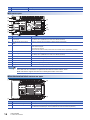
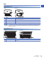
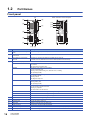
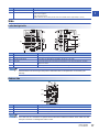
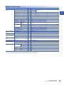


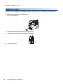
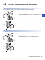
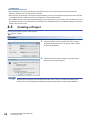
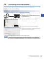
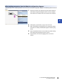

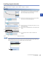
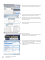

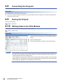
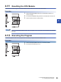
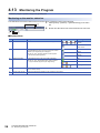

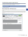
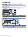
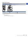


![MELSEC iQ-F FX5U Series User`s Manual [Hardware]](http://vs1.manualzilla.com/store/data/005848866_1-47292304553905fa63d352e8811bb59a-150x150.png)