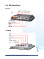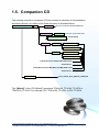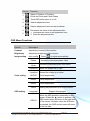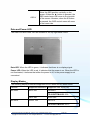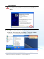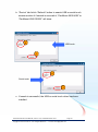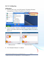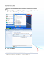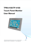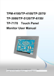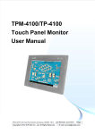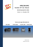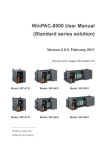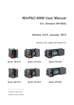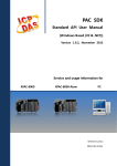
1
TPM-4100/TP-4100/TPM-6 150/TP-6150/TP-2070 Touch Panel Monitor User Manual Touch Panel Monitor User Manual, version 1.0.6, Last Revised: Dec 2013 Copyright © 2012 ICP DAS Co., Ltd. All Rights Reserved. E-mail: [email protected] Page: 1 Warranty All products manufactured by ICP DAS are under warranty regarding defective materials for a period of one year, beginning from the date of delivery to the original purchaser. Warning ICP DAS assumes no liability for any damage resulting from the use of this product. ICP DAS reserves the right to change this manual at any time without notice. The information furnished by ICP DAS is believed to be accurate and reliable. However, no responsibility is assumed by ICP DAS for its use, nor for any infringements of patents or other rights of third parties resulting from its use. Copyright Copyright © 2012 by ICP DAS Co., Ltd. All rights are reserved. Trademarks Names are used for identification purposes only and may be registered trademarks of their respective companies. Contact us If you encounter any problems, please feel free to contact us. You can rely on ICPDAS for a prompt quick response. Email: [email protected] Touch Panel Monitor User Manual, version 1.0.6, Last Revised: Dec 2013 Copyright © 2012 ICP DAS Co., Ltd. All Rights Reserved. E-mail: [email protected] Page: 2 Table of Contents Table of Contents ............................................. 3 1. Introduction .................................................. 5 1.1. Features ..................................................................... 7 1.2. Specifications ............................................................. 8 1.3. Dimension ................................................................ 11 1.4. I/O interfaces............................................................ 19 1.5. Companion CD ........................................................ 22 1.6. System Setup........................................................... 23 1.6.1. System Configuration ................................. 23 1.6.2. Panel Mounting........................................... 28 2. Touch Driver Setup .................................... 30 2.1. Windows CE 5.0 ...................................................... 31 2.1.1. USB Touch Driver ....................................... 32 2.1.1.1. Installation for WinPAC-8000 and WinPAC-5000 33 2.1.1.2. Configuration for WinPAC-8000 and WinPAC-5000 34 2.1.1.3. Uninstalling the WinPAC-8000 and WinPAC-5000 36 2.1.1.4. Other Windows CE5.0 Devices ... 37 2.1.2. Serial Touch Driver ..................................... 38 2.1.2.1. Installation for WinPAC-8000 and WinPAC-5000 39 2.1.2.2. Configuration for WinPAC-8000 and WinPAC-5000 41 2.1.2.3. Uninstalling the WinPAC-8000 and WinPAC-5000 43 2.1.2.4. Other Windows CE5.0 Devices ... 44 2.2. Windows CE 6.0 ...................................................... 45 2.2.1. USB Touch Driver ....................................... 46 2.2.1.1. Installation for XP-8000-CE6 ....... 47 2.2.1.2. Configuration for XP-8000-CE6 ... 49 Touch Panel Monitor User Manual, version 1.0.6, Last Revised: Dec 2013 Copyright © 2012 ICP DAS Co., Ltd. All Rights Reserved. E-mail: [email protected] Page: 3 2.2.1.3. Uninstalling the XP-8000-CE6 ..... 51 2.2.1.4. Other Windows CE6.0 Devices ... 53 2.2.2. Serial Touch Driver ..................................... 54 2.2.2.1. Installation for XP-8000-CE6 ....... 55 2.2.2.2. Configuration for XP-8000-CE6 ... 58 2.2.2.3. Uninstalling the XP-8000-CE6 ..... 60 2.2.2.4. Other Windows CE 6.0 Device .... 62 2.3. Windows XP Embedded .......................................... 63 2.3.1. Universal Driver .......................................... 63 2.3.1.1. Installation for XP-8000 ............... 64 2.3.1.2. Configuration for XP-8000 ........... 70 2.3.1.3. Uninstall for XP-8000 .................. 74 2.3.1.4. Other Windows XP Embedded Devices 76 2.4. Windows XP/7.......................................................... 77 2.4.1. Universal Driver .......................................... 77 2.4.1.1. Installation ................................... 78 2.4.1.2. Configuring .................................. 82 2.4.1.3. Uninstall ...................................... 84 Appendix A. Revision History ....................... 86 Touch Panel Monitor User Manual, version 1.0.6, Last Revised: Dec 2013 Copyright © 2012 ICP DAS Co., Ltd. All Rights Reserved. E-mail: [email protected] Page: 4 1. Introduction This chapter provides an overview of the TPM-4100/TP-4100/TPM-6150 /TP-6150/TP-2070 and its components. Touch Panel Monitor User Manual, version 1.0.6, Last Revised: Dec 2013 Copyright © 2012 ICP DAS Co., Ltd. All Rights Reserved. E-mail: [email protected] Page: 5 The TPM-4100/TP-4100/TPM-6150/TP-6150/TP-2070 Panel Mount Monitor includes a standard TFT LCD screen with a rugged aluminum front bezel resolution and a wide operating temperature range. The TPM-4100/TP-4100/TPM-6150/TP-6150/TP-2070 is also guaranteed to integrate with ICP DAS PAC control systems, such as WP-8000 series and the XP-8000 series. Package List The shipping package includes the following items: 1 TFT LCD Monitor 1 VGA cable 1 RS-232 cable 1 USB cable 4 Mounting clamps 4 Mounting Screws 1 Power supply 1 Companion CD containing software drivers and digital versions of the user manuals Touch Panel Monitor User Manual, version 1.0.6, Last Revised: Dec 2013 Copyright © 2012 ICP DAS Co., Ltd. All Rights Reserved. E-mail: [email protected] Page: 6 1.1. Features Support resolution Mode name Size Resolution 7” 800 x 480 TPM-4100/TP-4100 10.4” 800 x 600 TPM-6150/TP-6150 15” 1024 x 768 TP-2070 Full-function OSD control keys for optimizing the display Driver Support for Windows 2K/XP/Vista/7/XP-Embedded/WinCE 5.0/6.0 Wide operating temperature range Mode name Operating temperature TP-2070 -20~+70 °C TPM-4100/TP-4100 -20~+70 °C TPM-6150/TP-6150 -20~+70 °C Aluminum front bezel design that is ideal for rugged applications LED backlight technology Supports the IP65 standard for protection against dust and water Touch Panel Monitor User Manual, version 1.0.6, Last Revised: Dec 2013 Copyright © 2012 ICP DAS Co., Ltd. All Rights Reserved. E-mail: [email protected] Page: 7 1.2. Specifications The table below is a summary of the specifications of the touch panel, and lists the accessories that are supported by the touch panel. Specifications Model TP-2070 Display Size 7” Resolution 800 x 480 Luminance 400 cd/m2 Touch screen 4-wire, analog resistive; Light Transmission: 80% Contrast ratio 500:1 Viewing angle (H/V) 140/120 Backlight life (hrs) 20,000 Touchscreen function Input signal Combo RS-232 & USB interface VGA (analog RGB) MMI (Man Machine Interface) OSD control Functions: Brightness, Contrast, Clock, Phase, Horizontal Position, Vertical Position and Sharpness Power switch Yes LED indicators Power, Display signal is detected Power Input range +12 ~ +48 VDC Power consumption 5W Mechanical Casing Dimensions (W x L x H) Installation Ingress protection Plastic 213 mm x 148 mm x 44 mm Panel Mounting, VESA (75 x 75) Mounting Front panel: IP65 Environmental Operating temperature -20 ~ +70℃ Storage temperature -30 ~ +80℃ Ambient relative humidity 10 ~ 90% RH (non-condensing) Touch Panel Monitor User Manual, version 1.0.6, Last Revised: Dec 2013 Copyright © 2012 ICP DAS Co., Ltd. All Rights Reserved. E-mail: [email protected] Page: 8 Model TPM-4100 TP-4100 Display Size 10.4” Resolution 800 x 600 Max. colors 16.7 M Luminance Touch screen 400 cd/m2 5-wire, analog resistive Light Transmission: 80% 4-wire, analog resistive Light Transmission: 80% Contrast ratio 500:1 Viewing angle (H/V) 140/130 Backlight life (hrs) 50,000 Touchscreen function Combo RS-232 & USB interface Input signal VGA (analog RGB) MMI (Man Machine Interface) OSD control Functions: Brightness, Contrast, Clock, Phase, Horizontal Position, Vertical Position and Sharpness Power switch Yes LED indicators Power, Display signal is detected Power Input range +12 ~ +48 VDC Power consumption 8.5 W Mechanical Material Dimensions (W x L x H) Installation Ingress protection Aluminum Plastic 293 mm x 231 mm x 53 mm 291 mm x 229 mm x 54 mm Panel Mounting Panel Mounting, VESA (75 x 75) Mounting Front panel: IP65 Environmental Operating temperature -20 ~ +70℃ Storage temperature -30 ~ +80℃ Ambient relative humidity 10 ~ 90% RH (non-condensing) Touch Panel Monitor User Manual, version 1.0.6, Last Revised: Dec 2013 Copyright © 2012 ICP DAS Co., Ltd. All Rights Reserved. E-mail: [email protected] Page: 9 Model TPM-6150 TP-6150 Display Size 15” Resolution 1024 x 768 Max. colors 16.7 M Luminance 400 cd/m2 Touch screen 5-wire, analog resistive Light Transmission: 80% Contrast ratio 500:1 Viewing angle (H/V) 140/130 Backlight life (hrs) 50,000 Touchscreen function Combo RS-232 & USB interface Input signal VGA (analog RGB) MMI (Man Machine Interface) OSD control Functions: Brightness, Contrast, Phase, Horizontal Position, Vertical Position Power switch Yes LED indicators Power, Display signal is detected Power Input range +12 ~ +48 VDC Power consumption 14.4 W Mechanical Material Dimensions (W x L x H) Installation Ingress protection Aluminum Plastic 379 mm x 304 mm x 58 mm 381 mm x 305 mm x 65 mm Panel Mounting VESA (75mm x 75mm; 100mm x 100mm) Mounting Front panel: IP65 Environmental Operating temperature -20 ~ +70℃ Storage temperature -30 ~ +80℃ Ambient relative humidity 10 ~ 90% RH (non-condensing) Touch Panel Monitor User Manual, version 1.0.6, Last Revised: Dec 2013 Copyright © 2012 ICP DAS Co., Ltd. All Rights Reserved. E-mail: [email protected] Page: 10 1.3. Dimension TP-2070 (Unit: mm) Touch Panel Monitor User Manual, version 1.0.6, Last Revised: Dec 2013 Copyright © 2012 ICP DAS Co., Ltd. All Rights Reserved. E-mail: [email protected] Page: 11 Touch Panel Monitor User Manual, version 1.0.6, Last Revised: Dec 2013 Copyright © 2012 ICP DAS Co., Ltd. All Rights Reserved. E-mail: [email protected] Page: 12 TPM-4100 (Unit: mm) Touch Panel Monitor User Manual, version 1.0.6, Last Revised: Dec 2013 Copyright © 2012 ICP DAS Co., Ltd. All Rights Reserved. E-mail: [email protected] Page: 13 Touch Panel Monitor User Manual, version 1.0.6, Last Revised: Dec 2013 Copyright © 2012 ICP DAS Co., Ltd. All Rights Reserved. E-mail: [email protected] Page: 14 TP-4100 (Unit: mm) Touch Panel Monitor User Manual, version 1.0.6, Last Revised: Dec 2013 Copyright © 2012 ICP DAS Co., Ltd. All Rights Reserved. E-mail: [email protected] Page: 15 Touch Panel Monitor User Manual, version 1.0.6, Last Revised: Dec 2013 Copyright © 2012 ICP DAS Co., Ltd. All Rights Reserved. E-mail: [email protected] Page: 16 TP-6150 (Unit: mm) Touch Panel Monitor User Manual, version 1.0.6, Last Revised: Dec 2013 Copyright © 2012 ICP DAS Co., Ltd. All Rights Reserved. E-mail: [email protected] Page: 17 TPM-6150 (Unit: mm) Available soon. Under construction Touch Panel Monitor User Manual, version 1.0.6, Last Revised: Dec 2013 Copyright © 2012 ICP DAS Co., Ltd. All Rights Reserved. E-mail: [email protected] Page: 18 1.4. I/O interfaces TP-2070 TPM-4100 Touch Panel Monitor User Manual, version 1.0.6, Last Revised: Dec 2013 Copyright © 2012 ICP DAS Co., Ltd. All Rights Reserved. E-mail: [email protected] Page: 19 TP-4100 TP-6150 Touch Panel Monitor User Manual, version 1.0.6, Last Revised: Dec 2013 Copyright © 2012 ICP DAS Co., Ltd. All Rights Reserved. E-mail: [email protected] Page: 20 TPM-6150 Under construction Touch Panel Monitor User Manual, version 1.0.6, Last Revised: Dec 2013 Copyright © 2012 ICP DAS Co., Ltd. All Rights Reserved. E-mail: [email protected] Page: 21 1.5. Companion CD This package includes a companion CD that contains a collection of documentation and device drivers. An outline of the folder structure is illustrated below. CD:\[Model] Driver Win_XP_7 Win_XP_Embedded Touch Driver for Windows 2K/XP/2003/2008/Vista/7 XP-8000 device Touch Driver for the XP-8000 series Other XP Embedded device WinCE V5.0 Touch Driver Other CE5.0 device WP-8000 and WP-5000 device V6.0 Other CE6.0 device XP-8000-CE6 device Touch Driver for the XP-8000-CE6 series Touch Driver Touch Driver for the WP-8000 and WP-5000 series Touch Driver Documents Touch_Panel_User_Manual_vXXX.pdf The “[Model]” of the “CD:\[Model]” represents TPM-4100_TP-4100, TP-2070 or TPM-6150_TP-6150. For example, CD:\ TPM-4100_TP-4100, or CD:\ TP-2070. Touch Panel Monitor User Manual, version 1.0.6, Last Revised: Dec 2013 Copyright © 2012 ICP DAS Co., Ltd. All Rights Reserved. E-mail: [email protected] Page: 22 1.6. System Setup This section gives details regarding system configuration and adjustment and mounting options. 1.6.1. System Configuration Front Panel Controls TPM-4100 TP-2070 TP-4100 TP-6150 TPM-6150 Under construction Touch Panel Monitor User Manual, version 1.0.6, Last Revised: Dec 2013 Copyright © 2012 ICP DAS Co., Ltd. All Rights Reserved. E-mail: [email protected] Page: 23 Control 1 Function Adjust V-Position, H-Position, Clock and Clock and Clock-Phase 2 Turns OSD main menu on or off 3 Selects adjustment item 4 Selects adjustment item counter-clockwise 5 Decreases the value of the adjustment item 1. Increases the value of the adjustment item 2. Enter the adjustment item 6 OSD Menu Functions Control Description Contrast Adjusts the contrast of the monitor Brightness Adjusts the brightness of the monitor Image setting Auto config Color setting OSD setting Press to adjust automatically Phase Increase or decrease phase value. Clock Increase or decrease pixel clock value H-position Move the screen left or right V-position Moves the screen up or down NATIVE Color temperature 9300K Color temperature 6500K Color temperature USER Making adjustments to the R/G/B content. Language Support 8 languages. OSD.H Move the OSD position horizontally on the screen. When the ▲ button is pressed, the OSD control menu will move to the right side of the screen. Likewise, when the ▼ button is pressed, the OSD control menu will move to the left side. Touch Panel Monitor User Manual, version 1.0.6, Last Revised: Dec 2013 Copyright © 2012 ICP DAS Co., Ltd. All Rights Reserved. E-mail: [email protected] Page: 24 OSD.V Move the OSD position vertically on the screen. When the ▲ button is pressed, the OSD control menu will move to the top side of the screen. Likewise, when the ▼ button is pressed, the OSD control menu will move to the lower side. Data and Power LED The Data LED and Power LED are situated in the top right-hand corner. Data LED: When the LED is green, it indicates that there is no display signal. Power LED: When the LED is red, it indicates that the power is on. When the LED is not illuminated, it indicates that either the power is off, or the power supply is not connected. Display Modes__ The following display modes are supported for WP-8000 and XP-8000 series. Platform Supported Resolution Supported Vert. Sync.(Hz) WP-8x4x 800 x 600 55.8/56.6 TP-6150/TPM-6150: 55.8 WP-8x3x 640 x 480 Don’t care 1024 x 768 60/70/75 TP-6150/TPM-6150: 60/75 Touch Panel Monitor User Manual, version 1.0.6, Last Revised: Dec 2013 Copyright © 2012 ICP DAS Co., Ltd. All Rights Reserved. E-mail: [email protected] Page: 25 800 x 600 60/72/75 TP-6150/TPM-6150: 60/72 640 x 480 56/60/62/70/72/75 TP-6150/TPM-6150: 72 WP-8x5x XP-8x4x-Atom XP-8x4x-Atom-CE6 XP-8x4x XP-8x4x-CE6 800 x 600 55.8/56.6 640 x 480 Don’t care 1280 x 720 Don’t care 1024 x 768 Don’t care 800 x 600 Don’t care 1024 x 768 60/70/75/85 800 x 600 60/70/75/85 640 x 480 60/70/75/85 1024 x 768 Don’t care 800 x 600 Don’t care 1290 x 1024 TP-2070: not support TP-4100/TPM-4100: 60/70/75 1152 x 864 TP-2070: 70/75 TP-4100/TPM-4100: 60/70/75 1024 x 768 60/70/75 800 x 600 60/70/75 640 x 480 60/70/75 The following display modes are supported for other devices. Resolution Horiz. Sync. Vert. Sync. 640 x 480 31.4 KHz 50 Hz 31.4 KHz 59.9 Hz 37.5 KHz 75 Hz 720 x 400 31.4 KHz 70 Hz 800 x 600 35.1 KHz 56.2 Hz Touch Panel Monitor User Manual, version 1.0.6, Last Revised: Dec 2013 Copyright © 2012 ICP DAS Co., Ltd. All Rights Reserved. E-mail: [email protected] Page: 26 1024 x 768 37.8 KHz 60.3 Hz 46.9 KHz 75 Hz 48.3 KHz 60 Hz 56.4 KHz 70 Hz 60.0 KHz 75 Hz Touch Panel Monitor User Manual, version 1.0.6, Last Revised: Dec 2013 Copyright © 2012 ICP DAS Co., Ltd. All Rights Reserved. E-mail: [email protected] Page: 27 1.6.2. Panel Mounting Insert the mounting brackets. Screw the mounting bracket to the unit. Eight locations are available for attaching four mounting clamps to secure the unit. Touch Panel Monitor User Manual, version 1.0.6, Last Revised: Dec 2013 Copyright © 2012 ICP DAS Co., Ltd. All Rights Reserved. E-mail: [email protected] Page: 28 Panel thickness up to 6 mm. Refer to Sec.1.3 for default information regarding the dimensions of the panel. Touch Panel Monitor User Manual, version 1.0.6, Last Revised: Dec 2013 Copyright © 2012 ICP DAS Co., Ltd. All Rights Reserved. E-mail: [email protected] Page: 29 2. Touch Driver Setup This chapter provides a overview that describes the steps required for installing, uninstalling, and configuring the touch driver. Touch Panel Monitor User Manual, version 1.0.6, Last Revised: Dec 2013 Copyright © 2012 ICP DAS Co., Ltd. All Rights Reserved. E-mail: [email protected] Page: 30 2.1. Windows CE 5.0 This section describes how to install, calibrate and uninstall the touch driver for the WP-8000 series and WP-5000 series, and gives details of how to obtain drivers for other CE5 devices. Touch Panel Monitor User Manual, version 1.0.6, Last Revised: Dec 2013 Copyright © 2012 ICP DAS Co., Ltd. All Rights Reserved. E-mail: [email protected] Page: 31 2.1.1. USB Touch Driver Two USB touch drivers are available. The first is for WP-8000 series modules and WP-5000 series modules of ICP DAS PAC controllers, and the second is for other Windows CE5.0 systems. WP-8000 series: WP-8131/WP-8431/WP-8831, WP-8141/WP-8441/WP-8841 WP-8137/WP-8437/WP-8837, WP-8147/WP-8447/WP-8847 WP-8139/WP-8431/WP-8839, WP-8141/WP-8441/WP-8849 WP-8136/WP-8431/WP-8836, WP-8141/WP-8441/WP-8846 WP-5000 series: WP-5141/WP-5441-OD/WP-5149/WP-5449-OD/WP-5147/WP-5447-OD/ WP-5146/WP-5446-OD Touch Panel Monitor User Manual, version 1.0.6, Last Revised: Dec 2013 Copyright © 2012 ICP DAS Co., Ltd. All Rights Reserved. E-mail: [email protected] Page: 32 2.1.1.1. Installation for WinPAC-8000 and WinPAC-5000 The following procedure describes how to install the PenMount USB touch driver. 1. Copy the driver from the CD-ROM to the WinPAC. The “PenMount_USB_TOUCH_Vyyyymmdd.CAB” driver file can be obtained from: Model Driver path TP-2070 CD:\TP-2070 \Driver\WinCE\V5.0\WP-8000 and WP-5000 device TPM-4100/TP-4100 CD:\TPM-4100_TP-4100\Driver\WinCE\V5.0\WP-8000 and WP-5000 device\ TPM-6150/TP-6150 CD:\TPM-6150_TP-6150 \Driver\WinCE\V5.0\WP-8000 and WP-5000 device Or go to the “\System_Disk\External_device_driver\” folder on the WinPAC. 2. Double-click the “PenMount_USB_TOUCH_Vyyyymmdd.CAB” file. 3. Show one of two dialogs below. Just click the “OK” button to continue installation. Click ”OK” Or 4. From the “Start” menu, click ”Programs”Open the “WinPAC Utility”, and then click the “Save and Reboot” option from the “File” menu. Touch Panel Monitor User Manual, version 1.0.6, Last Revised: Dec 2013 Copyright © 2012 ICP DAS Co., Ltd. All Rights Reserved. E-mail: [email protected] Page: 33 2.1.1.2. Configuration for WinPAC-8000 and WinPAC-5000 Calibration 1. From the “Start” menu, click “Programs””USB_TOUCH” ”PenMount””Calibration”. 2. Follow the instructions on the screen to begin calibration. 3. Once calibration has been completed, from the “Start” menu, click ”Programs”Open the “WinPAC Utility”, and then click the “Save and Reboot” option from the “File” menu. Touch Panel Monitor User Manual, version 1.0.6, Last Revised: Dec 2013 Copyright © 2012 ICP DAS Co., Ltd. All Rights Reserved. E-mail: [email protected] Page: 34 Simulating the Right Mouse Button 1. From the Start menu, click “Programs””USB_TOUCH” ”PenMount””RightButton”. 2. Show a screen below (Left picture) Click the “mouse” Turn into right picture. Click the “mouse” 3. Become Click any object: Click “My device” to test if the function of “RightButton” works. If the screen below shows, the function of “RightButton” works. 4. The operation of the right mouse button can be simulated by repeating Step 2 and Step 3 for any object. Touch Panel Monitor User Manual, version 1.0.6, Last Revised: Dec 2013 Copyright © 2012 ICP DAS Co., Ltd. All Rights Reserved. E-mail: [email protected] Page: 35 2.1.1.3. Uninstalling the WinPAC-8000 and WinPAC-5000 The following procedure describes how to uninstall the PenMount USB touch driver. 1. From the “Start” menu, click “Programs””USB_TOUCH” ”PenMount””Uninstall”. 2. A warning pop-up will be displayed asking you to confirm the uninstall request. Click the “Yes” button to uninstall the driver. 3. Once the uninstallation process is complete, a dialog will displayed requesting that you reboot the system. Click the “Yes” button to reboot the WinPAC immediately, or click “NO” if you intend to reboot at a later time. Touch Panel Monitor User Manual, version 1.0.6, Last Revised: Dec 2013 Copyright © 2012 ICP DAS Co., Ltd. All Rights Reserved. E-mail: [email protected] Page: 36 2.1.1.4. Other Windows CE5.0 Devices The driver for use with other windows CE5.0 devices can be obtained from: Model Driver path TP-2070 CD:\TP-2070 \Driver\WinCE\V5.0\Other CE5.0 device TPM-4100/TP-4100 CD:\TPM-4100_TP-4100\Driver\WinCE\V5.0\Other CE5.0 device\ TPM-6150/TP-6150 CD:\TPM-6150_TP-6150 \Driver\WinCE\V5.0\Other CE5.0 device or go to the PenMount website to download the latest driver: http://www.penmount.com/down_2_1.php Touch Panel Monitor User Manual, version 1.0.6, Last Revised: Dec 2013 Copyright © 2012 ICP DAS Co., Ltd. All Rights Reserved. E-mail: [email protected] Page: 37 2.1.2. Serial Touch Driver Two serial touch drivers are available. The first is for WP-8000 series modules and WP-5000 series modules of ICPDAS PAC controllers, and the second is for other Windows CE5.0 systems. WP-8000 series: WP-8131/WP-8431/WP-8831, WP-8141/WP-8441/WP-8841 WP-8137/WP-8437/WP-8837, WP-8147/WP-8447/WP-8847 WP-8139/WP-8431/WP-8839, WP-8141/WP-8441/WP-8849 WP-8136/WP-8431/WP-8836, WP-8141/WP-8441/WP-8846 WP-5000 series: WP-5141/WP-5441-OD/WP-5149/WP-5449-OD/WP-5147/WP-5447-OD/ WP-5146/WP-5446-OD Touch Panel Monitor User Manual, version 1.0.6, Last Revised: Dec 2013 Copyright © 2012 ICP DAS Co., Ltd. All Rights Reserved. E-mail: [email protected] Page: 38 2.1.2.1. Installation for WinPAC-8000 and WinPAC-5000 The following procedure describes how to install the PenMount serial touch driver. Note that the default COM port for serial touch driver is COM4. There is a RS-232 cable in the shipping package (Sec.1). The user can directly use this cable to connect the monitor with COM4 of WinPAC-8000 to use serial touch driver to do a touch operation by serial way. If the user wants to use other com port, please note the position of TX and RX of COM port. About the pin assignment, please refer to the user manual of the WinPAC-8000 COM4 Warning: The WinPAC-5000 series doesn’t include a COM4, so please refer to “Changing the COM Port” in Sec.2.1.2.2 for details of how to change the COM Port to the specified COM Port. 1. Copy the driver from the CD-ROM to the WinPAC. The “PenMount_Serial_TOUCH_Vyyyymmdd(PM6000R).CAB” driver file can be obtained from: Touch Panel Monitor User Manual, version 1.0.6, Last Revised: Dec 2013 Copyright © 2012 ICP DAS Co., Ltd. All Rights Reserved. E-mail: [email protected] Page: 39 Model Driver path TP-2070 CD:\TP-2070 \Driver\WinCE\V5.0\WP-8000 and WP-5000 device TPM-4100/TP-4100 CD:\TPM-4100_TP-4100\Driver\WinCE\V5.0\WP-8000 and WP-5000 device\ TPM-6150/TP-6150 CD:\TPM-6150_TP-6150 \Driver\WinCE\V5.0\WP-8000 and WP-5000 device Or go to the “\System_Disk\External_device_driver\” folder on the WinPAC. 2. Double-click the “PenMount_Serial_TOUCH_Vyyyymmdd(PM6000R).CAB” file. 3. Show one of two dialogs below. Just click “OK” button to continue installation. Click “OK” button Or 4. From the “Start” menu, click ”Programs”Open the “WinPAC Utility”, and then click the “Save and Reboot” option from the “File” menu. Touch Panel Monitor User Manual, version 1.0.6, Last Revised: Dec 2013 Copyright © 2012 ICP DAS Co., Ltd. All Rights Reserved. E-mail: [email protected] Page: 40 2.1.2.2. Configuration for WinPAC-8000 and WinPAC-5000 Calibration 1. From the “Start” menu, click “Programs””Serial_TOUCH” ”PenMount””Calibration”. 2. Follow the instruction on the screen to begin calibration. 3. Once calibration has been completed, from the “Start” menu, click ”Programs”Open the “WinPAC Utility”, and then click the “Save and Reboot” option from the “File” menu. Touch Panel Monitor User Manual, version 1.0.6, Last Revised: Dec 2013 Copyright © 2012 ICP DAS Co., Ltd. All Rights Reserved. E-mail: [email protected] Page: 41 Changing the COM Port 1. From the “Start” menu, click “Programs””Serial_TOUCH” ”PenMount””SetCOM”. 2. In the pop-up dialog, select the COM Port you wish to use as default and click the “Set” button to save the changes. 3. From the “Start” menu, click ”Programs”Open the “WinPAC Utility”, and then click the “Save and Reboot” option from the “File” menu. 4. Disconnect the cable from the current COM Port and reconnect it to the specified COM Port. Simulating the Right Mouse Button For details of how to configure right mouse button simulation, please refer to the process describes in “Simulating the Right Mouse Button” in Sec.2.1.1.2 Touch Panel Monitor User Manual, version 1.0.6, Last Revised: Dec 2013 Copyright © 2012 ICP DAS Co., Ltd. All Rights Reserved. E-mail: [email protected] Page: 42 2.1.2.3. Uninstalling the WinPAC-8000 and WinPAC-5000 The following procedure describes how to uninstall the PenMount serial touch driver. 1. From the “Start” menu, click “Programs””Serial_TOUCH” ”PenMount””Uninstall” 2. A warning pop-up will be displayed asking you to confirm the uninstall request. Click the “Yes” button to uninstall the driver. 3. Once the uninstallation process is complete, a dialog will displayed requesting that you reboot the system. Click the “Yes” button to reboot the WinPAC immediately, or click “NO” if you intend to reboot at a later time. Touch Panel Monitor User Manual, version 1.0.6, Last Revised: Dec 2013 Copyright © 2012 ICP DAS Co., Ltd. All Rights Reserved. E-mail: [email protected] Page: 43 2.1.2.4. Other Windows CE5.0 Devices The driver can be obtained from: Model Driver path TP-2070 CD:\TP-2070 \Driver\WinCE\V5.0\Other CE5.0 device TPM-4100/TP-4100 CD:\TPM-4100_TP-4100\Driver\WinCE\V5.0\Other CE5.0 device\ TPM-6150/TP-6150 CD:\TPM-6150_TP-6150 \Driver\WinCE\V5.0\Other CE5.0 device or go to PenMount website to download the latest driver: http://www.penmount.com/down_2_1.php Touch Panel Monitor User Manual, version 1.0.6, Last Revised: Dec 2013 Copyright © 2012 ICP DAS Co., Ltd. All Rights Reserved. E-mail: [email protected] Page: 44 2.2. Windows CE 6.0 This section describes how to install, calibrate and uninstall the touch driver for the XP-8000-CE6 series, and gives details of how to obtain drivers for other CE6 devices. Touch Panel Monitor User Manual, version 1.0.6, Last Revised: Dec 2013 Copyright © 2012 ICP DAS Co., Ltd. All Rights Reserved. E-mail: [email protected] Page: 45 2.2.1. USB Touch Driver Two USB touch drivers are available. The first is for XP-8000-CE6 series modules of ICP DAS PAC controllers and, and the second is for other Windows CE6.0 systems. XP-8000-CE6 series: 1. Using the ATOM CPU: XP-8141-Atom-CE6/XP-8341-Atom-CE6/XP-8741-Atom-CE6 XP-8147-Atom-CE6/XP-8347-Atom-CE6/XP-8747-Atom-CE6 XP-8149-Atom-CE6/XP-8349-Atom-CE6/XP-8749-Atom-CE6 2. Using the LX800 CPU: XP-8041-CE6/XP-8341-CE6/XP-8741-CE6 XP-8047-CE6/XP-8347-CE6/XP-8747-CE6 XP-8049-CE6/XP-8349-CE6/XP-8749-CE6 XP-8046-CE6/XP-8346-CE6/XP-8746-CE6 Touch Panel Monitor User Manual, version 1.0.6, Last Revised: Dec 2013 Copyright © 2012 ICP DAS Co., Ltd. All Rights Reserved. E-mail: [email protected] Page: 46 2.2.1.1. Installation for XP-8000-CE6 The following procedure describes how to install the PenMount USB touch driver. 1. Copy the driver from the CD-ROM to the XP-8000-CE6. The “PenMount_USB_TOUCH_Vxx_yyyymmdd_XPAC_CE6.CAB” driver file can be obtained from: Model Driver path TP-2070 CD:\TP-2070\Driver\WinCE\V6.0\XP-8000-CE6 device\ TPM-4100/TP-4100 CD:\TPM-4100_TP-4100\Driver\WinCE\V6.0\XP-8000-CE6 device\ TPM-6150/TP-6150 CD:\TPM-6150_TP-6150\Driver\WinCE\V6.0\XP-8000-CE6 device\ Or go to the “\System_Disk\External_device_driver” folder on the XP-8000-CE6. 2. Double-click the “PenMount_USB_TOUCH_Vxx_yyyymmdd_XPAC_CE6.CAB” file. Tips & Warnings The driver (*.cab) file can only be used once. If you attempt to use it to install driver a second time, a warning dialog with a message similar to “<FileName> is not a valid Windows CE Setup file” will be displayed advising that the setup has failed. Please re-download a new (*.cab) file to use. 3. Depending on the type of CPU, one of two dialog windows will be displayed. Click the “OK” button to continue with the installation. Touch Panel Monitor User Manual, version 1.0.6, Last Revised: Dec 2013 Copyright © 2012 ICP DAS Co., Ltd. All Rights Reserved. E-mail: [email protected] Page: 47 Using the ATOM CPU Using the LX800 CPU Or 4. Once the installation has been completed, a dialog will be displayed advising that the system needs to be rebooted. Click the “OK” button to reboot the XP-8000-CE6. Touch Panel Monitor User Manual, version 1.0.6, Last Revised: Dec 2013 Copyright © 2012 ICP DAS Co., Ltd. All Rights Reserved. E-mail: [email protected] Page: 48 2.2.1.2. Configuration for XP-8000-CE6 Calibration 1. From the “Start” menu, click “Programs””USB_TOUCH” ”PenMount””Calibration”. 2. Following the instructions on the screen to begin calibration. Touch Panel Monitor User Manual, version 1.0.6, Last Revised: Dec 2013 Copyright © 2012 ICP DAS Co., Ltd. All Rights Reserved. E-mail: [email protected] Page: 49 Simulating the Right Mouse Button For details of how to simulate right mouse button functions, please refer to the process described in “Simulating the Right Mouse Button” in Sec. 2.1.1.2 Touch Panel Monitor User Manual, version 1.0.6, Last Revised: Dec 2013 Copyright © 2012 ICP DAS Co., Ltd. All Rights Reserved. E-mail: [email protected] Page: 50 2.2.1.3. Uninstalling the XP-8000-CE6 The following procedure describes how to uninstall the PenMount USB touch driver. 1. From the “Start” menu, click “Settings””Control Panel”. 2. Double click the “Remove Programs” icon and select “ICPDAS USB PenMount” from the “Programs” panel in the “Remove Programs” dialog box and then click the “Remove” button. When the warning pop-up, click “Yes” button to permanently uninstall the driver. 1 2 3 4 Touch Panel Monitor User Manual, version 1.0.6, Last Revised: Dec 2013 Copyright © 2012 ICP DAS Co., Ltd. All Rights Reserved. E-mail: [email protected] Page: 51 3. Once the uninstallation process is complete, a dialog will be displayed requesting that you reboot the system. Click the “Yes” button to reboot immediately or click the “No” button if you intend to reboot at a later time. Touch Panel Monitor User Manual, version 1.0.6, Last Revised: Dec 2013 Copyright © 2012 ICP DAS Co., Ltd. All Rights Reserved. E-mail: [email protected] Page: 52 2.2.1.4. Other Windows CE6.0 Devices The driver can be obtained from: Model Driver path TP-2070 CD:\TP-2070\Driver\WinCE\V6.0\Other CE6.0 device\ TPM-4100/TP-4100 CD:\TPM-4100_TP-4100\Driver\WinCE\V6.0\Other CE6.0 device\ TPM-6150/TP-6150 CD:\TPM-6150_TP-6150\Driver\WinCE\V6.0\Other CE6.0 device\ or go to the PenMount website to download the latest driver: http://www.penmount.com/down_2_1.php Touch Panel Monitor User Manual, version 1.0.6, Last Revised: Dec 2013 Copyright © 2012 ICP DAS Co., Ltd. All Rights Reserved. E-mail: [email protected] Page: 53 2.2.2. Serial Touch Driver Two serial touch drivers are available. The first is for XP-8000-CE6 series modules of ICPDAS PAC controllers and the second is for other Windows CE6.0 systems. XP-8000-CE6 series: 1.Using ATOM CPU XP-8141-Atom-CE6/XP-8341-Atom-CE6/XP-8741-Atom-CE6 XP-8147-Atom-CE6/XP-8347-Atom-CE6/XP-8747-Atom-CE6 XP-8149-Atom-CE6/XP-8349-Atom-CE6/XP-8749-Atom-CE6 2.Using LX800 CPU XP-8041-CE6/XP-8341-CE6/XP-8741-CE6 XP-8047-CE6/XP-8347-CE6/XP-8747-CE6 XP-8049-CE6/XP-8349-CE6/XP-8749-CE6 XP-8046-CE6/XP-8346-CE6/XP-8746-CE6 Touch Panel Monitor User Manual, version 1.0.6, Last Revised: Dec 2013 Copyright © 2012 ICP DAS Co., Ltd. All Rights Reserved. E-mail: [email protected] Page: 54 2.2.2.1. Installation for XP-8000-CE6 The following procedure describes how to install the PenMount Serial touch driver. Note that the default COM Port for the touch driver is COM5. There is a RS-232 cable in the shipping package (Sec.1). The user can directly use this cable to connect the monitor with COM5 of XP-8000-CE6 to use serial touch driver to do a touch operation by serial way. If the user wants to use other com port, please note the position of TX and RX of COM port. About the pin assignment, please refer to the user manual of the XP-8000-CE6 COM5 1. Copy the driver from the CD-ROM to the XP-8000-CE6 device. The “PenMount_Serial_TOUCH_Vxx_yyyymmdd_XPAC_CE6(PM6000R).CAB” file can be obtained from: Model Driver path TP-2070 CD:\TP-2070\Driver\WinCE\V6.0\XP-8000-CE6 device\ TPM-4100/TP-4100 CD:\TPM-4100_TP-4100\Driver\WinCE\V6.0\XP-8000-CE6 device\ Touch Panel Monitor User Manual, version 1.0.6, Last Revised: Dec 2013 Copyright © 2012 ICP DAS Co., Ltd. All Rights Reserved. E-mail: [email protected] Page: 55 TPM-6150/TP-6150 CD:\TPM-6150_TP-6150\Driver\WinCE\V6.0\XP-8000-CE6 device\ Or go to the “\System_Disk\External_device_driver” folder on the XP-8000-CE6. 2. Double click the “PenMount_Serial_TOUCH_Vxx_yyyymmdd_XPAC_CE6(PM6000R).CAB” file. Tips & Warnings The driver (*.cab) file can only be used once. If you attempt to use it to install driver a second time, a warning dialog with a message similar to “<filename>is not a valid Windows CE Setup file” will be displayed advising that the setting has failed. Please re-download a new (*.cab) file to use. 3. Depending on the type of CPU, one of two dialog windows will be displayed. If the controller use the ATOM CPU, the following will be displayed. Alternatively, if the controller use the LX800 CPU, the following will be displayed. Or Click the “OK” button to continue with the installation. Touch Panel Monitor User Manual, version 1.0.6, Last Revised: Dec 2013 Copyright © 2012 ICP DAS Co., Ltd. All Rights Reserved. E-mail: [email protected] Page: 56 4. Once the installation has been completed, a dialog will be displayed advising that the system needs to be rebooted. Click the “OK” button to reboot the XP-8000-CE6. Touch Panel Monitor User Manual, version 1.0.6, Last Revised: Dec 2013 Copyright © 2012 ICP DAS Co., Ltd. All Rights Reserved. E-mail: [email protected] Page: 57 2.2.2.2. Configuration for XP-8000-CE6 Calibration 1. From the “Start” menu, click “Programs””Serial_TOUCH” ”PenMount””Calibration” 2. Follow the instruction on the screen to begin calibration. You will be presented with one of two screens depending on the CPU you are using. If you are using the LX800 CPU, the screen will look like this. If you are using the ATOM CPU, the screen will look like this. Touch Panel Monitor User Manual, version 1.0.6, Last Revised: Dec 2013 Copyright © 2012 ICP DAS Co., Ltd. All Rights Reserved. E-mail: [email protected] Page: 58 Change the COM Port 1. From the “Start” menu, click “Programs””Serial_TOUCH” ”PenMount””SetCOM”. 2. Just choose the COM portClick “Set” buttonClick “Yes” button to reboot the system. The baudrate for the touch monitor is 19200 bps, so please don’t modify the baudrate of touch driver. 1 2 3 Simulating Right Mouse Button For details of how to configure right mouse button simulation, please refer to the process describes in “Simulating the Right Mouse Button” in Sec.2.1.1.2 Touch Panel Monitor User Manual, version 1.0.6, Last Revised: Dec 2013 Copyright © 2012 ICP DAS Co., Ltd. All Rights Reserved. E-mail: [email protected] Page: 59 2.2.2.3. Uninstalling the XP-8000-CE6 The following procedure describes how to uninstall the PenMount serial touch driver. 1. From the “Start” menu, click “Settings””Control Panel”. 2. Double click the “Remove Programs” icon and select “ICPDAS Serial PenMount” from the “Programs” panel in the “Remove Programs” dialog box and then click the “Remove” button. When the warning pop-up, click “Yes” button to permanently uninstall the driver. 1 2 3 4 Touch Panel Monitor User Manual, version 1.0.6, Last Revised: Dec 2013 Copyright © 2012 ICP DAS Co., Ltd. All Rights Reserved. E-mail: [email protected] Page: 60 3. Once the uninstallation process is complete, a dialog will be displayed requesting that you reboot the system. Click the “Yes” button to reboot immediately or click the “No” button if you intend to reboot at a later. Touch Panel Monitor User Manual, version 1.0.6, Last Revised: Dec 2013 Copyright © 2012 ICP DAS Co., Ltd. All Rights Reserved. E-mail: [email protected] Page: 61 2.2.2.4. Other Windows CE 6.0 Device The driver can be obtained from: Model Driver path TP-2070 CD:\TP-2070\Driver\WinCE\V6.0\Other CE6.0 device\ TPM-4100/TP-4100 CD:\TPM-4100_TP-4100\Driver\WinCE\V6.0\Other CE6.0 device\ TPM-6150/TP-6150 CD:\TPM-6150_TP-6150\Driver\WinCE\V6.0\Other CE6.0 device\ or go to the PenMount website to download the latest driver: http://www.penmount.com/down_2_1.php Touch Panel Monitor User Manual, version 1.0.6, Last Revised: Dec 2013 Copyright © 2012 ICP DAS Co., Ltd. All Rights Reserved. E-mail: [email protected] Page: 62 2.3. Windows XP Embedded The touch driver for XP embedded is a universal driver. USB and Serial both use the same driver. 2.3.1. Universal Driver Two universal touch drivers are available. The first is for XP-8000 series modules of ICP DAS PAC controller, and the second is for other Windows XP embedded system. XP-8000 series: 1.Using ATOM CPU XP-8141-Atom/XP-8341-Atom/XP-8741-Atom 2. Using LX800 CPU XP-8041/XP-8341/XP-8741 Touch Panel Monitor User Manual, version 1.0.6, Last Revised: Dec 2013 Copyright © 2012 ICP DAS Co., Ltd. All Rights Reserved. E-mail: [email protected] Page: 63 2.3.1.1. Installation for XP-8000 The following procedure describes how to install the PenMount universal touch driver. There is a RS-232 cable in the shipping package (Sec.1). The user can directly use this cable to connect the monitor with COM5 of XP-8000 to use universal touch driver to do a touch operation by serial way. If the user wants to use other com port, please note the position of TX and RX of COM port. About the pin assignment, please refer to the user manual of the XP-8000. COM5 1. Copy the driver from the CD-ROM to the XP-8000. The “PenMount Windows Universal Driver Vx.x.x.x” folder can be obtained from: Model Driver path TP-2070 CD:\TP-2070\Driver\Win_XP_Embedded\XP-8000 device\ Touch Panel Monitor User Manual, version 1.0.6, Last Revised: Dec 2013 Copyright © 2012 ICP DAS Co., Ltd. All Rights Reserved. E-mail: [email protected] Page: 64 2. TPM-4100/TP-4100 CD:\TPM-4100_TP-4100\Driver\Win_XP_Embedded\XP-8000 device\ TPM-6150/TP-6150 CD:\TPM-6150_TP-6150\Driver\Win_XP_Embedded\XP-8000 device\ Executing XPAC Utility to disable EWF on desktop. 1 2 3 4 3. Double click Setup.exe in the driver’s folder. 4. Click “Next” button to continue installation. Touch Panel Monitor User Manual, version 1.0.6, Last Revised: Dec 2013 Copyright © 2012 ICP DAS Co., Ltd. All Rights Reserved. E-mail: [email protected] Page: 65 5. Click “I Agree” button. 6. Click “Install” button to install driver to destination folder. Touch Panel Monitor User Manual, version 1.0.6, Last Revised: Dec 2013 Copyright © 2012 ICP DAS Co., Ltd. All Rights Reserved. E-mail: [email protected] Page: 66 Tips & Warnings If a screen appears that shows “Found New Hardware Wizard”. Do not use this hardware wizard. Press Cancel. If a screen appears that shows “Hardware Installation”. Please press “Continue Anyway”. Touch Panel Monitor User Manual, version 1.0.6, Last Revised: Dec 2013 Copyright © 2012 ICP DAS Co., Ltd. All Rights Reserved. E-mail: [email protected] Page: 67 7. Click “Finish” button. 8. Restart XP-8000. 9. Connect USB or serial cable to XP-8000(USB and serial can not be used simultaneously). If the USB or serial touch doesn’t work, please follow the steps below. a. From the “Start” menu, click “Programs””PenMount Universal Driver””PenMount Control Panel”. b. “Device” tabclick “Refresh” button to search USB or serial touch screen monitor if search is successful, “PenMount 6000 USB” or “PenMount 6000 RS232” will show. Touch Panel Monitor User Manual, version 1.0.6, Last Revised: Dec 2013 Copyright © 2012 ICP DAS Co., Ltd. All Rights Reserved. E-mail: [email protected] Page: 68 USB touch 2 1 2 1 Serial touch c. If search is successful, USB or serial touch driver has been installed. 10. Executing XPAC Utility to enable EWF on desktop. 1 2 3 4 11. Restart XP-8000. Touch Panel Monitor User Manual, version 1.0.6, Last Revised: Dec 2013 Copyright © 2012 ICP DAS Co., Ltd. All Rights Reserved. E-mail: [email protected] Page: 69 2.3.1.2. Configuration for XP-8000 Calibration 1. From the “Start” menu, click “Programs””PenMount Universal Driver” ”PenMount Control Panel”. 2. Check if the pattern “PenMount 6000 USB” or “PenMount 6000 RS232” shows. If yes, select a device and click “Configure” button. If no, refer to Sec.2.3.1.1. 1 1 Or 2 2 USB touch driver 3. Serial touch driver Click “Standard Calibration” to calibrate. Touch Panel Monitor User Manual, version 1.0.6, Last Revised: Dec 2013 Copyright © 2012 ICP DAS Co., Ltd. All Rights Reserved. E-mail: [email protected] Page: 70 Click here to calibrate 4. Executing XPAC Utility to disable EWF to save setting on desktop. 1 2 3 4 5. Restart XP-8000. 6. Executing XPAC Utility to enable EWF on desktop. Touch Panel Monitor User Manual, version 1.0.6, Last Revised: Dec 2013 Copyright © 2012 ICP DAS Co., Ltd. All Rights Reserved. E-mail: [email protected] Page: 71 1 2 3 4 7. Restart to XP-8000 for the changes to take effect. Change the COM Port For serial touch driver Method1: The touch driver will detect all com port to find what com port connects to serial touch screen monitor automatically when XP-8000 reboots every time. Method2: Please refer to the Step 9 of Sec.2.3.1.1 to detect again. Simulating Right Mouse Button 1. From the “Start” menu, click “Programs””PenMount Universal Driver” ”PenMount Control Panel”. Touch Panel Monitor User Manual, version 1.0.6, Last Revised: Dec 2013 Copyright © 2012 ICP DAS Co., Ltd. All Rights Reserved. E-mail: [email protected] Page: 72 2. Click “Right Button Icon” 3. Show a screen below (Left picture) Click the “mouse” Turn into right picture. 4. Click any object: Click “My computer” to test if the “Right Button Icon” function work. If the screen below shows, the “Right Button Icon” function works. 5. You can simulate the operation of right mouse button to repeat step3 and step4 for any object. Touch Panel Monitor User Manual, version 1.0.6, Last Revised: Dec 2013 Copyright © 2012 ICP DAS Co., Ltd. All Rights Reserved. E-mail: [email protected] Page: 73 2.3.1.3. Uninstall for XP-8000 The following procedure describes how to uninstall the PenMount universal touch driver. 1. Executing XPAC Utility to disable EWF to start to save setting. 1 2 3 4 2. From the “Start” menu, click “Programs””PenMount Universal Driver” ”Uninstall”. 3. Click “Yes” button. Touch Panel Monitor User Manual, version 1.0.6, Last Revised: Dec 2013 Copyright © 2012 ICP DAS Co., Ltd. All Rights Reserved. E-mail: [email protected] Page: 74 4. Click “Yes” button to reboot. 5. After reboot, executing XPAC Utility to enable EWF on desktop. 1 2 3 4 6. Restart XP-8000. Touch Panel Monitor User Manual, version 1.0.6, Last Revised: Dec 2013 Copyright © 2012 ICP DAS Co., Ltd. All Rights Reserved. E-mail: [email protected] Page: 75 2.3.1.4. Other Windows XP Embedded Devices The driver can be obtained from: Model Driver path TP-2070 CD:\TP-2070\Driver\Win_XP_Embedded\Other XP Embedded device\ TPM-4100/TP-4100 CD:\TPM-4100_TP-4100\Driver\Win_XP_Embedded\Other XP Embedded device\ TPM-6150/TP-6150 CD:\TPM-6150_TP-6150\Driver\Win_XP_Embedded\Other XP Embedded device\ or go to the PenMount website to download the latest driver: http://www.penmount.com/down_2_1.php Touch Panel Monitor User Manual, version 1.0.6, Last Revised: Dec 2013 Copyright © 2012 ICP DAS Co., Ltd. All Rights Reserved. E-mail: [email protected] Page: 76 2.4. Windows XP/7 The touch driver for 2k/XP/2003/2008/Vista/7 is a universal driver. USB and Serial both use the same driver. 2.4.1. Universal Driver This section describes how to install, calibrate and uninstall the universal driver for 2k/XP/2003/2008/Vista/7. Touch Panel Monitor User Manual, version 1.0.6, Last Revised: Dec 2013 Copyright © 2012 ICP DAS Co., Ltd. All Rights Reserved. E-mail: [email protected] Page: 77 2.4.1.1. Installation The following procedure describes how to install the PenMount universal touch driver. 1. Copy the driver from the CD-ROM to your device. The touch driver can be obtained from: 2. Model Driver path TP-2070 CD:\ TP-2070\Driver\Win_XP_7\ TPM-4100/TP-4100 CD:\TPM-4100_TP-4100\Driver\Win_XP_7\ TPM-6150/TP-6150 CD:\ TPM-6150_TP-6150\Driver\Win_XP_7\ Connect USB or serial cable to your device (USB and serial can not be used simultaneously). 3. Executing Setup.exe. 4. Click “Next” button to continue installation. 5. Click “I Agree” button. Touch Panel Monitor User Manual, version 1.0.6, Last Revised: Dec 2013 Copyright © 2012 ICP DAS Co., Ltd. All Rights Reserved. E-mail: [email protected] Page: 78 6. Click “Install” button to install driver. 7. Click “Finish” to finish installation. Touch Panel Monitor User Manual, version 1.0.6, Last Revised: Dec 2013 Copyright © 2012 ICP DAS Co., Ltd. All Rights Reserved. E-mail: [email protected] Page: 79 Tips & Warnings When the system first detects a touch monitor, a screen appears that shows “Unknown Device”. Do not use this hardware wizard. Press Cancel. 8. If the USB or serial touch doesn’t work, following the steps below: a. From the “Start” menu, click “All Programs””PenMount Windows Universal Driver””Utility””PenMount Control Panel”. Touch Panel Monitor User Manual, version 1.0.6, Last Revised: Dec 2013 Copyright © 2012 ICP DAS Co., Ltd. All Rights Reserved. E-mail: [email protected] Page: 80 b. “Device” tabclick “Refresh” button to search USB or serial touch screen monitor if search is successful, “PenMount 6000 USB” or “PenMount 6000 RS232” will show. 2 USB touch 1 2 Serial touch 1 c. If search is successful, the USB or serial touch driver has been installed. Touch Panel Monitor User Manual, version 1.0.6, Last Revised: Dec 2013 Copyright © 2012 ICP DAS Co., Ltd. All Rights Reserved. E-mail: [email protected] Page: 81 2.4.1.2. Configuring Calibration 1. From the “Start” menu, click “All Programs””PenMount Windows Universal Driver””Utility””PenMount Control Panel”. 2. Check if the pattern ”PenMount 6000 USB” or “PenMount 6000 RS232” shows. If yes, select a device and click “Configure” button. If no, refer to Sec.2.4.1.1. 1 1 Or 2 2 USB touch driver 3. Serial touch driver Click “Standard Calibration” to calibrate. Touch Panel Monitor User Manual, version 1.0.6, Last Revised: Dec 2013 Copyright © 2012 ICP DAS Co., Ltd. All Rights Reserved. E-mail: [email protected] Page: 82 Click here to calibrate Change the COM Port For serial touch driver Method1: The touch driver will detect all com port to find what com port connects to serial touch screen monitor automatically when PC reboots every time. Method2: Please refer to the Step 8 of Sec.2.4.1.1 to detect again. Simulating Right Mouse Button For details of how to configure right mouse button simulation, please refer to the process describes in “Simulating the Right Mouse Button” in Sec.2.3.1.2. Touch Panel Monitor User Manual, version 1.0.6, Last Revised: Dec 2013 Copyright © 2012 ICP DAS Co., Ltd. All Rights Reserved. E-mail: [email protected] Page: 83 2.4.1.3. Uninstall The following procedure describes how to uninstall the PenMount universal touch driver. 1. XP:StartAll ProgramsPenMount Windows Universal DriverUninstall. Win7: Control PanelProgramsPrograms and Features 2. Click “Next” button. Touch Panel Monitor User Manual, version 1.0.6, Last Revised: Dec 2013 Copyright © 2012 ICP DAS Co., Ltd. All Rights Reserved. E-mail: [email protected] Page: 84 3. Click “Uninstall” button. 4. Click “Finish” button to reboot. Touch Panel Monitor User Manual, version 1.0.6, Last Revised: Dec 2013 Copyright © 2012 ICP DAS Co., Ltd. All Rights Reserved. E-mail: [email protected] Page: 85 Appendix A. Revision History Revision Date Description 1.0.2 August 2012 First release 1.0.3 September 2013 1. Modify specifications about TP-4100/TPM-4100 2. Modify the name of serial driver for WinPAC-8000 and WinPAC-5000 3. Add “Tips & Warnings” to Step6 in Sec.2.3.1.1 1.0.4 September 2013 Add related description of “TP-3070” 1.0.5 October 2013 Add related description of “TP-6150/TPM-6150” 1.0.6 December 2013 Modify the model name: TP-3070 to TP-2070 Touch Panel Monitor User Manual, version 1.0.6, Last Revised: Dec 2013 Copyright © 2012 ICP DAS Co., Ltd. All Rights Reserved. E-mail: [email protected] Page: 86