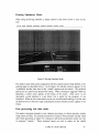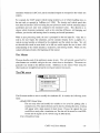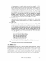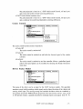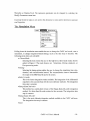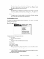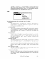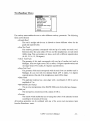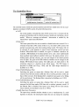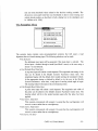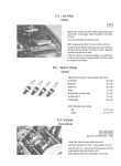
1
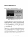
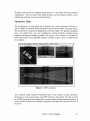
.ation Too for a Roaddeparture Avoidance System
User's Manual
CAPC v4.2
February 1997
'The University of Michigan
Paul J.Th. Venhovens
Transportation Research Institute
David J. LeBlanc
Dept. of Mechanical Engineering Br Applied Mechanics
~ l a@
r ,t
% .rlVP .$
@
; ;,
The University of Michigan z ,,I,
Transportation Research Institute
Technical Report Documentation Page
1. Report No.
3. Recipient'r Catalog No.
2. Government Accession No.
UMTRI-97-13
8. Performing Organization Report No.
7. Author(8)
P. Venhovens, D. LeBlanc
10. Work Unit No. (TRAIS)
0. yerform!ng Or ani?atio? Name and Addrew
Un~vers~tv
o! Mlchlaan Trans~ortationResearch Inst.
and ~ e pofi ~ e c h i n i c a~l n gand
r Applied Mechanics
Universitv of Michiaan
, 48159-2150
Ann ~ r b d rMI
13. ~ y p e
of Report and Period Covere~d
12. Sponroring Agency Name and Addrean
I
14. Sponroring Agency Code
I
16. Supplementary Notea
This document is an introductory user's manual for the Crewman's Associate for Path
2ontrol (CAPC) simulation tool, version 4.2. This user's manual replaces all manuals
lor previous versions.
SAPC v4.2 is a Macintosh-based software package for simulating a road-departureprevention system. A menu-driven user interface allows the user to define dynamics
models for the vehicle (including tires, suspension, disturbance effects, roadw~iy
effects), the roadway geometry, and the road-departure-prevention system, which
:an contain a warning and/or ari active intervention mode. CAPC v4.2 can be run in
three modes: numerical simulation, desktop driving simulator, and post processing for
zomparing actual vehicle data vvith simulation. Version 4.2 is available for both the
PowerPC generation of Macintoshes and the previous 68K Macintoshes with FPU.
1
17. Key Word6
automotive safety, simulation,
driving simulator, road departure,
vehicle dynamics
18. Dirtribution Statement
This document is available to the public through:
National Technical Information Service
5285 Port Royal Road
Springfield, VA 22161
I
1% Security Claraif. (of thin report)
Unclassified
20. Security Ciareif. (of thir page)
Uncl'assified
21. No. of Pager
30
22. Price
Table of Contents
About this Manual .................................................................................
2
For more information ..............................................................................
3
Descriptionof theCAPCv4.2Tool .............................................................
4
4
Introduction ................ ...........................................................
DynamicsModels.........................................................................5
How to Use the Simulation Tool .................................................................7
TheThreeModes .........................................................................
7
Simulation Mode .................................................................8
Driving Simulator Mode ........................................................9
Post processing test data mode .................................................9
TheMenus .................................................................................
I0
The File menu ....................................................................10
TheModelsmenu ................................................................11
The Simulation Menu ........................................................
18
The Disturbance Menu ..........................................................19
The Roadway Menu .............................................................21
The Controllers Menu ...........................................................22
The Scenarios Menu .............................................................23
The Window Menu ..............................................................24
References .........................................................................................-24
.
.
i-
About this Manual
This user manual introduces the use of the CAPC (Crewman's Associate for Path Control)
simulation tool, v4.2. This software is for the design and evaluation of road-dep;~rtureprevention systems, and was used to design and eventually implement the CAPC roaddeparture-prevention system on a vehicle at the University of Michigan. The software
features a comprehensive set of user-friendly pull down menus to allow selection and
revision of countless dynamics model modules, sensor systems, and warning and control
parameters. This guide introduces the basic capabilities and elements of using the system.
Other references are provided a.t this report's end for more detailed information about the
dynamic models and the control and logic modules, as well as the CAPC road-departure
work.
Files needed: To begin using the software, you must have the CAPC v4.2 application
(program), and seven data files, which should be packaged with the CAPC, and a
Macintosh computer. There are two versions of the CAPC v4.2: one for older "68K"
Macintoshes (pre-PowerPC), named CAPC v4.2 (68K), and one for the PocverPC
Macintoshes, named CAPC v4.2 (PPC). The seven data files include an input file (named
Default.STP) containing default parameters a ~ six
d files each containing tables that descrjbe
a different road surface unevenness. These files are called: Faulted PCC, Good PCC, and
SO on.
For any numerical design or analysis needs, you will want to know about the output file
format that CAPC v4.2 produces (called ERD). The CAPC tool saves the user's choice of
variables during the course of the simulation. This data can be directly plotted using a
plotting package named EP, or the file headers can be easily stripped off and the data
imported into any plotting package or spreadsheet. EP is either enclosed with the other
files, or is available on the Web site at the University of Michigan Transportation Research
Institute (UMTRI):
http://www.umtri. umich.edu/erd-soft/ep. html/ .
System reauirements: Apple Macintosh (68K processor with FPU, or PPC), about 5MB
RAM, and 5 MI3 hard disk space. Color monitor, 15" or larger, recommended, but any
will do. Does not work on most pre-1996 PowerBook laptops (100, 200, 500 series),
except those with an FPU.
PC or UNIX version status: Contact Professor Huei Peng at the University of Michigan if
you must have an IBM-compatible or a UNM-compatible version. He's developed a
version for the graphics library OpenGL. This is available, albeit with fewer capabilities
than that of the Macintosh version, and is aimed at intelligent-cruise-control uses.
CAPC v4.2 User's Manual
More information on the s o f t \ w A Reference Manual was written by P. J.Th.
Venhovens in 1995. This 100-page document describes in detail the dynamics models.
See the contacts below to obtain1 this.
For more information
Contacts:
Director of the CAPC projects:
Mr. Robert E. Ervin, Head, Engineering Research Division, The University of
Michigan Transportation Research Institute (UMTRI), 2901 Baxter Rd., Ann
Arbor, MI 48109-2125, USA. Phone (3 13) 936-1066. Email
[email protected].
Resident software developer:
Mr. Kevin O'Malley, UMTRI. Email ornalley @umich.cdu.
Manuals and papers:
See the Web site:
http://www-personal.engin,umich.edd-leblanddir. researcWActiveSafety.lztml
or contact Professor A. Galip Ulsoy at the University of Michigan.
CAPC v4.2 User's Manual
Description of the CAPC v4.2 Tool
Introduction
The different subsystems of a lane-departure-avoidance system have been combined on a
simulation level in the CAPC (Crewman's Associate for Path Control) simulation tool. The
simulation tool is a modular concept written in C-language and runs on Macintosh
computers using either a PowerPC (PPC) or an older Motorola 680x0 (68K) processor.
The main objective of the tool is to integrate subsystems into one lane-departure-avoidance
system and to study the performance and interaction among the different modules, as well
as to evaluate the overall system behavior and performance. The seven major parts of the
CAPC simulation tool are the vehicle, the lane marker recording and processing, the
estimation of the future trajectory of the vehicle, the time-to-lane crossing calculation, the
brake-steer controller, the driver status assessment and the CAPC supervisory controller.
-
The tool has three modes: (1) siniulation mode, (2) desktop driving sirnulator mode, and
(3) combining actual road test data with simulations. The modes have different uses, but
all use the same models for dy~~amics,
control, and sensing, and all three modes l1zT~ea
sinilar look and feel.
The tool was used for design, evaluation, and preliminary testing of the CAPC systern. An
example of the use of the tool was an investigation into the influence of external
disturbances road unevenness and wind - on the estimatior, of roadway geometry. A
vision system is mounted rigidly onto the body (sprung mass) of the vehicle, so estimates
of the lane edge locations are affected by unknown roll and pitch motions of the sprung
mass. The simulation tool led us to add pitch and roll sensors, but to realize that only the
lower frequency motions need be known, simplifying both hardware and software.
-
.
-
An example of a system design problem was a study to evaluate whether the roadway
geometry estimation algorithm would work on a steeply banked test track that was available
for our early vehicle testing. This required a simulation tool with the combination of
roadway and vehicle modeling, vision sensor and estimation modeling, as well as the
ability to compute the metrics ar~dlogic used to initiate warnings to the driver. The finding
was that while Kalman filters meliorate the problem of large superelevation, there is a
tradeoff between obtaining good performance in the turn, versus good performance
approaching the turn - essentially, the weighting of vision data against vehicle motion data.
The simulation tool has played a significant role as the CAPC system grew to its final
(hardware) design. Before testing on the road or proving grounds, control strategies have
CAPC v4.2 User's Manual
-4-
been irnplemented in the simulation tool to verify their efficiency and stability. The ability
to exchange code has simplified and shortened the implementation phase significantly.
Dyna.mics Models
The core of the simulation is the vehicle models. While driving on the road the vehicle is
subjected to many external inputs, such as driver steering wheel actions, road unevenness,
and wind. The CAPC simulation tools offers a variety of vehicle models, each deisigned
for a specific application. The most extensive model contains 14 degrees of freedom
(DOF). The sprung mass is able to move in three directions (longitudinal, lateral and
vertical) and to rotate about three axes (roll, pitch and yaw). Each wheel suspension has
one DOF with respect to the vehicle body and the rotation of a wheel also accounts for one
DOF. Simpler models are available via pull-down menus, as described later.
The tire accomplishes three basic functions: (1) supports the vehicle weight, cushioning
road irregularities, (2) develops lateral forces for cornering, and (3) develops longitudinal
forces for accelerating and braking. Several tire models are available in the CAPC
simulation tool. The most extensive model is based on an empirical model known as the
Magic Formula model. It describes tire slip forces for a large range of load and slip
quantities. It also can handle cases of combined slip (cornering and braking or accelerating
). The less extensive models are based on the Magic Formula, but contain simplifications to
speed computations.
The CAPC simulation vehicle can be operated on various roadway types with different
geometries and unevenness. Besides an oval test track, a straight road, a winding roa~d,and
a skid pad have been preprogrammed. The geometry can be extended with grades and
superelevations. Furthermore, several data sets of different, artificially-generated road
unevenness profiles are available. The road friction coefficient can be changed, too.
Two driver models are available in the CAPC simulation tool. The simple driver mlodel is
characterized by a preview model that looks at a single point in front of the vehicle. The
other option is a more elaborate optimal preview model that minimizes the tracking error at
several points in front of the vehicle.
The CAPC vehicle was designed to use two vision cameras: one for the near-field range
and one for the far-field range. In the CAPC simulation tool, the images of the cameras are
determined by applying several coordinate transformations to the known roadway geometry
in front of the vehicle, assuming a flat earth model. The hardware specifications (camera
CCD chip size and resolution) have been modeled. Furthermore, the position of the
cameras on the vehicle, the orientation, and the update frequency can be chosen arbitrarily.
The following subsystems are available in the CAPC simulation tool:
+ Vehicle Models
CAPC v4.2 User's Manual
7 DOF flat vehicle model: longitudinal, lateral, yaw and 4-wheel rotational DOF
8 DOF yawlroll model: 7 DOF model + roll DOF
14 DOF full vehicle model: 6 DOFs for the vehicle body, 1 DOF for each axle and
4-whe,el rotational DlOFs.
+ Tire Models
Steady-state (different road friction coefficients possible):
* Cornering stiffness as a function of vertical tire load
* Magic Formula (pure slip, combined slip)
Transient: first-order relaxation system (tire load dependent).
+ Anti-Lock Brake System Model
First-order lag system with brake pressure saturation.
+ Driver Model
a Simple preview model with driver limitations (time lag).
U M T H s optimal preview driver model.
+ Cruise-Control (set, resume, accelerate)
+ Far-Field Camera determining the future roadway geometry.
+ Near-Field Camera determining the heading angle and lateral deviation.
+ Path Prediction based on
2 DOF linear flat vehicle model (lateral and yaw DOF).
* Linear tires, fixed cornering stiffness
* Nonlinear tires, cornering stiffness as a function of vertical tire load
3 DOF linear yawlroll vehicle model (lateral, roll and yaw DOF).
* Linear tired, fixed cornering stiffness
* Nonlinear tires, cornering stiffness as a function of vertical tire load
+ Lane Margin Calculation time-to-lane crossing.
+ Driver Status assessment based on vehicle states and steering wheel activation.
+ Brake-Steer Controller based on LQ feedback of the lateral deviation, heading
angle, side slip velocity and yaw rate.
+ CAPC Supervisory Controller based on driver status and time-to-lane crossing.
+ Roll and Pitch angle estimation based on measured suspension deflectio~is.
+ Road Unevenness collected from empirical road models.
+ Roadway Geometry straight lines, curves w Iw/o superelevations and/or sl~opes.
+ Wind Disturbances constant wind, crosswind gust, random crosswind.
+ Real-Time Driving Simulator
8 DOF yawlroll model including wheelspin DOF, Magic Formula tires, cruise
control, path prediction, lane-margin calculation, warnings and interventio~i.
CAPC v4.2 User's Manual
How to Use the Simulation Tool
The Three Modes
When starting up the CAPC simulation tool the following screen will appear:
Figure 2. CAPC start-up screen (for an earlier version).
The simulation tool offers three modes of operation. The first mode is the Simululion mode
which includes all the features of the lane-departure-avoidance system. The second mode is
a real-time driving simulator mode a scaled-.down version of the ordinary ,simulutiolz
mode. Some items have been disabled (such as the 14 DOF vehicle model) because of the
computational burden. The driving simulator mode offers an animated view of the vehicle
and roadway as seen through the eyes of the driver. The third mode is a post processor
option that allows the user to input measured steering wheel angle and vehicle speed from
the prototype car directly into the simulation. The input file needs to be an ERD binary file
with specific channel short names.
-
The three modes can support different objectives. For example, the simulation 1n1ode is
useful for the designer who needs to perform experiments with well known driver inputs to
develop or evaluate the road-departure system or a subsystem. The driving simulator
mode, which is usually operated using the mouse as a steering wheel, is useful to both
demonstrate the system (or subsystem), but also to test behavior when driver steering
inputs are closer to real. For instance, an error in our first warning logic was uncovered
with this mode the error appeared only when the center line had been crossed twice.
"Driving" for five minutes allows the engineer to quickly test many scenarios.
-
CAPC v4.2 User's Manual
The third mode is useful for comparing data measured in a real vehicle with the simiulation
computations. This was used to tune vehicle dynamics and tire dynamics models, and to
calibrate the model for our steering system dynamics.
Simulation Mode
The simulation tool is menu driven and is supported by various animations. The user is
able to modify all important model parameters using pull-down menus and dialog boxes.
The simulations are supported by graphical and numerical outputs. The graphical animation
shows the vehicle from a top view including the roadway geometry, predicted future
trajectory and perceived roadway geometry. The scenery of the roadway as recorded by
both vision systems is also displayed during the animation. Figure 1 gives an i~npressionof
the animation.
Figure 1. CAPC simulation.
The numerical output contains all important states of the vehicle, roadway geometry,
disturbances, vision system outputs, and CAPC control in- and outputs. The data is stored
in an ERD format and can be displayed by a separate, public-domain engineering plotter. It
is also possible to look at the silnulation in progress (real-time) from the point of view of
the driver.
CAPC v4.2 User's Manual
Driving Simulator Morde
When using the driving simulator, a display similar to that shown below is seen by the
user:
&
File Model Simulation Disturbances Roadwau Controllers Scenarios Window
Figme 2: Driving Simulator Mode
This mode is most often used in conjunction with the computer mouse being defined as the
steering input (as described below). In the figure, the selected roadway appears in the
"windshield" and the white hood of the "vehicle" appears near the bottom. The predicted
path is seen as a yellow trace ahead of the vehicle. When a warning is triggered within the
algorithm, a yellow arrow appears at the bottom of the screen. (This arrow is not
necessarily a good interface to a real driver, but is useful for the purposes of our
simulator.) When an active intervention occurs (we use differential braking), a red bar near
the bottom moves to the left or right, indicating the amount of brake pressure applied ,to the
brakes.
Post processing test data mode
This mode is designed primarily for the validation and tuning of vehicle dynamics m.odels
using vehicle test data. An external test data file is required, which includes steering wheel
and vehicle speed data as "inputs" for a maneuver, and lateral accelerations and/or yaw rate
as measured "outputs." These measured inputs are used as inputs for the vehicle
CAPC v4.2 User's Manual
-9-
simulation within the CAPC tool, and the simulated outputs are conipared to the vehicle test
outputs.
For example, the CAPC project vehicle testing included a set of vehicle handling tests on
the test track, as reported in L~Blancet al. 19961. The steering and vehicle speed data
were then fed into the CAPC tool using the post processor mode, and the measured lateral
acceleration and yaw rates were compared to the simulated values. This allowed us to
choose vehicle dynamics parameters, such as tire cornering stiffnesses, roll damping and
stiffness, yaw inertia, and steering wheel-to-steering rack model parameters.
While in post processing mode, the user is prompted for the test iriput file. Once this is
read in, the user begins the simulation, and the computer display shows a graphic of a
vehicle moving laterally as indicated by the simulation and the vehicle test data. We will
not describe this mode in more detail, as its full use would require the user to have: a fill1
understanding of the vehicle dynamics, suspension, and steering models. Please use the
contact information listed at the beginning of this manual.
The Menus
We now describe each of the pull-clown menus in turn. This will provide a good feel for
what features are available, and give the user a basic how-to description. The menus are
generally very similar in the different modes. Differences in the menus when using the
other modes are straightforwarcl and do not require separate discusl;;ion.
The File menu
'
Model S i m u l a t i ~ n
I
Modify ERD Output Setup
... )
...
Saue Simulation Setup
Load Simulation Setu pi...
Load E R I l test file
Quit
...
--
The file menu enables to user to modify the simulation 10. It contains the following menu
items:
Modify ERD Output Setup
The user may select and modify the variables to be saved for plotting after a
simulation run. The output selection can be done by selecting this item. A dialog
will appear with a large amount of check boxes. Choose the signals that you
would like to study after a simulation run. The data will be stored in a text ERDformat and the signals can be viewed using the ERD plotter.
Save Simulation Setup
CAPC v4.2 User's Manual
All the parameters of a specific vehicle are stored in a setup file (*.STP).
Besides vehicle parameters the setup file contains simulation-related parameters,
such as time-step, road unevenness and controller gains. After modifying the
vehicle and simulation related parameters, the setup can be saved by selecting
this menu item. The setup file needs to have the extension .STP. When starting
up the simulation tool the default vehicle parameters will be loaded from ithe file
DefaultSTP. Po not erase this file or hundreds of d,efault
parameter values will be lost! This default file contains information
which approximates a 1995 Ford Taurus SHO, the vehicle used to implement
the CAPC road-departure-prevention system [LeBlanc et al. 19961.
Idad Simulation Setup
A previously saved setup can be loaded by selecting this item. All the current
vehicle and simulation related parameters will be replaced by the data from the
setup file.
Load ERD test file
This option is only selectable in the Post processor mode of the CAPC
simulation tool. A file in an ERD format with specific short names will be used
to run a simulation in a post processor mode. This file must be recorded with
the CAPC prototype vehicle and MacDAS software. The front wheel steer angle
and vehicle speed as stored in the ERD file are ported directly into the
simulation tool such that a simulation can be carried out with measured driver
inputs. The ERD file must be in a binary floating-point format and needs to
contain the following short names:
- d-sw (steering wheel angle in degrees)
- d-fw (front wheel steer angle in degrees)
- u-RF (right front wheel speed in mls)
- u-LF (left front wheel speed in m/s)
- u-RR (right rear wheel speed in m/s)
- u-LR (left rear wheel speed in mls)
The vehicle speed is derived by averaging all four wheelspin-derived speeds.
Quit
Selecting this menu item will quit the simulation program.
The Models menu
The models menu allows the user to select and modify items related to the dynamics
models. Different models for the vehicle, tires, driver and path prediction can be selected.
The complexity of the model varies with the selection and it is also possible to change
specific parameters of each model. The models menu contains eight items: vision system,
vehicle models, tire models, antilock brake system models, driver models, path prediction
models, cruise control model, and driver status model. Each of these is now described.
CAPC v4.2 User's Manual
Vision System
Rnti Rock Brake System
...
...
Path Prediction
Cruise Control...
The CAPC vehicle is equipped with two vision systems (digital video cameras):
Near-Field Camera
The near-field vision system is scanning the roadway geometry close in front of
the vehicle.
0 Far-Field Camera
The far-field vision system is also scanning the roadway geometry in front of
the vehicle. However, the range is longer than that of the near-field camera.
Both vision system-related menus come with a submenu. The cameras are fixed on the
vehicle body. This implies that the images of the cameras are affected by the vehicle
motions. These motions include body roll during cornering, pitch during braking or
acceleration, or a combination of heave, roll and pitch resulting from operation on an
uneven road. The transformation from screen coordinates to roadway x-y coordinates can
be adjusted if the motion of the vehicle is known. Two options are available:
No Compensation
No compensation means that the motion of the vehicle is not included in the
transformations from image coordinates to roadway geometry coordinates.
Roll & Pitch Compensation
A correction will be applied in the transformation based on estimates of tlhe roll
and pitch angle of the vehicle determined by suspension defllection
measurements.
The last submenu item is:
Modify Parameters
Selecting this menu item enables the user to modify the position and orientation
of the cameras on the vehicle. Furthermore, the focal length, image update rate
and the range of interest can be changed.
CAPC v4.2 User's Manual
Vehicle Model
,
~ i l e ~ S i m u l a t i oDisturbances
n
Roadway Controllers
Scenarios Window
I
flnti Lock Brake System
Driver...
Path Prediction...
Cruise Control...
Driver Status
...
...
7
2 D@FFlat Llehicle Modet
7 DOF Flat Uehicle Model
b B DOF Yaw-Roll Uehicle Model
b 4 14 OOF Full Uehicle Model
b
#
b Modify Uehicle Parameters...
b
Modify Suspension Characteristics
... I
The vehicle model menu enables the user to change the type and complexity of the vehicle
model and to alter the parameters of this model. It contains the following seiections:
2 DOF Flat-Vehicle Model
The 2 DOF vehicle model is characterized by the lateral and yaw DOFs. This
model can only be used in the Post processor mode,
7 D 3 F Flat-Vehicle Model
The 7 DOF vehicle rriodel is characterized by the following seven degrees of
freedcnl: longitudinal, lateral, yaw, and four wheel rotational DOFs.
o 8 DOF Yaw-Roll Vehicle Model'
The 8 DOF vehicle model is characterized by the following eight degrscs of
freedom: l,ongitudinal, lateral: roll, yaw and four wheel rotational DOFs.
14 DOF Full Vehicle hiodeel
The 14 DOF vehicle model is characterized by thz 6 DOFs for the vehicle body,
1 DOF for each axle and four wheel rotational DOFs.
Modij) Vehicle Pnmmctem
This menu itttn enables the user to change important vehicle parameters sac11 as
the masses: moments of inertia, and vehicle speed of travel.
ModEfy Suspension Chart~cteristics
The suspension spring and damping constants can be changed if t h ~ siterri is
selected. Furthermore it allows the user to change the vertical tire stiffness and
auxiliasy roll stiffness of the anti-roll bars.
Modify Suspensiori Geometry
The geometry of the front and rear suspensions can be altered by selecting t h ~ s
item. The geometry of the true suspension has been represented by a simplified
suspension model. Modifying the parameters will affect the track width arid roll
center height.
ModiJ) Aerodynamic Parameters
The six aerodynamic coefficients of the vehicle body can be changed whe:n this
item is selected. Furthermore, the frontal area of the car. the barometric pressure
and air temperature can be altered.
CAPC v4.2 User's Manual
Tire Model
...
...
Path Prediction
Cruise Control
dMagic Formula Tire Model (pure slip)
The tires are separated from the vehicle menu item. The following slip force models can be
chosen:
* Cornering StifSness (constant)
This tire model is the simplest model available. It is using constant slip
stiffnesses to calculate the tire slip forces and moments.
* Cornering StifSness (load dependent)
This tire model takes the load dependency of the slip stiffnesses into alccount
while calculating the tire slip forces.
* Table Look-up Based on Magic Formula
The Magic Formula is an empirical tire model that is valid for a wide range of
load/slip combinations. The output of the model is a longitudinal and lateral tire
slip force, and the aligning moment. The inputs are the longitudinal slip, the
sideslip angle, the vertical tire load and the wheel camber angle. The table lookup version of the Magic Formula is based on a table that is filled with numbers
generated by the original version of the Magic Formula. This version is faster
because less computations have to be carried out. The table look-up version
doesn't consider combined slip (cornering and braking at the same time).
Magic Formula Tire Model (pure slip)
This tire model is identical to the look-up version as described above. It uses the
original Magic Formulae and considers only pure slip situations.
Magic Formula Tire Model (combined slip)
The combined slip version of the Magic Formula is the most extensive tire
model available in this simulation tool. Unfortunately, the computational burden
is significant.
Transient Tire Model
Selecting this menu item toggles the transient tire model on or off. The transient
tire model is based on a first-order relaxation system with a load dependent
relaxation length. This option can be combined with any of the five previously
described steady-state tire models.
ModiJ) Parameters
Selecting this item will allow the user to modify the tire-road friction coefficient.
CAPC v4.2 User's Manual
- 14-
Anti-Lock Brake System Model
Simulation
Lane Sensors
Uehicle,..
Tires
...
...
Disturbances Roadway Controllers
,I
b
Modify Parameters...
Path Prediction
Cruise Control
Driuer Status.
I
...
...
..
Some of the dynamic properties and parameters of the anti-lock brake system can be altered
by selecting:
Modzfi Parameters
Several brake system related parameters can be changed, such as effective rotor
radius, brake cylinder bore, friction coefficient between pad and rotor, and the
time constant of a first-order system used to model the brake system dynamics.
Driver Model
The CAPC simulation tool has two different kinds of driver models built in:
Simple Preview Model
This model is relatively simple and steers the vehicle by tracking one point at a
fixed distance in front of the vehicle. The model includes characteristics of the
human driver, such as neuromuscular related dynamics and time delay. The
simplicity of the model restricts the application to straight line driving.
Optimal Preview Model
This model is a more sophisticated version of the simple preview model. It
minimizes the tracking error at several points in front of the vehicle. This model
is better for complicated maneuvers and driving through curves. The model also
includes a pure time delay.
Besides the two driver models the following options are available:
Mouse Driving
The vehicle can be steered by moving the computer mouse from left to right.
The neutral position corresponds to the middle of the screen.
No Driver, Fixed Steering Wheel
CAPC v4.2 User's Manual
As the name already suggest, the steering wheel is fixed in the neutral position
with this option.
The characteristic parameters of the driver model can be altered by selecting:
Mod& Parameters
Depending on the driver model chosen (simple, optimal preview, mouse driver)
the selection will enable the user to modify time constants and gains.
Path Prediction Model
ck Brake System
...
Uehicle Model (linear tires)
2 DOF Flat Uehicle Model (non-linear tires)
I
I
The time-to-lane crossing algorithm as used in the CAPC program uses the future vehicle
trajectory as an input to the calculations. The future path of the vehicle is based on a simple
vehicle model assuming that the steering wheel position and vehicle speed remain constant
during the projection. The path is obtained by integrating the differential equations of the
vehicle. Appropriate initial conditions are necessary. The following path prediction
modelslmethods are available:
Steady-state Curve
The steady-state curve prediction is based on the steady-state solution of the
differential equations of a 2 DOF vehicle model (lateral and yaw). The solution
has the shape of a curve with a fixed radius. The radius depends on the steering
wheel input, vehicle parameters and speed of travel.
2 DOF Vehicle Model (linear tires)
The path projection is based on a 2 DOF vehicle model (lateral and yaw) and a
linear tire model (constant cornering stiffnesses).
2 DOF Vehicle Model (nonlinear tires)
The path projection is based on a 2 DOF vehicle model (lateral and yaw) and a
nonlinear tire model (load dependent cornering stiffnesses).
2 DOF Vehicle Model (linearized)
The path projection is based on a 2 DOF vehicle model (lateral and yaw) and a
linear tire model (constant cornering stiffnesses). The geometry related to the
path prediction has been linearized: cos(g) = 1, sin(y) = g .
3 DOF Vehicle Model (linear tires)
CAPC v4.2 User's Manual
The path projection is based on a 3 DOF vehicle model (lateral, roll and yaw)
and a linear tire model (constant cornering stiffnesses).
3 DOF Vehicle Model (nonlinear tires)
The path projection is based on a 3 DOF vehicle model (lateral, roll and yaw)
and a nonlinear tire model (load dependent cornering stiffnesses).
Cruise Control
Lock Brake System
...
The cruise control has three modes of operation:
o Cruise Off
The cruise control is switched off.
Cruise On
The cruise control is switched on and holds the forward speed of the vehicle
constant.
0 Accelerate
The cruise control is switched on and the controller follows a predefined speed
pattern. The speed pattern can be modified by selecting the Modify Parameters
menu item.
Driver Status Model
Path Prerliction
...
The status of the driver can be an input for the CAPC decision module. The algorithm
monitors several vehicle-roadway related signals such as lateral deviation of the vehiclle and
steering wheel input. The moving average and standard deviation values are combined to
one quantity denoted by PERCLOS (the proportion of the time that the driver's eyes are 80
to 100 percent closed), a quantity described in technical reports and papers from MT. W.
CAPC v4.2 User's Manual
Wienville at Virginia Tech. The regression parameters can be changed by selecting the
Modify Parameters menu item.
Currently the driver status is not used in the decisions to warn andlor intervene to prevent
road departure.
The Simulation Menu
Simulation Timing ...
Euler 1 st-order
Pulling down the simulation menu enables the user to change the CAPC tool mode, start a
simulation, or change integration-related settings, such as the time step or duration,. The
following menu items are selectable:
Choose Mode
Selecting this item returns the user to the high-level, three-mode choice shown
earlier in Figure 2. The mode choices are: Simulation, Driving simulator, or
Post processing mode.
Timing
Selecting the timing option enables the user to change the simulation time step,
duration, and communication interval. The communication interval detenmines
the output to the ERD-data file and to the screen.
0 Euler 1st-order
This is the fastest integration routine available. The integration of the differential
equations is less accurate than with the more elaborate methods. The integration
time step is constant.
Runge-Kutta 2nd-order
This method is a scaled-down version of the Runge-Kutta 4th-order integration
method. It is faster than 4th-order routine but less accurate. The integration time
step is constant.
Runge-Kutta 4th-order
This is the most elaborate integration method available in the CAPC software.
The integration time step is constant.
Start
CAPC v4.2 User's Manual
Selecting this item will start the simulation. A dialogue box appears, allowing
the user to assign a name to the ERD output file. The simulation can be
interrupted by pressing a button on the mouse.
Continue
After termination of a simulation run (by pressing a mouse button) it is possible
to continue with the simulation from the current position. The initial values
correspond with the values after the termination of the previous simulation run.
Reset
This option resets all the state variables in the simulation. All initial con~ditions
will be set to zero (with exception of the vehicle speed).
The Disturbance Menu
The vehicle can be subjected to different kinds of disturbances. Two sources are available:
road unevenness and wind.
Road Irregularities
Wauy Surface Tre
This menu offers the following selectable items:
No Unevenness
The road surface is smooth.
Good PCC
where PCC stands for Portland Cement Concrete.
Faulted PCC
Rough Asphalt
Wavy Sumce Treatment
Test track north straight
This is a road unevenness data file derived from a measured data file recorded at
a nearby test track, on the north straightaway.
Test track -south straight
This is a road unevenness data file derived from a measured data file recorded at
a nearby test track, on the south straightaway.
Artificially Generated Slabs
-
CAPC v4.2 User's Manual
The length of the slabs is 9 in. They are modeled as smooth flat plates with a
slight positive slope. The joints between the plates is discontinuous and the
discontinuity is modeled as a random process. The height difference during the
transition from plate to plate ranges between 6.4 and 12.7 rnm.
Wind
Continuous Wind
Crosswind Gust
Random Crosswind
DC + Random Crosswind
11
I
I
Modify Wind Parameters...
The wind disturbance menu offers the following items to be selected:
* No Wind
The vehicle will not be exposed to wind disturbances. There will be no
aerodynamic forces acting on the vehicle. Even the speed of the vehicle itself
does not generate aerodynamic forces.
Continuous Wind
There will be a continuous wind speed present. The direction and the magnitude
of the wind speed can be altered in the Modify Wind Parameters menu item.
The orientation of the wind is assigned in an inertial frame. The default wind
speed is zero.
* Crosswind Gust
The gust is a side wind speed with an orientation according to the y-axis of the
inertial coordinate system. The gust is of a pulse shape. The start time, stop
time and DC wind speed can be altered by selecting the Modify Wind
Parameters menu item,
Random Crosswind
The random crosswind gust is identical to the Crosswind Gust as explained
above except that the wind speed is randomly distributed. The random speed
effect has been obtained by low-pass filtering of white noise. In addition to the
start and stop time, the standard deviation and frequency contents of the random
component can be changed by selecting the Modify Wind Parameters menu
item.
DC t Random Crosswind
This option is identical to the Random Crosswind except that the random. wind
speed is superimposed on a DC side wind speed,
Modify Wind Parameters
Depending on the type of wind disturbances chosen, selecting this item will
allow the user to modify particular wind parameters such as speed and pulse
duration times.
CAPC v4.2 User's Manual
- 20 -
The Roadway Menu
Controllers Scenarios
Straight Road
b
Oval Test Track
b
Tacom Test Track
Dana Test Track
Sinus Road
IS0 Double Lane Change
Skidpad
------.----------*
Season
b
The roadway menu enables the user to select different roadway geometries. The folllowing
items can be selected:
Straight Road
The road is straight and the user is allowed to choose different values for the
grade and superelevation.
Oval Test Track
This roadway geometry corresponds with one lap of a nearby test track: oval.
Both turns have the same radius (381 m) and the straightaways are each about
1600 m long. This oval contains six lanes, each with a different superelevation
(0, 0.5, 2.5, 6, 15, 28 degrees).
Short Test Track
The geometry of this track corresponds with one lap of another test track in
Michigan. It has two tight curves (102 m radius, 0 degrees superelevatioin) and
one larger bend (145 m radius, 8.5 degrees superelevation).
Steep Test Track
The geometry of this track corresponds with the track from yet another track in
Michigan. It is an oval with two identical bends (279 m radius, 6.2 degrees
superelevation) at the end of the straightaways (each 408 m long).
* Sinus Road
This particular roadway has a sine-shape with a wavelength of 200 m and an
amplitude of 2 m.
IS0 Double Lane Change
This is a free interpretation of the ISOITR 3888 norm for double lane changes.
Skid pad
The skid pad is a circular track with a radius of 100 m.
Seasons
The season switch enables the user to change the colors of the animated screens
according to the seasons of the year.
All roadway geometries can be combined with any of the seven road unevenness types
from the Disturbance menu.
CAPC v4.2 User's Manual
The Controllers Menu
/Far-Field LM Kalman Filter
I
I
Modify Superuisor Parameters...
LOR State Feedback
I
Modify PID Feedback Gains
II
The controller menu controls the specific hardware and software related items for the roaddeparture-avoidance (CAPC) system. It has the following items:
CAPC
The switch enables or disables the entire CAPC system. If it is switched off the
program will simulate only the vehicle dynamics related part (including a driver
model). When on, warnings are indicated. Intervention is enabled by the
"Brake-Steer" option described below.
Brake-Steer
This menu option allows the user to enable or disable brake-steer control. If it is
switched off and the CAPC system switch is on, the entire CAPC system will
operate in an open-loop, with only warnings being issued. The brakes will not
be activated if a road departure is sensed when brake-steer control has been
disabled. When Brake-Steer is enabled, two types of feedback controllers are
available: a PID feedback of the lateral position error, and a more sophisticated
linear quadratic state feedback controller which uses the lateral position error,
heading angle, side-slip velocity, yaw rate and integral of the lateral position
error as inputs. The gains of the PID feedback controller can be changed in the
Modijj PID Feedback Gains option. The LQR gains are hard-coded in the
simulation software as a function of the vehicle speed. The PID design is
described in [Pilutti and Ulsoy, 19951, and the LQR design described in
[LeBlanc et al. 19951.
0 Near-Field LM Kalman Filter
Switching this option on means that a Kalman filter will be used to match
measured near-field Pane marker (LM) data with a roadway geometry model and
thus to filter out noise. If the Kalman filter is disabled, least square curve fitting
will be used instead. The Kalman filter is described in [LeBlanc et al. 19951.
Far-Field LM Kalman Filter
Switching this option on means that a Kalman filter will be used to match
measured far-field lane marker (LM) data with a roadway geometry model. If
the Kalman filter is disabled, least square curve fitting will be used instead.
These methods are described in [Lin et al. 1995bl.
Modijj Supervisor Parameters
The supervisory controller decides whether or not to wadintervene if a road
departure is detected. By selecting this option the user can change the sampling
CAPC v4.2 User's Manual
rate and some threshold values related to the decision making module. The
decision to warn andlor intervene uses thresholds on time to lane-crossing and
vehicle lateral position, as described in both a dialog box in the simulatilon and
in L,eBlanc et al. 19961.
The Scenarios Menu
Controllers
Window
J N o Scenario
Tue
--
( l a ) Straight Road, Step Steer
( I b ) Straight Road, Pulse Steer
(2a) Curue, Step Steer
(2b) Curve, Pulse Steer
(3) Curve, No Steer
Modify Scenario Parameters
...
The scenario menu contains some pre-programmed scenarios that will cause a. road
departure due to a forced steering input. The following selections can be made:
No Scenario
No additional steer input will be generated if this menu item is selected. The
driver input whether through a model (see Model menu) or the user using a
mouse is used directly.
* ( 1a ) Straight Road, Step Steer
A step steer input will initiate a road departure. The magnitude and timing of the
step can be altered in the Modify Scenario Parameters menu item. The
simulation begins with the default driver model steering the simulated vehicle.
At the appropriate timing, as defined by default or by the user in the Modify
Scenario Parameters menu item, a step input of steering wheel angle is input.
The steering wheel will remain in the non-neutral position.
(1b) Straight Road, Pulse Steer
A pulse steer input will initiate a road departure. The magnitude and width of
the pulse can be altered in the Modify Scenario Parameters menu item. The
steering wheel will be in the neutral position again after the pulse has been
applied.
(2a) Curve, Step Steer
This scenario corresponds with scenario la except that the road departure will
occur in a curve rather than on a straightaway.
(2b) Curve, Pulse Steer
This scenario corresponds with scenario 1b except that the road departure will
occur in a curve rather than on a straightaway.
* (3) Curve, No Steer
-
-
CAPC v4.2 User's Manual
The steering wheel is fixed in the neutral position and the vehicle is apprclaching
a curve.
Modify Scenario Parameters
Selecting this item enables the user to change the timing and magnitude of the
forced steering wheel input.
Selecting one of the scenarios will not only initiate a road departure, but also other menu
options such as roadway and tire model will be altered depending on the scenario chosen.
With all scenarios, the driver model will be disabled once a steplpulse steer is initiated.
The Window Menu
JUehicle I
/Uehicle I I
/Near-Field
/ Far-Field
Screen
Screen
With the window menu the user is able to enable or disable the animated screen output of
the simulation tool.
Vehicle I
This window corresponds with the large rectangular window on the bottom of
the screen and shows the vehicle, roadway, and camera ranges.
Vehicle 11
This window shows a close-up of the vehicle only, The red lines on every
corner of the vehicle represent the magnitude of the tire slip forces
Near-Field Screen
This screen corresponds with the image as seen through the near-field camera.
Far-Field Screen
This screen corresponds with the image as seen through the far-field camera.
The Vehicle 1/11 windows and the two camera images are updated with different
frequencies. The camera images are updated with the scanning frequency of the cameras,
which can be altered in the Models , Lane Sensor, Modify Parameters menus The two
vehicle images are updated with the communication interval as set in the Simulation,
Timing menu. This menu is inactive in the driving simulator or postprocessor mode.
References
Ervin, R. D. (Ed.): The Crewman's Associate for Path Control (CAPC). Final report for TACOM
Contract DAAE07-93-C-R124, University of Michigan Transportation Research Institute, Report No.
UMTRI-95-35, 1995.
Full description of the implementation of the CAPC road-departure-prevention system on a
prototype vehicle. Also describes more about the simulation tool code.
CAPC v4.2 User's Manual
.- 24 -
LeBlanc, D. J., Venhovens, P. J.Th., Lin, C-F., Pilutti, T., Ervin, R., Ulsoy, A. G., MacAdam, C., and
Johnson, G.: A Warning and Intervention System for Preventing Road Departure Accidents. Segel, L.
(Ed.): The Dynamics of Vehicles on Roads and Tracks. Proc. 14th IAVSD Symposium, Ann Arbor,
MI, August 1995.
-
Presents the concept behind the CAPC system primarily algorithms and how they fit together.
LeBlanc, D. J., Johnson, G., Venhovens, P., Gerber, G., DeSonia, R., Ervin, R., Lin, C.-F., Ulsoy, A.
G., and Pilutti, T.: "CAPC: A Road-departure Prevention System." IEEE Control Systems Magazine,
Vol. 16, No. 6, pp. 61-71, December 1996.
Presents the prototype implementation of the CAPC system, which differs some from the
algorithms of the LeBlanc et al. 1995 paper.
LeBlanc, D. J., Johnson, G., Venhovens, P., Gerber, G., DeSonia, R., Ervin, R., Lin, C.-F., Ulsoy, A.
G., and Pilutti, T.: "CAPC: A11 Implementation of a Road-departure Warning System." Proc, 1996
IEEE Intl. Con$ on Control Applications, pp. 590-595, Dearborn, MI, September 1996a.
Earlier version of the LeBlanc et a1 1996 paper.
Lin, C-F.: Lane Sensing and Path Prediction for Preventing Vehicle Road-depamre Accidents. Ph.D.
dissertation, The University of Michigan, 1995.
Ph.D. dissertation with detailed description and justification for a set of time to lane-crossing
algorithms, including a far-range Kalman filter and another option not implemented in the
simulation tool Papers with first author Lin below address various topics related to this.
Lin, C-F, and Ulsoy, A. G.: "Calculation Of The Time To Lane Crossing And Analysis Of Its Frequency
Distribution." Proc. of American Control Conference, Seattle WA, 1995.
Lin, C-F. and Ulsoy, A. G.: "Vehicle Dynamics And External Disturbance Estimation for Vehic,le Path
Projection." Proc, of the American Control Conference, Seattle WA, 1995a.
Lin, C-F., Ulsoy, A. G., LeBlanc, D.J.:" Lane Geometry Reconstruction: Least Square Curve Fit Versus
Kalman Filter." Proc. ASME I d . Congress and Exhibition, San Francisco, CA, 1995b.
Lin, C-I?., Ulsoy, A. G., LeBlanc, D. J.: "Lane Geometry Perception and the Characterization of its
Associated Uncertainty." First submitted to the ASME Journal of Dynamic Systems, Measurement,
and Control, Aug. 5, 1995, resubmitted Sep. 14, 1996.
Lin, C-F. and Ulsoy, A. G.: "Time to Lane Cross Calculation and Characterization of its Uncertainty." ITS
Journal, vol. 3, no. 2, pp.85-98, 1996a.
Pilutti, T. and Ulsoy, A. G.: "Vehicle Steering Intervention Through Differential Braking." Proc. of
American Control Conference, Seattle WA, 1995.
First work to explore design and capability of closed-loop control on brake pressure to control
lateral motion. See LeBlanc et al. 1995 for a next-generation controller.
Venhovens, P. J. Th.: Reference Manual For A Road-Departure Prevention System Simulation Program.
The University of Michigan Transportation Research Institute, 1995.
Manual describing dynamic models of the CAPC simulation tool. About 100 pages.
CAPC v4.2 User's Manual