1
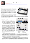
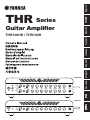
English
日本語
THR Series
Deutsch
Guitar Amplifier
I
I + II
II
MODERN
LEAD
BOOSTER
GAIN
MASTER
BASS
MIDDLE
TREBLE
PRESENCE
REVERB
VOLUME
INPUT I
BOOSTER
GAIN
MASTER
BASS
MIDDLE
TREBLE
PRESENCE
REVERB
VOLUME
INPUT II
Pусский
THR100HD
CRUNCH
CLEAN
SOLID
MODERN
LEAD
CRUNCH
CLEAN
SOLID
THR100H
MODERN
LEAD
CRUNCH
CLEAN
SOLID
BOOSTER
GAIN
MASTER
BASS
MIDDLE
TREBLE
PRESENCE
REVERB
VOLUME
INPUT
Português
Español
Italiano
Français
THR100HD / THR100H
Explanation of Graphical Symbols
Explication des symboles
The lightning flash with arrowhead symbol within an equilateral triangle is intended to alert the user to the presence of uninsulated
“dangerous voltage” within the product’s enclosure that may be of sufficient magnitude to constitute a risk of electric shock to persons.
L’éclair avec une flèche à l’intérieur d’un triangle équilatéral est destiné à attirer l’attention de l’utilisateur sur la présence d’une « tension
dangereuse » non isolée à l’intérieur de l’appareil, pouvant être suffisamment élevée pour constituer un risque d’électrocution.
The exclamation point within an equilateral triangle is intended to alert the user to the presence of important operating and maintenance (servicing) instructions in the literature accompanying the product.
Le point d’exclamation à l’intérieur d’un triangle équilatéral est destiné à attirer l’attention de l’utilisateur sur la présence d’instructions
importantes sur l’emploi ou la maintenance (réparation) de l’appareil dans la documentation fournie.
IMPORTANT SAFETY
INSTRUCTIONS
PRÉCAUTIONSCONCERNANT LA SÉCURITÉ
1
2
3
4
5
6
7
1
2
3
4
5
6
7
Read these instructions.
Keep these instructions.
Heed all warnings.
Follow all instructions.
Do not use this apparatus near water.
Clean only with dry cloth.
Do not block any ventilation openings. Install in accordance
with the manufacturer’s instructions.
8 Do not install near any heat sources such as radiators, heat
registers, stoves, or other apparatus (including amplifiers)
that produce heat.
9 Do not defeat the safety purpose of the polarized or grounding-type plug. A polarized plug has two blades with one wider
than the other. A grounding type plug has two blades and
a third grounding prong. The wide blade or the third prong
are provided for your safety. If the provided plug does not fit
into your outlet, consult an electrician for replacement of the
obsolete outlet.
10 Protect the power cord from being walked on or pinched
particularly at plugs, convenience receptacles, and the point
where they exit from the apparatus.
11 Only use attachments/accessories specified by the manufacturer.
12 Use only with the cart, stand, tripod, bracket,
or table specified by the manufacturer, or
sold with the apparatus. When a cart is used,
use caution when moving the cart/apparatus
combination to avoid injury from tip-over.
13 Unplug this apparatus during lightning storms
or when unused for long periods of time.
14 Refer all servicing to qualified service personnel. Servicing
is required when the apparatus has been damaged in any
way, such as power-supply cord or plug is damaged, liquid
has been spilled or objects have fallen into the apparatus, the
apparatus has been exposed to rain or moisture, does not
operate normally, or has been dropped.
WARNING
TO REDUCE THE RISK OF FIRE OR ELECTRIC SHOCK, DO NOT
EXPOSE THIS APPARATUS TO RAIN OR MOISTURE.
(UL60065_03)
2
Lire ces instructions.
Conserver ces instructions.
Tenir compte de tous les avertissements.
Suivre toutes les instructions.
Ne pas utiliser ce produit à proximité d’eau.
Nettoyer uniquement avec un chiffon propre et sec.
Ne pas bloquer les orifices de ventilation. Installer l’appareil
conformément aux instructions du fabricant.
8 Ne pas installer l’appareil à proximité d’une source de chaleur
comme un radiateur, une bouche de chaleur, un poêle ou
tout autre appareil (y compris un amplificateur) produisant de
la chaleur.
9 Ne pas modifier le système de sécurité de la fiche polarisée ou
de la fiche de terre. Une fiche polarisée dispose de deux broches
dont une est plus large que l’autre. Une fiche de terre dispose de
deux broches et d’une troisième pour le raccordement à la terre.
Cette broche plus large ou cette troisième broche est destinée à
assurer la sécurité de l’utilisateur. Si la fiche équipant l’appareil
n’est pas compatible avec les prises de courant disponibles,
faire remplacer les prises par un électricien.
10 Acheminer les cordons d’alimentation de sorte qu’ils ne soient
pas piétinés ni coincés, en faisant tout spécialement attention
aux fiches, prises de courant et au point de sortie de l’appareil.
11 Utiliser exclusivement les fixations et accessoires spécifiés
par le fabricant.
12 Utiliser exclusivement le chariot, le stand, le
trépied, le support ou la table recommandés
par le fabricant ou vendus avec cet appareil.
Si l’appareil est posé sur un chariot, déplacer
le chariot avec précaution pour éviter tout
risque de chute et de blessure.
13 Débrancher l’appareil en cas d’orage ou lorsqu’il doit rester
hors service pendant une période prolongée.
14 Confier toute réparation à un personnel qualifié. Faire réparer
l’appareil s’il a subi tout dommage, par exemple si la fiche
ou le cordon d’alimentation est endommagé, si du liquide a
coulé ou des objets sont tombés à l’intérieur de l’appareil, si
l’appareil a été exposé à la pluie ou à de l’humidité, si l’appareil
ne fonctionne pas normalement ou est tombé.
AVERTISSEMENT
POUR RÉDUIRE LES RISQUES D’INCENDIE OU DE DÉCHARGE
ÉLECTRIQUE, N’EXPOSEZ PAS CET APPAREIL À LA PLUIE OU À L’HUMIDITÉ.
(UL60065_03)
COMPLIANCE INFORMATION STATEMENT
(DECLARATION OF CONFORMITY PROCEDURE)
Responsible Party :
Address :
Telephone :
Type of Equipment :
Model Name :
Yamaha Corporation of America
6600 Orangethorpe Ave., Buena Park, Calif. 90620
714-522-9011
GUITAR AMPLIFIER
THR100HD/THR100H
This device complies with Part 15 of the FCC Rules.
Operation is subject to the following two conditions:
1) this device may not cause harmful interference, and
2) this device must accept any interference received including interference that may cause
undesired operation.
See user manual instructions if interference to radio reception is suspected.
*This applies only to products distributed by YAMAHA CORPORATION OF AMERICA.
(FCC DoC)
FCC INFORMATION (U.S.A.)
1. IMPORTANT NOTICE: DO NOT
MODIFY THIS UNIT!
This product, when installed as indicated
in the instructions contained in this manual, meets FCC requirements. Modifications not expressly approved by Yamaha
may void your authority, granted by the
FCC, to use the product.
2. IMPORTANT: When connecting this
product to accessories and/or another
product use only high quality shielded
cables. Cable/s supplied with this product MUST be used. Follow all installation
instructions. Failure to follow instructions
could void your FCC authorization to use
this product in the USA.
3. NOTE: This product has been tested
and found to comply with the requirements listed in FCC Regulations, Part 15
for Class “B” digital devices. Compliance
with these requirements provides a reasonable level of assurance that your use
of this product in a residential environment will not result in harmful interference
with other electronic devices. This equipment generates/uses radio frequencies
and, if not installed and used according
to the instructions found in the users
manual, may cause interference harmful
to the operation of other electronic de-
vices. Compliance with FCC regulations
does not guarantee that interference will
not occur in all installations. If this product is found to be the source of interference, which can be determined by turning
the unit “OFF” and “ON”, please try to
eliminate the problem by using one of the
following measures:
Relocate either this product or the device
that is being affected by the interference.
Utilize power outlets that are on different
branch (circuit breaker or fuse) circuits or
install AC line filter/s.
In the case of radio or TV interference, relocate/reorient the antenna. If the antenna
lead-in is 300 ohm ribbon lead, change
the lead-in to co-axial type cable.
If these corrective measures do not produce satisfactory results, please contact
the local retailer authorized to distribute
this type of product. If you can not locate
the appropriate retailer, please contact
Yamaha Corporation of America, Electronic Service Division, 6600 Orangethorpe
Ave, Buena Park, CA90620
The above statements apply ONLY to those
products distributed by Yamaha Corporation of America or its subsidiaries.
*This applies only to products distributed by YAMAHA CORPORATION OF AMERICA.
(class B)
3
This device complies with Part 15 of the FCC Rules. Operation is subject to the following two
conditions:
(1) this device may not cause harmful interference, and (2) this device must accept any interference received, including interference that may cause undesired operation.
This Class B digital apparatus complies with Canadian ICES-003.
Cet appareil numérique de la classe B est conforme à la norme NMB-003 du Canada.
For U.K. customers
If the socket outlets in the home are not suitable for the plug supplied with this appliance, it
should be cut off and an appropriate 3 pin plug fitted. For details, refer to the instructions described below.
Note
The plug severed from the mains lead must be destroyed, as a plug with bared flexible cord is
hazardous if engaged in a live socket outlet.
SPECIAL INSTRUCTIONS FOR U.K. MODEL
IMPORTANT NOTICE FOR THE UNITED KINGDOM
Connecting the Plug and Cord
WARNING: THIS APPARATUS MUST BE EARTHED IMPORTANT.
The wires in this mains lead are coloured in accordance with the following code:
GREEN-AND-YELLOW : EARTH
BLUE : NEUTRAL
BROWN : LIVE
As the colours of the wires in the mains lead of this apparatus may not correspond with the
coloured markings identifying the terminals in your plug proceed as follows:
The wire which is coloured GREEN-and-YELLOW must be connected to the terminal in the
or colored GREEN or
plug which is marked by the letter E or by the safety earth symbol
GREEN-and-YELLOW.
The wire which is coloured BLUE must be connected to the terminal which is marked with
the letter N or coloured BLACK.
The wire which is coloured BROWN must be connected to the terminal which is marked with
the letter L or coloured RED.
(3 wires)
“Laite on liitettävä suojamaadoituskoskettimilla
varustettuun pistorasiaan”
“Apparatet må tilkoples jordet stikkontakt”
“Apparaten skall anslutas till jordat uttag”
4
English
THR series Guitar Amplifier
THR100HD / THR100H
Owner’s Manual
Index
PRECAUTIONS............................................6
Features....................................................9
Package Contents.........................................9
Names And Functions.................................. 10
Connecting the Cabinet................................ 16
Power Connection...................................... 19
Using the Effect Loop.................................. 19
Using the Footswitch................................... 20
More Detailed Settings................................ 21
Troubleshooting......................................... 23
Specifications........................................... 24
Information for Users on Collection and Disposal of Old Equipment
This symbol on the products, packaging, and/or accompanying documents means that used electrical and electronic products should
not be mixed with general household waste.
For proper treatment, recovery and recycling of old products, please take them to applicable collection points, in accordance with
your national legislation and the Directives 2002/96/EC.
By disposing of these products correctly, you will help to save valuable resources and prevent any potential negative effects on human health and the environment which could otherwise arise from inappropriate waste handling.
For more information about collection and recycling of old products, please contact your local municipality, your waste disposal
service or the point of sale where you purchased the items.
[For business users in the European Union]
If you wish to discard electrical and electronic equipment, please contact your dealer or supplier for further information.
[Information on Disposal in other Countries outside the European Union]
This symbol is only valid in the European Union. If you wish to discard these items, please contact your local authorities or dealer and ask for the
correct method of disposal.
(weee_eu_en_01)
5
PRECAUTIONS
PLEASE READ CAREFULLY BEFORE PROCEEDING
Please keep this manual in a safe and handy place for future reference.
WARNING
Always follow the basic precautions listed below to avoid the possibility of serious injury
or even death from electrical shock, short-circuiting, damages, fire or other hazards. These
precautions include, but are not limited to, the following:
Power supply/Power cord
• Do not place the power cord near heat sources such
as heaters or radiators. Also, do not excessively
bend or otherwise damage the cord, or place heavy
objects on it.
• Only use the voltage specified as correct for the
device. The required voltage is printed on the name
plate of the device.
• Use only the supplied power cord/plug.
• Check the electric plug periodically and remove any
dirt or dust which may have accumulated on it.
• Be sure to connect to an appropriate outlet with a
protective grounding connection. Improper grounding can result in electrical shock. (→ page 19)
Do not open
• This device contains no user-serviceable parts.
Do not open the device or attempt to disassemble
or modify the internal components in any way. If it
should appear to be malfunctioning, discontinue
use immediately and have it inspected by qualified
Yamaha service personnel.
Water warning
• Do not expose the device to rain, use it near water
or in damp or wet conditions, place on it any containers (such as vases, bottles or glasses) containing
liquids which might spill into any openings. If any
liquid such as water seeps into the device, turn off
the power immediately and unplug the power cord
from the AC outlet. Then have the device inspected
by qualified Yamaha service personnel.
• Never insert or remove an electric plug with wet
hands.
6
Fire warning
• Do not put burning items, such as candles, on the
unit. A burning item may fall over and cause a fire.
If you notice any abnormality
• When one of the following problems occur, immediately turn off the power switch and disconnect the
electric plug from the outlet. Then have the device
inspected by Yamaha service personnel.
- The power cord or plug becomes frayed or damaged.
- It emits unusual smells or smoke.
- Some object has been dropped into the device.
- There is a sudden loss of sound during use of the
device.
CAUTION
Always follow the basic precautions listed below to avoid the possibility of physical injury
to you or others, or damage to the device or other property. These precautions include, but
are not limited to, the following:
Power supply/Power cord
• Do not connect the device to an electrical outlet
using a multiple-connector. Doing so can result in
lower sound quality, or possibly cause overheating
in the outlet.
• When removing the electric plug from the device
or an outlet, always hold the plug itself and not the
cord. Pulling by the cord can damage it.
• Remove the electric plug from the outlet when the
device is not to be used for extended periods of
time, or during electrical storms.
Location
• Do not place the device in an unstable position
where it might accidentally fall over.
• Do not place objects in front of the device’s air vent,
since this may prevent adequate ventilation of the
internal components, and possibly result in the
device overheating.
• Please do not use this device in a rack. Also, avoid
the following conditions when placing the device:
- Do not cover with a cloth or table cloth.
- Do not place the device on a rug or carpet, etc.
- Do not place the amplifier on its side or upside
down.
- Do not place in a confined area with poor ventilation.
Not following the above can cause heat to build up
inside of the device resulting in malfunction or fire.
Keep at least 5cm of space above, left and right
sides, and behind the device.
• Before moving the device, remove all connected
cables, to prevent damage to the cables or injury to
anyone who might trip over them.
• When setting up the product, make sure that the
AC outlet you are using is easily accessible. If some
trouble or malfunction occurs, immediately turn off
the power switch and disconnect the plug from the
outlet. Even when the power switch is turned off,
electricity is still flowing to the product at the minimum level. When you are not using the product for a
long time, make sure to unplug the power cord from
the wall AC outlet.
Connections
• Before connecting the device to other electronic
components, turn off the power for all components.
Before turning the power on or off for all components, set all volume levels to minimum.
• Be sure to set the volumes of all components at their
minimum levels and gradually raise the volume controls while playing the instrument to set the desired
listening level.
Handling caution
• Do not use the instrument/device or headphones for
a long period of time at a high or uncomfortable volume level, since this can cause permanent hearing
loss. If you experience any hearing loss or ringing in
the ears, consult a physician.
Yamaha cannot be held responsible for damage caused by improper use or modifications to the device, or data
that is lost or destroyed.
The name plate is located on the bottom of the unit.
Always turn the power off when the device is not in use.
7
NOTICE
To avoid the possibility of malfunction/ damage to
the product, damage to data, or damage to other
property, follow the notices below.
nHandling and Maintenance
• Do not use the device in the vicinity of a TV, radio,
stereo equipment, mobile phone, or other electric
devices. Otherwise, the device, TV, or radio may
generate noise. When you use the device along with
an application on your iPad, iPhone or iPod touch, we
recommend that you set “Airplane Mode” to “ON” on
that device in order to avoid noise caused by communication.
• Do not expose the device to excessive dust or
vibrations, or extreme cold or heat (such as in direct
sunlight, near a heater, or in a car during the day) to
prevent the possibility of panel disfiguration, damage
to the internal components or unstable operation.
(Verified operating temperature range: 5° – 40°C, or
41° – 104°F.)
• Do not place vinyl, plastic or rubber objects on the
device, since this might cause discoloration.
• When cleaning the device, use a soft and dry cloth. Do not use paint thinners, solvents, alcohol, cleaning
fluids, or chemical-impregnated wiping cloths.
8
Information
nAbout copyrights
• Copying of the software is strictly prohibited.
• This product incorporates and bundles computer
programs and contents in which Yamaha owns
copyrights or with respect to which it has license to
use others’ copyrights. Such copyrighted materials
include, without limitation, all computer software,
style files, MIDI files, WAVE data, musical scores
and sound recordings. Any unauthorized use of such
programs and contents outside of personal use is
not permitted under relevant laws. Any violation of
copyright has legal consequences. DON’T MAKE,
DISTRIBUTE OR USE ILLEGAL COPIES.
nAbout this manual
• The illustrations as shown in this manual are for instructional purposes only, and may appear somewhat
different from those on your device.
• Unless otherwise stated, all illustrations used in this
manual are of the THR100HD.
• Windows is a registered trademark of Microsoft®
Corporation in the United States and other countries.
• Apple, Mac and Macintosh are trademarks of Apple
Inc., registered in the U.S. and other countries.
• The company names and product names in this
manual are the trademarks or registered trademarks
of their respective companies.
Thank you for purchasing the Yamaha THR100HD/100H Guitar Amplifier.
In order to get the most out of this product, please read this Owner’s
Manual thoroughly before using. After you’ve finished reading the manual,
keep it in a safe place for future reference.
n Features
• Lightweight and compact amp head delivers the sound and tone, as well as volume, sound pressure level, and dynamics you would expect from professional quality tube amplifiers.
• Yamaha’s exclusive VCM Technology provides virtual modeling of both preamp and power
tube sections delivering a wider range of sound tailoring combinations for more detailed and
unique tone creation.
* What is VCM Technology?
An original physical modeling technology developed by Yamaha, VCM Technology reproduces the characteristics of
analog circuitry at a micro level to accurately reproduce the modeled equipment.
• Equipped with the same high-quality reverb as found on Yamaha’s high-end mixers.
• Newly developed Class-D power amplifier faithfully reproduces the specific operating characteristics of a tube amp, letting you experience authentic tube sound pressure level and dynamics.
• The THR100HD features a Dual Amplifier design that lets you create sound with two amplifiers
from a single head unit. This feature is also useful for providing separate amplification for two
electric guitars, letting two people perform simultaneously.
• A speaker simulator on both the LINE OUT and PHONES jacks replicates the dynamic, airy
tone of a speaker cabinet recorded in a studio with a microphone, letting you enjoy studio
quality tone through the direct line signal. Third-party IR data* for cabinet and microphone
types can also be used providing an even wider array of cabinet/micing combinations for
sound creation.
* IR data refers to speaker response data (impulse response).
n Package Contents
The following items are included in the package. Make sure that all items are present.
l THR100HD
• Guitar Amp x1
• Power cord x 1
• Exclusive Footswitch (5 switch) x1
• 5P DIN Footswitch Cable x1
• Owner’s Manual (this booklet) x 1
l THR100H
• Guitar Amp x1
• Power cord x 1
• Exclusive Footswitch (3 switch) x1
• 5P DIN Footswitch Cable x1
• Owner’s Manual (this booklet) x 1
9
Names And Functions
THR100HD
lFront Panel
I
MODERN
LEAD
GAIN
MASTER
BASS
MIDDLE
TREBLE
PRESENCE
REVERB
VOLUME
INPUT I
BOOSTER
GAIN
MASTER
BASS
MIDDLE
TREBLE
PRESENCE
REVERB
VOLUME
INPUT II
CLEAN
SOLID
I + II
II
BOOSTER
CRUNCH
MODERN
LEAD
CRUNCH
CLEAN
SOLID
w
e
r t
y
u
i
o
!0
!1
!2
!3
!4
q
lSignal Flow
External
Effector
L ch
Booster
AMP
Select
L ch
Reverb
Preamp
Speaker
Simulation
Poweramp
Speaker
Simulation
Booster
Preamp
Poweramp
Reverb
R ch
External
Effector
Mixer
R ch
THR100H
lFront Panel
MODERN
LEAD
BOOSTER
GAIN
MASTER
BASS
MIDDLE
TREBLE
PRESENCE
REVERB
VOLUME
INPUT
CRUNCH
CLEAN
SOLID
w
e
r t
y
u
i
o
!0
!1
!2
lSignal Flow
External
Effector
Booster
10
Preamp
Reverb
Poweramp
Speaker
Simulation
!3
!4
q
Names And Functions
When a guitar is connected to the INPUT I jack
I������� The signal from the guitar connected to
the INPUT I jack is sent to Amp I (top).
Only the output of Amp I (top) is sent to the
output circuit*.
* Output Circuit: Refers to the SPEAKER
OUT, LINEOUT, PHONES jacks.
II������ The signal from the guitar connected to
the INPUT I jack is sent to Amp II (bottom).
Only the output of Amp II (bottom) is sent
to the output circuit.
I+II��� The signal from the guitar connected to the
INPUT I jack is sent to both Amp I (top) and
Amp II (bottom). The outputs of both Amp I
and II are sent to the output circuit.
* Speaker and Cabinet
When the head and speaker sections of a guitar
amplifier are separate, the speaker section is
generally called the “cabinet”. As the number of
speakers installed in a cabinet varies among designs,
this manual will refer to the device that connects to
the SPEAKER OUT jack as a “cabinet”, and to the
individual speakers as a “speaker”.
q INPUT I/II
Connect the guitar to this jack.
On the THR100HD, the Amp Select switch e
assigns signal flow from INPUT I and INPUT
II to either Amp I (up position) or Amp II (lower
position).
If guitars are connected to the INPUT I and II
jacks
I������� The signal from the guitar connected to
the INPUT I jack is sent to Amp I (top).
Only the output of Amp I (top) is sent to the
output circuit.
II������ The signal from the guitar connected to the
INPUT II jack is sent to Amp II (bottom).
Only the output of Amp II (bottom) is sent
to the output circuit.
I+II��� The signal from the INPUT I jack is sent to
Amp I (top) and the signal from the INPUT
II jack is sent to Amp II (bottom). The
output of each Amp is sent to its respective
output circuit.
CAUTION
If you are only connecting one guitar to the
amp, use the INPUT I jack. Do not use the
INPUT II jack. Doing so may cause malfunction.
w
(Power Switch)
The unit’s power switch. When the power is
switched ON, the Amp Lamp e and the Front
Grill Lamp light.
CAUTION
If an abnormality is detected during operation, a protective function activates stopping
output from the SPEAKER OUT jacks. The
front grill lamp switches off and the power is
forced OFF. Refer to the “Troubleshooting”
section on page 23 for more information on
what to do when the protection function is
activated.
e [ THR100HD] Amp Select Switch/
Lamps
This switch selects the amplifier to be used in
respect to the INPUT I and INPUT II jacks q.
The lamp (I/II) for the selected amplifier lights.
e [THR100H] Power Lamp
Lights when the amp’s power is switched ON.
r Amp Type Selector
Selects the amp simulation type for the preamp
section.
MODERN: American Hard Rock stack amp tone
with rich low-end and sustain.
LEAD: Moderate preamp gain with the great
mid-range tone of a classic British amp.
11
Names And Functions
CRUNCH: Bright clear tone with the dynamic
distortion of a British combo amp.
CLEAN: Clear, rich clean tone characteristic of
an American combo amp.
SOLID: Clear tone typical of a solid-state amp.
*******************************************************************
n VCM Technology
The five virtual amp types found in the THR100 are
produced using Yamaha’s proprietary VCM Technology, a
newly developed amp modeling technology that faithfully
reproduces the operating characteristics of controls and
distinctive tone of each individual amp. VCM also lets you
switch the virtual power tubes in the power amp section via
the rear panel Tube Type Selector !5.
*******************************************************************
t BOOSTER Switch
Switches the Booster ON/OFF.
* When this switch is in the ON position, the
included foot switch can be used to switch the
booster function ON/OFF. (→ page 20)
yBOOSTER
Adjusts the amount of overdrive.
* Use the “THR HD_H Utility” application to set
the booster type. (→ page 21)
oBASS
!0MIDDLE
12
Adjusts the amount of gain in the power amp
section. Turn the knob clockwise to increase the
gain.
Adjusts the tonal character of the preamp
section. Turn the knob clockwise to enhance
high-range frequencies.
!2PRESENCE
Adjusts the high-range frequencies of the power
amp input section. Turn the knob clockwise to
enhance high-range frequencies that are higher
than the TREBLE control.
!3REVERB
Adjusts the send level to the Reverb circuit. Turn
the knob clockwise to increase the amount of
the effect.
* Turn the knob fully counter-clockwise to turn the
effect off.
* Use the “THR HD_H Utility” application to set
the reverb type. (→ page 21)
Adjusts the amount of gain in the preamp
section. Turn the knob clockwise to increase the
amount of preamp gain.
iMASTER
Adjusts the tonal character of the preamp
section. Turn the knob clockwise to enhance
mid-range frequencies.
!1TREBLE
uGAIN
Adjusts the tonal character of the preamp
section. Turn the knob clockwise to enhance
low-range frequencies.
!4VOLUME
Adjusts the final volume of the sound created
according to the panel control settings. This
setting is common for the SPEAKER OUT, LINE
OUT, and PHONES jacks.
Names And Functions
THR100HD
Rear Panel
l
!5
!6
!7 !8
POWER SECTION I
6V6
POWER SECTION II
6V6
CLASS
A
EL84
AB
6L6GC
6L6GC
4Ω
8Ω
16Ω
A
FSW
@2
I
LINE OUT
@7
II
AC IN
GND LIFT
25W
50W
100W
AB
EL34
EL34
USB TO
CLASS
EL84
@1
SPEAKER
KT88
KT88
@0
EFFECT LOOP
SEND
@6 @5
RETURN
@4
PHONES
SPEAKER OUT
1
IMPEDANCE 4~16Ω
CLASS 2 WIRING
@3
2
!9
THR100H
Rear Panel
l
POWER SECTION
!5
6V6
!6
!7 !8
4Ω
8Ω
16Ω
KT88
AB
6L6GC
EL34
USB
TO
FSW
EFFECT LOOP
SEND
RETURN
@1
PHONES
25W
50W
100W
@2
@7
LINE OUT
SPEAKER
CLASS
A
EL84
@0
AC IN
GND LIFT
SPEAKER OUT
IMPEDANCE 4~16Ω
CLASS 2 WIRING
@6 @5
@4
@3
!9
!5 POWER SECTION
Tube Type Selector
Selects the tube simulation type.
6V6: Tube used in small American combo amps
delivers distortion even at a low volume level.
EL84: Tube often used in British combo amps
delivers a soft drive.
KT88: This tube is used in a variety of amps
designed for everything from jazz to metal
and produces little distortion even at raised
volumes.
6L6GC: Tube often used in American amplifiers
produces a fat, resonant mid-range tone.
EL34: Tube often used in British amplifiers
produces great mid to high range projection.
* The THR100 amp does not incorporate physical
tubes in its design. Instead, it utilizes Yamaha’s
VCM Technology to faithfully reproduce the
characteristics of each of these tube types.
13
Names And Functions
!6 POWER SECTION
Tube Class Switch
Selects the operating type of the tube selected
with the Tube Type Selector !5.
CLASS A:
This system delivers excellent response and is
highly sensitive to touch, and playing nuances.
CLASS AB:
This system delivers more power with greater
volume.
!9 SPEAKER OUT
@0 Cooling Fan
!7SPEAKER
Impedance Switch
Sets the amplifier’s impedance to match the
specifications of the cabinet to be connected to
the SPEAKER OUT !9 jack.
On the THR100HD, this switch setting is
common for both SPEAKER OUT 1 and 2 jacks.
CAUTION
Before connecting the cabinet to the amplifier,
please read and fully understand the “Connecting the Cabinet” section (→ page 16) and
match the impedance setting to the cabinet’s
specifications. Using the wrong setting can
result in damage to the cabinet and to the amp.
!8SPEAKER
Power Output Switch
Sets the amplifier’s output wattage to match the
specifications of the cabinet to be connected to
the SPEAKER OUT !9 jack.
On the THR100HD, this setting is common for
both SPEAKER OUT 1 and 2 jacks.
CAUTION
Before connecting the cabinet to the amplifier, please read and fully understand the
“Connecting the Cabinet” section (→ page
16) and match the output wattage setting to
the cabinet’s specifications. Using the wrong
setting can result in damage to the cabinet
and to the amp.
14
Connects the cabinet to the amp.
On the THR100HD, jack 1 and jack 2 signals
differ according to the Amp Select switch e
setting and whether the SPEAKER OUT 2 jack
is connected to a cable. Please refer to the
“Connecting the Cabinet” section (→ page 16)
for more information.
Discharges heat from inside the amp to the
outside. Sensors inside the amp automatically
adjust fan speed.
CAUTION
Use the device in a location that has good
ventilation and keep the back open to prevent
heat from building up.
@1GND/LIFT
Connects the ground for the LINE OUT jack @2
to the amp’s chassis (GND) or disconnects the
ground (LIFT). If you experience hum or noise,
switching to LIFT may solve the problem.
@2 LINE OUT
Line-level balanced output for the signal that has
passed through the speaker simulation*.
* Use the “THR HD_H Utility” application to set
the speaker simulation type. (→ page 21)
On the THR100HD, Amp I output is sent to LINE
OUT I, and Amp II output is sent to LINE OUT II.
1: Ground (shield)
2: Hot (+)
3: Cold (-)
Names And Functions
@3PHONES
This is a stereo mini phone jack for headphones.
Like the LINE OUT jack @2, the signal for this
jack passes through the speaker simulator.
The jack is stereo but output to both L and R
terminals is the same (mono).
On the THR100HD, both LINE OUT I and II
jack signals are mixed and sent to both L and R
terminals.
* Connecting a plug to the PHONES jack stops
output to the SPEAKER OUT 1/2 jacks. Output to
the LINE OUT I/II jacks is not affected.
@4 EFFECT LOOP SEND/RETURN
These are the SEND and RETURN jacks for
an external effect loop. Please refer to the
“Using the Effect Loop” section (→ page 19) for
instructions on using the effect loop.
* The included footswitch can switch the effect
loop ON/OFF. (→ page 20)
@5 TO FSW (Footswitch)
Connector for the footswitch. Refer to the “Using
the Footswitch” section (→ page 20) for more
information.
@6USB
Use a USB cable (sold separately) to connect a
computer to the device.
* Refer to the “More Detailed Settings” section
(→ page 21) for more information.
@7 AC IN
Use the supplied AC power cord to connect the
device to an AC outlet. For safety, please be
sure to connect the ground.
15
Connecting the Cabinet
n Cabinet Specifications
Before connecting the cabinet, please check the
following two points.
l
l
Cabinet Power Rating
Cabinet Impedance
n Connections and Settings
Connect the amplifier to the cabinet using a
commercially available speaker cable (mono phone
to mono phone).
l Cabinet Power Rating
Set the Power Output switch on the amplifier’s rear
panel to the value that matches the power rating* of
the cabinet being connected to the amp.
* The power rating may be listed as “Power
Rating” or “Peak Power Rating” in the cabinet’s
specifications.
l Cabinet Impedance
Set the Impedance Switch on the amp’s rear panel to
match the impedance of the cabinet being connected
to the amp.
Always turn the amplifier power OFF before
making connections or disconnecting the
devices. Not doing so can result in electric
shock.
l
Never use an instrument (guitar) cable.
Using an instrument cable can damage the
speakers and the amp.
Connecting the THR100H to a THRC112 (Output
Power: 150W, Impedance: 8Ω).
THR100H
100W
Power Output Switch
CAUTION
Using the wrong setting can damage the
speakers and the amp.
16
l
l Connection Example 1
8Ω
Impedance Switch
CAUTION
l
Settings on the Yamaha THRC212 Cabinet
will change power rating and impedance
requirements for the cabinet. Please read
the THRC212 Owner’s Manual carefully and
make the appropriate settings.
l
When connecting multiple cabinets make
the proper settings after calculating the
overall system’s permissible input and total
impedance. Also, keep the impedance of
the connected devices within a range of 4Ω
to 16Ω.
THRC112
Connecting the Cabinet
l Connection Example 2
l Connection Example 3
Connecting the THR100HD to a THRC112 (Output
Power: 150W, Impedance: 8Ω).
Connecting the THR100HD to a pair of THRC112
cabinets (Output Power: 150W, Impedance: 8Ω).
CAUTION
THR100HD
INPUT
Always use the SPEAKER OUT 1 jack when
connecting a single cabinet to the amp.
I
THR100HD
INPUT
100W
8Ω
I
8Ω
100W
THRC112
THRC112
THR100HD Amp Select Switch Setting and the
Signal Output to the Cabinet
l Amp Select Switch = I
Amp I (top) sound is output.
l Amp Select Switch = II
Amp II (bottom) sound is output.
l Amp Select Switch = I+II
Amp I (top) sound and Amp II (bottom) sound is output.
Rated output for the THR100HD is 50W
when a 4Ω cabinet is connected to the
SPEAKER OUT 1 jack.
Amp I
Sound
THRC112
Amp II
Sound
THR100HD Amp Select Switch Setting and the
Signal Output to the Cabinets
l Amp Select Switch = I
Amp I (top) sound is sent to the SPEAKER OUT 1 jack.
No signal is sent to the SPEAKER OUT 2 jack.
l Amp Select Switch = II
Amp II (bottom) sound is sent to the SPEAKER OUT 2
jack. No signal is sent to the SPEAKER I jack.
l Amp Select Switch = I+II
Amp I (top) → SPEAKER OUT 1 jack, Amp II (bottom)
→ SPEAKER OUT 2 jack, each amp has its own
output.
17
Connecting the Cabinet
l Connection Example 4
l Connection Example 5
Connecting the THR100HD to the THRC212 (Output
Power: 150W, Impedance: 8Ω).
Connecting the THR100HD to a pair of THRC112
cabinets (Output Power: 150W, Impedance: 8Ω) and
playing two guitars connected to the amp.
THR100HD
THR100HD
INPUT
INPUT
I
I
Guitar
1
II
100W
8Ω
8Ω
100W
Guitar
2
THRC212
THRC112
DUAL
Amp II
Sound
Amp I
Sound
The two speakers installed in the THRC212 cabinet
operate independently.
The THR100HD’s Amp Select Switch setting and
signal output to the cabinet are the same as in
Example 3.
Amp I
(Guitar 1)
Sound
THRC112
Amp II
(Guitar 2)
Sound
The THRC112 connected to the SPEAKER OUT 1
jack produces the sound from Amp I (Guitar 1), while
the THRC112 connected to the SPEAKER OUT 2
jack produces the sound from Amp II (Guitar 2).
The THR100HD’s Amp Select Switch setting and
signal output to the cabinet are the same as in
Example 3.
Rated output for the THR100HD is 50W + 50W when the SPEAKER OUT 1, 2
jacks each have a separate cabinet connected.
18
Power Connection
Connect the supplied power cord to the rear panel
AC IN connector, then connect the other end to an
AC outlet.
Rear Panel
AC IN Connector
Power Cord (supplied)
CAUTION
For safe operation, always connect the ground
wire.
Using the Effect Loop
Use the EFFECT LOOP SEND/RETURN jacks to
connect an external effector. (Diagram 1)
You can switch the Effect Loop ON/OFF using the
included footswitch. (→ page 20)
* The external effects circuit is set to parallel at
factory but can be switched to serial using the
“THR HD_H Utility” application. (→ page 21)
Diagram 1
On the THR100HD, the SEND/RETURN jacks are
stereo (TRS), with Amp I assigned to the Tip and
Amp II assigned to the Ring. (Diagram 2)
To connect an external effect to Amp I only, use a
monaural phone cable.
To connect external effects to Amp I and Amp II
separately, use an insert cable (stereo → mono x2)
as shown in the diagram below. (Diagram 3)
Diagram 2
Diagram 3
Tipe (L): Amp I
Ring (R): Amp II
Sleeve (G): GND
L
IN
OUT
Left
Side
L
R
R
Right
Side
Amp I Effector
Effector
Amp II Effector
Monaural Phone Jack
19
Using the Footswitch
Some of the amp’s functions and switch settings can be controlled with your feet using the supplied footswitch.
l THR100HD
q
w
e
r
t
y
t
y
l THR100H
e
r
q [THR100HD] AMP I/II
t FX LOOP
Switches the front panel Amp Select switch
setting between AMP I and II.
w [THR100HD] Amp I+II
Switches the front panel Amp Select switch to
I+II (lamp lit).
Press the switch again to enable the Amp I/II
switch q setting.
eBOOSTER
Switches the BOOSTER function ON/OFF. Both
Amp I and Amp II are switched simultaneously.
* Only switches the BOOSTER function ON/OFF
for the amp that has its front panel BOOSTER
switch in the ON position. The switch has no
effect if both the Amp I and Amp II front panel
BOOSTER switches are in the OFF position.
rREVERB
20
Switches the reverb effect ON/OFF. Both Amp I
and Amp II are switched simultaneously.
Switches the signal from the rear panel EFFECT
LOOP SEND/RETURN jack ON/OFF. Both Amp
I and Amp II are switched simultaneously.
y TO AMP
Use the supplied footswitch cable to connect
this terminal to the TO FSW terminal on the rear
panel of the amp.
CAUTION
Always switch the amplifier’s power OFF
before connecting the cable.
More Detailed Settings
n Connect to a Computer
•Connecting the amplifier to a computer may
block the computer’s sound input/output.
Switch to another device as needed.
Connecting a computer to the amplifier’s USB jack
provides access to the following functions.
l
Edit amp settings with the “THR HD_H Utility”
l
Update the unit’s system firmware.
editor.
A commercially available USB cable is required to
connect a computer to the amplifier.
Computer
USB Cable (sold separately)
n Using the “THR HD_H
Utility”
The “THR HD_H Utility” is a specialized application
that allows the user to perform detailed settings that
cannot be accessed with the panel controls.
l What You Can Do with the
“THR HD_H Utility”
Set the built-in BOOSTER type (3 types).
Set the Effect Loop circuit type (serial/parallel).
l Set the built-in REVERB type (4 types).
l Set the noise gate level (OFF/1/2/3).
l Set speaker simulation settings. Set the
l
l
speaker simulation for each of the amplifier
types.
Precautions in regard to using the USB jack
Make sure you follow the points below when connecting a computer to the THR USB jack. Failing to
do so may result in the computer or the THR freezing or shutting down, as well as corruption or even
loss of data. If the device or computer does freeze,
restart the application or computer.
CAUTION
•Use only an AB type USB cable less than three
(3) meters in length. USB 3.0 cables are not
compatible.
•Be sure to wake the computer from suspended/sleep/ standby mode before connecting a
computer to the USB jack.
•Always quit all applications that are running
on the computer before connecting or disconnecting the USB cable and set the volume
output on the computer to its minimum level.
•Wait at least 6 seconds between connecting
or disconnecting the USB cable.
l To Use the “THR HD_H
Utility”
Before connecting your computer to the amplifier,
you will need to download and install the “THR HD_
H Utility” and the required driver from the Yamaha
web site below.
http://download.yamaha.com/
* Check the above website for information on
system requirements.
l Driver Installation
1. Access the following website and download the
latest version of the “Yamaha Steinberg USB
Driver”, the file will decompress and open.
http://download.yamaha.com/
* Check the above website for information on
system requirements.
* Before using, please understand that even if
your computer meets all operating requirements,
the software may not function correctly.
21
More Detailed Settings
* The “Yamaha Steinberg USB Driver” may be
updated without notice. Please visit the above
website for the latest details and updates.
2. Install the “Yamaha Steinberg USB Driver” in
your computer. Refer to the Installation Guide
that is included in the downloaded file.
l Installing “THR HD_H Utility”
1. Access the following web site and download the
“THR HD_H Utility”.
http://download.yamaha.com/
* Check the above website for information on
system requirements.
n Updating the Amplifier’s
Firmware
Updates for the amp’s internal firmware provide
improvements to the device.
To update your THR100HD/100H, please follow the
procedure below.
* Before proceeding, install the latest version of the
“Yamaha Steinberg USB Driver”. (→ page 21)
l Update Procedure
1. Visit the following website and download the “THR
HD_H Updater”.
2. Start the downloaded file and follow the instructions that appear in the display to install the “THR
HD_H Utility”.
http://download.yamaha.com/
3. Refer to the “THR HD_H Utility” Owner’s Manual
or the Help Guide for information on settings and
operation of the “THR HD_H Utility”.
2. Expand the downloaded file (compressed ZIP file).
l Using the “THR HD_H Utility”
1. Use a USB cable to connect a computer to the
THR100HD/100H. (→ page 21)
2. Turn the THR100HD/100H power ON, launch the
“THR HD_H Utility”.
3. Use the “THR HD_H Utility” to perform various
settings. Edited settings are stored in the amplifier.
* Please refer to the “THR HD_H Utility” Owner’s
Manual for more information on detailed settings
and how to use the application.
22
* Please refer to the URL provided above for
system requirements.
3. Run the “THR HD_H Updater”.
* Refer to the “THR HD_H Updater” User’s Manual
for detailed instructions.
Troubleshooting
No power
Is the power cord properly connected?
(→ page 19)
l
No sound
Is the instrument’s volume control turned up?
l
Is the Amp Select switch properly set?
l
Is the cabinet properly connected? (→ page
16)
l
l
l
l
Are the GAIN, MASTER, or VOLUME controls
set to “0”?
l
l
l
THR100HD: Is the instrument connected to
the INPUT II jack? If only a single instrument
is being used, it must be connected to the
INPUT I jack.
l
l
1) The front grill lamp is not lit
Is an instrument properly connected to the
INPUT jack?
l
l
Stopped producing sound while
playing
If you have selected the CLEAN amp type, no
sound is produced if the tone controls are set
to “0”.
Are a pair of headphones connected to the
PHONES jack?
Is the cable used to connect the instrument to
the amp damaged?
Is the cable used to connect the amp to the
cabinet damaged?
The thermal protection system has activated,
terminating output to the SPEAKER OUT jack.
Allow the amplifier to cool down then switch
the power ON again. If the thermal protection
system activates again, unplug the power cord
and contact the Yamaha dealer from whom
you purchased the device.
The tip end of the speaker cable is grounded
or touched by static electricity causing a short.
Check the speaker cable and after eliminating
the cause, switch the power OFF and then ON
again. If the protection circuit activates again,
immediately turn the power OFF, disconnect
the power cord, and contact the Yamaha
dealer from whom you purchased the device.
2) The power is OFF
l
The internal circuitry may not be functioning
properly. Immediately turn the power OFF,
disconnect the power cord, and contact the
Yamaha dealer from whom you purchased the
device.
Is the Effect Loop mode set to a serial
connection with the “THR HD_H Utility”?
In the serial connection mode, no sound is
produced if the loop is active without an effect
connected to the EFFECT LOOP SEND/
RETURN jacks. (→ page 21)
23
Specifications
Digital Section
• Built-in Amp Simulations
SOLID, CLEAN, CRUNCH, LEAD, MODERN
• Built-in Effects
BOOSTER (WHITE/GREEN/AMBER*)
REVERB (SPRING/PLATE/ROOM/HALL*)
NOISE GATE*
SPEAKER SIMULATION*
* Only available in the “THR HD_H Utility.”
INPUT : -10 dBu/1MΩ
Rated Output
THR100HD
SPEAKER OUT 1 only: 100W (50W at 4Ω)
SPEAKER OUT 1+2 : 50W+50W
THR100H
100W
Power Source
Controller/Switch
THR100HD
AMP I, II Common: Power Switch, Amp Select
Switch, Impedance Switch, Power Rating
Switch, GND/LIFT Switch
AMP I, II One Each: Amp Type Selector,
BOOSTER Switch, BOOSTER, GAIN, MASTER, BASS, MIDDLE, TREBLE, PRESENCE,
REVERB, VOLUME, POWER SECTION Selector, CLASS Switch
THR100H
Power Switch, Amp Type Selector, BOOSTER
Switch, BOOSTER, GAIN, MASTER, BASS,
MIDDLE, TREBLE, PRESENCE, REVERB,
VOLUME, POWER SECTION Selector, CLASS
Switch, Impedance Switch, Power Rating
Switch, GND/LIFT Switch
Connections
Input Level
THR100HD
INPUT I, II (Standard Monaural Phone Jack)
PHONES (Stereo Mini Phone Jack)
SPEAKER OUT 1/2 (Standard Monaural Phone Jack)
EFFECT LOOP SEND/RETURN (Standard
Stereo Phone Jack)
LINE OUT 1/2 (XLR Male)
TO FSW (5P DIN)
USB 2.0 (Type B)
AC IN (3P)
THR100H
INPUT (Standard Monaural Phone Jack)
PHONES (Stereo Mini Phone Jack)
SPEAKER OUT (Standard Monaural Phone Jack)
EFFECT LOOP SEND/RETURN (Standard
Stereo Phone Jack)
LINE OUT (XLR Male)
TO FSW (5P DIN)
USB 2.0 (Type B)
AC IN (3P)
AC100V - 240V, 50/60 Hz
Power Consumption
THR100HD: 60 W
THR100H: 40 W
Dimensions (W x D x H)
THR100HD: 445×248×125 mm
THR100H: 445×248×95 mm
Weight
THR100HD: 4.2 kg
THR100H: 3.6 kg
Accessories
THR100HD
• Power cord x 1
• Exclusive Footswitch (5 switch) x1
• 5P DIN Footswitch Cable x1
• Owner’s Manual (this booklet) x 1
THR100H
• Power cord x 1
• Exclusive Footswitch (3 switch) x1
• 5P DIN Footswitch Cable x1
• Owner’s Manual (this booklet) x 1
* Specifications and appearance may change without notice.
24
ZQ05310-1
版次 : R0
Printed in China