1
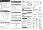
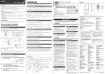
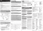
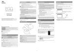
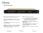
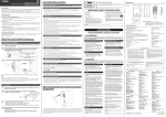
ZC58000 EN PORTABLE PA SYSTEM Connecting microphones, instruments, and audio devices to the mixer 4 Applying Reverb Connect desired devices, such as a microphone, or an instrument to the input jack of the mixer. Refer to the illustration on the mixer shown below or the connection example of the cover panel of the accessory compartment. Owner’s Manual 3 The LED lights when REVERB is on. Long Position the REVERB TYPE/TIME control to the desired reverb type and time (length). 6|SUBWOOFER OUT jack This is for connection to a powered subwoofer, and outputs a mono signal. If this jack is in use, the low frequencies below 120Hz to the SPEAKERS L/R jacks will be cut. The output level is linked to that of the MASTER LEVEL control (C). Short Use the REVERB control to adjust the reverb amount of the corresponding channel. If necessary, repeat steps 2 and 3 to determine the optimum reverb setting. Main Features Getting sound out of the system • 600 watts power amplifier for versatility in a wide variety of performance applications. • 10-inch two-way bass-reflex type speakers for high-quality, powerful sound. • 10-channel mixer features four mono mic/line and three stereo line input channels to support a wide range of inputs. • Yamaha’s high-quality SPX reverb, providing optimum processing for instruments or vocals. • Feedback Suppressor, which automatically cuts and prevents undesirable feedback noise. • USB connector for convenient digital connection with an iPod/iPhone, and allows charging of the device. • Independent three-band equalizer on each channel for tonal adjustment and sound control. 5 7 REVERB FOOT SW jack 1 3 This is for connection to an unlatchedtype footswitch such as the Yamaha FC5—useful for solo performers, since you can toggle the reverb on and off as needed with your foot. 2 Connect the included power cord. First, connect it to the mixer’s AC IN connector, then to a power outlet. Connecting the speakers and the mixer Slide the mixer’s lock in the direction of the arrow (shown below), and then remove it from the speaker. Turn the mixer’s LEVEL controls (white knobs) and MASTER LEVEL control (red knob) to the minimum (zero). Also, set the equalizer controls (green knobs) to the center “D” or “MUSIC” position. Caution • Use a genuine Apple Dock Connector USB Cable for the iPod/iPhone connection. • Please do not use a USB hub. NOTE If you connect an iPhone, incoming calls or emails may cause a notification sound to be output. In order to prevent this, we recommend setting the iPhone’s Airplane mode to “on.” Use the included speaker cables to connect the speakers. ) PHANTOM (CH1/2) switch /LED When this switch is on, the LED lights indicating that phantom power is available for channels 1 and 2. Turn this switch on to supply power to condenser microphones or a DI (direct box). 1 Mic/Line input jacks (channels 1-4) Equalizer Connect microphones, guitars, electronic musical instruments or audio equipment. Channels 3 and 4 provide combo jacks that support both XLR and phone plugs. XLR Caution phone Follow the important precautions below, in order to prevent noise and possible damage to external devices and the unit when you operate this switch. • Be sure to leave this switch off if you do not need phantom power, or when you connect a device that does not support phantom power to channels 1 or 2. • Do not connect/disconnect a cable to/from channels 1 and 2 while this switch on. • Turn the LEVEL control of the channels 1 and 2 to the minimum before operating this switch. 2 MIC/LINE switches (channels 1-4) For low-level signals (including microphones), set the switch to the MIC (N) position. For high-level signals (including electronic instruments and audio equipment), set the switch to the LINE (O) position. 3 Hi-Z switch (channel 4) This switch is used when connecting a device directly to the mixer without a DI (direct box)—for example, instruments with passive pickups, such as an acoustic-electric guitar or electric bass without battery. This function is effective only for the phone jack input. 4 Line (stereo) input jacks (channels 5/6, 7/8, 9/10) 7 Connect your iPod/iPhone using a USB cable to play music and charge the iPod/iPhone. Use the LEVEL control of channels 9/10 to adjust the volume, since the music signals are mixed to those channels. This connector supplies 5V power to the connected USB device. This connector does not support digital playback from USB devices other than the iPod/iPhone. For playback of such devices, use appropriate stereo mini or RCA pin connectors. 8 SPEAKERS L/R jacks Mixer Controls and Functions 6 Quick Start Guide Press down the REVERB switch to turn it on. Turning the control toward the right lengthens the time of the selected reverb type. Thank you and congratulations on your purchase of the Yamaha STAGEPAS 600i Portable PA System. The STAGEPAS 600i is an all-in-one PA system, consisting of two speakers and a powered mixer. In order to get the most out of your new STAGEPAS 600i and its sophisticated functions, we suggest you read through this manual thoroughly. Also keep it in a safe place for future reference. 1 1 9 USB connector These are for connection to a powered speaker for monitoring purposes, and output a mix of the signals from channels 1 to 9/10. You can adjust the output level using the MONITOR OUT control (!). If only the L (MONO) jack is used, the signals from the L and R channels are mixed and output. The STAGEPAS 600i features a built-in reverb processor that is in the same league as our famed SPX effect processor series. This reverb lets you simulate the acoustics of different performance environments, such as concert halls and small clubs, and add warm, natural ambience to your vocals or instrument performance. 2 Introduction 5 MONITOR OUT jacks Set the MIC/LINE switch to the MIC (N) position for microphone connection, and to the LINE (O) position for connection of an instrument or audio device. Connect line-level devices such as electronic instruments, acoustic-electric guitars, CD players, and portable audio players. These jacks support phone, RCA-pin, and stereo-mini plugs. RCA-pin stereo-mini ! MONITOR OUT control NOTE For the channel 7/8 input, if both phone and RCA-pin jacks are used at the same time, the phone jack will take priority. For the channel 9/10 input, if both phone and stereo mini jacks are used at the same time, the stereo mini jack will take priority. The signal from the device connected to another jack will be muted. The music signals from iPod/iPhone (9) are always mixed to channels 9/10. Determines the signal level output from the MONITOR OUT jacks (5). The MASTER LEVEL control does not affect the MONITOR OUT signal. @ Equalizer controls (HIGH, MID, LOW) 2 Open the cover panel attached to the other speaker, and then remove the box from inside the accessory compartment. Two speaker cables and one power cord are included in the box. 8 Turn on the power of the connected sound source (if applicable), then the mixer. This three-band equalizer adjusts the channel’s high, mid, and low frequency bands. Setting the control to the “D” position produces a flat response in the corresponding band. Turning the control clockwise boosts the selected band. If you start getting feedback, turn the control back slightly. 6 1 2 The POWER LED lights. 9 manual (this booklet), and an optional microphone can conveniently be stored in the accessory compartment. Connect the speakers and the mixer. Connect the mixer’s SPEAKERS jack to the speakers’ input jack using the included speaker cables. As shown in the illustration below, make sure to insert the speaker cables all the way inside until secure. 10While playing your instrument or singing into the microphone, use the LEVEL control to adjust the volume of the corresponding channel. Determines the reverb type and its length. Turning the control toward the right lengthens the time of the selected reverb type. HALL: Simulated reverb of a large space, such as a concert hall. PLATE: Simulated metal plate reverb, producing a more hardedged and bright sound. ROOM: Simulated acoustic ambience of a small room. ECHO: Echo effect suitable for vocals. % REVERB controls (channels 1-4) & If you hear the sound and the volume seems appropriate, setup is complete. If not, please refer to the check list in the “Troubleshooting” section on the back of this booklet. ! $ # A Setting the switch to ST (STEREO) (N) will assign the signals from the L and R channels to each left and right speaker and output each signal. Setting the switch to MONO (O) will mix the output of different L and R sources to output the same signal to both the left and right speakers. For keyboards with mono output, guitars, or other non-stereo sound sources, when the switch is set to MONO, the stereo jacks can be conveniently used as multiple mono jacks. & LEVEL meter Making optimum volume settings The LEVEL meter shows the level of output signal from the SPEAKERS L/R jacks. When the volume is too loud If used at a high volume so that the LIMITER LED flashes continuously, the internal power amplifier section is being excessively overloaded and may malfunction. Reduce the output level with the MASTER LEVEL control so that the indicator flashes only briefly on the highest transient peaks. When the volume is too soft SPEAKERS jack Caution Use only the included speaker cables. Use of other cables may result in heat generation, or short circuiting. Turn the LEVEL control to the minimum (zero). Set the MIC/LINE switch to the MIC (N) position, then slowly raise the LEVEL control until the desired volume is reached. B C D F Determines the amount of reverb for each channel when the REVERB switch (#) is on. connected sound source (such as an instrument or audio device). Turn the LEVEL control to the minimum (zero). Set the MIC/LINE switch to the LINE (O) position, then slowly raise the LEVEL control until the desired volume is reached. ( ^ % * D NOTE To avoid any loud, unexpected noise from the speaker, first turn off the power to the mixer, then the Input jack 9 @ ^ ST/MONO switches (channels 5/6, 7/8, 9/10) 11Use the MASTER LEVEL control to adjust the overall volume. E ) $ REVERB TYPE/TIME control Set the MASTER LEVEL control to the “D” position. 8 7 When this switch is on, the LED lights indicating that you can apply reverb. This switch is off when you turn on the mixer. (Unlike other switches, this switch cannot be locked.) NOTE After the box is removed, loose items, such as the included power cord, speaker cables, owner’s 3 5 4 # REVERB switch/LED Accessory compartment Cover panel 3 Caution * POWER LED This LED lights when the power is turned on by pressing the power switch. ( FEEDBACK SUPPRESSOR switch/LED When this switch is on, the LED lights indicating that feedback is automatically suppressed. (This utilizes a seven-band notch filter. When this switch or the power switch is off, the notch filter will be reset.) A LEVEL controls Use these controls to adjust the volume for each channel. To reduce noise, set any LEVEL controls on unused channels to the minimum. B MASTER EQ (equalizer) control Use this control to adjust the overall sound frequency balance. The center position “MUSIC” is a basic setting and if you turn the control counterclockwise, this creates an optimum setting for speech, cutting unneeded low range frequencies. If you turn the control clockwise, it creates an optimum setting for playback of sound sources, since the low range is boosted. If you turn the control clockwise further, the LED lights indicating that the bass boost function turns on, giving you even more powerful bass tone. C MASTER LEVEL control Determines the volume of the signal output from the SPEAKERS L/R jacks. This allows you to adjust the overall volume without changing the relative volume balance among the various channels. D Vents These are the vents for the cooling fan inside the mixer. Do not block the vents when in use. E AC IN jack Connect the included power cord here. F (power) switch For turning the power of the mixer on (O) and off (N). Caution apidly turning the unit on and off in succession may R cause it to malfunction. After turning the unit off, wait for about 5 seconds before turning it on again. Specifications Troubleshooting Do not open General Specifications 100V - 240V 50Hz/60Hz Maximum Output Power (SPEAKERS L/R) Power does not turn on. Did you firmly and securely connect the power cord? Are the vents of the mixer blocked? Since inadequate ventilation can result in overheating the mixer, the power may be turned off automatically to protect from overheating. Secure the ventilation for cooling, then turn on the power again. Is the MIC/LINE switch of the corresponding channel set to MIC? If the input level from the source is high, setting the MIC/LINE switch to MIC may result in distorted sound. Set the switch to LINE position. No sound is heard. Is the volume of the connected device too high? Lower the volume of the external device. Did you connect the mixer’s SPEAKERS jacks and the speakers’ input jacks using the proper speaker cables? -3 dB, +1 dB @ 40 Hz-20 kHz, 1 W Output/4Ω (without EQ and SP EQ) (SPEAKERS L/R) -3 dB, +1 dB @ 40 Hz-20 kHz, +4 dBu 10 kΩ Load (MONITOR OUT) iPod touch (1st, 2nd, 3rd, and 4th generation), iPod classic, iPod nano (2nd, 3rd, 4th, 5th, and 6th generation), iPhone 4S, iPhone 4, iPhone 3GS, iPhone 3G, iPhone For updated information, check the Yamaha Pro Audio website (http://www.yamahaproaudio.com/). 0.5 % @20 Hz-20 kHz, +11 dBu 10 kΩ (MONITOR OUT) Hum & Noise (Rs= 150 Ω, MIC/LINE switch=MIC) -113 dBu Equivalent input noise (CH1-4) -58 dBu Residual output noise (SPEAKERS L/R) Enclosure -70 dB between input channels +30 V (CH1, 2) LF: 10” (25 cm) Cone HF: 1.4” (3.56 cm) Compression Driver 25.4 kg (56 lbs) (Speaker 10.8 kg x 2 + Mixer 3.8 kg) Crossover Frequency Package Contents Is a speaker other than the included speaker (MODEL 600S) connected to the mixer’s SPEAKERS jacks? Please connect the included speaker (MODEL 600S). Are the LEVEL controls of all relevant channels and/or the MASTER LEVEL control set too low? Input Terminals CH IN 1-2 XLR XLR CH IN 3-4 CH IN 5/6 CH IN 7/8 Are the equalizer controls raised or lowered too much? Set the equalizer controls to the center position. CH IN 9/10 MIC/LINE Input Impedance Source Impedance 3 kΩ 150 Ω Mics 3 kΩ 150 Ω Mics MIC LINE MIC Input Level Max. before Clipping Sensitivity Nominal -56 dBu -35 dBu -10 dBu -30 dBu -9 dBu +16 dBu -56 dBu -35 dBu -10 dBu LINE -30 dBu -9 dBu +16 dBu MIC -29 dBu -4 dBu 150 Ω Lines (Hi-Z 10 kΩ) -50 dBu Connector Type XLR-3-31 XLR Combo LINE -24 dBu -3 dBu +22 dBu Phone - 10 kΩ 150 Ω Lines -24 dBu -3 dBu +22 dBu Phone* Phone - 10 kΩ 150 Ω Lines -24 dBu -3 dBu +22 dBu Phone* Pin - 10 kΩ 150 Ω Lines -24 dBu -3 dBu +22 dBu RCA Pin Phone - 10 kΩ 150 Ω Lines -24 dBu -3 dBu +22 dBu Phone* Mini - 10 kΩ 150 Ω Lines -24 dBu -3 dBu +22 dBu Stereo Mini Output Characteristics Is the speaker properly outputting the high-frequency range signals? If not, check the “Protective circuit (poly switch)” note in the Notice section. iPod/iPhone is not recognized Is your iPod/iPhone charged? If your iPod/iPhone has not been charged, it may take some time to be recognized by the mixer. Make sure that your iPod/iPhone is connected to the mixer and wait until it is sufficiently charged. Output Level Output Terminals Output Impedance Load Impedance SPEAKERS OUT [L,R] <0.1 Ω 4 Ω Speakers MONITOR OUT [L,R] 600 Ω 10 kΩ Lines SUBWOOFER OUT 150 Ω 10 kΩ Lines -3 dBu 0 dBu=0.775 Vrms, 0 dBV=1 Vrms Max. before Clipping Typ at THD+N 10% Dynamic Connector Type 62.5 W 230 W 280 W 340 W Phone* +4 dBu +20 dBu - - Phone* +17 dBu - - Phone* Nominal Phone*: Unbalanced Specifications and descriptions in this owner’s manual are for information purposes only. Yamaha Corp.reserves the right to change or modify products or specifications at any time without prior notice. Since specifications, equipment or options may not be the same in every locale, please check with your Yamaha dealer. Dimensions * If any specific problem should persist, please contact your Yamaha dealer. Unit: mm Mixer Speaker 135 Lock lever 2 Lock Screw holes for the Mic Stand Adapter BMS-10A (optional) 96 109 Block Diagram HA EQ BA LEVEL REVERB R * Use of the stand should refer to stand manufacturer’s instructions. EQ SUM AD SUM LEVEL HIGH MID LOW MIC/LINE(-26dB) + - [-56 –+16dBu] [-50 –+22dBu] HA EQ LEVEL HIGH MID LOW DA AMP L MASTER LEVEL AD DA SUM BA BA BA HIGH MID LOW EQ INPUT (CH5/6) EQ LEVEL L(MONO) ST/MONO REVERB ON/OFF FOOT SWITCH BA R MONITOR OUT R BA EQ BA HIGH INPUT (CH7/8) MID LOW L LEVEL BA EQ BA SUM EQ BA ST/MONO SUM HIGH L/R MID LOW R INPUT (CH9/10) EQ L R USB CONTROLLER 5V 1A LEVEL BA [-24 –+22dBu] USB (iPod/iPhone) * Please keep this manual in a safe place for future reference. DA DA ST/MONO WARNING MONITOR OUT BA [-24 –+22dBu] R PLEASE READ CAREFULLY BEFORE PROCEEDING SUBWOOFER OUT (MONO) REVERB PRECAUTIONS SPEAKERS OUT DA BA [-24 –+22dBu] AMP BA Hi-Z(1MΩ) L DA (-1) REVERB ON/OFF SUM MIC/LINE(-26dB) Hi-Z AD R REVERB COMBO INPUT (CH4) L BA LIMITER HA [-56 –+16dBu] [-50 –+22dBu] MASTER LEVEL - FEEDBACK SUPPRESSOR + REVERB REVERB INPUT (CH3) HIGH PHANTOM (+30V) LOW COMBO MIC/LINE(-26dB) MASTER EQ DSP [-56 –+16dBu] SP EQ (FIXED) - MID L Pole diameter 34.8 - 35.2 + INPUT (CH1-2) 335 2 144 197 1 Release 319 Move the lock lever down to lock to the stand. 354 2 50° Attach the speaker to the speaker stand with the lock lever moved up (release position). 348 1 545 Attaching a speaker to a speaker stand Always follow the basic precautions listed below to avoid the possibility of serious injury or even death from electrical shock, short-circuiting, damages, fire or other hazards. These precautions include, but are not limited to, the following: Power supply/Power cord • Do not place the power cord near heat sources such as heaters or radiators, and do not excessively bend or otherwise damage the cord, place heavy objects on it, or place it in a position where anyone could walk on, trip over, or roll anything over it. • Only use the voltage specified as correct for the mixer. The required voltage is printed on the name plate of the mixer. • Use only the supplied power cord. If you intend to use the device in an area other than in the one you purchased, the included power cord may not be compatible. Please check with your Yamaha dealer. • Check the electric plug periodically and remove any dirt or dust which may have accumulated on it. • Be sure to connect to an appropriate outlet with a protective grounding connection. Improper grounding can result in electrical shock. • Before connecting the device to other devices, turn off the power for all devices. Before turning the power on or off for all devices, set all volume levels to minimum. • For the SPEAKERS jacks of the mixer, use only the included MODEL 600S speakers and speaker cables. Use of other types of speakers and cables may result in damage, or even fire. Maintenance • Remove the power plug from the AC outlet when cleaning the device. Explanation of Graphical Symbols The lightning flash with arrowhead symbol within an equilateral triangle is intended to alert the user to the presence of uninsulated “dangerous voltage” within the product’s enclosure that may be of sufficient magnitude to constitute a risk of electric shock to persons. CAUTION RISK OF ELECTRIC SHOCK DO NOT OPEN The exclamation point within an equilateral triangle is intended to alert the user to the presence of important operating and maintenance (servicing) instructions in the literature accompanying the product. CAUTION: TO REDUCE THE RISK OF ELECTRIC SHOCK, DO NOT REMOVE COVER (OR BACK). NO USER-SERVICEABLE PARTS INSIDE. REFER SERVICING TO QUALIFIED SERVICE PERSONNEL. The above warning is located on the bottom of the mixer. IMPORTANT SAFETY INSTRUCTIONS 1. 2. 3. 4. 5. 6. 7. Read these instructions. Keep these instructions. Heed all warnings. Follow all instructions. Do not use this apparatus near water. Clean only with dry cloth. Do not block any ventilation openings. Install in accordance with the manufacturer’s instructions. 8. Do not install near any heat sources such as radiators, heat registers, stoves, or other apparatus (including amplifiers) that produce heat. 9. Do not defeat the safety purpose of the polarized or grounding-type plug. A polarized plug has two blades with one wider than the other. A grounding type plug has two blades and a third grounding prong. The wide blade or the third prong are provided for your safety. If the provided plug does not fit into your outlet, consult an electrician for replacement of the obsolete outlet. 10.Protect the power cord from being walked on or pinched particularly at plugs, convenience receptacles, and the point where they exit from the apparatus. 11. Only use attachments/accessories specified by the manufacturer. 12.Use only with the cart, stand, tripod, bracket, or table specified by the manufacturer, or sold with the apparatus. When a cart is used, use caution when moving the cart/ apparatus combination to avoid injury from tip-over. 13.Unplug this apparatus during lightning storms or when unused for long periods of time. 14.Refer all servicing to qualified service personnel. Servicing is required when the apparatus has been damaged in any way, such as power-supply cord or plug is damaged, liquid has been spilled or objects have fallen into the apparatus, the apparatus has been exposed to rain or moisture, does not operate normally, or has been dropped. WARNING TO REDUCE THE RISK OF FIRE OR ELECTRIC SHOCK, DO NOT EXPOSE THIS APPARATUS TO RAIN OR MOISTURE. (UL60065_03) Handling caution CAUTION 90° (Horizontal)/60° (Vertical) 10 kΩ (Hi-Z 1 MΩ) Phone The high sounds and low sounds are unbalanced. Is the POWER LED flashing continuously? If the internal power amplifier section is excessively overloaded, the amplifier will be muted for protection. The mixer will automatically reset itself after a while. 129 dB SPL (Measured peak IEC noise@1m) Coverage Angle Input Characteristics Is the PHANTOM switch set to on when using a microphone that requires phantom power? For channels 7/8, are both phone and RCA-pin jacks connected at the same time? Or, for channels 9/10, are both phone and stereo mini jacks connected at the same time? The phone jack has priority for channels 7/8 and the stereo mini jack has priority for 9/10. 55 Hz-20 kHz (-10 dB) Maximum Output Level 35 W (Idle), 100 W (1/8 Power) Is the volume of the connected device too low? Raise the volume of the external device. Is the POWER LED flashing at intervals? There may be a short in the speaker cable or the connection may be faulty. Check that the speaker cable is not scratched and is connected properly to the mixer, then reapply the power. Frequency Range Power Consumption Is the MIC/LINE switch of the corresponding channel set to LINE? Turn the LEVEL control to the minimum (zero). Set the switch to the MIC position, then slowly raise the LEVEL control. Did you use the included speaker cables? If you use a commercially-available speaker cable with a metal-housing connector, the cable will be shorted when the connector touches other metal, resulting in no sound being produced. 2.8 kHz STAGEPAS 600i (includes two MODEL 600S Speakers and a Powered Mixer), Cover Panel, Power Cord (2m), two Speaker Cables (6m), 12 Non-Skid Pads, Owner’s Manual (this booklet) Connections • When one of the following problems occur, immediately turn off the power switch and disconnect the electric plug from the outlet. Then have the device inspected by Yamaha service personnel. - The power cord or plug becomes frayed or damaged. - It emits unusual smells or smoke. - Some object has been dropped into the instrument. - There is a sudden loss of sound during use of the device. • If this mixer should be dropped or damaged, immediately turn off the power switch, disconnect the electric plug from the outlet, and have the device inspected by qualified Yamaha service personnel. Speaker Unit Weight Fire warning If you notice any abnormality 2 way bass-reflex type Phantom Voltage • Do not expose the device to rain, use it near water or in damp or wet conditions, or place on it any containers (such as vases, bottles or glasses) containing liquids which might spill into any openings. If any liquid such as water seeps into the device, turn off the power immediately and unplug the power cord from the AC outlet. Then have the device inspected by qualified Yamaha service personnel. • Never insert or remove an electric plug with wet hands. • Do not put burning items, such as candles, on the unit. A burning item may fall over and cause a fire. Speakers (MODEL 600S) Crosstalk (1 kHz) Sound is not loud enough Water warning Supported iPod/iPhone models (as of August 2012) Total Harmonic Distortion Is the speaker cable or the power cord located near the input cables? Please keep it away from the input cables. Did you firmly and securely connect the speaker cables? ±15 dB HIGH:8 kHz shelving MID: 2.5 kHz peaking LOW:100 Hz shelving Frequency Response Are the LEVEL controls of all relevant channels and/or the MASTER LEVEL control set too high? Power shuts down suddenly. Input Channel Equalization 340 W + 340 W/4 Ω @Dynamic at 1 kHz 280 W+280 W/4Ω @10 % THD at 1 kHz 230 W+230 W/4Ω @1 % THD at 1 kHz Sound is distorted or noise is produced • This device contains no user-serviceable parts. Do not open the device or attempt to disassemble the internal parts or modify them in any way. If it should appear to be malfunctioning, discontinue use immediately and have it inspected by qualified Yamaha service personnel. Power Requirement • Do not use the device in a confined, poorly-ventilated location. Make sure that there is adequate space between the mixer, or the speaker fitted with the mixer, and surrounding walls or other devices: at least 30cm at the sides, 30cm behind and 30cm above. Inadequate ventilation can result in overheating, possibly causing damage to the device(s), or even fire. • If you lay the speaker flat on its side or like a stage monitor, make sure to remove the mixer first. • Do not hold the bottom of the speaker when transporting or moving it. In doing so, you may pinch your hands under the speaker, and result in injury. • Do not place the device in a location where it may come into contact with corrosive gases or salt air. Doing so may result in malfunction. • Before moving the device, remove all connected cables. • When setting up the mixer, make sure that the AC outlet you are using is easily accessible. If some trouble or malfunction occurs, immediately turn off the power switch and disconnect the plug from the outlet. Even when the power switch is turned off, electricity is still flowing to the product at the minimum level. When you are not using the product for a long time, make sure to unplug the power cord from the wall AC outlet. Always follow the basic precautions listed below to avoid the possibility of physical injury to you or others, or damage to the device or other property. These precautions include, but are not limited to, the following: Power supply/Power cord • When removing the electric plug from the device or an outlet, always hold the plug itself and not the cord. Pulling by the cord can damage it. • Remove the electric plug from the outlet when the device is not to be used for extended periods of time, or during electrical storms. Location • Do not place the device in an unstable position. Unless the device is securely affixed, do not install it in a location where it might fall, even if the surface is level. • Do not block the vents. This mixer has ventilation holes at the top and sides to prevent the internal temperature from becoming too high. In particular, do not place the mixer on its side or upside down. Inadequate ventilation can result in overheating, possibly causing damage to the mixer, or even fire. • Do not insert your fingers or hands in any gaps or openings on the vents or panel of the mixer and the ports of the speaker. • Avoid inserting or dropping foreign objects (paper, plastic, metal, etc.) into any gaps or openings on the vents or panel of the mixer and the ports of the speaker. If this happens, turn off the power immediately and unplug the power cord from the AC outlet. Then have the device inspected by qualified Yamaha service personnel. • Do not rest your weight on the device or place heavy objects on it, and avoid use excessive force on the buttons, switches or connectors. • Do not use the speakers for a long period of time at a high or uncomfortable volume level, since this can cause permanent hearing loss. If you experience any hearing loss or ringing in the ears, consult a physician. • Do not operate the device if the sound is distorting. Prolonged use in this condition could cause overheating and result in fire. • Do not pull on any attached cable, such that of a microphone. Doing so may cause the speaker to topple, and result in damage or in injury. Yamaha cannot be held responsible for damage caused by improper use or modifications to the device, or data that is lost or destroyed. PA_en_1 FCC INFORMATION (U.S.A.) 1. IMPORTANT NOTICE: DO NOT MODIFY THIS UNIT! This product, when installed as indicated in the instructions contained in this manual, meets FCC requirements. Modifications not expressly approved by Yamaha may void your authority, granted by the FCC, to use the product. 2. IMPORTANT: When connecting this product to accessories and/or another product use only high quality shielded cables. Cable/s supplied with this product MUST be used. Follow all installation instructions. Failure to follow instructions could void your FCC authorization to use this product in the USA. 3. NOTE: This product has been tested and found to comply with the requirements listed in FCC Regulations, Part 15 for Class “B” digital devices. Compliance with these requirements provides a reasonable level of assurance that your use of this product in a residential environment will not result in harmful interference with other electronic devices. This equipment generates/uses radio frequencies and, if not installed and used according to the instructions found in the users manual, may cause interference harmful to the operation of other electronic devices. Compliance with FCC regulations does not guarantee that interference will not occur in all installations. If this product is found to be the source of interference, which can be determined by turning the unit “OFF” and “ON”, please try to eliminate the problem by using one of the following measures: Relocate either this product or the device that is being affected by the interference. Utilize power outlets that are on different branch (circuit breaker or fuse) circuits or install AC line filter/s. In the case of radio or TV interference, relocate/reorient the antenna. If the antenna lead-in is 300 ohm ribbon lead, change the lead-in to co-axial type cable. If these corrective measures do not produce satisfactory results, please contact the local retailer authorized to distribute this type of product. If you can not locate the appropriate retailer, please contact Yamaha Corporation of America, Electronic Service Division, 6600 Orangethorpe Ave, Buena Park, CA90620 The above statements apply ONLY to those products distributed by Yamaha Corporation of America or its subsidiaries. * This applies only to products distributed by YAMAHA CORPORATION OF AMERICA. 이 기기는 가정용(B급) 전자파적합기기로서 주로 가정에서 사용하는 것을 목적으로 하며, 모든 지역에서 사용할 수 있습니다. (class B) In Finland: Laite on liitettävä suojamaadoituskoskettimilla varustettuun pistorasiaan. In Norway: Apparatet må tilkoples jordet stikkontakt. In Sweden: Apparaten skall anslutas till jordat uttag. (class b korea) (class I hokuo) Notice To avoid the possibility of malfunction or damage to the product, follow the notices below. Handling and Maintenance • Do not expose the device to excessive dust or vibration, or extreme cold or heat (such as in direct sunlight, near a heater, or in a car during the day), in order to prevent the possibility of panel disfiguration, unstable operation, or damage to the internal components. • Do not place vinyl, plastic or rubber objects on the device, since this might discolor the panel. • When cleaning the device, use a dry and soft cloth. Do not use paint thinners, solvents, cleaning fluids, or chemical-impregnated wiping cloths. • Condensation can occur in the device due to rapid, drastic changes in ambient temperature—when the device is moved from one location to another, or air conditioning is turned on or off, for example. Using the device while condensation is present can cause damage. If there is reason to believe that condensation might have occurred, leave the device for several hours without turning on the power until the condensation has completely dried out. • Avoid setting all equalizer controls and LEVEL knobs to their maximum. Depending on the condition of the connected devices, doing so may cause feedback and may damage the speakers. • When turning on the AC power in your audio system, always turn on the mixer LAST, to avoid speaker damage due to the noise. When turning the power off, the mixer should be turned off FIRST for the same reason. • Protective circuit (poly switch) All full-range loudspeakers are fitted with a self-resetting poly switch that protects the high-frequency driver from damage caused by excessive power. If a loudspeaker cabinet loses high-frequency output, immediately remove power from the unit and wait for two to three minutes. This should be long enough to allow the poly switch to reset. Reapply power and check the performance of the highfrequency driver before continuing, with the power reduced to a level that does not cause the poly switch to interrupt the signal. • Interference from cell phones Using a cell phone near the speaker system can induce noise. If this occurs, move the cell phone further away from the speaker system. • Air blowing out of the bass reflex ports is normal, and often occurs when the speaker is handling program material with heavy bass content. • Always turn the power off when the device is not in use. Connectors • XLR-type connectors are wired as follows (IEC60268 standard): pin 1: ground, pin 2: hot (+), and pin 3: cold (-). Information About functions/data bundled with the device • iPod TM , iPhone TM iPhone, iPod, iPod classic, iPod nano, and iPod touch are trademarks of Apple Inc., registered in the U.S. and other countries. “Made for iPod” and “Made for iPhone” mean that an electronic accessory has been designed to connect specifically to iPod or iPhone respectively, and has been certified by the developer to meet Apple performance standards. Apple is not responsible for the operation of this device or its compliance with safety and regulatory standards. Please note that the use of this accessory with iPod or iPhone may affect wireless performance. About this manual • The illustrations as shown in this manual are for instructional purposes only, and may appear somewhat different from those on your device. • The company names and product names in this manual are the trademarks or registered trademarks of their respective companies. Information for Users on Collection and Disposal of Old Equipment This symbol on the products, packaging, and/or accompanying documents means that used electrical and electronic products should not be mixed with general household waste. For proper treatment, recovery and recycling of old products, please take them to applicable collection points, in accordance with your national legislation and the Directives 2002/96/EC. By disposing of these products correctly, you will help to save valuable resources and prevent any potential negative effects on human health and the environment which could otherwise arise from inappropriate waste handling. For more information about collection and recycling of old products, please contact your local municipality, your waste disposal service or the point of sale where you purchased the items. [For business users in the European Union] If you wish to discard electrical and electronic equipment, please contact your dealer or supplier for further information. [Information on Disposal in other Countries outside the European Union] This symbol is only valid in the European Union. If you wish to discard these items, please contact your local authorities or dealer and ask for the correct method of disposal. (weee_eu) For details of products, please contact your nearest Yamaha representative or the authorized distributor listed below. IMPORTANT NOTICE FOR THE UNITED KINGDOM Connecting the Plug and Cord WARNING: THIS APPARATUS MUST BE EARTHED IMPORTANT. The wires in this mains lead are coloured in accordance with the following code: GREEN-AND-YELLOW : EARTH BLUE BROWN : NEUTRAL : LIVE As the colours of the wires in the mains lead of this apparatus may not correspond with the coloured markings identifying the terminals in your plug proceed as follows: The wire which is coloured GREEN-and-YELLOW must be connected to the terminal in the plug which is marked by the letter E or by the safety earth symbol or colored GREEN or GREEN-and-YELLOW. The wire which is coloured BLUE must be connected to the terminal which is marked with the letter N or coloured BLACK. Yamaha Pro Audio global web site http://www.yamahaproaudio.com/ The wire which is coloured BROWN must be connected to the terminal which is marked with the letter L or coloured RED. Yamaha Manual Library http://www.yamaha.co.jp/manual/ (3 wires) C.S.G., Pro Audio Division ©2012 Yamaha Corporation 208MWHD*.*-01A0 Printed in China