1
Instruction Manual
Designed for Fan and Pump Applications
Thank you for purchasing our FRENIC-Eco series of inverters.
• This product is designed to drive a three-phase induction motor. Read through this instruction manual and
be familiar with the handling procedure for correct use.
• Improper handling might result in incorrect operation, a short life, or even a failure of this product as well as
the motor.
• Deliver this manual to the end user of this product. Keep this manual in a safe place until this product is
discarded.
• For how to use an optional device, refer to the installation and instruction manuals for that optional device.
Fuji Electric FA Components & Systems Co., Ltd.
Fuji Electric Corp. of America
INR-SI47-1225-E
Copyright © 2007 Fuji Electric FA Components & Systems Co., Ltd.
All rights reserved.
No part of this publication may be reproduced or copied without prior written permission from Fuji Electric FA
Components & Systems Co., Ltd.
All products and company names mentioned in this manual are trademarks or registered trademarks of their
respective holders.
The information contained herein is subject to change without prior notice for improvement.
Preface
Thank you for purchasing our FRENIC-Eco series of inverters.
This product is designed to drive a three-phase induction motor for fan and pump applications. Read through this
instruction manual and be familiar with proper handling and operation of this product.
Improper handling might result in incorrect operation, a short life, or even a failure of this product as well as the
motor.
Have this manual delivered to the end user of this product. Keep this manual in a safe place until this product is
discarded.
Listed below are the other materials related to the use of the FRENIC-Eco. Read them in conjunction with this
manual as necessary.
• FRENIC-Eco User's Manual
• RS-485 Communication User's Manual
• Catalog
• Relay Output Card "OPC-F1-RY" Instruction Manual
• Mounting Adapter for External Cooling "PB-F1" Installation Manual
• Panel-mount Adapter "MA-F1" Installation Manual
• FRENIC Loader Instruction Manual
The materials are subject to change without notice. Be sure to obtain the latest editions for use.
Safety precautions
Read this manual thoroughly before proceeding with installation, connections (wiring), operation, or maintenance
and inspection. Ensure you have sound knowledge of the device and familiarize yourself with all safety
information and precautions before proceeding to operate the inverter.
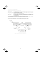
Safety precautions are classified into the following two categories in this manual.
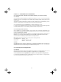
Failure to heed the information indicated by this symbol may lead to
dangerous conditions, possibly resulting in death or serious bodily injuries.
Failure to heed the information indicated by this symbol may lead to
dangerous conditions, possibly resulting in minor or light bodily injuries
and/or substantial property damage.
Failure to heed the information contained under the CAUTION title can also result in serious consequences.
These safety precautions are of utmost importance and must be observed at all times.
i
Application
• FRENIC-Eco is designed to drive a three-phase induction motor. Do not use it for single-phase motors
or for other purposes.
Fire or an accident could occur.
• FRENIC-Eco may not be used for a life-support system or other purposes directly related to the human
safety.
• Though FRENIC-Eco is manufactured under strict quality control, install safety devices for applications
where serious accidents or material losses are foreseen in relation to the failure of it.
An accident could occur.
Installation
• Install the inverter on a nonflammable material such as metal.
Otherwise fire could occur.
• Do not place flammable matter nearby.
Doing so could cause fire.
• Do not support the inverter by its terminal block cover during transportation.
Doing so could cause a drop of the inverter and injuries.
• Prevent lint, paper fibers, sawdust, dust, metallic chips, or other foreign materials from getting into the
inverter or from accumulating on the heat sink.
Otherwise, a fire or an accident might result.
• Do not install or operate an inverter that is damaged or lacking parts.
Doing so could cause fire, an accident or injuries.
• Do not get on a shipping box.
• Do not stack shipping boxes higher than the indicated information printed on those boxes.
Doing so could cause injuries.
ii
Wiring
• When wiring the inverter to the power source, insert a recommended molded case circuit breaker
(MCCB) or residual-current-operated protective device (RCD)/a ground fault circuit
interrupter(GFCI)(with overcurrent protection) in the path of power lines. Use the devices within the
recommended current range.
• Use wires in the specified size.
Otherwise, fire could occur.
• Do not use one multicore cable in order to connect several inverters with motors.
• Do not connect a surge suppressor to the inverter's output (secondary) circuit.
Doing so could cause fire.
• Ground the inverter in compliance with the national or local electric code.
Otherwise, electric shock could occur.
• Qualified electricians should carry out wiring.
• Be sure to perform wiring after turning the power OFF.
Otherwise, electric shock could occur.
• Be sure to perform wiring after installing the inverter body.
Otherwise, electric shock or injuries could occur.
• Ensure that the number of input phases and the rated voltage of the product match the number of
phases and the voltage of the AC power supply to which the product is to be connected.
Otherwise fire or an accident could occur.
• Do not connect the power source wires to output terminals (U, V, and W).
Doing so could cause fire or an accident.
• Generally, control signal wires are not enforced- insulated. If they accidentally touch any of live parts in
the main circuit, their insulation coat may break for any reasons. In such a case, an extremely high
voltage may be applied to the signal lines. Make a complete remedy to protect the signal line from
contacting any hot high voltage lines.
Otherwise, an accident or electric shock could occur.
• Wire the three-phase motor to terminals U, V, and W of the inverter, aligning phases each other.
Otherwise injuries could occur.
• The inverter, motor and wiring generate electric noise. Take care of malfunction of the nearby sensors
and devices. To prevent the motor from malfunctioning, implement noise control measures.
Otherwise an accident could occur.
iii
Operation
• Be sure to install the terminal block cover and the front cover before turning the power ON. Do not
remove the covers while power is applied.
Otherwise electric shock could occur.
• Do not operate switches with wet hands.
Doing so could cause electric shock.
• If the retry function has been selected, the inverter may automatically restart and drive the motor
depending on the cause of tripping.
(Design the machinery or equipment so that human safety is ensured after restarting.)
• If the stall prevention function (current limiter), automatic deceleration, and overload prevention control
have been selected, the inverter may operate at an acceleration/deceleration time or frequency
different from the commanded ones. Design the machine so that safety is ensured even in such cases.
Otherwise an accident could occur.
key on the keypad is effective only when the keypad operation is enabled with function code
• The
F02 (= 0, 2 or 3). When the keypad operation is disabled, prepare an emergency stop switch separately
for safe operations.
Switching the run command source from keypad (local) to external equipment (remote) by turning ON
the "Enable communications link" command (LE) or "Switch run command 2/1" command (FR2/FR1),
disables the
key. To enable the
key for an emergency stop, select the STOP key priority with
function code H96 (= 1 or 3).
• If an alarm reset is made with the Run command signal turned ON, a sudden start will occur. Ensure that
the Run command signal is turned OFF in advance.
Otherwise an accident could occur.
• If you enable the "Restart mode after momentary power failure" (Function code F14 = 3, 4, or 5), then
the inverter automatically restarts running the motor when the power is recovered.
(Design the machinery or equipment so that human safety is ensured after restarting.)
• If you set the function codes wrongly or without completely understanding this instruction manual and
the FRENIC-Eco User's Manual, the motor may rotate with a torque or at a speed not permitted for the
machine.
An accident or injuries could occur.
• Do not touch the inverter terminals while the power is applied to the inverter even if the inverter stops.
Doing so could cause electric shock.
iv
• Do not turn the main circuit power (circuit breaker) ON or OFF in order to start or stop inverter operation.
Doing so could cause failure.
• Do not touch the heat sink because they become very hot.
Doing so could cause burns.
• Setting the inverter to high speeds is easy. Before changing the frequency (speed) setting, check the
specifications of the motor and machinery.
• The brake function of the inverter does not provide mechanical holding means.
Injuries could occur.
Setting control switches
• Before setting up any internal control switches, turn OFF the power and wait more than five minutes for
models of 30HP for 208V, 40HP for 460V or below, or ten minutes for models of 40HP for 208V, 50HP
for 460V or above. Make sure that the LED monitor and charging lamp (on models of 40HP for 208V,
50HP for 460V or above) are turned OFF. Further, make sure, using a multimeter or a similar
instrument, that the DC link bus voltage between the terminals P (+) and N (-) has dropped below the
safe voltage (+25 VDC).
Otherwise electric shock could occur.
Maintenance and inspection, and parts replacement
• Turn the power OFF and wait for at least five minutes for models of 30HP for 208V, 40HP for 460V or
below, or ten minutes for models of 40HP for 208V, 50HP for 460V or above, before starting inspection.
Further, check that the LED monitor and charging lamp (on models of 40HP for 208V, 50HP for 460V or
above) are unlit and that the DC link bus voltage between the P (+) and N (-) terminals is lower than 25
VDC.
Otherwise, electric shock could occur.
• Maintenance, inspection, and parts replacement should be made only by qualified persons.
• Take off the watch, rings and other metallic objects before starting work.
• Use insulated tools.
Otherwise, electric shock or injuries could occur.
Disposal
• Treat the inverter as an industrial waste when disposing of it.
Otherwise injuries could occur.
Others
• Never attempt to modify the inverter.
Doing so could cause electric shock or injuries.
GENERAL PRECAUTIONS
Drawings in this manual may be illustrated without covers or safety shields for explanation of detail parts.
Restore the covers and shields in the original state and observe the description in the manual before
starting operation.
v
Conformity with Low Voltage Directive in the EU
If installed according to the guidelines given below, inverters marked with CE can be considered to be compliant
with the Low Voltage Directive 73/23/EEC.
1. Be sure to earth the grounding terminal zG. Use an earth wire sized more than that of the power wires
used in the power dispatch system. Do not use a residual-current-operated protective device (RCD)* or a
ground fault circuit interrupter(GFCI)* as a sole mechanism of electric shock protection.
*With overcurrent protection.
2. Use an MCCB, RCD/GFCI or MC in conformity with EN or IEC standards.
3. When an RCD/GFCI is used for protection of electric shock caused by a direct or indirect contact to the
live parts, insert a type B RCD/GFCI in input lines (primary) of the inverter for the 3-phase 208 V or 460 V
power source.
4. Use inverters in an environment that does not exceed pollution degree 2. If inverters are to be used in an
environment with pollution degree 3 or 4, place them in an enclosure of IP54 or above.
5. To protect human body from an electric shock caused by a contact to live parts, install inverters, AC
reactor and input /output filter in the enclosure of IP2X. In the case where human body easily contacts to
live parts, a top panel of the enclosure should be IP4X or higher.
6. Do not directly connect a copper wire to the grounding terminal. Use a crimp terminal with tin or equivalent
plating to connect the earth wire.
7. When using inverters at an altitude of more than 6600ft(2000 m), note that the basic insulation applies to
the insulation degree of the control circuitry. At an altitude of more than 9800ft(3000 m), inverters cannot
be used.
vi
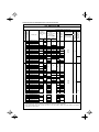
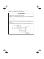
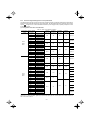
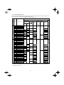
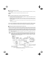
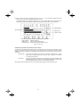
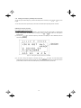
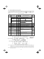
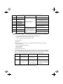
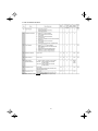
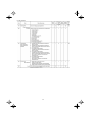
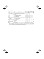
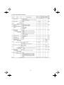
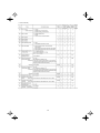
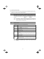
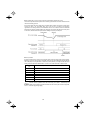
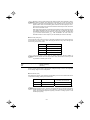
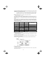
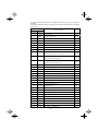
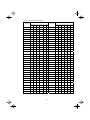
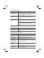
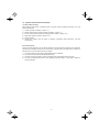
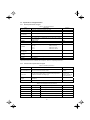
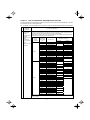
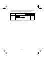
Conformity with Low Voltage Directive in the EU (continued)
Three-phase 460 V
FRN001F1S-2U
FRN002F1S-2U
FRN003F1S-2U
FRN005F1S-2U
FRN007F1S-2U
FRN010F1S-2U
FRN015F1S-2U
FRN020F1S-2U
FRN025F1S-2U
FRN030F1S-2U
FRN040F1S-2U
FRN050F1S-2U
FRN060F1S-2U
FRN075F1S-2U
FRN100F1S-2U
FRN125F1S-2U
FRN001F1S-4U
FRN002F1S-4U
FRN003F1S-4U
FRN005F1S-4U
FRN007F1S-4U
FRN010F1S-4U
FRN015F1S-4U
FRN020F1S-4U
FRN025F1S-4U
FRN030F1S-4U
FRN040F1S-4U
FRN050F1S-4U
FRN060F1S-4U
FRN075F1S-4U
FRN100F1S-4U
FRN125F1S-4U
FRN150F1S-4U
FRN200F1S-4U
FRN250F1S-4U
FRN300F1S-4U
FRN350F1S-4U
FRN400F1S-4U
FRN450F1S-4U
FRN500F1S-4U
FRN600F1S-4U
FRN700F1S-4U
FRN800F1S-4U
FRN900F1S-4U
10
20
40
50
75
100
150
175
200
250
350
W/
DCR
20
2.5
30
75
100
125
150
175
200
250
300
350
-
500
5
10
15
20
30
40
50
75
100
125
175
200
250
300
5
10
15
20
30
40
50
60
75
100
125
150
200
500
600
800
1000
1200
W/o
DCR
2.5
4.0
10
16
25
35
50
70
35x2
50x2
70x2
6.0
10
16
25
35
50
16x2
95
50x2
95x2
240
-
2.5
2.5
4.0
6.0
10
4.0
6.0
10
16
25
35
70
95
50x2
70x2
150
185
240
150x2
2.5
2.5
6.0
10
16
25
35
50
25x2
95
50x2
70x2
95x2
240
6.0
16
25
95x2
120x2
2.5
2.5
4.0
6.0
4.0
6.0
10
16
16
10
25
35
50
25x2
16
35
185x2
240x2
185x3
240x3
185x4
70
25x2
95
0.25
to
0.75
2.5
50x2
2.5
-
25
70x2
185
240
150x2
150x2
185x2
240x2
185x3
240x3
185x4
240x4
185x2
240x2
50x2
-
35
35
50
25x2
95
120
70x2
240
120x2
16x2
25x2
Europe type
terminal block
Aux. fan power
supply [R1, T1]
W/o
DCR
15
Control circuit
Aux. control power
supply [R0, T0]
W/
DCR
DC reactor
[P1, P(+)]
1
2
3
5
7
10
15
20
25
30
40
50
60
75
100
125
1
2
3
5
7
10
15
20
25
30
40
50
60
75
100
125
150
200
250
300
350
400
450
500
600
700
800
900
Inverter type
Main power
2
input *
[L1/R, L2/S, L3/T]
Inverter’s
grounding [zG]
2
Nominal applied
motor (HP)
Recommended wire size (mm2)
MCCB or
1
RCD/GFCI *
Rated current
(A)
Inverter outputs *
[U, V, W]
Three-phase 208 V
Power supply voltage
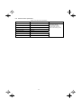
8. Use the wires listed in EN60204-1.
0.25
to
0.75
2.5
2.5
240x3
240x4
*1 The frame size and model of the MCCB or RCD/GFCI (with overcurrent protection) will vary, depending on the
power transformer capacity. Refer to the related technical documentation for details.
*2 The recommended wire size for main circuits is for the 70°C(158°F) 600V PVC wires used at an ambient
temperature of 40°C(104°F).
vii
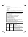
Conformity with UL standards and CSA standards (cUL-listed for Canada)
UL/cUL-listed inverters are subject to the regulations set forth by the UL standards and CSA standards
(cUL-listed for Canada) by installation within precautions listed below.
1. Solid state motor overload protection (motor protection by electronic thermal overload relay) is provided in
each model.
Adjust function codes F10 to F12 to decide the protection level.
2. Suitable for use on a circuit capable of delivering not more than 100,000 rms three-phase symmetrical
amperes, 240 Volts maximum for 208V class input 30HP or less, 230 Volts maximum for 208V class input
40HP or above or 480 Volts maximum for 460V class input.
3. Use 60°C/75°C Cu wire only.
4. Use Class 1 wire only.
5. Field wiring connections must be made by a UL Listed and CSA Certified closed-loop terminal connector
sized for the wire gauge involved. Connector must be fixed using the crimp tool specified by the connector
manufacturer.
6. All circuits with terminals L1/R, L2/S, L3/T, R0, T0, R1, T1 must have a common disconnect and be
connected to the same pole of the disconnect if the terminals are connected to the power supply.
viii
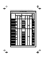
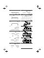
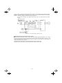
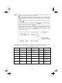
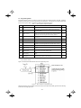
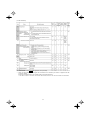
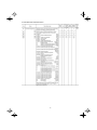
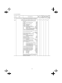
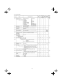
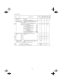
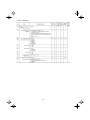
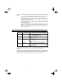
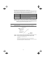
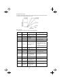
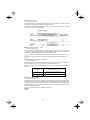
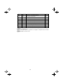
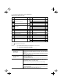
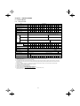
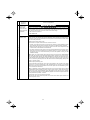
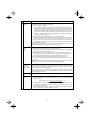
Conformity with UL standards and CSA standards (cUL-listed for Canada) (continued)
Three-phase 208 V
Inverter type
Main
terminal
FRN001F1S-2U
FRN002F1S-2U
FRN003F1S-2U
FRN005F1S-2U
FRN007F1S-2U
FRN010F1S-2U
FRN015F1S-2U
FRN020F1S-2U
FRN025F1S-2U
FRN030F1S-2U
FRN040F1S-2U
FRN050F1S-2U
FRN060F1S-2U
FRN075F1S-2U
FRN100F1S-2U
FRN125F1S-2U
Aux.
Control
Power
Supply
R0, T0
Wire size
AWG (mm2)
Control
circuit
Europe
type
terminal
block
12 (3.3)
8 (8.4)
33.6
(3.8)
119.4
(13.5)
238.9
(27)
424.7
(48)
Control
Aux. Fan circuit
Power
Europe
Supply
type
R1, T1 terminal
block
14
(2.1)
15.9
(1.8)
51.3
(5.8)
Main
terminal
Aux.
Control
Power
Supply
R0, T0
-
4 (21.2)
10.6
(1.2)
4.4
(0.5)
3 (26.7)
2 (33.6)
20
(0.5)
14
(2.1)
1/0 (53.5)
3/0 (85.0)
4/0 (107.2)
300 (152)
2/0x2 (67.4)
4/0x2 (107.2)
14
(2.1)
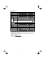
Class J fuse size (A)
Required torque
Ib-in (N·m)
10
15
20
35
60
70
100
125
150
175
200
225
Circuit breaker trip size
(A)
Power supply voltage
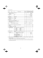
7. Install UL-listed fuses or circuit breaker between the power supply and the inverter, referring to the table
below.
15
20
30
50
70
100
125
150
175
200
225
300 300
350 350
400 400
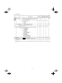
Three-phase 460 V
FRN001F1S-4U
6
FRN002F1S-4U
10 15
15.9
14 (2.1)
FRN003F1S-4U
15
(1.8)
FRN005F1S-4U
20 20
30
FRN007F1S-4U
30
FRN010F1S-4U
40
12 (3.3)
33.6
(3.8)
FRN015F1S-4U
50 40
10 (5.3)
FRN020F1S-4U
70 50
8 (8.4)
51.3
FRN025F1S-4U
80 70
(5.8)
FRN030F1S-4U
80
6 (13.3)
100
100
FRN040F1S-4U
4 (21.2)
FRN050F1S-4U
2 (33.6)
125 125
119.4
FRN060F1S-4U
1 (42.4)
150 150
(13.5)
FRN075F1S-4U
1/0 (53.5)
20
14
10.6
4.4
175 175
(0.5)
(2.1)
(1.2)
(0.5)
3x2 (26.7)
FRN100F1S-4U
FRN125F1S-4U
4/0 (107.2)
200 200
238.9
FRN150F1S-4U
250 (127)
225 225
(27)
2/0x2 (67.4)
300 300
FRN200F1S-4U
FRN250F1S-4U
500 (253)
400 400
FRN300F1S-4U
4/0x2 (107.2)
450 450
14
FRN350F1S-4U
300x2 (152)
500 500
(2.1)
FRN400F1S-4U
350x2 (177)
600 600
FRN450F1S-4U
400x2 (203)
424.7
700 700
(48)
FRN500F1S-4U
300x3 (152)
FRN600F1S-4U
350x3 (177)
1000 1000
FRN700F1S-4U
300x4 (152)
FRN800F1S-4U
350x4 (177)
1200 1200
1600 1600
400x4 (203)
FRN900F1S-4U
*1 Select the rated current of a fuse or a circuit breaker which is suitable to the connecting wire size.
ix
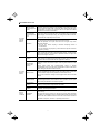
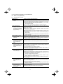
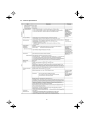
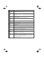
Precautions for use
Driving a 460V
general-purpose
motor
When driving a 460V general-purpose motor with an inverter using
extremely long wires, damage to the insulation of the motor may occur.
Use an output circuit filter (OFL) if necessary after checking with the motor
manufacturer. Fuji motors do not require the use of output circuit filters
because of their reinforced insulation.
Torque
characteristics
and temperature
rise
When the inverter is used to run a general-purpose motor, the temperature
of the motor becomes higher than when it is operated using a commercial
power supply. In the low-speed range, the cooling effect will be weakened,
so decrease the output torque of the motor.
In running
generalpurpose
motors
When an inverter-driven motor is mounted to a machine, resonance may
be caused by the natural frequencies of the machine system.
Vibration
Note that operation of a 2-pole motor at 60 Hz or higher may cause
abnormal vibration.
* The use of a rubber coupling or vibration dampening rubber is
recommended.
* Use the inverter's jump frequency control feature to skip the resonance
frequency zone(s).
Noise
When an inverter is used with a general-purpose motor, the motor noise
level is higher than that with a commercial power supply. To reduce noise,
raise carrier frequency of the inverter. Operation at 60 Hz or higher can
also result in higher noise level.
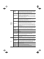
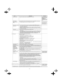
Explosion-proof
motors
When driving an explosion-proof motor with an inverter, use a combination
of a motor and an inverter that has been approved in advance.
Submersible
motors and
pumps
In running
special
motors
Environmental
conditions
Brake motors
These motors have a larger rated current than general-purpose motors.
Select an inverter whose rated output current is greater than that of the
motor.
These motors differ from general-purpose motors in thermal
characteristics. Set a low value in the thermal time constant of the motor
when setting the electronic thermal function.
For motors equipped with parallel-connected brakes, their braking power
must be supplied from the primary circuit. If the brake power is connected
to the inverter's output circuit by mistake, the brake will not work.
Do not use inverters for driving motors equipped with series-connected
brakes.
Geared motors
If the power transmission mechanism uses an oil-lubricated gearbox or
speed changer/reducer, then continuous motor operation at low speed
may cause poor lubrication. Avoid such operation.
Synchronous
motors
It is necessary to take special measures suitable for this motor type.
Contact your Fuji Electric representative for details.
Single-phase
motors
Single-phase motors are not suitable for inverter-driven variable speed
operation. Use three-phase motors.
Use the inverter within the ambient temperature range from -10 to +50°C
(14 to 122°F).
Installation
location
The heat sink of the inverter may become hot under certain operating
conditions, so install the inverter on nonflammable material such as metal.
Ensure that the installation location meets the environmental conditions
specified in Chapter 2, Section 2.1 "Operating Environment."
x
Installing an
MCCB or
RCD/GFCI
Installing an MC
in the secondary
circuit
Installing an MC
in the primary
circuit
Combination with
peripheral
devices
Protecting the
motor
Install a recommended molded case circuit breaker (MCCB) or
residual-current-operated protective device (RCD)/a ground fault circuit
interrupter (GFCI) (with overcurrent protection) in the primary circuit of the
inverter to protect the wiring. Ensure that the circuit breaker rated current is
equivalent to or lower than the recommended rated current.
If a magnetic contactor (MC) is mounted in the inverter's output
(secondary) circuit for switching the motor to commercial power or for any
other purpose, ensure that both the inverter and the motor are completely
stopped before you turn the MC ON or OFF.
Remove the magnet contactor (MC) already installed and built-in surge
suppressor from the inverter's output (secondary) circuit before installing
the MC to switch the motor power.
Do not turn the magnetic contactor (MC) in the primary circuit ON or OFF
more than once an hour as an inverter failure may result.
If frequent starts or stops are required during motor operation, use
(FWD)/(REV) signals or the RUN/STOP key.
The electronic thermal function of the inverter can protect the motor. The
operation level and the motor type (general-purpose motor, inverter motor)
should be set. For high-speed motors or water-cooled motors, set a small
value for the thermal time constant and protect the motor.
If you connect the motor thermal relay to the motor with a long wire, a
high-frequency current may flow into the wiring stray capacitance. This
may cause the relay to trip at a current lower than the set value for the
thermal relay. If this happens, lower the carrier frequency or use the output
circuit filter (OFL).
Use of
power-factor
correcting
capacitor
Do not mount power-factor correcting capacitors in the inverter’s primary
circuit. (Use the DC reactor to improve the inverter power factor.) Do not
use power-factor correcting capacitors in the inverter’s output (secondary)
circuit. An overcurrent trip will occur, disabling motor operation.
Use of surge
suppressor
Do not connect a surge suppressor to the inverter's output (secondary)
circuit.
Reducing noise
Use of a filter and shielded wires is typically recommended to satisfy EMC
Directives.
Measures against
surge currents
If an overvoltage trip occurs while the inverter is stopped or operated under
a light load, it is assumed that the surge current is generated by open/close
of the power-factor correcting capacitor in the power system.
* Connect a DC reactor to the inverter.
Megger test
When checking the insulation resistance of the inverter, use a 500 V
megger and follow the instructions contained in Chapter 7, Section 7.5
"Insulation Test."
Control circuit
wiring length
When using remote control, limit the wiring length between the inverter and
operator box to 67ft (20m) or less and use twisted pair or shielded wire.
Wiring length
between inverter
and motor
If long wiring is used between the inverter and the motor, the inverter will
overheat or trip as a result of overcurrent (high-frequency current flowing
into the stray capacitance) in the wires connected to the phases. Ensure
that the wiring is shorter than 164ft (50m). If this length must be exceeded,
lower the carrier frequency or mount an output circuit filter (OFL).
Wiring size
Select wires with a sufficient capacity by referring to the current value or
recommended wire size.
Wiring type
When several inverters drive motors, do not use one multicore cable in
order to connect several inverters with motors.
Grounding
Securely ground the inverter using the grounding terminal.
Wiring
xi
Selecting
inverter
capacity
Driving
general-purpose
motor
Driving special
motors
Transportation and
storage
Select an inverter according to the applicable motor ratings listed in the
standard specifications table for the inverter.
When high starting torque is required or quick acceleration or deceleration
is required, select an inverter with a capacity one size greater than the
standard.
Select an inverter that meets the following condition:
Inverter rated current > Motor rated current
When transporting or storing inverters, follow the procedures and select locations that meet the
environmental conditions listed in Chapter 1, Section 1.3 "Transportation" and Section 1.4
"Storage Environment."
xii
How this manual is organized
This manual is made up of chapters 1 through 10.
Chapter 1 BEFORE USING THE INVERTER
This chapter describes acceptance inspection and precautions for transportation and storage of the inverter.
Chapter 2 MOUNTING AND WIRING OF THE INVERTER
This chapter provides operating environment, precautions for installing the inverter, wiring instructions for the
motor and inverter.
Chapter 3 OPERATION USING THE KEYPAD
This chapter describes inverter operation using the keypad. The inverter features three operation modes
(Running, Programming and Alarm modes) which enable you to run and stop the motor, monitor running status,
set function code data, display running information required for maintenance, and display alarm data.
Chapter 4 OPERATION
This chapter describes preparation to be made before running the motor for a test and practical operation.
Chapter 5 FUNCTION CODES
This chapter provides a list of the function codes. Function codes to be used often and irregular ones are
described individually.
Chapter 6 TROUBLESHOOTING
This chapter describes troubleshooting procedures to be followed when the inverter malfunctions or detects an
alarm condition. In this chapter, first check whether any alarm code is displayed or not, and then proceed to the
troubleshooting items.
Chapter 7 MAINTENANCE AND INSPECTION
This chapter describes inspection, measurement and insulation test which are required for safe inverter operation.
It also provides information about periodical replacement parts and guarantee of the product.
Chapter 8 SPECIFICATIONS
This chapter lists specifications including output ratings, control system, external dimensions and protective
functions.
Chapter 9 LIST OF PERIPHERAL EQUIPMENT AND OPTIONS
This chapter describes main peripheral equipment and options which can be connected to the FRENIC-Eco
series of inverters.
Chapter 10 CONFORMITY WITH STANDARDS
This chapter describes standards with which the FRENIC-Eco series of inverters comply.
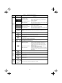
Icons
The following icons are used throughout this manual.
This icon indicates information which, if not heeded, can result in the inverter not operating to full
efficiency, as well as information concerning incorrect operations and settings which can result in
accidents.
This icon indicates information that can prove handy when performing certain settings or operations.
This icon indicates a reference to more detailed information.
xiii
Table of Contents
Preface
........................................................................i
Safety precautions..............................................................i
Precautions for use ...........................................................x
How this manual is organized ............................................ xiii
4.1.1 Inspection and preparation prior to
powering on .................................................. 4-1
4.1.2 Turning ON power and checking................... 4-1
4.1.3 Preparation before running the motor
for a test--Setting function code data ............ 4-1
4.1.4 Test run ......................................................... 4-4
4.2 Operation............................................................... 4-4
Chapter 1 BEFORE USING THE INVERTER ................. 1-1
1.1 Acceptance Inspection........................................... 1-1
1.2 External View and Terminal Blocks........................ 1-2
1.3 Transportation........................................................ 1-4
1.4 Storage Environment ............................................. 1-4
1.4.1 Temporary storage ........................................ 1-4
1.4.2 Long-term storage......................................... 1-4
Chapter 5 FUNCTION CODES ....................................... 5-1
5.1 Function Code Tables ............................................ 5-1
5.2 Overview of Function Codes................................ 5-23
Chapter 6 TROUBLESHOOTING ................................... 6-1
6.1 Before Proceeding with Troubleshooting ............... 6-1
6.2 If No Alarm Code Appears on the LED Monitor...... 6-2
6.2.1 Motor is running abnormally .......................... 6-2
6.2.2 Problems with inverter settings ..................... 6-7
6.3 If an Alarm Code Appears on the LED Monitor ...... 6-8
6.4 If an Abnormal Pattern Appears on the LED
Monitor while No Alarm Code is Displayed .......... 6-19
Chapter 2 MOUNTING AND WIRING OF
THE INVERTER ............................................. 2-1
2.1 Operating Environment.......................................... 2-1
2.2 Installing the Inverter ............................................. 2-1
2.3 Wiring .................................................................... 2-6
2.3.1 Removing and mounting the terminal
block (TB) cover and the front cover ............. 2-6
2.3.2 Removing and mounting the cable guide
plate (for models of 1 to 25HP for 208V and 1 to
30HP for 460V) ........................................... 2-10
2.3.3 Terminal arrangement diagram and screw
specifications .............................................. 2-11
2.3.4 Recommended wire sizes ........................... 2-14
2.3.5 Wiring precautions ...................................... 2-15
2.3.6 Wiring for main circuit terminals and
grounding terminals..................................... 2-15
2.3.7 Wiring for control circuit terminals ............... 2-24
2.3.8 Setting up slide switches and handling
control circuit terminal symbol plate ............ 2-34
2.4 Mounting and Connecting a Keypad.................... 2-35
2.4.1 Mounting style and parts needed
for connection ............................................. 2-35
2.4.2 Mounting/installing steps............................. 2-36
2.5 Cautions Relating to Harmonic Component,
Noise, and Leakage Current................................ 2-38
Chapter 7 MAINTENANCE AND INSPECTION .............. 7-1
7.1 Daily Inspection ..................................................... 7-1
7.2 Periodic Inspection ................................................ 7-1
7.3 List of Periodical Replacement Parts ..................... 7-3
7.3.1 Judgment on service life ............................... 7-3
7.4 Measurement of Electrical Amounts
in Main Circuit ........................................................ 7-5
7.5 Insulation Test........................................................ 7-6
7.6 Inquiries about Product and Guarantee ................. 7-7
Chapter 8 SPECIFICATIONS.......................................... 8-1
8.1 Standard Models.................................................... 8-1
8.1.1 Three-phase 208 V ....................................... 8-1
8.1.2 Three-phase 460 V ....................................... 8-2
8.2 Specifications of Keypad Related .......................... 8-4
8.2.1 General specifications of keypad .................. 8-4
8.2.2 Communications specifications of keypad .... 8-4
8.2.3 Data transmission specifications ................... 8-5
8.3 Common Specifications ......................................... 8-6
8.4 Terminal Specifications .......................................... 8-8
8.4.1 Terminal functions ......................................... 8-8
8.4.2 Running the inverter with keypad .................. 8-9
8.4.3 Running the inverter by terminal
commands .................................................. 8-10
8.5 External Dimensions............................................ 8-12
8.5.1 Standard models ......................................... 8-12
8.5.2 DC reactor................................................... 8-15
8.5.3 Multi-function Keypad.................................. 8-16
8.6 Protective Functions ............................................ 8-17
Chapter 3 OPERATION USING THE MULTI-FUNCTION
KEYPAD......................................................... 3-1
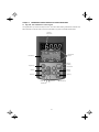
3.1 Key, LED, and LCD Monitors on the Keypad ......... 3-1
3.2 Overview of Operation Modes ............................... 3-4
3.3 Running Mode ....................................................... 3-5
3.3.1 Running/stopping the motor .......................... 3-5
3.3.2 Setting up the frequency and PID process
commands .................................................... 3-8
3.3.3 LED monitor (Monitoring the running status) ...3-12
3.4 Programming Mode ............................................. 3-13
3.4.1 Setting function codes – "1. Data Setting"... 3-14
3.4.2 Setting up function codes quickly using Quick
setup – "0. QUICK SET" ............................. 3-17
3.4.3 Checking changed function codes
–"2. DATA CHECK" ..................................... 3-17
3.4.4 Monitoring the running status
–"3. OPR MNTR" ........................................ 3-18
3.4.5 Checking I/O signal status
– "4. I/O CHECK" ........................................ 3-20
3.4.6 Reading maintenance information
– "5. MAINTENANC"................................... 3-23
3.4.7 Reading alarm information – "6. ALM INF".. 3-26
3.4.8 Viewing cause of alarm
– "7. ALM CAUSE" ...................................... 3-29
3.4.9 Data copying – "8. DATA COPY"................. 3-31
3.4.10 Measuring load factor – "9. LOAD FCTR"... 3-38
3.4.11 Changing function codes covered by Quick setup
– "10. USER SET"....................................... 3-41
3.4.12 Performing communication debugging
– "11. COMM DEBUG"................................ 3-42
3.5 Alarm Mode ......................................................... 3-43
3.6 Other Precautions................................................ 3-45
3.6.1 Function code setting for F02 (Run and
operation).................................................... 3-45
3.6.2 Remote/local operation ............................... 3-45
3.6.3 Tuning motor parameters ............................ 3-46
Chapter 9 LIST OF PERIPHERAL EQUIPMENT AND
OPTIONS ....................................................... 9-1
Chapter 10 CONFORMITY WITH STANDARDS ............ 10-1
10.1 Conformity with UL Standards and Canadian
Standards (cUL-listed for Canada)....................... 10-1
10.1.1 General ....................................................... 10-1
10.1.2 Considerations when using FRENIC-Eco
as a product certified by UL or cUL ............. 10-1
10.2 Conformity with EU Directives ............................. 10-1
10.3 Conformity with Low Voltage Directive................. 10-1
10.3.1 General ....................................................... 10-1
10.3.2 Considerations when using FRENIC-Eco
as a product in conformity with
Low Voltage Directive.................................. 10-1
10.4 Harmonic Component Regulation in the EU ........ 10-2
10.4.1 General ....................................................... 10-2
10.4.2 Conformity with the harmonics regulation ... 10-2
10.5 Conformity with the EMC Directive in the EU....... 10-3
10.5.1 General ....................................................... 10-3
10.5.2 EMC-compliant filter (Option)...................... 10-3
10.5.3 Recommended installation of
EMC-compliant filter.................................... 10-5
10.5.4 EMC-compliant environment and class....... 10-6
Chapter 4 RUNNING THE MOTOR ................................ 4-1
4.1 Running the Motor for a Test.................................. 4-1
xiv
Chapter 1
BEFORE USING THE INVERTER
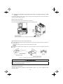
1.1 Acceptance Inspection
Unpack the package and check the following:
(1) An inverter and accessories below are contained in the package.
• Cooling fan fixing screws (for inverters of 7.5 to 30HP for 208V and 10 to 40HP for 460V)
• Keypad fixing screws (for inverters of 1 to 30HP for 208V and 1 to 40HP for 460V)
• Bush rubbers for cable guide plate (for inverters of 1 to 25HP for 208V and 1 to 30HP for 460V)
• Instruction manual (this manual)
(2) The inverter has not been damaged during transportation—there should be no dents or parts missing.
(3) The inverter is the model you ordered. You can check the model name and specifications on the main
nameplate. (Main and sub nameplates are attached to the inverter and are located as shown on the following
page.) For the inverter whose capacity is 40HP for 208V, 50HP for 460V or above, its mass is printed on the
nameplate.
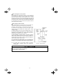
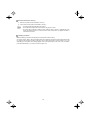
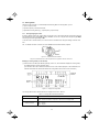
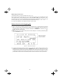
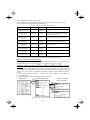
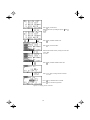
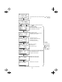
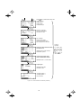
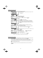
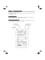
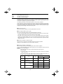
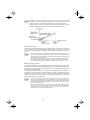
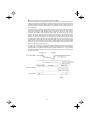
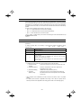
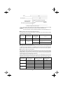
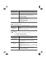
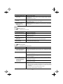
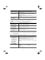
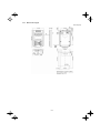
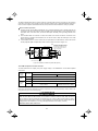
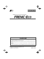
(a) Main Nameplate
(b) Sub Nameplate
Figure 1.1 Nameplates
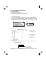
TYPE: Type of inverter
SOURCE:
OUTPUT:
MASS:
SER. No.:
Number of input phases (three-phase: 3PH), input voltage, input frequency, input current
Number of output phases, rated output capacity, rated output voltage, output frequency range, rated
output current, overload capacity
Mass of the inverter in pound
Product number
75A123A0001Z
Serial number of production lot
Production month
1 to 9: January to September
X, Y, or Z: October, November, or December
Production year: Last digit of year
If you suspect the product is not working properly or if you have any questions about your product, contact your
Fuji Electric representative.
1-1
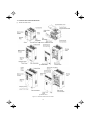
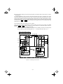
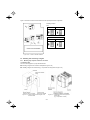
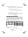
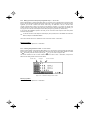
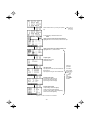
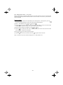
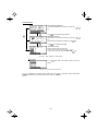
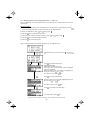
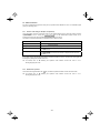
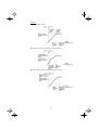
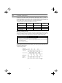
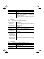
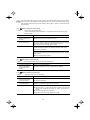
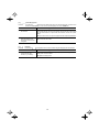
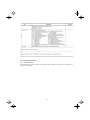
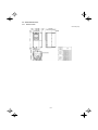
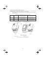
1.2 External View and Terminal Blocks
(1) Outside and inside views
(a) FRN015F1S-2U
(b) FRN040F1S-2U
(c) FRN350F1S-4U
Figure 1.2 Outside and Inside Views of Inverters
1-2
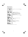
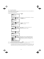
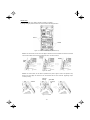
(2) Warning plates and label
Warning Plate
Warning Plate
(a) FRN015F1S-2U
Warning Label
(b) FRN040F1S-2U
Figure 1.3 Warning Plates and Label
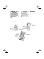
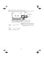
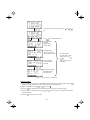
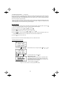
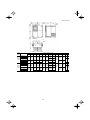
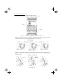
(3) Terminal block location
(a) FRN015F1S-2U
(b) FRN040F1S-2U
(c) FRN350F1S-4U
Figure 1.4 Terminal Blocks and Keypad Enclosure Location
1-3
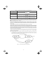
1.3 Transportation
• When carrying an inverter, always support its bottom at the front and rear sides with both hands. Do not hold
covers or individual parts only. You may drop the inverter or break it.
• When hoisting an inverter with hoisting holes, hook or rope the 4 holes evenly.
1.4 Storage Environment
1.4.1
Temporary storage
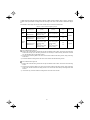
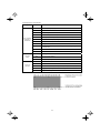
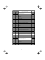
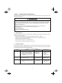
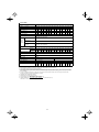
Store the inverter in an environment that satisfies the requirements listed in Table 1.1.
Table 1.1 Environmental Requirements for Storage and Transportation
Item
Requirements
Storage temperature *1
-25 to +70°C(-13° to 158°F)
Relative humidity
5 to 95% *2
Atmosphere
The inverter must not be exposed to dust, direct sunlight, corrosive or flammable gases, oil
mist, vapor, water drops or vibration. The atmosphere must contain only a low level of salt.
(0.01 mg/cm2 or less per year)
Atmospheric pressure
86 to 106 kPa (in storage)
A location where the inverter is not subject to abrupt
changes in temperature that would result in the formation of
condensation or ice.
70 to 106 kPa (during transportation)
*1 Assuming a comparatively short storage period (e.g., during transportation or the like).
*2 Even if the humidity is within the specified requirements, avoid such places where the inverter will be subjected to
sudden changes in temperature that will cause condensation to form.
Precautions for temporary storage
(1) Do not leave the inverter directly on the floor.
(2) If the environment does not satisfy the specified requirements, wrap the inverter in an airtight vinyl sheet or
the like for storage.
(3) If the inverter is to be stored in an environment with a high level of humidity, put a drying agent (such as silica
gel) in the airtight package described in item (2).
1.4.2
Long-term storage
The long-term storage methods for the inverter vary largely according to the environment of the storage site.
General storage methods are described below.
(1) The storage site must satisfy the requirements specified for temporary storage.
However, for storage exceeding three months, the ambient temperature should be within the range from -10
to +30 °C(14 to 56°F). This is to prevent the electrolytic capacitors in the inverter from deteriorating.
(2) The inverter must be stored in a package that is airtight to protect it from moisture. Include a drying agent
inside the package to maintain the relative humidity inside the package to within 70%.
(3) If the inverter has been installed in the equipment or control board at a construction site where it may be
subjected to humidity, dust or dirt, then remove the inverter and store it in a suitable environment specified in
Table 1.1.
Precautions for storage over 1 year
If the inverter will not be powered on for a long time, the property of the electrolytic capacitors may deteriorate.
Power the inverters on once a year and keep them on for 30 to 60 minutes. Do not connect the inverters to motors
or run the motor.
1-4
Chapter 2
MOUNTING AND WIRING OF THE INVERTER
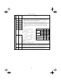
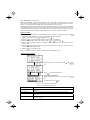
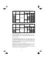
2.1 Operating Environment
Install the inverter in an environment that satisfies the requirements listed in Table 2.1.
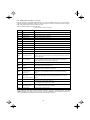
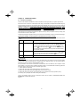
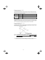
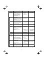
Table 2.1 Environmental Requirements
Item
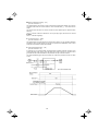
Table 2.2 Output Current Derating Factor in
Relation to Altitude
Specifications
Site location
Indoors
Ambient
temperature
-10 to +50°C(14 to 122°F) (Note 1)
Relative
humidity
5 to 95% (No condensation)
Atmosphere
The inverter must not be exposed to dust, direct
sunlight, corrosive gases, flammable gas, oil mist,
vapor or water drops.
Pollution degree 2 (IEC60664-1) (Note 2)
Altitude
The atmosphere can contain a small amount of salt.
(0.01 mg/cm2 or less per year)
The inverter must not be subjected to sudden
changes in temperature that will cause
condensation to form.
Altitude
3300ft(1000m) max. (Note 3)
Atmospheric
pressure
86 to 106 kPa
Vibration
For inverters of 100 HP or below
3 mm (Max. amplitude)
2 to less than 9 Hz
9.8 m/s2
9 to less than 20 Hz
2 m/s2
20 to less than 55 Hz
1 m/s
2
55 to less than 200 Hz
For inverters of 125 HP or above
3 m/s2 (Max. amplitude)
2 to less than 9 Hz
2 m/s2
1 m/s2
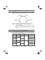
Output
current
derating
factor
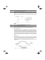
3300ft(1000m) or lower
1.00
3300ft(1000m) to 4900ft(1500m)
0.97
4900ft(1500m) to 6600ft(2000m)
0.95
6600ft(2000m) to 8200ft(2500m)
0.91
8200ft(2500m) to 9800ft(3000m)
0.88
(Note 1) When inverters are mounted
side-by-side without any gap between them
(5HP for 208V, 7.5HP for 460HP or below),
the ambient temperature should be within
the range from -10 to +40°C(14 to 104°F).
(Note 2) Do not install the inverter in an
environment where it may be exposed to
cotton waste or moist dust or dirt which will
clog the heat sink in the inverter. If the
inverter is to be used in such an
environment, install it in the enclosure of
your system or other dustproof containers.
(Note 3) If you use the inverter in an
altitude above 3300ft(1000m), you should
apply an output current derating factor as
listed in Table 2.2.
9 to less than 55 Hz
55 to less than 200 Hz
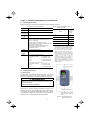
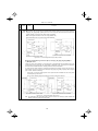
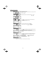
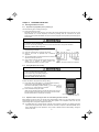
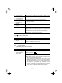
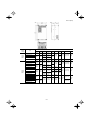
2.2 Installing the Inverter
(1) Mounting base
The temperature of the heat sink will rise up to approx. 90°C during
operation of the inverter, so the inverter should be mounted on a
base made of material that can withstand temperatures of this level.
Install the inverter on a base constructed from metal or other
non-flammable material.
A fire may result with other material.
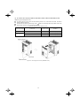
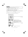
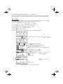
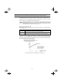
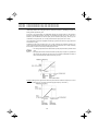
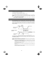
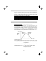
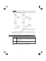
(2) Clearances
Ensure that the minimum clearances indicated in Figure 2.1 are
maintained at all times. When installing the inverter in the enclosure
of your system, take extra care with ventilation inside the enclosure
as the temperature around the inverter will tend to increase. Do not
install the inverter in a small enclosure with poor ventilation.
* 2.0inch(50mm) for models
of 460 V series 125HP or
above
Figure 2.1 Mounting Direction and
Required Clearances
2-1
When mounting two or more inverters
Horizontal layout is recommended when two or more inverters are
to be installed in the same unit or enclosure. If it is necessary to
mount the inverters vertically, install a partition plate or the like
between the inverters so that any heat radiating from an inverter will
not affect the one/s above. As long as the ambient temperature is
40°C(104°F)or lower, inverters can be mounted side-by-side without
any gap between them (only for inverters with a capacity of 5HP for
208V, 7.5HP for 460V or below).
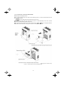
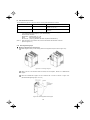
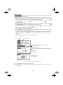
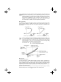
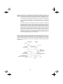
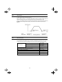
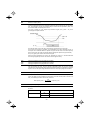
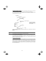
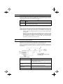
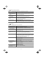
When employing external cooling
At the shipment time, the inverter is set up for mount inside your
equipment or enclosure so that cooling is done all internally.
To improve cooling efficiently, you can take the heat sink out of
the equipment or the enclosure (as shown on the right) so that
cooling is done both internally and externally (this is called
"external cooling").
In external cooling, the heat sink, which dissipates about 70% of
the total heat (total loss) generated into air, is situated outside the
equipment or the enclosure. As a result, much less heat is
radiated inside the equipment or the enclosure.
To take advantage of external cooling, you need to use the
external cooling attachment option for inverters with a capacity of
30HP for 208V, 40HP for 460V or below, or simply re-position the
mounting bases for the cooling unit for inverters with a capacity of
40HP for 208V, 50HP for 460V or above.
In an environment with high humidity or a lot of fibrous dust,
however, do not use external cooling in an environment with high
humidity or a lot of fibrous dust, which tends to clog the heat sink.
For details, refer to the Mounting Adapter for External
Cooling "PB-F1" Installation Manual and FRENIC-Eco
User’s Manual.
Figure 2.2
External Cooling
Prevent lint, paper fibers, sawdust, dust, metallic chips, or other foreign materials from getting into the
inverter or from accumulating on the heat sink.
This may result in a fire or accident.
2-2
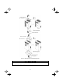
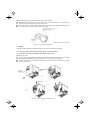
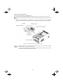
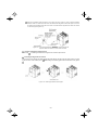
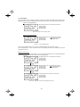
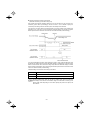
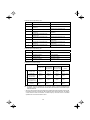
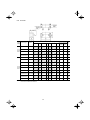
To utilize external cooling for inverters with a capacity of 40HP for 208V, 50HP for 460V or above, change the
position of the top and bottom mounting bases from the edge to the center of the inverter as illustrated in Figure
2.3.
Screws differ in size, length and count for each inverter. Be sure to refer to the table below.
Table 2.3 Screw Count and Tightening Torque
Power
supply
voltage
3-phase
208 V
Base fixing screw
(Count)
Case fixing screw
(Count)
Tightening torque
(N•m)
FRN040F1S-2U to
FRN100F1S-2U
M6 × 20
(3 pcs each for upper
and lower sides)
M6 × 12
(3 pcs for upper side)
5.8
FRN050F1S-4U to
FRN150F1S-4U
M6 × 20
(3 pcs each for upper
and lower sides)
M6 × 12
(3 pcs for upper side)
M6 × 20
(2 pcs each for upper
and lower sides)
M6 × 20
(2 pcs each for upper
and lower sides)
M5 × 16
(4 pcs each for upper
and lower sides)
M5 × 12
(4 pcs each for upper
and lower sides)
Inverter type
3-phase
460 V
FRN200F1S-4U to
FRN350F1S-4U
Refer to:
Figure A
5.8
5.8
Figure B
3.5
For models shown in Figure A
1) Remove all of the base fixing screws from the top and bottom of the inverter. Also remove the case fixing
screws from the top. (The case fixing screws are not necessary in external cooling. Store them for future
use. On the bottom are no case fixing screws.)
2) Secure the top mounting base to the center of the inverter with the base fixing screws, using case fixing
screw holes.
3) Secure the bottom mounting base to the center of the inverter with the base fixing screws.
For models shown in Figure B
1) Remove all of the base fixing screws from the top and bottom of the inverter. Also remove the case fixing
screws.
2) Secure the top mounting base to the center of the inverter with the base fixing screws, using case fixing
screw holes. Set the removed case fixing screws to the screw holes where the top mounting bases were
secured.
3) In the same way, secure the bottom mounting base to the center of the inverter.
2-3
Figure A
Figure B
Figure 2.3 Relocating the Top and Bottom Mounting Bases
When moving the top and bottom mounting bases, use only the specified screws.
A fire or an accident may be caused.
2-4
(3) Mounting direction
Mount the inverter vertically to the mounting surface and fix it securely with four screws or bolts so that the logo
"FRENIC-Eco" can be seen from the front.
Do not mount the inverter upside down or horizontally. Doing so will reduce the heat dissipation
efficiency of the inverter and cause the overheat protection function to operate, so the inverter will not
run.
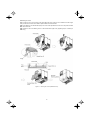
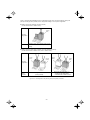
(4) Solving abnormal vibration after installation
If any vibration in the surroundings reaches the inverter and causes abnormal vibration to the cooling fan(s) or
the keypad, fix them firmly using the fixing screws provided as accessories.
Fixing the cooling fan(s)
Table 2.4
Power
supply
voltage
Threephase
208 V
Threephase
460 V
Nominal
applied motor
(HP)
Fixing Screws
Inverter type
7
FRN007F1S-2U
10
FRN010F1S-2U
15
FRN015F1S-2U
20
FRN020F1S-2U
25
FRN025F1S-2U
30
FRN030F1S-2U
10
FRN010F1S-4U
15
FRN015F1S-4U
20
FRN020F1S-4U
25
FRN025F1S-4U
30
FRN030F1S-4U
40
FRN040F1S-4U
Screw size
(accessory)
Tightening
torque
(N·m)
Refer to:
M4x35 (4 pcs)
0.8
Figure A
M4x50 (2 pcs)
0.5
Figure B
M4x35 (4 pcs)
0.8
Figure A
M4x50 (2 pcs)
0.5
Figure B
Figure A
Figure B
Figure 2.4 Fixing the Cooling Fan(s)
2-5
Fixing the keypad (for models of 30HP for 208V, 40HP for 460V or below)
Remove the terminal block (TB) cover and the front cover. (For the procedure, refer to 2.3.1 “Removing and
mounting the terminal block (TB) cover and the front cover.”)
To fix the front cover and keypad, hold the front cover and the keypad together and tighten the two attached
screws (provided as accessories) from the back of the keypad.
Tightening torque: 6.2lb-in(0.7 N·m)
Figure 2.5
Fixing Multi-function Keypad
2.3 Wiring
Follow the procedure below. (In the following description, the inverter has already been installed.)
2.3.1
Removing and mounting the terminal block (TB) cover and the front cover
(1) For inverters with a capacity of 30HP for 208V, 40HP for 460V or below
Removing the covers
To remove the terminal block (TB) cover, first loosen the TB cover fastening screw on it, and put your finger
in the dimple of the terminal block (TB) cover (labeled “PULL”), and then pull it up toward you.
To remove the front cover, hold it with both hands, slide it downward to unlatch. Tilt the front cover toward
you, and pull it upward.
Figure 2.6
Removing the Covers (FRN015F1S-2U)*
2-6
Mounting the covers
Put the front cover to the inverter case while fitting the edge of the front cover between the both hinges
provided on the inverter case. Slide it upward until the front cover latches.
Fit the latches on the terminal block (TB) cover in the holes provided to the front cover and push it towards
the inverter case.
Tighten the TB cover fastening screw on the terminal block (TB) cover (Tightening torque: 15.9lb-in(1.8
N·m)).
Figure 2.7
Mounting the Covers (FRN015F1S-2U)*
2-7
(2) For inverters with a capacity of 40HP for 208V, 50HP for 460V to 125HP for 208V, 200HP for 460V
Removing and mounting the covers
To remove the front cover, loosen the four fastening screws on it, hold it with both hands, and slide it
upward. (Refer to Figure 2.8.)
Put the front cover back in reverse order of the . Make sure to properly match the position of the screw
holes on both of the front cover and inverter case.
Table 2.5 Screw count and tightening torque
Power supply voltage
Three-phase 208 V
Three-phase 460 V
Inverter type
Front cover screw
Tightening torque
lb-in(N·m)
FRN040F1S-2U
to FRN100F1S-2U
M4x8 (4 pcs)
15.9(1.8)
FRN050F1S-4U
to FRN150F1S-4U
M4x8 (4 pcs)
15.9(1.8)
M4x8 (4 pcs)
31.0(3.5)
FRN200F1S-4U
Figure 2.8 Removing the Front Cover (FRN040F1S-2U)*
2-8
(3) For inverters with a capacity of 250HP to 300HP
Removing and mounting the covers
To remove the lower front cover, loosen the five fastening screws on it, and hold it with both hands, and
then slide it upward.
You can do wiring works just removing the lower front cover.
To remove the upper front cover, loosen the five screws on it while supporting it with a hand. Pull and
remove it with both hands. (Refer to Figure 2.9.)
Put back the upper and lower front covers in reverse order of
and . Make sure to properly match the
position of the screw holes on the upper and lower front covers and inverter case.
Tightening torque: 31.0lb-in(3.5 N·m)
Figure 2.9 Removing the Front Covers (FRN350F1S-4U)*
2-9
2.3.2
Removing and mounting the cable guide plate (for models of 1 to 25HP for 208V and 1 to 30HP
for 460V)
For inverters of 25HP for 208V, 30HP for 460V or below use the cable guide plate to secure IP20 protective
structure. Follow the steps to work on it.
Removing the cable guide plate
Before to proceed, remove the terminal block cover in advance.
Remove the cable guide plate fastening screw, and pull the cable guide plate.
Figure 2.10 Removing the Cable Guide Plate (FRN015F1S-2U)*
Opening half-punched holes and mounting rubber bushes
Tap the three half-punched holes of the cable guide plate by using a screwdriver grip end or the like and
punch them out.
Be careful not to injure yourself by sharp cutting edges of parts.
Set the three attached rubber bushes in the punched holes. Make cut-outs on the rubber bushes before
wiring.
Figure 2.11 Punching out the Holes and Mounting the Rubber Bushes
Be sure to use the rubber bushes. If not, a sharp cutting edge of the cable guide plate hole may damage the cable
sheath. This may induce a short-circuit fault or ground fault.
A fire or an accident may be caused.
Mounting the cable guide plate
Mount the cable guide plate following the steps illustrated in Figure 2.10 in reverse. (Tightening torque:
15.9lb-in(1.8 N•m))
2-10
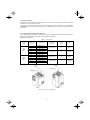
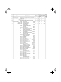
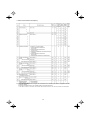
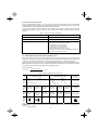
2.3.3
Terminal arrangement diagram and screw specifications
The table below shows the main circuit screw sizes, tightening torque and terminal arrangements. Note that the
terminal arrangements differ according to the inverter types. Two terminals designed for grounding shown as the
symbol,
in Figures A to J make no distinction between a power supply source (a primary circuit) and a motor
(a secondary circuit).
(1) Arrangement of the main circuit terminals
Table 2.6
Power supply Nominal applied
voltage
motor(HP)
Threephase
208 V
Threephase
460 V
Main Circuit Terminal Properties
Inverter type
Terminal
screw size
Tightening
torque(N·m)
Grounding
screw size
Tightening
torque(N·m)
Refer to:
M4
1.8
M4
1.8
Figure A
M5
3.8
M5
3.8
M6
5.8
M6
5.8
M8
13.5
1
FRN001F1S-2U
2
FRN002F1S-2U
3
FRN003F1S-2U
5
7
10
15
20
25
FRN005F1S-2U
FRN007F1S-2U
FRN010F1S-2U
FRN015F1S-2U
FRN020F1S-2U
FRN025F1S-2U
30
FRN030F1S-2U
40
FRN040F1S-2U
50
60
75
100
FRN050F1S-2U
FRN060F1S-2U
FRN075F1S-2U
FRN100F1S-2U
M10
27
125
FRN125F1S-2U
M12
48
M10
27
Figure J
1
2
3
5
7
10
15
20
25
30
FRN001F1S-4U
FRN002F1S-4U
FRN003F1S-4U
FRN005F1S-4U
FRN007F1S-4U
FRN010F1S-4U
FRN015F1S-4U
FRN020F1S-4U
FRN025F1S-4U
FRN030F1S-4U
M4
1.8
M4
1.8
Figure A
M5
3.8
M5
3.8
M6
5.8
M6
5.8
40
FRN040F1S-4U
50
60
75
100
125
150
FRN050F1S-4U
FRN060F1S-4U
FRN075F1S-4U
FRN100F1S-4U
FRN125F1S-4U
FRN150F1S-4U
200
FRN200F1S-4U
250
FRN250F1S-4U
300
350
400
450
500
600
700
800
900
FRN300F1S-4U
FRN350F1S-4U
FRN400F1S-4U
FRN450F1S-4U
FRN500F1S-4U
FRN600F1S-4U
FRN700F1S-4U
FRN800F1S-4U
FRN900F1S-4U
Figure B
Figure C
Figure D
Figure E
M8
13.5
Figure G
Figure B
Figure C
Figure D
M8
Figure E
13.5
M8
M10
13.5
Figure F
Figure G
27
Figure H
Figure I
M12
48
M10
27
Figure K
Figure L
Figure M
Terminal R0, T0 (Common to all types): Screw size M3.5, Tightening torque 10.6lb-in(1.2 (N·m))
Terminal R1, T1: Screw size M3.5, Tightening torque 8lb-in(0.9 (N·m)) (for the models of 208 V series 50HP or above, for
460 V series 60HP or above
2-11
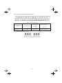
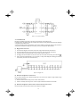
Charing
Lamp
Figure J
R0 T0
R1
T1
V
U
L2/S
L1/R
G
L3/T
W
P(+)
P1
N(-)
G
Charing
Lamp
Figure K
R0 T0
R1
L2/S
L1/R
T1
L3/T
V
U
P(+)
P1
W
N(-)
G
G
Charing
Lamp
Figure L
R0 T0
R1
L2/S
L1/R
L2/S
L1/R
T1
L3/T
L3/T
G
V
U
W
V
U
P1
W
P(+)
N(-)
G
Figure M
Charing
Lamp
R0 T0
R1
L1/R
L2/S
L1/R
G
2-12
L2/S
T1
L3/T
L3/T
P1
P(+)
V
U
P1
V
U
N(-)
W
W
G
(2) The control circuit terminals (common to all models)
Screw size: M3
Tightening torque: 4.4 to 5.3lb-in(0.5 to 0.6 (N·m))
Table 2.7
Screwdriver to be used
(Head style)
Flat head
(0.6 x 3.5 mm)
Control Circuit Terminals
Bared wire length
Dimension of openings in the
control circuit terminals
Allowable wire size
AWG26 to AWG16
(0.14 to 1.5 mm2)
0.28 inch (7 mm)
0.10 (W) x 0.11 (H) inch
(2.75 (W) x 2.86 (H) mm)
(3) The RS-485 communication terminals
Screw size: M3
Tightening torque: 4.4 lb-in(0.5 (N·m))
2-13
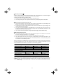
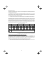
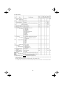
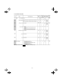
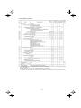
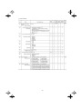
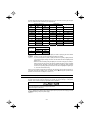
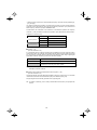
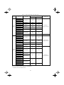
2.3.4
Recommended wire sizes
Table 2.8 lists the recommended wire sizes. Those for main circuits are examples for using a single wire (for
60/75°C(140/167°F)) at an ambient temperature of 50°C(122°F).
Table 2.8
Recommended Wire Sizes
Three-phase 460 V
Three-phase 208 V
Nominal
applied
motor
(HP)
1
2
3
5
7
10
15
20
25
30
40
50
60
75
100
125
1
2
3
5
7
10
15
20
25
30
40
50
60
75
100
125
150
200
250
300
350
400
450
500
600
700
800
900
Main circuits
Inverter type
FRN001F1S-2U
FRN002F1S-2U
FRN003F1S-2U
FRN005F1S-2U
FRN007F1S-2U
FRN010F1S-2U
FRN015F1S-2U
FRN020F1S-2U
FRN025F1S-2U
FRN030F1S-2U
FRN040F1S-2U
FRN050F1S-2U
FRN060F1S-2U
FRN075F1S-2U
FRN100F1S-2U
FRN125F1S-2U
FRN001F1S-4U
FRN002F1S-4U
FRN003F1S-4U
FRN005F1S-4U
FRN007F1S-4U
FRN010F1S-4U
FRN015F1S-4U
FRN020F1S-4U
FRN025F1S-4U
FRN030F1S-4U
FRN040F1S-4U
FRN050F1S-4U
FRN060F1S-4U
FRN075F1S-4U
FRN100F1S-4U
FRN125F1S-4U
FRN150F1S-4U
FRN200F1S-4U
FRN250F1S-4U
FRN300F1S-4U
FRN350F1S-4U
FRN400F1S-4U
FRN450F1S-4U
FRN500F1S-4U
FRN600F1S-4U
FRN700F1S-4U
FRN800F1S-4U
FRN900F1S-4U
Auxiliary
Main circuit power
Inverter
Power
input
Grounding
output
Input
(L1/R, L2/S, L3/T)
[ G]
[U, V, W] (Ctrl. cct.)
w/ DCR w/o DCR
[R0, T0]
2
3.5
5.5
14
22
38
60
100
2
2
2
3.5
5.5
5.5
3.5
14
8
22
14
60
100
22
38
2
3.5
5.5
8
14
22
14
5.5
8
22
60
60
100
2
150
100
150
200
2
3.5
3.5
5.5
5.5
14
14
38
22
2
38
60
100
100
38
200
250
325
200x2
250
60
0.75
to
1.25
150
150
150
325
200x2
250x2
0.75
to
1.25
38
60
-
3.5
5.5
8
14
22
22
22
14
60
100
200
2
3.5
22
38
38
-
2
5.5
8
2
2
2
3.5
DCR
[P1, P (+)]
[R1, T1]
38
-
150
(Fans)
8
14
38
Auxiliary
Power
Input
Control circuit
Power supply
voltage
Recommended wire size (mm2 ) *1
2
200
250
325
200x2
250x2
325x2
325x2
150x3
325x2
100
150x3
200x3
DCR: DC reactor
*1 Use crimp style terminals that are insulated or insulate using tubing or other methods acceptable by local and national
codes. The insulation thermal rating of the wiring must be 60 or 75°C(140 or 167°F) with the inverter ambient
temperature of 50°C(122°F).
2-14
250x2
2.3.5
Wiring precautions
Follow the rules below when performing wiring for the inverter.
(1) Make sure that the source voltage is within the rated voltage range specified on the nameplate.
(2) Be sure to connect the three-phase power wires to the main circuit power input terminals L1/R, L2/S and
L3/T of the inverter. If the power wires are connected to other terminals, the inverter will be damaged when
the power is turned on.
(3) Always connect the grounding terminal to prevent electric shock, fire or other disasters and to reduce
electric noise.
(4) Use crimp terminals covered with insulated sleeves for the main circuit terminal wiring to ensure a reliable
connection.
(5) Keep the power supply wiring (primary circuit) and motor wiring (secondary circuit) of the main circuit, and
control circuit wiring as far away as possible from each other.
•
•
•
When wiring the inverter to the power source, insert a recommended molded case circuit breaker
(MCCB) or a ground fault circuit interrupter (GFCI) (with overcurrent protection) in the path of each
pair of power lines to inverters. Use the devices recommended ones within the related current range.
Use wires in the specified size.
Tighten terminals with specified torque.
Otherwise, fire could occur.
•
•
Do not connect a surge suppressor to the inverter's output circuit.
Do not use one multicore cable in order to connect several inverters with motors.
Doing so could cause fire.
•
Ground the inverter in compliance with the national or local electric code.
Otherwise, electric shock or fire could occur.
•
•
Qualified electricians should carry out wiring.
Be sure to perform wiring after turning the power off.
Otherwise, electric shock could occur.
•
Be sure to perform wiring after installing the inverter.
Otherwise, electric shock or injuries could occur.
•
Ensure that the number of input phases and the rated voltage of the product match the number of
phases and the voltage of the AC power supply to which the product is to be connected.
Do not connect the power source wires to output terminals (U, V, and W).
Doing so could cause fire or an accident.
•
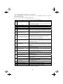
2.3.6
Wiring for main circuit terminals and grounding terminals
Table 2.9 shows the main circuit power terminals and grounding terminals.
Table 2.9 Symbols, Names and Functions of the Main Circuit Power Terminals
Symbol
Name
Functions
L1/R, L2/S, L3/T
Main circuit power
inputs
Connect the 3-phase input power lines.
U, V, W
Inverter outputs
Connect a 3-phase motor.
R0, T0
Auxiliary power input for
the control circuit
For a backup of the control circuit power supply, connect AC
power lines same as that of the main power input.
P1, P(+)
DC reactor connection
Connect a DC reactor (DCR) for improving power factor (an
option for the inverter whose capacity is 60HP for 208V, 75HP for
460V or below).
P(+), N(-)
DC link bus
Connect a DC link bus of other inverter(s). An optional
regenerative converter is also connectable to these terminals.
R1, T1
Auxiliary power input for
the fans
Normally, no need to use these terminals. Use these terminals for
an auxiliary power input of the fans in a power system using a
power regenerative PWM converter (RHC series).
Grounding for inverter
and motor
Grounding terminals for the inverter’s chassis (or case) and
motor. Earth one of the terminals and connect the grounding
terminal of the motor. Inverters provide a pair of grounding
terminals that function equivalently.
G
2-15
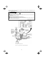
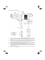
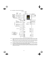
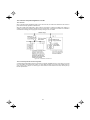
Follow the procedure below for wiring and configuration of the inverter. Figure 2.12 illustrates the wiring
procedure with peripheral equipment.
Wiring procedure
Grounding terminals ( G)
Inverter output terminals (U, V, W, and
G)
DC reactor connection terminals (P1 and P(+))*
Switching connectors* (For the models of 208 V 50HP or above, for 460 V 75HP or above. Refer to
page 2-18.)
DC link bus terminals (P(+) and N(-))*
Main circuit power input terminals (L1/R, L2/S and L3/T)
Auxiliary power input terminals for the control circuit (R0 and T0)*
Auxiliary power input terminals for the fans (R1 and T1)* (For models of 208 V 50HP or above, for 460
V 75HP or above. Refer to page 2-22.)
* Perform wiring as necessary
Figure 2.12 Wiring Procedure for Peripheral Equipment
2-16
Grounding terminals ( G)
Be sure to ground either of the two grounding terminals for safety and noise reduction. The inverter is designed
to use with a safety grounding to avoid electric shock, fire and other disasters.
Grounding terminals should be grounded as follows:
1) Ground the inverter in compliance with the national or local electric code.
2) Use a thick grounding wire with a large surface area and keep the wiring length as short as possible.
Main circuit power terminals (L1/R, L2/S, L3/T)
1) Connect these terminals to the power supply via a molded-case circuit breaker or ground-leakage circuit
breaker for circuit protection. Phase-sequence matching is unnecessary.
2) To insure safety, a magnetic contactor should be used to disconnect the drive from the power supply when
the drive protective function activates.
3) Use control circuit terminal FWD/REV or the RUN/STOP key on the keypad panel to start or stop the drive.
The main circuit power should be used to start or stop the drive only if absolutely necessary and then
should not be used more than once every hour.
4) If you need to connect these terminals to a single-phase power supply, please contact the factory.
Drive output terminals (U, V, W)
1) Connect these terminals to a 3-phase motor in the correct phase sequence. If the direction of motor rotation
is incorrect, exchange any two of the U, V, and W phases.
2) Do not connect a power factor correction capacitor or surge absorber to the drive output.
3) If the cable from the drive to the motor is very long, a high-frequency current may be generated by stray
capacitance between the cables and result in an overcurrent trip of the drive, an increase in leakage current,
or a reduction in current indication precision.
When a motor is driven by a PWM-type drive, the motor terminals may be subject to surge voltage generated by
drive element switching. If the motor cable (with 460V series motors, in particular) is particularly long, surge
voltage will deteriorate motor insulation. To prevent this, use the following guidelines:
Drives 7.5 HP and larger
Motor Insulation Level
1000V
1300V
1600V
460 VAC Input Voltage
66 ft (20 m)
328 ft (100 m)
1312 ft (400 m) *
208 VAC Input Voltage
1312 ft (400 m) *
1312 ft (400 m) *
1312 ft (400 m) *
Motor Insulation Level
1000V
1300V
1600V
460 VAC Input Voltage
66 ft (20 m)
165 ft (50 m) *
165 ft (50 m) *
208 VAC Input Voltage
328 ft (100 m) *
328 ft (100 m) *
328 ft (100 m) *
Drives 5 HP and smaller
* For this case the cable length is determined by secondary effects and not voltage spiking.
When a motor protective thermal O/L relay is inserted between the drive and the motor, the thermal
O/L relay may malfunction (particularly in the 460V series), even when the cable length is 165 feet
(50m) or less. To correct, insert a filter or reduce the carrier frequency. (Use function code “F26
Motor sound”.)
2-17
DC reactor terminals, P1 and P (+)
1)
Remove the jumper bar from terminals P1 and P(+).
2)
Connect a DC reactor (option) to terminals P1 and P(+).
• The wiring length should be 33ft(10 m) or below.
• Do not remove the jumper bar if a DC reactor is not going to be used.
• An inverter with a capacity of 75HP for 208V, 100HP for 460V or above is equipped with a DC
reactor as standard. Be sure to connect the DC reactor except when an optional converter is
connected to the inverter.
Switching connectors
Power switching connectors (CN UX) (for the models of 460 V 75HP or above)
An inverter of 460 V 75HP or above is equipped with a set of switching connectors CU UX (male) which should
be configured with a jumper according to the power source voltage and frequency. Set the jumper to U1 or U2
depending upon the power source voltage applied to the main power inputs (L1/R, L2/S, L3/T) or auxiliary
power input terminals (R1, T1) for fans, as shown in Figure 2.16.
2-18
Fan power supply switching connectors (CN R) and (CN W) (for models of 50HP or above (208 V) or 75HP or
above (460 V))
The standard FRENIC-Eco series of inverters also accept DC-linked power input in combination with a power
regenerative PWM converter (RHC series). Even when you drive the inverter with a DC-linked power, however,
you also need to supply AC power for models of 50HP or above (208 V) or 75HP or above (460 V), since it
contains components such as AC fans that are driven by AC power. In this case, reinstall the connectors (CN R)
and (CN W) to the NC and FAN positions respectively and supply the power to the auxiliary power input
terminals (R1, T1).
For the actual procedure, refer to Figures 2.14 to 2.16 below.
On the fan power supply switching connectors (CN R) and (CN W), the jumpers are installed
at FAN and NC positions respectively by factory default. Do not relocate the jumper unless you
drive the inverter with a DC-linked power supply.
If there is a mistake in the installation of the jumpers for the switching connectors, the cooling fan will
not run, causing a heat sink overheating alarm "0h1 " or a charger circuit error alarm "pbf ."
208 V series 50 HP or above
460 V series 75 HP or above
Inverter Unit
P1 P(+) N(-)
L1/R
C
L2/S
U
+
V
L3/T
W
R1
T1
R1
CN R
L3/T
L1/R
T1
CN W
CN R
CN W
FAN
NC
Power circuit
PCB
FAN
NC
Power c ircuit
PCB
Standard configuration
- DC-linked power input configuration
- PWM converter linked conf iguration
Figure 2.13
Switching Fan Power Source
2-19
Setting up the jumpers for the connectors (CN UX), (CN R) and (CN W)
These switching connectors are located on the power printed circuit board (power PCB) mounted at the right
hand side of the control printed circuit board (control PCB) as shown below.
Switching Connectors for
Power Input
(CN UX)
Switching Connectors for
Fans (CN R), (CN W)
U2 U1
FAN
NC
Auxiliary Power Input Terminals for Control Circuit
Figure 2.14 Location of Switching Connectors and Auxiliary Power Input Terminals
To remove the jumper, pinch its upper side
between your fingers, unlock its fastener and
pull it up. To insert it, pull it down as firmly as it
locks with the connector until you will have
heard a click sound.
Figure 2.15 Inserting/Removing the Jumpers
2-20
Figure 2.16 shown below illustrates how the configuration jumpers of the connectors (CN UX), (CN R) and
(CN W) are setup by factory defaults, and to change their settings for a new power configuration.
Setting up the power switching connector (CN UX)
(for the models of 460 V 75HP or above)
(CN UX)
(Red)
Connector
configuration
Note
Allowable power input voltage range should
be within – 15% to +10% of power source
voltage.
Setting up the fan power supply switching connectors (CN R) and (CN W)
(for the models of 208 V 50HP or above ; 460 V 75HP or above)
(CN R)
(Red)
(CN W)
(White)
(CN W)
(White)
(CN R)
(Red)
Connector
configuration
Power
system
operation
When using no terminal R1, T1
(Factory default)
When using the terminals R1, T1
• Feeding the DC-linked power
• Combined with a PWM converter
Figure 2.16 Reconfiguration of the (CN UX), (CN R) and (CN W) Connectors
2-21
DC link bus terminals, P (+) and N (-)
These are provided for the DC link bus powered system. Connect these terminals with terminals P(+) and N (-)
of other inverters.
Consult your Fuji Electric representative if these terminals are to be used.
Main circuit power input terminals, L1/R, L2/S, and L3/T (three-phase input)
1) For safety, make sure that the molded case circuit breaker (MCCB) or magnetic contactor (MC) is turned off
before wiring the main circuit power input terminals.
2) Connect the main circuit power supply wires (L1/R, L2/S and L3/T) to the input terminals of the inverter via
an MCCB or residual-current-operated protective device (RCD)/a ground fault circuit interrupter (GFCI)*,
and MC if necessary.
It is not necessary to align phases of the power supply wires and the input terminals of the inverter with
each other.
* With overcurrent protection
It is recommended that a magnetic contactor be inserted that can be manually activated. This is to
allow you to disconnect the inverter from the power supply in an emergency (e.g., when the protective
function is activated) so as to prevent a failure or accident from causing the secondary problems.
Auxiliary power input terminals R0 and T0 for the control circuit
In general, the inverter will run normally without power supplied to the auxiliary power input for the control circuit.
However, if you share the input power for the control circuit with that for the main circuit, you would be lost when,
in the event of an error or alarm, you turn OFF the magnetic contactor between the inverter and the commercial
power supply. If the magnetic contactor is turned OFF, the input power to the control circuit is shut OFF, causing
the alarm signals (30A/B/C) to be lost and the display on the keypad to disappear. To secure input power to the
control circuit at all times, supply the power from the primary side of the magnetic contactor to control power
auxiliary input terminals R0 and T0.
When introducing a residual-current-operated protective device (RCD)/ground fault circuit
interrupter (GFCI), connect its output (secondary) side to terminals R0 and T0. Connecting its input
(primary) side to those terminals causes the RCD/GFCI to malfunction since the input power
voltage to the inverter is three-phase but the one to terminals R0 and T0 is single-phase. To avoid
such problems, be sure to insert an insulation transformer or auxiliary B contacts of a magnetic
contactor in the location shown in Figure 2.17.
Ground fault
circuit interrupter
Figure 2.17 Connection Example of residual-current-operated protective device (RCD)/
Ground Fault Circuit Interrupter (GFCI)
2-22
When connecting a PWM converter with an inverter, do not connect the power supply line directly
to terminals R0 and T0. If a PWM is to be connected, insert an insulation transformer or auxiliary B
contacts of a magnetic contactor at the power supply side.
For connection examples at the PWM converter side, refer to the PWM Converter Instruction
Manual.
Ground fault circuit interrupter
Figure 2.18 Connection Example of PWM Converter
9 Auxiliary power input terminals R1 and T1 for the fan
Inverters, 208 V 50HP or above and 460 V 75HP or above are equipped with these terminals R1 and T1. Only if
the inverter works with the DC link power input whose source is a power regenerative PWM converter (e.g. RHC
series), these terminals are used to feed power to the fans while they are not used in any power system of
ordinary configuration. The fan power is:
Single phase 200 to 220 VAC/50 Hz, 200 to 230 VAC/60 Hz for 208 V 50HP or above
Single phase 380 to 440 VAC/50 Hz. 380 to 480 VAC/60 Hz for 460 V 75HP or above
2-23
2.3.7
Wiring for control circuit terminals
In general, sheaths and covers of the control signal cables and wires are not specifically designed to
withstand a high electric field (i.e., reinforced insulation is not applied). Therefore, if a control signal cable or
wire comes into direct contact with a live conductor of the main circuit, the insulation of the sheath or the
cover might break down, which would expose the signal wire to a high voltage of the main circuit. Make sure
that the control signal cables and wires will not come into contact with live conductors of the main circuit.
Failure to observe these precautions could cause electric shock and/or an accident.
Noise may be emitted from the inverter, motor and wires.
Take appropriate measure to prevent the nearby sensors and devices from malfunctioning due to such
noise.
An accident could occur.
Table 2.10 lists the symbols, names and functions of the control circuit terminals. The wiring to the control circuit
terminals differs depending upon the setting of the function codes, which reflects the use of the inverter. Route
wires properly to reduce the influence of noise, referring to the notes on the following pages.
2-24
Classification
Table 2.10 Symbols, Names and Functions of the Control Circuit Terminals
Symbol
Name
Functions
[13]
Potentiometer
power
supply
Power supply (+10 VDC) for the potentiometer that gives the frequency command
(Potentiometer: 1 to 5kΩ)
Allowable output current: 10 mA
[12]
Voltage
input
(1) The frequency is commanded according to the external analog input voltage.
0 to 10 VDC/0 to 100 (%) (Normal mode operation)
10 to 0 VDC/0 to 100 (%) (Inverse mode operation)
(2) Used for PID process command signal or its feedback.
(3) Used as an additional auxiliary frequency command to be added to one of various
main frequency commands.
* Input impedance: 22kΩ
* The allowable maximum input voltage is +15 VDC. If the input voltage is +10 VDC
or more, the inverter will interpret it as +10 VDC.
[C1]
Current
input
(1) The frequency is commanded according to the external analog input current.
4 to 20 mA DC/0 to 100 (%) (Normal mode operation)
20 to 4 mA DC/0 to 100 (%) (Inverse mode operation)
(2) Used for PID process command signal or its feedback.
(3) Used as an additional auxiliary frequency command to be added to one of various
main frequency commands.
Analog input
* Input impedance: 250Ω
* The allowable maximum input current is +30 mA DC. If the input current exceeds
+20 mA DC, the inverter will interpret it as +20 mA DC.
[V2]
Voltage
input
(1) The frequency is commanded according to the external analog input voltage.
0 to 10 VDC/0 to 100 (%) (Normal mode operation)
10 to 0 VDC/0 to 100 (%) (Inverse mode operation)
(2) Used for PID process command signal or its feedback.
(3) Used as an additional auxiliary frequency command to be added to one of various
main frequency commands.
* Input impedance: 22kΩ
* The allowable input voltage is +15 VDC. If the input voltage exceeds +10 VDC,
however, the inverter will interpret it as +10 VDC.
(4) Connects PTC (Positive Temperature Coefficient) thermistor for motor protection.
Ensure that the slide switch SW5 on the control PCB is turned to the PTC position
(refer to Section 2.3.8 "Setting up slide switches and handling control circuit terminal
symbol plate."
The figure shown at the right illustrates
the internal circuit diagram where SW5
(switching the input of terminal [V2]
between V2 and PTC) is turned to the
PTC position. For details on SW5,
refer to Section 2.3.8 "Setting up slide
switches and handling control circuit
terminal symbol plate." In this case,
you must change data of the function
code H26.
Figure 2.19 Internal Circuit Diagram (SW5 Selecting PTC)
[11]
Analog
common
Two common terminals for analog input and output signal terminals [13], [12], [C1], [V2]
and [FMA].
These terminal are electrically isolated from terminals [CM]s and [CMY].
2-25
Classification
Table 2.10 Continued
Symbol
Name
Functions
- Since low level analog signals are handled, these signals are especially susceptible to the external
noise effects. Route the wiring as short as possible (within 66ft(20 m)) and use shielded wires. In
principle, ground the shielded sheath of wires; if effects of external inductive noises are
considerable, connection to terminal [11] may be effective. As shown in Figure 2.18, ground the
single end of the shield to enhance the shielding effect.
Analog input
- Use a twin contact relay for low level signals if the relay is used in the control circuit. Do not connect
the relay's contact to terminal [11].
- When the inverter is connected to an external device outputting the analog signal, a malfunction
may be caused by electric noise generated by the inverter. If this happens, according to the
circumstances, connect a ferrite core (a toroidal core or an equivalent) to the device outputting the
analog signal and/or connect a capacitor having the good cut-off characteristics for high frequency
between control signal wires as shown in Figure 2.21.
- Do not apply a voltage of +7.5 VDC or higher to terminal [C1]. Doing so could damage the internal
control circuit.
Figure 2.20
Connection of Shielded Wire
2-26
Figure 2.21 Example of Electric Noise Reduction
Digital input
Classification
Table 2.10 Continued
Symbol
Name
[X1]
Digital
input 1
[X2]
Digital
input 2
[X3]
Digital
input 3
[X4]
Digital
input 4
[X5]
Digital
input 5
[FWD]
Run
forward
command
[REV]
Functions
(1) The various signals such as coast-to-stop, alarm from external equipment, and
multistep frequency commands can be assigned to terminals [X1] to [X5], [FWD] and
[REV] by setting function codes E01 to E05, E98, and E99. For details, refer to
Chapter 5, Section 5.2 "Overview of Function Codes."
(2) Input mode, i.e. Sink/Source, is changeable by using the internal slide switch.
(3) Switches the logic value (1/0) for ON/OFF of the terminals between [X1] to [X5], [FWD]
or [REV], and [CM]. If the logic value for ON between [X1] and [CM] is 1 in the normal
logic system, for example, OFF is 1 in the negative logic system and vice versa.
(4) The negative logic system never applies to the terminals assigned for (FWD) and
(REV).
(Digital input circuit specifications)
Run
reverse
command
Item
Min.
ON level
0V
2V
OFF level
22 V
27 V
Operation
voltage
(SOURCE)
ON level
22 V
27 V
OFF level
0V
2V
Operation current at ON
2.5 mA
(Input voltage is at 0V)
Allowable leakage
current at OFF
Figure 2.22
Max.
Operation
voltage
(SINK)
-
5 mA
0.5 mA
Digital Input Circuit
[PLC]
PLC
signal
power
Connects to PLC output signal power supply.
(Rated voltage: +24 VDC: Allowable range: +22 to +27 VDC Maximum load current:50mA)
This terminal also supplies a power to the circuitry connected to the transistor output
terminals [Y1] to [Y3]. Refer to "Transistor output" described later in this table for more.
[CM]
Digital
common
Two common terminals for digital input signal terminals.
These terminals are electrically isolated from the terminals, [11]s and [CMY].
2-27
Classification
Table 2.10 Continued
Symbol
Name
Functions
Using a relay contact to turn [X1], [X2], [X3], [X4], [X5], [FWD], or [REV] ON or OFF
Figure 2.23 shows two examples of a circuit that uses a relay contact to turn control signal input [X1],
[X2], [X3], [X4], [X5], [FWD], or [REV] ON or OFF. In circuit (a), the slide switch SW1 has been turned
to SINK, whereas in circuit (b) it has been turned to SOURCE.
Note: To configure this kind of circuit, use a highly reliable relay
(Recommended product: Fuji control relay Model HH54PW.)
(b) With the switch turned to SOURCE
(a) With the switch turned to SINK
Digital input
Figure 2.23
Circuit Configuration Using a Relay Contact
Using a programmable logic controller (PLC) to turn [X1], [X2], [X3], [X4], [X5], [FWD], or
[REV] ON or OFF
Figure 2.24 shows two examples of a circuit that uses a programmable logic controller (PLC) to turn
control signal input [X1], [X2], [X3], [X4], [X5], [FWD], or [REV] ON or OFF. In circuit (a), the switch SW1
has been turned to SINK, whereas in circuit (b) it has been turned to SOURCE.
In circuit (a) below, short-circuiting or opening the transistor's open collector circuit in the PLC using an
external power source turns ON or OFF control signal [X1], [X2], [X3], [FWD], or [REV]. When using this
type of circuit, observe the following:
-
Connect the + node of the external power source (which should be isolated from the PLC's power)
to terminal [PLC] of the inverter.
-
Do not connect terminal [CM] of the inverter to the common terminal of the PLC.
(a) With the switch turned to SINK
Figure 2.24
(b) With the switch turned to SOURCE
Circuit Configuration Using a PLC
For details about the slide switch setting, refer to Section 2.3.8 “Setting up slide switches and
handling control circuit terminal symbol plate.”
2-28
Classification
Table 2.10 Continued
Symbol
[FMA]
Name
Analog
monitor
Functions
The monitor signal for analog DC voltage (0 to +10 V) or analog DC current (+4 to +20
mA) is output. You can select either one of the output switching the slide switch SW4 on
the control PCB (Refer to Section 2.3.8.), and changing data of the function code F29.
You can select one of the following signal functions with function code F31.
・
・
・
・
・
Output frequency
Output torque
PID feedback value
Motor output
PID output
・
・
・
・
Output current
Load factor
DC link bus voltage
Analog output test
・
・
・
・
Output voltage
Input power
Universal AO
PID command
Analog output
* Input impedance of the external device: Min. 5kΩ (0 to 10 VDC output)
Input impedance of the external device: Max. 500Ω (4 to 20 mA DC output)
* While the terminal is outputting 0 to 10 VDC, an output less than 0.3 V may become 0.0
V.
* While the terminal is outputting 0 to 10 VDC, it is capable of driving up to two meters
with 10 kΩ impedance. While outputting the current, to drive a meter with 500 Ω
impedance max. (Adjustable range of the gain: 0 to 200%)
[FMI]
Analog
monitor
The monitor signal for analog DC current (+4 to +20 mA) is output. You can select one of
the following signal functions with function code F35.
・
・
・
・
・
Output frequency
Output torque
PID feedback value
Motor output
PID output
・
・
・
・
Output current
Load factor
DC link bus voltage
Analog output test
・
・
・
・
Output voltage
Input power
Universal AO
PID command
* Input impedance of the external device: Max. 500Ω
* It is capable of driving a meter with a maximum of 500Ω impedance.
(Adjustable gain range: 0 to 200%)
[11]
Analog
common
Two common terminals for analog input and output signal terminals
These terminals are electrically isolated from terminals [CM]s and [CMY].
2-29
Classification
Table 2.10 Continued
Symbol
[Y1]
Name
Transistor
output 1
Functions
(1) Various signals such as inverter running, speed/freq. arrival and overload early
warning can be assigned to any terminals, [Y1] to [Y3] by setting function code E20,
E21 and E22. Refer to Chapter 5, Section 5.2 "Overview of Function Codes" for
details.
(2) Switches the logic value (1/0) for ON/OFF of the terminals between [Y1] to [Y3] and
[CMY]. If the logic value for ON between [Y1] to [Y3] and [CMY] is 1 in the normal
logic system, for example, OFF is 1 in the negative logic system and vice versa.
[Y2]
Transistor
output 2
Transistor output circuit specification
Item
Operation
voltage
Max.
ON level
3V
OFF level
27 V
Maximum load current
at ON
50 mA
Leakage current at OFF
0.1 mA
Figure 2.25 Transistor Output Circuit
[Y3]
Transistor
output 3
Figure 2.26 shows examples of connection between the control circuit and a PLC.
Transistor output
- When a transistor output drives a control relay, connect a surge-absorbing
diode across relay’s coil terminals.
- When any equipment or device connected to the transistor output needs to be
supplied with DC power, feed the power (+24 VDC: allowable range: +22 to
+27 VDC, 50 mA max.) through the [PLC] terminal. Short-circuit between the
terminals [CMY] and [CM] in this case.
[CMY]
Transistor
output
common
Common terminal for transistor output signal terminals
This terminal is electrically isolated from terminals, [CM]s and [11]s.
Connecting Programmable Controller (PLC) to Terminal [Y1], [Y2] or [Y3]
Figure 2.26 shows two examples of circuit connection between the transistor output of the inverter’s
control circuit and a PLC. In example (a), the input circuit of the PLC serves as a sink for the control
circuit output, whereas in example (b), it serves as a source for the output.
(a)
PLC serving as Sink
(b)
PLC serving as Source
Figure 2.26 Connecting PLC to Control Circuit
2-30
Classification
Table 2.10 Continued
Symbol
Relay contact output
[Y5A/C]
Name
General
purpose
relay output
Functions
(1) A general-purpose relay contact output usable as well as the function of the
transistor output terminal [Y1], [Y2] or [Y3].
Contact rating: 250 VAC 0.3 A, cos φ = 0.3, 48 VDC, 0.5 A
(2) Switching of the normal/negative logic output is applicable to the following two
contact output modes: "Active ON" (Terminals [Y5A] and [Y5C] are closed
(excited) if the signal is active.) and "Active OFF" (Terminals [Y5A] and [Y5C] are
opened (non-excited) if the signal is active while they are normally closed.).
[30A/B/C] Alarm relay
output
(for any
error)
(1) Outputs a contact signal (SPDT) when a protective function has been activated to
stop the motor.
Contact rating: 250 VAC, 0.3A, cos φ = 0.3, 48 VDC, 0.5A
(2) Any one of output signals assigned to terminals [Y1] to [Y3] can also be assigned
to this relay contact to use it for signal output.
(3) Switching of the normal/negative logic output is applicable to the following two
contact output modes: "Terminals [30A] and [30C] are closed (excited) for ON
signal output (Active ON)" or "Terminals [30B] and [30C] are closed (non-excited)
for ON signal output (Active OFF)."
Standard
RJ-45
connector RJ-45
connector
for the
keypad
(1) Used to connect the inverter with PC or PLC using RS-485 port. The inverter
supplies the power to the keypad through the pins specified below. The extension
cable for remote operation also uses wires connected to these pins for supplying
the keypad power.
Communication
(2) Remove the keypad from the standard RJ-45 connector, and connect the RS-485
communications cable to control the inverter through the PC or PLC
(Programmable Logic Controller). Refer to Section 2.3.8 "Setting up slide
switches and handling control circuit terminal symbol plate" for setting of the
terminating resistor.
Figure 2.27 RJ-45 Connector and its Pin Assignment*
* Pins 1, 2, 7, and 8 are exclusively assigned to power lines for the keypad, so
do not use those pins for any other equipment.
2-31
Classification
Table 2.10 Continued
Symbol
Terminal 1
DX+
DX-
DX+
Terminal 2
Communication
SD
DXSD
Internal
switch
Name
RS-485
communications
data (+) terminal
RS-485
communications
data (-) terminal
Communications
cable shield
terminal
DX+ relay
terminal for
multidrop
DX- relay
terminal for
multidrop
SD relay
terminal for
multidrop
Terminating
resistor
switching
Functions
(1) This extends the functions of inverter to the below in addition to the RJ-45
connector to communicate on FRENIC-Eco .
- The inverter can be controlled as a subordinate device (slave) by
connecting it to an upper level device (host (master)) such as a PLC or
personal computer.
Note) The connection between this card and Keypad / Inverter support
loader does not function.
Refer to RS-485 communication Users Manual about the details .
RS-485
2-32
Wiring for control circuit terminals
For models of FRN200F1S-4U to FRN350F1S-4U
Route the control circuit cable in keeping with the left side panel of the inverter as shown in Figure 2.28.
Fasten the control circuit cable to the cable tie support with a cable tie (insulation lock) as shown in Figure
2.28.
The hole in the cable tie support is 0.15 inch(3.8 mm) × 0.06 inch(1.5 mm) in size. To pass the cable tie
through the hole, it should be 0.15 inch(3.8 mm) or less in width and 0.06 inch(1.5 mm )or less in thickness.
Figure 2.28 Routing and Fastening the Control Circuit Cable
- Route the wiring of the control terminals as far from the wiring of the main circuit as possible.
Otherwise electric noise may cause malfunctions.
- Fix the control circuit wires inside the inverter to keep them away from the live parts of the main
circuit (such as the terminal block of the main circuit).
2-33
2.3.8
Setting up slide switches and handling control circuit terminal symbol plate
Before changing the switches or touching the control circuit terminal symbol plate, turn OFF the power and
wait more than five minutes for models of 30HP for 208V, 40HP for 460V or below, or ten minutes for models
of 40HP for 208V, 50HP for 460V or above. Make sure that the LED monitor and charging lamp (on models
of 40HP for 208V, 50HP for 460V or above) are turned OFF. Further, make sure, using a multimeter or a
similar instrument, that the DC link bus voltage between the terminals P (+) and N (-) has dropped below the
safe voltage (+25 VDC).
An electric shock may result if this warning is not heeded as there may be some residual electric
charge in the DC bus capacitor even after the power has been turned off.
Setting up the slide switches
Switching the slide switches located on the control PCB allows you to customize the operation mode of the
analog output terminals, digital I/O terminals, and communications ports. The locations of those switches are
shown in Figure 2.29.
To access the slide switches, remove the front and terminal block covers so that you can watch the control PCB.
For models of 40HP for 208V, 50HP for 460V or above, open also the keypad enclosure.
For a screw terminal base, close the control circuit terminal symbol plate since the plate being opened interferes
with switching of some switches.
For details on how to remove the front cover, terminal block cover, and keypad enclosure, refer to Section
2.3.1, "Removing and mounting the terminal block (TB) cover and the front cover" and Chapter 1, Section
1.2, "External View and Terminal Blocks," Figure 1.4.
Table 2.11 lists function of each slide switch.
Table 2.11
Function of Each Slide Switch
Switch
SW1
Function
Switches the service mode of the digital input terminals between SINK and SOURCE.
▪ To make the digital input terminal [X1] to [X5], [FWD] or [REV] serve as a current sink, turn
SW1 to the SINK position.
▪ To make them serve as a current source, turn SW1 to the SOURCE position.
Factory default : SINK
SW3
Switches the terminating resistor of RS-485 communications port on the inverter on and off.
▪ To connect a keypad to the inverter, turn SW3 to OFF. (Factory default)
▪ If the inverter is connected to the RS-485 communications network as a terminating device,
turn SW3 to ON.
SW4
SW5
Switches the output mode of the analog output terminal [FMA] between voltage and current.
When changing this switch setting, also change the data of function code F29.
SW4
Set data of F29 to:
Voltage output (Factory default)
VO
0
Current output
IO
1
Switches property of the analog input terminal [V2] for V2 or PTC.
When changing this switch setting, also change the data of function code H26.
Analog frequency command in
voltage
(Factory default)
PTC thermistor input
2-34
SW5
Set data of H26 to:
V2
0
PTC
1 or 2
Figure 2.29 shows the location of slide switches for the input/output terminal configuration.
Switching example
SW1
SINK
SOURCE
SW3
RS-485 comm. port terminator
ON
Figure 2.29
OFF
Location of the Slide Switches
2.4 Mounting and Connecting a Keypad
2.4.1
Mounting style and parts needed for connection
(1) Mounting style
You can mount a keypad in any style described below.
■
Mounting a keypad on the enclosure wall (Refer to Figure 2.30.)
■
Installing a keypad at a remote site (e.g. for operation on hand) (Refer to Figure 2.31.)
Figure 2.30
Mounting Multi-function Keypad on the
Enclosure Wall
Figure 2.31 Installing Multi-function Keypad at a
Remote Site
(e.g. for Operation on Hand)
2-35
(2) Parts needed for connection
To mount/install a keypad on a place other than an inverter, parts listed below are needed.
Parts name
Extension cable
Fastening screw
(Note 1)
(Note 1)
Model
Remarks
CB-5S, CB-3S and CB-1S
3 cables available in length of 16.4ft, 9.8ft, and
3.3ft(5m, 3m, and 1m).
M3 ×
Two screws needed. Purchase off-the-shelf ones
separately.
(Note 2)
When using an off-the-shelf LAN cable, use a 10BASE-T/100BASE-TX straight type cable compliant
to US ANSI TIA/EIA-568A Category 5. (Less than 66ft(20m))
Recommended LAN cable
Manufacturer: SANWA Supply Co., LTD.
Model:
KB-10T5-01K (3.3ft(1m))
KB-STP-01K: (3.3ft(1m)) (Shielded LAN cable compliant to EMC Directive)
(Note 2)
2.4.2
■
When mounting on an enclosure wall, use the screws fitted to the thickness of the wall.
(Refer to Figure 2.34.)
Mounting/installing steps
Mounting a keypad on the enclosure wall
Pull the keypad toward you while holding down the hook (pointed to by the arrow in Figure 2.32)
Figure 2.32 Removing a Keypad
Make a cut-out on the enclosure wall. For details, refer to Chapter 8, Section 8.5.3 “Multi-function
keypad”
Mount the Multi-function keypad onto the enclosure with 2 screws as shown in Figure 2.33.
(Recommended tightening torque: 0.7 N・m)
Figure 2.33
Mounting Multi-function Keypad
2-36
Remove the standard keypad mounted on the inverter (see Figure 2.32) and, using a Remote Operation
Extension Cable or a LAN cable, interconnect the Multi-function Keypad and the Inverter (insert one end of
the cable into the RS-485 port with RJ-45 connector on the Multi-function Keypad and the other end into that
on the inverter) (See Figure 2.34.).
Multi-function
Keypad
To the standard
RS-485 port
Figure 2.34 Connecting Multi-function Keypad to the Inverter with Remote
Operation Extension Cable or an off-the-shelf LAN Cable
■
Using the multi-function keypad in hand
Follow step
■
of “Installing the multi-function keypad on the enclosure panel” above.
Retracting the keypad into the inverter
Put the keypad in the original slot while engaging its bottom latches with the holes (as shown below), and push
it onto the case of the inverter (arrow ) while holding it downward (against the terminal block cover) (arrow
).
Figure 2.35 Retracting the Multi-function Keypad
2-37
2.5 Cautions Relating to Harmonic Component, Noise, and Leakage Current
(1) Harmonic component
Input current to an inverter includes a harmonic component, which may affect other loads and power factor
correcting capacitors that are connected to the same power source as the inverter. If the harmonic component
causes any problems, connect a DC reactor (option) to the inverter. It may also be necessary to connect an AC
reactor to the power factor correcting capacitors.
(2) Noise
If noise generated from the inverter affects other devices, or that generated from peripheral equipment causes
the inverter to malfunction, follow the basic measures outlined below.
1)
If noise generated from the inverter affects the other devices through power wires or grounding wires:
- Isolate the grounded metal frames of the inverter from those of the other devices.
- Connect a noise filter to the inverter power wires.
- Isolate the power system of the other devises from that of the inverter with an insulated transformer.
2)
If induction or radio noise generated from the inverter affects other devices through power wires or
grounding wires:
- Isolate the main circuit wires from the control circuit wires and other device wires.
- Put the main circuit wires through a metal conduit and connect the pipe to the ground near the inverter.
- Install the inverter onto the metal switchboard and connect the whole board to the ground.
- Connect a noise filter to the inverter power wires.
3)
When implementing measures against noise generated from peripheral equipment:
- For the control signal wires, use twisted or shielded-twisted wires. When using shielded-twisted wires,
connect the shield of the shielded wires to the common terminals of the control circuit or ground.
- Connect a surge absorber in parallel with a coil or solenoid of the magnetic contactor.
(3) Leakage current
Harmonic component current generated by insulated gate bipolar transistors (IGBTs) switching on/off inside the
inverter becomes leakage current through stray capacitors of inverter input and output wires or a motor. If any of
the problems listed below occur, take an appropriate measure against them.
Table 2.12
Leakage Current Countermeasures
Problem
An earth leakage circuit
breaker* (a ground fault circuit
interrupter) that is connected
to the input (primary) has
tripped.
* With overcurrent protection
An external thermal relay was
activated.
Measures
1) Decrease the carrier frequency.
2) Make the wires between the inverter and motor shorter.
3) Use an earth leakage circuit breaker (a ground fault circuit interrupter) that
has a longer sensitive current than one currently being used.
4) Use an earth leakage circuit breaker (a ground fault circuit interrupter) that
features measures against harmonic component (Fuji SG and EG series).
1) Decrease the carrier frequency.
2) Increase the settling current of the thermal relay.
3) Use the electronic thermal relay built in the inverter, instead of an external
thermal relay.
2-38
Chapter 3
OPERATION USING THE MULTI-FUNCTION KEYPAD
3.1 Key, LED, and LCD Monitors on the Keypad
The keypad allows you to start and stop the motor, view various data including maintenance information and
alarm information, set function codes, monitor I/O signal status, copy data, and calculate the load factor.
7-segment
LED monitor
LED indicator
indexes
LCD Monitor
RUN key
(forward)
Program key
LED indicator
RUN key
(reverse)
Shift key
STOP key
Reset key
UP key
Remote/Local
key
DOWN key
3-1
Function/Data key
Table 3.1
Item
Overview of Keypad Functions
Monitor, LED
indicator or Key
Functions
Five-digit, 7-segment LED monitor which displays the following according to the
operation modes:
In Running Mode:
In Programming Mode:
In Alarm Mode:
LED/LCD
Monitor
Running status information (e.g., output frequency,
current, and voltage)
same as above
Alarm code, which identifies the cause of alarm if the
protective function is activated.
LCD monitor which displays the following according to the operation modes:
In Running Mode:
In Programming Mode:
In Alarm Mode:
LED indicator
indexes
Running status information
Menus, function codes and their data
Alarm code, which identifies the cause of alarm if the
protective function is activated.
In running mode, display the unit of the number displayed on the LED monitor and
the running status information shown on the LCD monitor. For details, see next
page.
Switches the operation modes of the inverter.
Shifts the cursor to the right when entering a number.
Pressing this key after removing the cause of an alarm will switch the inverter to
Running Mode.
Used to reset a setting or screen transition.
Keypad
Operation
Key
and
UP and DOWN keys. Used to select the setting items or change the function code
data displayed on the LED monitor.
Function/Data key. Switches the operation as follows:
In Running Mode:
In Programming Mode:
In Alarm Mode:
Pressing this key switches the information to be
displayed concerning the status of the inverter
(output frequency (Hz), output current (A), output
voltage (V), etc.).
Pressing this key displays the function code and
confirms the data you have entered.
Pressing this key displays the details of the problem
indicated by the alarm code that has come up on the
LED monitor.
Starts running the motor (forward rotation).
Starts running the motor (reverse rotation).
Run
Operation
Key
Stops the motor.
Pressing this toggle key for more than 1 second switches between Local and
Remote modes.
LED
Indicator
Lights while a run command is supplied to the inverter.
3-2
Items Displayed on LED Indicators
Type
Unit of Number
Displayed on
LED Monitor
Operating
Status
Item
Hz
Output frequency, frequency command
A
Output current
V
Output voltage
%
Calculated torque, load factor, speed
r/min
Motor speed, set motor speed, load shaft speed, set load shaft speed
m/min
Line speed, set line speed (Not applicable to FRENIC-Eco)
kW
Input power, motor output
X10
Data greater than 99,999
min
Constant feeding rate time, constant feeding rate time setting (Not applicable
to FRENIC-Eco)
sec
Timer
PID
PID process value
FWD
Running (forward rotation)
REV
Running (reverse rotation)
STOP
No output frequency
REM
Remote mode
LOC
Source of
Operation
Description (information, condition, status)
COMM
JOG
HAND
Local mode
Communication enabled (RS-485 (standard, optional), field bus option)
Jogging mode (Not applicable to FRENIC-Eco)
Keypad effective (lights also in local mode)
3-3
3.2 Overview of Operation Modes
FRENIC-Eco features the following three operation modes:
Running Mode:
This mode allows you to enter run/stop commands in regular operation. You can also
monitor the running status in real time.
Programming Mode: This mode allows you to set function code data and check a variety of information
relating to the inverter status and maintenance.
Alarm Mode:
If an alarm condition occurs, the inverter automatically enters the Alarm Mode. In this
mode, you can view the corresponding alarm code* and its related information on the
LED and LCD Monitors.
* Alarm code: Indicates the cause of the alarm condition that has triggered a protective function. For details,
refer to the FRENIC-Eco Instruction Manual, Chapter 8, Section 8.5 "Protection Features."
Figure 3.1 shows the status transition of the inverter between these three operation modes.
Figure 3.1
Status Transition between Operation Modes
3-4
3.3 Running Mode
When the inverter is turned on, it automatically enters Running Mode. In Running Mode, you can:
[ 1 ] Run or stop the motor;
[ 2 ] Set the frequency command and others;
[ 3 ] Monitor the running status (e.g., output frequency, output current)
3.3.1
Running/stopping the motor
By factory default, pressing the
key starts running the motor in the forward direction and pressing the
key decelerates the motor to stop. The
key is disabled. You can run or stop the motor using the keypad only
in Running mode and Programming mode.
To run the motor in reverse direction, or to run the motor in reversible mode, change the setting of function code
F02.
For details of function code F02, refer to the FRENIC-Eco Instruction Manual, Chapter 5.
Figure 3.2 Rotational Direction of Motor
Note) The rotational direction of IEC-compliant motor is opposite to the one shown here.
Display of running status (on LCD monitor)
(1) When function code E45 (LCD Monitor (optional)) is set to "0," the LCD Monitor displays the running status,
the rotational direction, and the operation guide.
(The indicators above the LCD Monitor indicate the unit of the number displayed on the LED Monitor; the
indicators underneath the LCD Monitor indicate the running status and the source of Run command.)
Figure 3.3
Display of Running Status
The running status and the rotational direction are displayed as shown in Table 3.2.
Table 3.2 Running Status and Rotational Direction
Status/Direction
Running status
Rotational direction
Description
RUN: The Run command is present, or the inverter is driving the motor.
STOP: The Run command is not present, or the inverter is in stopped state.
FWD: Forward
REV: Reverse
Blank: Stopped
3-5
(2) When function code E45 (LCD Monitor (optional)) is set to "1," the LCD Monitor displays the output
frequency, output current, and calculated torque in a bar chart.
(The indicators above the LCD Monitor indicate the unit of the number displayed on the LED Monitor; the
indicators underneath the LCD Monitor indicate the running status and the source of Run command.)
The full scale (maximum value) for each parameter is as follows:
Output frequency: Maximum frequency
Output current:
200% of inverter’s rated current
Calculated torque: 200% of rated torque generated by motor
Figure 3.4
Bar Chart
Switching the operation mode between remote and local
The inverter can be operated either in remote mode or in local mode. In remote mode, which applies to normal
operation, the inverter is driven under the control of the data settings held in it, whereas in local mode, which
applies to maintenance operation, it is separated from the system and is driven manually under the control of
the keypad.
Remote mode:
The sources for setting run and frequency commands is determined by various
setting means switching signals such as function codes, switching of run command
1/2, and link priority function.
Local mode:
The sources for setting run and frequency commands is the keypad, regardless of the
settings specified by function codes. The keypad takes precedence over the setting
means specified by the run command 1/2 or the link priority function.
What follows shows the setting means of run command using the keypad in the local operation mode.
3-6
Table 3.3 Run Commands from the Keypad in the Local Operation Mode
If function code F02 is set
to:
0: Keypad
Setting means of the run command
You can run/stop the motor using the
/
/
You can run/stop the motor using the
/
key on the keypad.
key on the keypad.
1: External signal
2: Keypad (forward)
You can run the motor in forward direction only. (The
3: Keypad (reverse)
You can run/stop the motor using the
/
key has been disabled.)
key on the keypad.
You can run the motor in reverse direction only. (The
key has been disabled.)
The source for setting run and frequency commands can be switched between Remote and Local modes by the
key on the keypad. (This key is a toggle switch: Each time you press it for more than 1 second, the mode
switches from Romote to Local or vice versa.)
The mode can be switched also by an external digital input signal. To enable the switching you need to assign
(LOC) to one of the digital input terminals, which means that the commands from the keypad are given
precedence (one of function codes E01 to E05, E98, or E99 must be set to "35"). By factory default, (LOC) is
assigned to [X5].
You can confirm the current mode on the indicators (REM: Remote mode; LOC: Local mode).
When the mode is switched from Remote to Local, the frequency settings in the Remote mode are automatically
inherited. Further, if the inverter is in Running mode at the time of the switching from Remote to Local, the Run
command is automatically turned ON so that all the necessary data settings will be carried over. If, however,
there is a discrepancy between the settings on the keypad and those on the inverter itself (e.g., switching from
reverse rotation in the Remote mode to forward rotation in the Local mode using the keypad that is for forward
rotation only), the inverter automatically stops.
The paths of transition between Remote and Local modes depend on the current mode and the value (ON/OFF)
of (LOC), the signal giving precedence to the commands from the keypad, as shown in the state transition
diagram (Figure 3.5) given below.
For further details on how to set operation commands and frequencies in Remote and Local modes, refer
to the FRENIC-Eco User’s Manual, Chapter 4 "BLOCK DIAGRAMS FOR CONTROL LOGIC" (especially
Section 4.3 “Drive Command Generator” block diagram).
Figure 3.5 Transition between Remote and Local Modes
3-7
3.3.2
Setting up the frequency and PID process commands
You can set up the desired frequency command and PID process command by using
keypad.
and
keys on the
You can also view and set up the frequency command as load shaft speed by setting function code E48.
Setting the frequency command
Using
and
keys (factory default)
(1) Set function code F01 to "0: Keypad operation." This cannot be done when the keypad is in Programming
mode or Alarm mode. To enable frequency setting by using
and
keys, first move the keypad in
Running mode.
/
key causes the frequency command to be displayed on the LCD Monitor, with the
(2) Pressing the
lowermost digit blinking.
Figure 3.6 Setting the Frequency Command in Local Mode
(3) If you need to change the frequency command, press the
/
key again. The new setting will be
automatically saved into the inverter’s internal non-volatile memory. It is kept there even while the inverter is
powered OFF, and will be used as the initial frequency next time the inverter is powered ON.
3-8
• The frequency setting can be saved either automatically as mentioned above or by pressing the
key. You can choose either way using function code E64.
• When you start specifying or changing the frequency command or any other parameter with the
/
key, the lowest digit on the display will blink and start changing. As you are holding the
key down, blinking will gradually move to the upper digit places and the upper digits will be
changeable.
• Pressing the
key moves the changeable digit place (blinking) and thus allows you to change
upper digits easily.
• By setting function code C30 to "0: Keypad operation (
/
key)" and selecting frequency
command 2 as the frequency setting method, you can also specify or change the frequency
command in the same manner using the
/
key.
/
key)" but have selected a
• If you have set the function code F01 to "0: Keypad operation (
frequency setting other than frequency 1 (i.e., frequency 2, set it via communications, or as a
multistep frequency), then you cannot use the
/
key for setting the frequency command
even if the keypad is in Running Mode. Pressing either of these keys will just display the currently
selected frequency command.
To have the frequency command displayed as the motor speed, load shaft speed, or speed (%), set function
code E48 (speed monitor selection) to 3, 4, or 7, respectively, as shown in Table 3.6 Monitored Items.
Table 3.4 Available Means of Setting
Symbol
Command sources
Symbol
Command sources
Command sources
PID-HAND
PID keypad
command
PID-P1
PID process
command 1
RS-485 (standard)
PID-P2
PID process
command 2
RS-485-2
RS-485 (optional)
PID-U/D
PID UP/DOWN
process command
Terminal [V2]
BUS
Bus option
PID_LINK
PID
communication
process command
UP/DOWN control
LOADER
FRENIC loader
PID+MULTI
PID multistep
frequency
command
HAND
Keypad
MULTI
12
Terminal [12]
C1
Terminal [C1]
RS-485-1
12 + C1
Terminal [12] +
Terminal [C1]
V2
U/D
Multistep
frequency
Symbol
3-9
Make setting under PID control
To enable PID control, you need to set function code J01 to 1 or 2.
Under the PID control, the items that can be set or checked with
and
keys are different from those
under regular frequency control, depending upon the current LED monitor setting. If the LED monitor is set to
the speed monitor, you may access manual speed commands (frequency command) with
and
keys; if it
is set to any other value, you may access the PID process command with those keys.
Refer to the FRENIC-Eco User's Manual for details on the PID control.
Setting the PID process command with
and
keys
(1) Set function code J02 to "0: Keypad operation."
(2) Set the LED monitor to something other than the speed monitor (E43 = 0) while the keypad is in Running
/
key while the keypad is in
Mode. You cannot modify the PID process command using the
Programming Mode or Alarm Mode. To enable the modification of the PID process command by the
/
key, first switch to Running Mode.
/
key to have the PID process command displayed. The lowest digit will blink together
(3) Press the
with the dot on the LED monitor.
Figure 3.7
PID Process Commands
(4) To change the PID process command, press the
/
key again. The PID process command you have
specified will be automatically saved into the inverter’s internal memory. It is kept there even if you
temporarily switch to another means of specifying the PID process command and then go back to the means
of specifying the PID process command via the keypad. Also, it is kept there even while the inverter is
powered OFF, and will be used as the initial PID process command next time the inverter is powered ON.
3-10
• Even if multistep frequency is selected as the PID process command ((SS4) = ON), you still can
set the process command using the keypad.
/
key displays, on
• When function code J02 is set to any value other than 0, pressing the
the 7-segment LED monitor, the PID command currently selected, while you cannot change the
setting.
• On the 7-segment LED monitor, the decimal point of the lowest digit is used to characterize what is
displayed. The decimal point of the lowest digit blinks when a PID process command is displayed;
the decimal point lights when a PID feedback value is displayed.
Setting up the frequency command with
and
keys under PID control
When function code F01 is set at "0: Keypad operation" and frequency command 1 (Frequency setting via
communications link: Disabled; Multistep frequency setting: Disabled; PID control: Disabled) is selected as the
manual speed command, you can modify the frequency setting using the
/
key if you specify the LED
monitor as the speed monitor while the keypad is in Running Mode. You cannot modify the frequency setting
using the
/
key while the keypad is in Programming Mode or Alarm Mode. To enable the modification of
the frequency setting using the
/
key, first switch to Running Mode. These conditions are summarized
in Table 3.5 and the figure below. Table 3.5 shows the combinations of the parameters, while the figure below
illustrates how the manual speed command
entered via the keypad is translated to the final frequency
command .
The setting and viewing procedures are the same as those for usual frequency setting.
Table 3.5 Speed (Frequency) Command Manually Set with
Frequency
command 1
(F01)
0
Frequency setting
via communications
link
Multistep
frequency setting
Disabled
Disabled
Other than the above
PID control
disabled
/
Key and Requirements
Display during
/
key operation
PID enabled
PID output (as final frequency command)
Disabled
Manual speed setting by keypad
(frequency setting)
PID enabled
PID output (as final frequency command)
Disabled
Manual speed command currently selected
(frequency setting)
3-11
3.3.3
LED monitor (Monitoring the running status)
The eleven items listed below can be monitored on the LED Monitor. Immediately after the inverter is turned ON,
the monitor item specified by function code E43 is displayed. In Running Mode, press the
key to switch
between monitor items. The item being monitored shifts as you press the
key in the sequence shown in
Table 3.6.
Table 3.6 Items Monitored
Page to
be
selected
0
Monitored Item
Speed Monitor
Example
Unit
Meaning of Displayed Value
Function code E48 specifies what to be displayed.
Function
code E43
0
Output frequency
5*00
Hz
Motor speed
1500
r/min
Load shaft speed
30*0
r/min Output frequency (Hz) x E50
(E48 = 4)
Output frequency
Maximum frequency
(E48 = 7)
5*0
Speed (%)
%
Frequency actually being output (Hz)
Output frequency ×
120
P01
× 100
(E48 = 0)
(E48 = 3)
8
Output current
1"34
A
Output of the inverter in current in rms
3
9
Input Power
1*25
kW
Input power to the inverter
9
10
Calculated torque
50
%
Motor output torque in % (Calculated value)
8
11
Output voltage
200
V
Output of the inverter in voltage in rms
4
12
Motor output
)85
kW
Motor output in kW
16
13
Load factor
50
%
Load rate of the motor in % with the rated output
being at 100%
15
14
PID process command
(Note 1)
1*0*
-
10
15
PID feedback value
(Note 1)
PID process command/feedback value transformed
to that of physical value of the object to be
controlled.
)0*
-
Refer to the function codes E40 and E41 for details.
12
16
PID output
(Note 1)
10**
%
PID output in % with the maximum output
frequency (F03) being at 100%
14
18
Analog input monitor
(Note 2)
8"00
-
Analog input to the inverter converted per E40 and
E41
17
Refer to the function codes E40 and E41 for details.
Figure 3.8 Selecting Items to be Monitored on LED Monitor
(Note 1) Displayed only if the inverter PID-controls the motor according to a PID process command specified by the
function code J01 (= 1 or 2). While the 7-segment LED monitor is displaying PID process command, PID
feedback value, or PID output value, the dot (decimal point) at the lowest digit on it is lit or blinking respectively.
(Note 2) Analog input monitoring becomes active only when enabled by any data of the function codes E61, E62 or E63
(Select terminal function).
3-12
3.4 Programming Mode
Programming Mode provides you with the functions of setting and checking function code data, monitoring
maintenance information and checking input/output (I/O) signal status. The functions can be easily selected with
a menu-driven system. Table 3.7 lists menus available in the Programming Mode.
Table 3.7
Menu #
Menus Available in Programming Mode
Menu
Main functions
Refer to:
0
Quick Setup
Displays only basic function codes that are pre-selected.
3.4.2
1
Data Setting
Allows you to view and change the setting of the function code
you select. (Note)
3.4.1
2
Data Checking
Allows you to view and change a function code and its setting
(data) on the same screen. Also allows you to check the function
codes that have been changed from their factory defaults.
3.4.3
3
Drive Monitoring
Displays the running information required for maintenance or
test running.
3.4.4
4
I/O Checking
Displays external interface information.
3.4.5
5
Maintenance Information
Displays maintenance information including cumulative run time.
3.4.6
6
Alarm Information
Displays four latest alarm codes. Also allows you to view the
information on the running status at the time the alarm occurred.
3.4.7
7
Alarm cause
Displays the cause of the alarm.
8
Data Copying
Allows you to read or write function code data, as well as to
verify it.
9
Load Factor
Measurement
Allows you to measure the maximum output current, average
output current, and average braking power.
10
User Setting
Allows you to add or delete function codes covered by Quick
Setup.
11
Communication
Debugging
Allows you to confirm the data of the function codes for
communication (S, M, W, X, and Z codes).
3.4.8
(Note) The function codes for optional features (o code) are displayed only when they are installed. For details, refer to
their instruction manuals.
Figure 3.9 shows the transitions between menus in Programming mode.
Figure 3.9
Menu Transition in Programming Mode
When there has been no key operation for about 5 minutes, the inverter automatically goes back to the Running
mode and the back light goes OFF.
3-13
3.4.1
Setting function codes – "1. Data Setting"
Menu #1 "Data Setting" in Programming Mode allows you to set function codes according to your needs.
Table 3.8 lists the function codes available on the FRENIC-Eco.
Table 3.8
Function Code Group
Function Codes Available on FRENIC-Eco
Function Code
Function
Description
F code
(Fundamental functions)
F00 to F44
Fundamental
functions
Fundamental functions used in operation of the
motor
E code
(Extension terminal
functions)
E01 to E99
Terminal
functions
Functions concerning the selection of operation of
the control circuit terminals; Functions concerning
the display on the LED monitor
C code
(Control functions of
frequency)
C01 to C53
Control
functions
Functions associated with frequency settings
P code
(Motor parameters)
P01 to P99
Motor
parameters
Functions
for
setting
up
characteristics
parameters (such as capacity) of the motor
H code
(High performance
functions)
H03 to H98
High-level
functions
Highly added-value
sophisticated control
J code
(Application functions)
J01 to J22
Application
functions
Functions for applications such as PID Control
y code
(Link functions)
y01 to y99
Link
functions
Functions for controlling communications
o code
(Option functions)
o27 to o59
Optional
functions
Functions for optional features (Note)
functions;
Functions
for
(Note) The o code is displayed only when the corresponding optional feature is installed.
For details of the o code, refer to the Instruction Manual for the corresponding optional feature.
Function codes requiring simultaneous keying
To modify the data for function code F00 (data protection), H03 (data initialization), or H97 (clear alarm data),
key + the
key.
key, or the
key + the
simultaneous keying is needed, involving the
Modifying function code data during running; making the modification valid and saving the
modification
Some function codes can be modified while the inverter is running, whereas others cannot. Further, depending
on the function code, modifications may or may not become effective immediately. For details, refer to the
"Change when running" column in 5.1 "Function Code Tables" in Chapter 5 of the FRENIC-Eco Instruction
Manual.
For details of function codes, refer to 5.1 "Function Code Tables" in Chapter 5 of the FRENIC-Eco
Instruction Manual.
Figure 3.10 illustrates LCD screen transition for Menu item 1. DATA SET.
Menu screen
Function code list screen
Figure 3.10 Screen Transition for Data Setting Menu
3-14
Screen for modifying
function code data
Basic key operation
This section will give a description of the basic key operation, following the example of the function code data
changing procedure shown in Figure 3.11.
This example shows you how to change function code F03 data (maximum frequency) from 58.0 Hz to 58.1 Hz.
(1) When the inverter is powered ON, it automatically enters Running Mode. In Running Mode, press the
key to enter Programming Mode. The menu for function selection will be displayed.
(2) Using
and
keys, move the pointer Æ to "1. DATA SET" and then press the
display a list of function codes.
key, which will
and
keys to select the desired function code group (in this example, F03:), and press the
(3) Use
key, which will display the screen for changing the desired function code data.
and
keys. Pressing the
(4) Change the function code data by using
place to shift (cursor shifting) (The blinking digit can be changed).
(5) Press the
key causes the blinking digit
key to finalize the function code data.
The data will be saved in the memory inside the inverter. The display will return to the function code list, then
move to the next function code (in this example, F04).
If you press the
key before the
key, the change made to data of the function code is cancelled. The
data reverts to the previous value, the screen returns to the function code list, and the function code (F03)
reappears.
(6) Press the
key to return to the menu from the function code list.
Screen
Function code
Function code name
Operation guide: The function of each key is displayed by
automatic scrolling of this line.
Function code #, name
: Function code that has been changed from factory default
Data
Allowable range
Operation guide
Data before change
Data after change
Figure 3.11 Screen for Changing Function Code Data
Additional note on function code being selected
The function code being selected blinks, indicating the movement of the cursor (F03 blinks in this
example).
3-15
Press
/
key to enter Menu.
Select desired menu by shifting the pointer Æ with
/
key.
Press
key to finalize desired menu.
Press
key to return to Menu.
Select desired function code by moving the cursor with
key.
/
/
/
Press
key to finalize desired function code.
Press
/
Press
Press
key to finalize function code data.
key to cancel change of data.
key to change function code data.
Figure 3.12 Changing Function Code Data
3-16
3.4.2
Setting up function codes quickly using Quick setup – "0. QUICK SET"
Menu #0 "QUICK SET" in Programming Mode allows you to quickly set up a fundamental set of function codes
that you specify beforehand. Whereas at shipment from factory, only a predetermined set of function codes is
registered, you can add or delete some function codes using "10. USER SET." The set of function codes
covered by Quick Setup is held in the inverter (not the keypad). Therefore, if you mount your keypad onto
another inverter, the set of function codes held in the new inverter is subject to Quick Setup. If necessary, you
may copy the set of function codes subject to Quick Setup using the copy function ("8. DATA COPY").
If you perform data initialization (function code H03), the set of function codes subject to Quick Setup will be
reset to the factory default.
For the list of function codes subject to Quick Setup by factory default, refer to the FRENIC-Eco Instruction
Manual, Chapter 5 "FUNCTION CODES."
LCD screen transition from the "0. QUICK SET" menu is the same as with "1. DATA SET."
Basic key operation
Same as the basic key operation for "1. DATA SET."
3.4.3
Checking changed function codes –"2. DATA CHECK"
Menu #2 "DATA CHECK" in Programming Mode allows you to check function codes (together with their data)
that have been changed. The function codes whose data have been changed from factory default are marked
key, you can view or change its data.
with . By selecting a function code and pressing the
LCD screen transition from the "2. DATA CHECK" menu is the same as with "1. DATA SET," except for the
different screen listing function codes as shown below.
Function code
Changed
Function code data
Figure 3.13 LCD Screen Listing Function Codes
Basic key operation
Same as the basic key operation for "1. DATA SET."
3-17
3.4.4
Monitoring the running status –"3. OPR MNTR"
Menu #3 "OPR MNTR" allows you to check the running status during maintenance and test running. The display
items for "Drive Monitoring" are listed in Table 3.9.
Table 3.9
Symbol
Fot1
Drive Monitoring Display Items
Item
Description
Output frequency
Output frequency
Iout
Output current
Output current
Vout
Output voltage
Output voltage
TRQ
Calculated torque
Calculated output torque generated by motor
Fref
Frequency
command
Frequency command
Running direction
FWD: Forward, REV: Reverse, Blank: Stopped
Running status
IL: Current limitation, LU: Undervoltage, VL: Voltage limitation
Fot2
Reserved
SYN
Motor shaft speed
LOD
Load shaft speed
LIN
120
P01
Display value = (Output frequency Hz) × (Function code E50)
Reserved
SV
PID process
command
PV
PID feedback
value
MV
Display value = (Output frequency Hz) ×
PID output value
The PID process command and PID feedback value are displayed after
converting the value to a virtual physical value (e.g., temperature or pressure) of
the object to be controlled using the function code E40 and E41 data (PID display
coefficients A and B).
Display value = (PID process command/feedback value) × (Coefficient A - B) + B
PID output value, displayed in % (with Maximum frequency (F03) being 100%).
Figure 3.14 shows the LCD screen transition starting from the "OPR MNTR" menu.
3-18
Select desired menu by moving the pointer Æ with
key.
/
Press
/
key to finalize desired menu.
Output frequency
Reserved
Output current
Output voltage
/
Calculated torque
Frequency command
Running direction, status
Common operation:
To confirm data, call the
desired page using
/
key.
/
Motor shaft speed
Load shaft speed
Reserved
key to return
Press
to Menu.
/
PID process command
PID feedback value
PID output value
Figure 3.14
Menu Transition for "OPR MNTR"
Basic key operation
(1) When the inverter is powered ON, it automatically enters Running Mode. In Running Mode, press the
key to enter Programming Mode. The menu for function selection will be displayed.
(2) Select "3. OPR MNTR" by using
(3) Press the
and
keys (moving Æ).
key to display the screen for Operation Monitor (1 page out of a total of 4 pages).
(4) Select the page for the desired item by using
for the desired item.
(5) Press the
and
key to go back to the menu.
3-19
keys and confirm the running status information
3.4.5
Checking I/O signal status – "4. I/O CHECK"
Menu #4 "I/O CHECK" in Programming mode allows you to check the digital and analog input/output signals
coming in/out of the inverter. This menu is used to check the running status during maintenance or test run.
Table 3.10 lists check items available.
Table 3.10 I/O Check Items
Item
Symbol
Input signals at terminal
block of control circuit
FWD, REV, X1 - X5
Shows the ON/OFF state of the input signals at the terminal
block of the control circuit.
(Highlighted when short-circuited; normal when open)
Input signals coming via
Communication link
FWD, REV, X1 - X5,
XF, XR, RST
Input information for function code S06 (communication)
(Highlighted when 1; normal when 0)
Output signals
Y1 - Y3, Y5, 30ABC
Output signal information
I/O signals
(hexadecimal)
DI
Input signal at terminal block of control circuit (in hexadecimal)
Analog input signals
Analog output signals
Description
DO
Output signal (in hexadecimal)
LNK
Input signal via communication link (hexadecimal)
12
Input voltage at terminal [12]
C1
Input current at terminal [C1]
V2
Input voltage at terminal [V2]
FMA
Output voltage at terminal [FMA]
FMA
Output current at terminal [[FMA]
FMP
Average output voltage at terminal [FMP]
FMP
Pulse rate at terminal [FMP]
Basic key operation
(1) When the inverter is powered ON, it automatically enters Running Mode. In Running Mode, press the
key to enter Programming Mode. The menu for function selection will be displayed.
(2) Select "4. I/O CHECK" by using
(3) Press the
and
keys (moving Æ).
key to display the screen for I/O Checking (1 page out of a total of 6 pages).
(4) Select the page for the desired item by using
desired item.
(5) Press the
and
keys and confirm the I/O check data for the
key to go back to the menu.
Figure 3.15 shows the LCD screen transition starting from the "4. I/O CHECK" menu.
3-20
/
Select desired menu by moving the pointer Æ with
key.
Press
/
key to finalize desired menu.
Input signal at control circuit terminal block
Highlighted when short-circuited; normal when open
/
/
/
Input signal coming via communication link
Highlighted when 1; normal when 0
Output signal
Highlighted when ON;
normal when OFF
I/O signal (hex)
Input signal at control circuit terminal block
Output signal
Input signal coming via communication link
/
/
Figure 3.15
Analog input signal
Input voltage at terminal [12]
Input current at terminal [C1]
Input voltage at terminal [V2]
Analog output signal
Output voltage at terminal [FMA]
Output current at terminal [FMA]
Average output voltage at terminal [FMP]
Pulse rate at terminal [FMP]
Menu Transition for "I/O CHECK"
3-21
Common
operation:
To confirm
data, call the
desired page
using
/
key.
Press
key to return
to Menu.
Hexadecimal expression
Each I/O terminal is assigned to one of the 16 binary bits (bit 0 through bit 15). The bit to which no I/O terminal
is assigned is considered to have a value of "0." The I/O signals are thus collectively expressed as a
hexadecimal number (0 through F).
In the FRENIC-Eco Series, digital input terminals [FWD] and [[REV] are assigned to bits 0 and 1, and [X1]
through [X5] to bits 2 through 6, respectively. Each bit assumes a value of "1" when the corresponding signal is
ON and a value of "0" when it is OFF(Note). For example, when signals [FWD] and [X1] are ON while all the
other signals are OFF, the status is expressed as "0005H."
(Note) The ON/OFF state of each signal at terminals [FWD], [REV], and X1 through [X5] is to be interpreted according to
the states of the source/sink switch as shown in Table 2.8 in Chapter 2 of the FRENIC-Eco Instruction Manual.
Digital output terminals [Y1] through [Y3] are assigned to bits 0 through 2. Each is given a value of "1" when it is
short-circuited to [CMY], or a value of "0" when its circuit to [CMY] is open. The status of relay output terminal
[Y5A/C] is assigned to bit 4, which assumes a value of "1" when the contact between [Y5A] and [Y5C] is closed.
The status of relay output terminal [30A/B/C] is assigned to bit 8, which assumes a value of "1" when the contact
between [30A] and [30C] is closed or "0" when the contact between [30B] and [30C] is closed. For example,
when terminal [Y1] is ON, terminals [Y2] and [Y3]] are OFF, the contact between [Y5A] and [Y5C] is opened,
and the link between 30A and 30C is closed, the status is expressed as "0101H."
Table 3.11 Hexadecimal Notation
Data
Displayed
Bit
Highest digit
15
14
13
Input signal (RST)* (XR)* (XF)*
Example
(input)
Output signal
Binary
Lowest digit
12
11
10
9
8
7
6
5
4
3
-
-
-
-
-
-
[X5]
[X4]
[X3]
[X2]
2
1
0
[X1] [REV] [FWD]
-
-
-
-
-
-
-
[30A/B
/C]
-
-
-
[Y5A
/C]
-
[Y3]
[Y2]
[Y1]
0
0
0
0
0
0
0
0
0
0
0
0
0
1
0
1
0005H
Hex
-: unassigned
* (XF), (XR), (RST) are for communications. Refer to the subsection below.
Displaying control I/O signal terminals under communication control
During control via communication, input commands sent via RS-485 communications can be displayed in two
ways depending on setting of the function code S06: "Display with ON/OFF of the LED segment" or "In
hexadecimal format." The content to be displayed is basically the same as that for the control I/O signal terminal
status display; however, (XF), (XR), and (RST) are added as inputs. Note that under communications control,
I/O display is in normal logic (ON when active) (using the original signals that are not inverted).
Refer to the RS-485 Communication User's Manual for details on input commands sent through RS-485
communications and the instruction manual of communication-related options as well.
3-22
3.4.6
Reading maintenance information – "5. MAINTENANC"
Menu #5 "MAINTENANC" in Programming Mode allows you to view information necessary for performing
maintenance on the inverter.
Table 3.12 lists the maintenance information display items.
Table 3.12
Symbol
Display Items for Maintenance
Item
Description
Shows the cumulative run time during which the inverter was powered
ON.
TIME
Cumulative run time
EDC
DC link circuit voltage
TMPI
Max. temperature inside the inverter
Shows a maximum temperature inside the inerter every hour.
TMPF
Max. temperature of heat sink
Shows the maximum temperature of the heat sink every hour.
Imax
Max. effective current
Shows the maximum current in rms every hour.
CAP
Capacitance of the DC bus capacitor
Shows the current capacitance of the DC bus capacitor as % of the
capacitance at factory shipment. Refer to the FRENIC-Eco Instruction
Manual, Chapter 7 "MAINTENANCE AND INSPECTION" for details.
MTIM
Cumulative motor run time
TCAP
Cumulative run time of electrolytic
capacitor on the printed circuit board
When the total time exceeds 65,535 hours, the counter will be reset to
0 and the count will start again.
Shows the DC link circuit voltage of the inverter’s main circuit.
Shows the cumulative run time of the motor.
When the total time exceeds 65,535 hours, the counter will be reset to
0 and the count will start again.
Shows the product of the cumulative time of voltage being applied to
the electrolytic capacitor on the printed circuit board and a coefficient
determined by the environmental condition. When the total time
exceeds 65,535 hours, the counting will stop.
As a guide, 61,000 hours is considered as life.
Shows the cumulative run time of the cooling fan. When the total time
exceeds 65,535 hours, the counting will stop.
TFAN
Cumulative run time of the cooling
fan
NST
Count of start-ups
Wh
Input watt-hour
Note 1)
Shows the input watt-hours of the inverter. Upon exceeding 1,000,000
kWh, the count goes back to 0.
PD
Input watt-hour data
Note 1)
Shows the input watt-hour data as input watt-hour (kWh) x function
code E51. (The range of display is 0.001 to 9,999. Values exceeding
9,999 are expressed as 9,999.)
Shows the total count of start-ups of the motor (count of times when
the run command for the inverter was turned ON). When the total time
exceeds 65,535 hours, the counter will be reset to 0 and the count will
start again.
Shows the cumulative count of RS-485 communications card
(standard) errors since first power ON.
Count of RS-485-1 errors
NRR1
RS-485-1 error content
Note 2)
Shows the latest error that has occurred with RS-485 communications
(standard) in a code.
Shows the cumulative count of RS-485 communications card (option)
errors since first power ON.
Count of RS-485-2 errors
NRR2
RS-485-2 error content
As a guide, 61,000 hours is considered as life (This number varies with
the capacity of the inverter.)
Note 2)
Shows the latest error that has occurred with RS-485 communications
(option) in a code.
Count of option errors
Shows the cumulative count of errors detected during optional
communication with option installed.
Option error code
Shows the latest error that has been detected during optional
communication in a code.
MAIN
ROM version of the inverter
Shows the ROM version of the inverter in 4 digits.
KP
ROM version of the keypad
Shows the ROM version of the keypad in 4 digits.
OP1
ROM version of the option
Shows the ROM version of the option in 4 digits.
NRO
Note 1) To reset the input watt-hour and input watt-hour data to 0, set function code E51 to "0.000."
Note 2) For details of errors, refer to the RS-485 Communication User’s Manual.
3-23
Basic key operation
(1) When the inverter is powered ON, it automatically enters Running Mode. In Running Mode, press the
key to enter Programming Mode. The menu for function selection will be displayed.
(2) Select "5. MAINTENANC" by using
(3) Press the
and
(4) Select the page for the desired item by using
desired item.
(5) Press the
keys (moving Æ).
key to display the screen for Maintenance (1 page out of a total of 7 pages).
and
keys and confirm the Maintenance data for the
key to go back to the menu.
Figure 3.16 shows the LCD screen transition starting from the "5. MAINTENANC" menu.
3-24
Select desired menu by moving the pointer Æ with
key.
/
/
Press
key to finalize desired menu.
Cumulative run time
DC link circuit voltage
Max. temperature inside the inverter
Max. temperature of heat sink
/
Max. effective current
Capacitance of the DC bus capacitor
Cumulative motor run time
/
Cumulative run time of
electrolytic capacitor (reference)
Cumulative run time of
the cooling fan (reference)
Common
operation:
/
Number of start-ups
Input watt-hour
Input watt-hour data
Press
key to
return to Menu.
/
No. of errors & Error content for RS-485-1
No. of errors & Error content for RS-485-2
No. of errors & Error code
for Option communication
/
ROM version of the inverter
ROM version of the keypad
/
ROM version of the option
Figure 3.16
To confirm data,
call the desired
page using
/
key.
Menu Transition for "MAINTENANC"
3-25
3.4.7
Reading alarm information – "6. ALM INF"
Menu #6 "ALM INF" in Programming Mode allows you to view the information on the four most recent alarm
conditions that triggered protective functions (in alarm code and the number of occurrences). It also shows the
status of the inverter when the alarm condition occurred.
Table 3.13 lists the details of the alarm information.
Table 3.13 Alarm Information Displayed
Symbol
Item
Description
O/1
Most recent alarm
Alarm code and count of occurrences
-1
2nd recent alarm
Alarm code and count of occurrences
-2
3rd recent alarm
Alarm code and count of occurrences
th
-3
4 recent alarm
Alarm code and count of occurrences
Fot1
Output frequency
Output frequency
Iout
Output current
Output current
Vout
Output voltage
Output voltage
TRQ
Calculated torque
Motor output torque
Fref
Frequency command
Frequency command
Running direction
FWD: Forward, REV: Reverse, Blank: Stopped
Running status
IL: current limitation, LU: undervoltage, VL: voltage limitation
Shows the cumulative power-ON time of the inverter.
TIME
Cumulative run time
NST
Count of startups
Shows the cumulative count of times the motor has been started (the inverter
run command has been issued). When the total count exceeds 65,535, the
display will be reset to 0 and the count will start again.
EDC
DC link circuit voltage
Shows the DC link circuit voltage of the inverter's main circuit.
TMPI
Temperature inside the
inverter
Shows the temperature inside the inverter.
TMPF
Max. temperature of
heat sink
Shows the maximum temperature of the heat sink.
TRM
Input signal status at
terminal block of
control circuit
ON/OFF status of input signals of the terminals
[FWD], [REV], [X1] to [X5] (Highlighted when short-circuited; normal when
open)
LNK
Terminal input signal
status under
communication control
ON/OFF status of input signals for function code S06 (Communication).
[FWD], [REV], [X1] to [X5], (XF), (XR), (RST) (Highlighted when 1; normal
when o)
-
Output signal
3
Overlapping alarm 1
2
Overlapping alarm 1
SUB
Error sub-code
When the total time exceeds 65,535 hours, the display will be reset to 0 and the
count will start again.
Output signals to the terminals [Y1] to [Y3], [Y5], [30ABC]
Simultaneously occurring alarm codes (1)
("----" is displayed if no alarms have occurred.)
Simultaneously occurring alarm codes (2)
("----" is displayed if no alarms have occurred.)
Secondary error code for the alarm.
When the same alarm occurs a number of times in succession (reoccurring alarm), the alarm
information for the first occurrence is retained and the information for the subsequent occurrences is
discarded. Only the number of consecutive occurrences will be updated.
3-26
Basic key operation
(1) When the inverter is powered ON, it automatically enters Running Mode. In Running Mode, press the
key to enter Programming Mode. The menu for function selection will be displayed.
(2) Select "6. ALM INF" by using
and
keys (moving Æ).
key to get the Alarm list screen, which displays information on the four most recent alarm
(3) Press the
conditions (alarm code and the number of occurrences for each alarm condition).
(4) Select the alarm condition to be displayed, by using
and
keys.
(5) Press the
key to display the alarm code on the LED Monitor and the screen for the status data at the
time of the alarm (1 page out of a total of 7 pages) on the LCD Monitor.
(6) Select the page for the desired item by using
item.
(7) Press the
and
key to return to the alarm list. Press the
keys and confirm the status data for the desired
key again to return to the menu.
Figure 3.17 shows the LCD screen transition starting from the "6. ALM INF" menu.
/
Select desired menu by moving the pointer Æ with
key.
Press
/
key to finalize desired menu.
Cause & No. of occurrences of most recent alarm
Cause & No. of occurrences of 2nd most recent alarm
Cause & No. of occurrences of 3rd most recent alarm
Cause & No. of occurrences of 4th most recent alarm
Press
key to return to Menu.
/
Select desired alarm by moving the cursor with
key.
Press
Figure 3.17
key to finalize desired alarm info.
Menu Transition for "ALM INF"
3-27
/
Press
key to finalize desired alarm info.
Output frequency
Output current
Output voltage
Calculated torque
/
Frequency command
Running direction/status
Cumulative run time
/
No. of startups
DC link circuit voltage
Temperature inside inverter
Max. temperature of heat sink
Common
operation:
/
Input signal status at terminal block
of control circuit
Highlighted when short-circuited;
normal when opened
/
Terminal input signal status
under communication control
Highlighted when 1; normal when 0
/
Output signal
Highlighted when ON;
normal when OFF
/
Overlapping alarm 2
Overlapping alarm 1
Error sub-code
Figure 3.17
Menu Transition for "ALM INF" (continued)
3-28
To confirm data,
call the desired
/
page using
key.
key to
Press
return to Menu.
3.4.8
Viewing cause of alarm – "7. ALM CAUSE"
Menu #7 "ALM CAUSE" in Programming Mode allows you to view the information on the four most recent alarm
conditions that triggered protective functions (in alarm code and the number of occurrences). It also shows the
cause of each alarm.
Basic key operation
(1) When the inverter is powered ON, it automatically enters Running Mode. In Running Mode, press the
key to enter Programming Mode. The menu for function selection will be displayed.
(2) Select "7. ALM CAUSEF" by using
and
keys (moving Æ).
(3) Press the
key to get the Alarm list screen, which displays information on the four most recent alarm
conditions (alarm code and the number of occurrences for each alarm condition).
(4) Select the alarm condition to be displayed, by using
and
keys.
key to display the alarm code on the LED Monitor and the screen for the cause of the alarm
(5) Press the
(can be more than 1 page) on the LCD Monitor.
(6) Press
(7) Press the
and
keys to view the previous/next page.
key to return to the alarm list. Press the
key again to return to the menu.
Figure 3.18 shows the LCD screen transition starting from the "7. ALM CAUSE" menu.
3-29
/
Select desired menu by moving the pointer Æ with
key.
Press
/
key to finalize desired menu.
Cause & No. of occurrences of most recent alarm
Cause & No. of occurrences of 2nd most recent alarm
Cause & No. of occurrences of 3rd most recent alarm
Cause & No. of occurrences of 4th most recent alarm
Press
key to return to Menu.
/
Select desired alarm by moving the cursor with
key.
Press
key to finalize desired alarm cause page.
Alarm cause (1st page)
/
Press
key to return to alarm list screen.
Press
/
key to check all alarm causes.
nd
Alarm cause (2 page)
Figure 3.18
Menu Transition for "ALM CAUSE"
3-30
/
3.4.9
Data copying – "8. DATA COPY"
Menu #8 "Data Copying" in Programming Mode allows you to read function code data out of an inverter for
which function codes are already set up and then to write such function code data altogether into another
inverter, or to verify the function code data held in the keypad with the one in the inverter.
The keypad can hold three sets of function code data in three areas of its internal memory so that it can be used
with three different inverters. You can read the function code data of an inverter into one of these memory areas
or write the function code data held in one of these memory areas into the inverter you select. On the LCD
screen, each set of function code data or memory area is given a name such as DATA 1 and DATA 2.
Basic key operation
(1) When the inverter is powered ON, it automatically enters Running Mode. In Running Mode, press the
key to enter Programming Mode. The menu for function selection will be displayed.
(2) Select "8. DATA COPY" by using
(3) Press the
and
keys (moving Æ).
key to get the data copy index screen (list of data copy operations).
(4) Select the operation (read, write, verify, check), by using
(5) Press the
keypad.
and
keys (moving Æ).
key to finalize the choice of operation and then select the data set (or storage area) on the
(6) Press the
key to finalize the selection and perform the operation of your choice (for details, refer to the
LCD screen transition diagram below).
(7) Press the
key to return to the menu.
Figure 3.19 shows the LCD screen transition starting from the "8. DATA COPY" menu.
1) Selecting Copy Operation
/
Select desired menu by moving the pointer Æ with
key.
Press
key to finalize desired menu.
List of data copy operations
Select desired operation by moving the cursor with
key.
To return to Menu, press
Figure 3.19
/
/
key.
Menu Transition for "DATA COPY"
Table 3.14 List of DATA COPY Operations
Operation
Description
Read: Read data
Reads out function code data from the inverter and stores it into the internal memory of
the keypad.
Write: Write data
Writes the data held in the selected memory area of the keypad into the inverter.
Verify: Verify data
Verifies the data held in the keypad’s internal memory against the function code data in
the inverter.
Check: Check data
Checks the model information (format) and function code data held in the three memory
areas of the keypad.
3-31
2) Read Operation
List of data copy operations
Select desired operation by moving the cursor with
key.
Press
/
key to finalize desired operation.
Data selection screen
/
key.
Select desired data by moving the cursor with
To go back to List of data copy operations, press
key.
Press
key to finalize desired data.
Confirmation screen
If "Read" is actually performed, the data read out from the
inverter will overwrite the data held in this memory area in the
keypad. If OK, press
key.
To go back to Data selection screen, press
key.
Press
key to start Read operation.
"In progress" screen
A bar indicating progress appears in the bottom.
Upon completion, Completion screen automatically appears.
Completion screen
Indicates that Read operation has completed successfully.
key.
To go back to List of data copy operations, press
Error screens
If you press
/
key during Read operation, the
operation under way will be aborted, and this Error screen will
appear.(Note) Once aborted, all the data held in the keypad’s
memory would be deleted.
If a communication error is detected between the keypad and
the inverter, this Error screen will appear.
Figure 3.20
Menu Transition for "READ"
If an ERROR screen or an ERROR Ver. Screen appears during operation, press the
key to reset the
error condition. When Reset is complete, the screen will go back to List of data copy operations.
3-32
3) Write operation
List of data copy operations
Select desired operation by moving the cursor with
key.
Press
/
key to finalize desired operation.
Data selection screen
/
key.
Select desired data by moving the cursor with
To go back to List of data copy operations, press
key.
Press
key to finalize desired data.
Confirmation screen
If "Write" is actually performed, the selected data will overwrite
the data held in the inverter. If OK, press
key.
key.
To go back to Data selection screen, press
Press
key to start Write operation.
"In progress" screen
A bar indicating progress appears in the bottom.
Upon completion, Completion screen automatically appears.
Completion screen
Indicates that Write operation has completed successfully.
key.
To go back to List of data copy operations, press
Figure 3.21
Menu Transition for "WRITE"
3-33
Error screens
If you press
/
key during Write operation, the
operation under way will be aborted, and this Error screen will
appear.(Note) Updating of the function code data in the inverter
is incomplete, with some of it remaining old. Do not run the
inverter in this state. Before running the inverter, redo the
writing or perform initialization.
For safety considerations, the following situations are treated
as an error:
• No valid data is found in the keypad’s memory. (No Read
operation has been performed since factory shipment; or, a
Read operation has been cancelled or aborted.)
• The data held in the keypad’s memory has an error.
• There is a mismatch in inverter’s model number.
• A Write operation has been performed while the inverter is
running.
• The inverter is data-protected.
• The Write enable for keypad command (WE-KP) is OFF.
The function code data held in the keypad is incompatible with
that in the inverter. (Either data may be non-standard; or a
version upgrade performed in the past may have made the
keypad or the inverter incompatible. Contact your Fuji Electric
representative.)
Figure 3.21
Menu Transition for "WRITE" (continued)
If an ERROR screen or an ERROR Ver. Screen appears during operation, press the
key to reset
the error condition. When Reset is complete, the screen will go back to List of data copy operations.
3-34
4) Verify operation
List of data copy operations
Select desired operation by moving the cursor with
key.
Press
/
key to finalize desired operation.
Data selection screen
/
Select data to be verified by moving the cursor with
key.
To go back to List of data copy operations, press
key.
Press
key to finalize desired data.
Confirmation screen
key.
If OK, press
To go back to Data selection screen, press
Press
key.
key to start Verify operation.
"In progress" screen
A bar indicating progress appears in the bottom.
When a mismatch is found, the Verify operation is halted, with
the function code and its data displayed on the LCD Monitor.
To resume the Verify operation from the next function code,
press
key again.
To resume Verify, press
key.
"In progress" screen
A bar indicating progress appears in the bottom.
Upon completion, Completion screen automatically appears.
Completion screen
Indicates that Verify operation has completed successfully.
key.
To go back to List of data copy operations, press
Figure 3.22
Menu Transition for "VERIFY"
3-35
Error screens
If you press
/
key during Verify operation, the
operation under way will be aborted, and this Error screen will
appear. (Note)
If the keypad does not have any valid data, this Error screen
will appear. (Note)
The function code data held in the keypad is incompatible with
that in the inverter. (Either data may be non-standard; or a
version upgrade performed in the past may have made the
keypad or the inverter incompatible. Contact your Fuji Electric
representative.)
Figure 3.22
Menu Transition for "VERIFY" (continued)
If an ERROR screen or an ERROR Ver. Screen appears during operation, press the
key to reset
the error factor. When Reset is complete, the screen will go back to List of data copy operations.
3-36
5) Check operation
List of data copy operations
Select desired operation by moving the cursor with
key.
Press
/
key to finalize desired operation.
Data selection screen
/
Select data to be checked by moving the cursor with
key.
To go back to List of data copy operations, press
key.
Press
key to finalize desired data.
"Check data" screen
Displays function codes and their data.
/
key.
To check other function codes, press
key.
To go back to List of data copy operations, press
Figure 3.23
Menu Transition for "DATA CHECK"
Error screen
If no valid data is found in the keypad, this Error screen will
appear. (Note)
Figure 3.24 Error Screen for "DATA COPY"
If an ERROR screen appears during operation, press the
key to reset the error factor. When Reset
is complete, the screen will go back to List of data copy operations.
3-37
3.4.10 Measuring load factor – "9. LOAD FCTR"
Menu #9 "LOAD FCTR" in Programming Mode allows you to measure the maximum output current, the average
output current, and the average braking power. There are two modes of measurement: "hours," in which the
measurement takes place for a specified length of time, and "start to stop," in which the measurement takes
place from the start of running to the stop.
If the "start to stop" mode is entered while the inverter is running, the measurement takes place until it
is stopped. If the "start to stop" mode is entered while the inverter is stopped, the measurement will
take place from the next start of running until it is stopped.
Basic key operation
(1) When the inverter is powered ON, it automatically enters Running Mode. In Running Mode, press the
key to enter Programming Mode. The menu for function selection will be displayed.
(2) Select "9. LOAD FCTR" by using
(3) Press the
and
keys (moving Æ).
key to get the measurement mode selection screen.
(4) Select the measurement mode, by using
and
keys (moving Æ).
key to start the measurement. For "start to stop" mode, you will be prompted to enter a run
(5) Press the
command via a confirmation screen. For details, refer to the LCD screen transition chart.
(6) Press the
key to return to the menu.
Figure 3.25 shows the LCD screen transition starting from the "9. LOAD FCTR" menu.
1) Selecting measurement mode
/
Select desired menu by moving the pointer Æ with
To finalize desired menu, press
/
key.
key.
Mode selection screen
HOURS SET: Measurement takes place for specified duration
STARTÎSTOP: Measurement takes place from start to stop.
EXECUTING: Measurement is taking place according to the
specified duration set in HOURS SET.
To return to Menu, press
key.
Figure 3.25
Menu Transition for Selecting Measurement Mode
3-38
2) Selecting "hours set" mode
Mode selection screen
Select desired mode of measurement by moving the cursor
/
key.
with
/
Select desired mode of measurement with
Press
/
key.
key to finalize desired mode of measurement.
Set time duration (Default: 1 hour)
To go back to Mode selection, press
/
Set the duration by using
Press
,
, and
key.
keys.
key to finalize the duration and start measurement.
Measurement in progress (remaining time)
While the measurement is in progress, the remaining time is
displayed.
When
key is pressed or the measurement duration has
elapsed, the measurement stops, displaying the results.
Specified duration
[Display of measurement
Max. output current
results]
Average output current
Average braking power
Figure 3.26
Menu Transition for "LOAD FCTR" (hours set mode)
3-39
3) Selecting "start to stop" mode
Mode selection screen
Select desired mode of measurement by moving the cursor
/
key.
with
Confirmation screen
key.
If OK, press
To go back to Mode selection, press
Press
key.
key to signal "Ready."
Waiting for Run command (Standby for measurement)
Upon receiving Run command, the measurement will start.
If a Run command has already been received, this screen will
be skipped.
Run com. ON
Measurement will start upon receiving Run command.
Measurement in progress
The measurement will continue until the inverter is stopped.
key.
To discontinue the measurement, press
Stopped /
Measurement will stop when the inverter is stopped or you
press
key.
Duration
Max. output current
Average output current
Average braking power
[Display of measurement
results]
To return to Mode selection, press
Figure 3.27
key.
Menu Transition for "LOAD FCTR" (start to stop mode)
4) Going back to Running mode
While the measurement of the load factor is in progress, you can go back to the running mode by
key (or, to the Mode selection screen by pressing the
key).
pressing the
In these cases, the measurement of the load factor will continue. You can go back to "9. LOAD
FCTR" and confirm, on the Mode selection screen, that the measurement is in progress.
After the measurement has ended, you can view the results of the measurement by pressing the
key on the Mode selection screen.
The results of the measurement will be deleted when the inverter is powered OFF.
3-40
3.4.11 Changing function codes covered by Quick setup – "10. USER SET"
Menu #10 "USER SET" in Programming Mode allows you to change the set of function codes that are covered
by Quick setup.
Basic key operation
(1) When the inverter is powered ON, it automatically enters Running Mode. In Running Mode, press the
key to enter Programming Mode. The menu for function selection will be displayed.
(2) Select "10. USER SET" by using
(3) Press the
and
keys (moving Æ).
key to get the list of function codes.
(4) Select the function codes to be added or deleted, by using
(5) Press the
key to perform the addition or deletion.
(6) Press the
key to return to the menu.
and
keys (moving Æ).
Figure 3.28 shows the LCD screen transition starting from the "10. USER SET" menu.
/
Select desired menu by moving the pointer Æ with
key.
Press
/
key to finalize desired menu.
List of function codes
Lists function codes with their names.
The function codes covered by Quick setup are highlighted
(names are highlighted).
Select the function code to be added (not highlighted) by
moving the cursor with
and
keys.
To go back to the menu, press
key.
Press
key to add it to Quick setup.
Select the function code to be deleted (highlighted) by moving
the cursor with
and
keys.
To go back to the menu, press
Press
key to delete it from Quick setup.
To go back to Menu, press
Figure 3.28
key.
key.
Menu Transition for Changing Function Codes Covered by Quick Setup
3-41
3.4.12 Performing communication debugging – "11. COMM DEBUG"
Menu #11 "COMM DEBUG" in Programming Mode allows you to view the data of communication-related
function codes (S, M, W, X, and Z codes) to help debug programs for communication with an upper-level device.
Basic key operation
(1) When the inverter is powered ON, it automatically enters Running Mode. In Running Mode, press the
key to enter Programming Mode. The menu for function selection will be displayed.
(2) Select "11. COMM DEBUG" by using
(3) Press the
and
keys (moving Æ).
key to get the list of communication-related function codes.
(4) Select the function code, by using
and
keys (moving Æ).
(5) Press the
key to check or change the function code.
(6) Press the
key to return to the menu.
Figure 3.29 shows the LCD screen transition starting from the "11. COMM DEBUG" menu.
/
Select desired menu by moving the pointer Æ with
key.
Press
key to finalize desired menu.
List of communication-related function codes
Lists function codes with their names.
Select the function by moving the cursor with
keys.
To go back to the menu, press
key.
Press
S Code
/
and
key to finalize desired menu.
# & name of function code
( : Data exists (≠ 0))
Data
Range
Operation guide
Data can be changed by
pressing
/
key.
M, W, X, Z Code
Reference only (Cannot be
changed)
Data
Operation guide
Figure 3.29
Menu Transition for Communication Debugging
3-42
3.5 Alarm Mode
When a protective function is triggered, resulting in an alarm, the inverter automatically enters the alarm mode,
displaying the alarm code on the LED Monitor and the details of the alarm on the LCD Monitor as shown below.
If there is no overlapping alarm
Most recent cause; No. of consecutive occurrences
Cause of alarm
Operation guide
Operation guide
Figure 3.30 Without Non-overlapping Alarm
If there is an overlapping alarm
Most recent cause; No. of consecutive occurrences
( is added if there is an
Cause of alarm
overlapping alarm.)
Operation guide
Operation guide
Figure 3.31 With Overlapping Alarm
If there is an overlapping alarm, you can view more detailed information by pressing the
key.
In the examples below, "2 = Er6" corresponds to the first overlapping occurrence, and "3 = Er6" to the second
overlapping occurrence.
Display of alarm history
In addition to the most recent (current) alarm, you can view three recent alarms and any overlapping alarms by
pressing the
/
key while the most recent one is being displayed.
Overlapping alarm; No. of consecutive occurrences
Cause of alarm
Operation guide
Operation guide
Most recent alarm; No. of consecutive occurrences
( is added if there is an
Cause of alarm
overlapping alarm.)
Operation guide
Operation guide
Previous alarm; No. of consecutive occurrences
Cause of alarm
Operation guide
Operation guide
Figure 3.32 Switching of Display of Overlapping Alarm History
3-43
Display of running status information at the time of alarm
key while an alarm code is displayed, you can view the output frequency, output current,
By pressing the
and other data concerning the running status. The data you can view is the same as with "6. ALM INF." Use
and
keys for scrolling pages within the menu.
Pressing the
key or the
display of the alarm code.
key while the running status information is displayed will take you back to the
Transition to Programming mode
By pressing the
key while alarm information is displayed, you can switch to the Programming mode, in
which you can use a variety of features such as changing function code data.
Resetting alarm; transition to Running mode
When you remove the cause of the alarm and press the
inverter will go back to the Running mode.
key, the alarm condition will be reset, and the
Figure 3.33 summarizes the menu transition between these modes.
Figure 3.33
Menu Transition in/from Alarm Mode
3-44
3.6 Other Precautions
For using a multi-function keypad note that your key operation will be differed from ones on a standard keypad
(TP-E1) for following points.
3.6.1
Function code setting for F02 (Run and operation)
/
key controls to run/stop the motor on the standard keypad (TP-E1) while the rotation command
The
input is required. On the contrary, the
/
/
key on the multi-function keypad controls to run
forward/reverse the motor without inputting any rotation command or stop it.
The function code F02 specifies the run command source to drive the motor.
F02 data
Run command source
0: Keypad
Pressing the
1: Digital input
The terminal command (FWD) or (REV) runs/stops the motor.
2: Keypad (Forward)
/
The
reverse.
key runs the motor forward or stops it, but does not run it
3: Keypad (Reverse)
/
The
forward.
key runs the motor reverse or stops it, but does not run it
/
/
key runs/stops the motor.
If you select Local by the Remote/Local switching command, operation of the run command from the keypad will
be changed by setting of the function code F02.
3.6.2
For details, refer to “ Switching the operation mode between remote and local” in “3.3.1
Running/stopping the motor.”
Remote/local operation
The multi-function keypad features the
key to switch the operation between remote and local modes.
For details, refer to “ Switching the operation mode between remote and local” in “3.3.1
Running/stopping the motor.”
3-45
3.6.3
Tuning motor parameters
The LCD monitor of multi-function keypad shows the lead-through screen for tuning of motor parameters. To
tune motor parameters follow screens below.
Entering into tuning motor parameters
Set data 1 or 2 into the function code P04 and press the
/
key.
Press
/
key to select the data either 1 or 2 being set
to the function code P04.
Press
key to select the tuning mode.
Waiting for a run command.
Turn on the
run command.
Give the specific run command, Run forward or Run
reverse. (Note 1)
Tuning the motor parameters. (Note 2)
End of tuning
Turn off the
run command.
Upon turning off the run command (while the run
command given by the keypad or the link operation is
automatically turned off) the lead-through ends the
tuning process, and moves to the next function code
P06.
(Note 1) The factory default setting is “Run forward” by using the
in “Run reverse”, change data of the function code F02.
key on the keypad. To tune the motor parameters
(Note 2) • Time needed for tuning while the motor is stopped (P04 = 1) will be less than 40 seconds.
• In tuning while the motor is running (P04 = 2), the inverter accelerates the motor up to around 50% of the
base frequency, starts tuning of motor parameters, and decelerates to stop the motor after the end of tuning.
Estimated time needed for tuning in this case will be (acceleration time + 10 + deceleration time) seconds.
3-46
Chapter 4
RUNNING THE MOTOR
4.1 Running the Motor for a Test
4.1.1
Inspection and preparation prior to powering on
Check the following prior to starting powering on.
(1) Check if connection is correct.
Especially check if the power wires are connected to the inverter input terminals L1/R, L2/S and L3/T, and
output terminals U, V and W respectively and that the grounding wires are connected to the ground
electrodes correctly. Note that FRENIC-Eco series inverter is designed for three phase input and driving three
phase motors.
• Do not connect power supply wires to the inverter output terminals U, V, and W. Otherwise, the inverter may
be broken if you turn the power ON.
• Be sure to connect the grounding wires of the inverter and the motor to the ground electrodes.
Otherwise, electric shock may occur.
(2) Check for short circuits between terminals and exposed
live parts and ground faults.
(3) Check for loose terminals, connectors and screws.
(4) Check if the motor is separated from mechanical
equipment.
(5) Turn the switches OFF so that the inverter does not start or
operate erroneously at power-on.
(6) Check if safety measures are taken against runaway of the
system, e.g., a defense to protect people from
unexpectedly approaching your power system.
4.1.2
Figure 4.1 Connection of Main Circuit Terminals
Turning ON power and checking
• Be sure to install the covers for both the main circuit terminal block, control circuit terminal block and the front
cover if any before turning the power ON.
Do not remove any cover while powering on.
• Do not operate switches with wet hands.
Otherwise electric shock could occur.
Turn the power ON and check the following points. This is a case when no
function code data is changed from the factory setting.
(1) Check if the LED monitor displays *00 (means that the frequency
command is 0 Hz) that is blinking. (See Figure 4.2.)
/
If the LED monitor displays numbers except *00 then press
keys to set *00 as the frequency command.
(2) Check if a built-in cooling fan rotates.
(When only the auxiliary power is fed while the main power is turned
OFF, the cooling fan does not rotate. For the inverter of 1HP for 208V,
2HP for 460V or below no cooling fan is mounted.)
4.1.3
Figure 4.2 Display of the LED
Monitor after Power-on
Preparation before running the motor for a test--Setting function code data
Before starting running the motor, set function code data specified in Table 4.1 to the motor ratings and your
system design values. For the motor, check the rated values printed on the nameplate of the motor. For your
system design values, ask system designers about them.
For details about how to change function code data, refer to Chapter 3, Section 3.4.2 "Setting up function
codes quickly using Quick setup." Refer to the function code H03 in Chapter 5 "FUNCTION CODES" for the
factory default setting of motor parameters. If any of them is different from the default setting, change the
function code data.
4-1
Table 4.1 Settings of Function Code Data before Driving the Motor for a Test
Function code
Name
f 04
Base frequency
f 05
Rated voltage
(at base frequency)
Function code data
Factory setting
60.0 (Hz)
230 (V)
460 (V)
Motor ratings (printed on the
nameplate of the motor)
p 02
Motor parameter
(Rated capacity)
p 03
Motor parameter
(Rated current)
Rated current of applicable motor
p 99
Motor Selection
0: Characteristic of motor, 0 (Fuji
standard 8-series motors)
f 03
Maximum frequency
f 07
Acceleration time 1*
f 08
Deceleration time 1*
System design values
* For a test-driving of the motor,
increase values so that they are
longer than your system design
values. If the set time is short, the
inverter may not start running the
motor.
Applicable motor rated capacity
60.0 (Hz)
20.0 (s)
20.0 (s)
In any of the following cases, the default settings may not produce the best results for auto torque boost,
torque calculation monitoring, or auto energy saving, since the standard settings of motor parameters for
Fuji motors are not applicable. Tune the motor parameters according to the procedure set forth below.
• The motor to be driven is not a Fuji product or is a non-standard product.
• The cabling between the motor and the inverter is long.
• A reactor is inserted between the motor and the inverter.
<Tuning procedure>
1) Preparation
Referring to the rating plate on the motor, set the following function codes to their nominal ratings:
• F04: Base frequency
• F05: Rated voltage (at Base frequency)
• P02: Rated capacity
• P03: Rated current
2) Selection of Tuning Process
Check the situation of the machine system and choose between "Tuning while the motor is stopped (P04
= 1)" and "Tuning while the motor is running (P04 = 2)." In the case of "Tuning while the motor is running
(P04 = 2)," also adjust the acceleration and deceleration times (F07 and F08) and set the rotation
direction properly so that it matches the actual rotation direction of the machine system.
Data for
P04
Motor parameters
subject to Tuning:
Action
Choose the process when:
1
The motor cannot be rotated, or
Primary resistance (%R1) Measure %R1 and %X while more than 50% of the rated load
would be applied on the motor if
Leakage reactance (%X) the motor is stopped.
rotated.
2
Measure %R1 and %X while
Primary resistance (%R1) the motor is stopped, and
Leakage reactance (%X) later no-load current while
the motor is running. (At
No-load current
50% of the Base frequency).
Even if the motor is rotated, it is
safe and the load applied on the
motor would be no more than 50%
of the rating. (If you do the tuning
with no load, you will get the
highest precision.)
Upon completion of the tuning, the primary resistance %R1 will be automatically saved into P07, the
leakage reactance %X into P08, and the no-load current into P06.
4-2
3) Preparation of Machine System
Perform appropriate preparations on the motor and its load, such as disengaging the coupling and
deactivating the safety device.
4) Perform tuning
Set function code P04 to "1" or "2" and press the
will slow down.)
key. (The blinking of 1 or 2 on the LED monitor
Enter a Run command for the rotation direction you have chosen. To switch to reverse rotation,
change the setting of function code F02.
The display of 1 or 2 stays lit, and tuning takes place while the motor is stopped.
(Maximum tuning time: approximately 40 (s).)
If the function code P04 = 2, the motor is accelerated to approximately 50% of the base frequency
and then tuning takes place. Upon completion of measurements, the motor will coast-to-stop.
(Estimated tuning time: Acceleration time + 10 (s) + Deceleration time)
If the terminal signal (FWD) or (REV) is selected as the Run command (F02 = 1), end will appear
upon completion of the measurements.
The Run command is turned OFF and the tuning completes, with the next function code p06
displayed on the keypad (the Run command given through the keypad or the communications link is
automatically turned OFF).
Errors during tuning
Improper tuning would negatively affect the operation performance and, in the worst case, could even
cause hunting or deteriorate precision. Therefore, if the inverter finds any abnormality in the results of the
tuning or any error in the process of the tuning, it will display er7 and discard the tuning data.
Listed below are the abnormal or error conditions that can be recognized during tuning.
Abnormal/error condition
Abnormal result of tuning
Description
An inter-phase imbalance has been detected;
Tuning has resulted in an abnormally high or low value of a parameter.
Abnormal output current
An abnormally high current has been caused during tuning.
Sequence error
During tuning, the Run command has been turned OFF, or forced STOP,
coast-to-stop command (BX), dew condensation protection (DWP), or a
similar abnormal command has been received.
During tuning, a certain limitation has been reached or exceeded;
Limitation exceeded
The maximum output frequency or the peak limiter for output frequency has
been reached or exceeded.
Other alarm condition
An undervoltage or an alarm has been occurred.
If any of these conditions has occurred, either eliminate the abnormal or error factor(s) and perform
tuning again, or contact your Fuji Electric representative.
If a filter other than Fuji optional output filter (OFL-
-4A) is connected to the inverter's
output (secondary) circuit, the result of tuning can be unpredictable. When you replace an
inverter, take note of the old inverter’s settings for the primary resistance %R1, the leakage
reactance %X, and the no-load current, and set those values to the new inverter’s function
codes.
4-3
4.1.4
Test run
If the user set the function codes wrongly or without completely understanding this Instruction Manual and the
FRENIC-Eco User's Manual, the motor may rotate with a torque or at a speed not permitted for the machine.
Accident or injury may result.
Follow the descriptions of the previous Section 4.1.1, "Inspection and preparation prior to powering on" to Section
4.1.3, "Preparation before running the motor for a test," and begin test-driving of the motor.
If any abnormality is found to the inverter or motor, immediately stop operation and determine the cause
referring to Chapter 6, "TROUBLESHOOTING."
--------------------------------------------------------- Procedure for Test Run --------------------------------------------------------(1) Turn the power ON and check that the LED monitor blinks while indicating the *00 Hz frequency.
(2) Set the frequency to a low frequency such as 5 Hz, using
blinks on the LED monitor.)
/
keys. (Check that frequency command
(3) Press the
key to start running the motor in the forward direction. (Check that the frequency command is
displayed on the LED monitor correctly.)
(4) To stop the motor, press the
key.
<Check the following points>
• Check if the direction of rotation is forward.
• Check for smooth rotation without motor humming or excessive vibration.
• Check for smooth acceleration and deceleration.
key again to start driving the motor, and increase the frequency
When no abnormality is found, press the
command using
keys. Check the above points for the test-driving of the motor.
/
----------------------------------------------------------------------------------------------------------------------------------------------------
4.2 Operation
After confirming ordinary operation by performing a test run, make mechanical connections (connections of the
machine system) and electrical connections (wiring and cabling), and set the necessary parameters properly
before starting a production run.
Depending on the conditions of the production run, further adjustments can be required, such as
adjustments of torque boost (F09), acceleration time (F07), and deceleration time (F08). Make sure to
set relevant function codes properly.
4-4
Chapter 5
FUNCTION CODES
5.1 Function Code Tables
Function codes enable the FRENIC-Eco series of inverters to be set up to match your system requirements.
Each function code consists of a 3-letter alphanumeric string. The first letter is an alphabet that identifies its group
and the following two letters are numerals that identify each individual code in the group. The function codes are
classified into eight groups: Fundamental Functions (F codes), Extension Terminal Functions (E codes), Control
Functions of Frequency (C codes), Motor Parameters (P codes), High Performance Functions (H codes),
Application Functions (J codes), Link Function (y codes) and Option Function (o codes). To determine the property
of each function code, set data to the function code.
This manual does not contain the descriptions of Option Function (o codes). For Option Function (o codes), refer
to the instruction manual for each option.
The following descriptions supplement those given in the function code tables on page 5-3 and subsequent pages.
Changing, validating, and saving function code data when the inverter is running
Function codes are indicated by the following based on whether they can be changed or not when the inverter is
running:
Notation
Change when running
Validating and saving function code data
Y*
Possible
If the data of the codes marked with Y* is changed with
and
keys,
the change will immediately take effect; however, the change is not saved
into the inverter's memory. To save the change, press the
key. If you
press the
key without pressing the
key to exit the current state, then
the changed data will be discarded and the previous data will take effect
for the inverter operation.
Y
Possible
Even if the data of the codes marked with Y is changed with
and
keys, the change will not take effect. Pressing the
key will make the
change take effect and save it into the inverter's memory.
N
Impossible
—
Copying data
The keypad is capable of copying of the function code data stored in the inverter's memory into the keypad's
memory (refer to Menu #7 "Data copying" in Programming mode). With this feature, you can easily transfer the
data saved in a source inverter to other destination inverters.
If the specifications of the source and destination inverters differ, some code data may not be copied to ensure
safe operation of your power system. Whether data will be copied or not is detailed with the following symbols in
the "Data copying" column of the function code tables given below.
Y: Will be copied unconditionally.
Y1: Will not be copied if the rated capacity differs from the source inverter.
Y2: Will not be copied if the rated input voltage differs from the source inverter.
N: Will not be copied. (The function code marked with "N" is not subject to the Verify operation, either.)
If necessary, set up uncopied code data manually and individually.
For details of how to set up or edit function codes, refer to Chapter 3 "OPERATION USING THE
MULTI-FUNCTION KEYPAD."
5-1
Using negative logic for programmable I/O terminals
The negative logic signaling system can be used for the digital input and output terminals by setting the function
code data specifying the properties for those terminals. Negative logic refers to the inverted ON/OFF (logical value
1 (true)/0 (false)) state of input or output signal. An ON-active signal (the function takes effect if the terminal is
short-circuited.) in the normal logic system is functionally equivalent to OFF-active signal (the function takes effect
if the terminal is opened.) in the negative logic system. An ON-active signal can be switched to OFF-active signal,
and vice verse, with the function code data setting.
To set the negative logic system for an I/O signal terminal, enter data of 1000s (by adding 1000 to the data for the
normal logic) in the corresponding function code and then press the
key.
The table below shows that the coast-to-stop command (BX) is assigned to the terminal [X1] using the function
code E01.
Function code data
Description
7
If (BX) is ON, the inverter coast-to-stops the motor.
1007
If (BX) is OFF, the inverter coast-to-stops the motor
The following tables list the function codes available for the FRENIC-Eco series of inverters
If you find any [-] (not available here) mark in the related page column of the function code tables, refer to
FRENIC-Eco User’s Manual for details.
5-2
F codes: Fundamental Functions
The shaded function codes (
) are applicable to the quick setup.
5-3
(F code continued)
The shaded function codes (
) are applicable to the quick setup.
*1 When you make settings from the keypad, the incremental unit is restricted by the number of digits that the LED
monitor can display.
(Example) If the setting range is from -200.00 to 200.00, the incremental unit is:
"1" for -200 to -100, "0.1" for -99.9 to -10.0 and for 100.0 to 200.0, and "0.01" for -9.99 to -0.01 and for 0.00 to 99.99.
5-4
(F code continued)
The shaded function codes (
) are applicable to the quick setup.
*1 If the carrier frequency is set at 1 kHz or below, estimate the maximum motor output torque at 80% or less of the rated
motor torque.
*2 F33 is displayed, but it is reserved for paticular manufacturers. Unless otherwise specified, do not access this function
code.
5-5
(F code continued)
5-6
E codes: Extension Terminal Functions
5-7
(E code continued)
5-8
(E code continued)
The shaded function codes (
) are applicable to the quick setup.
*1 When you make settings from the keypad, the incremental unit is restricted by the number of digits that the LED
monitor can display.
(Example) If the setting range is from -200.00 to 200.00, the incremental unit is:
"1" for -200 to -100, "0.1" for -99.9 to -10.0 and for 100.0 to 200.0, and "0.01" for -9.99 to -0.01 and for 0.00 to 99.99.
5-9
(E code continued)
*1 When you make settings from the keypad, the incremental unit is restricted by the number of digits that the LED
monitor can display.
(Example) If the setting range is from -200.00 to 200.00, the incremental unit is:
"1" for -200 to -100, "0.1" for -99.9 to -10.0 and for 100.0 to 200.0, and "0.01" for -9.99 to -0.01 and for 0.00 to 99.99.
5-10
(E code continued)
5-11
C codes: Control Functions of Frequency
*1 When you make settings from the keypad, the incremental unit is restricted by the number of digits that the LED
monitor can display.
(Example) If the setting range is from -200.00 to 200.00, the incremental unit is:
"1" for -200 to -100, "0.1" for -99.9 to -10.0 and for 100.0 to 200.0, and "0.01" for -9.99 to -0.01 and for 0.00 to 99.99.
5-12
P codes: Motor Parameters
The shaded function codes (
) are applicable to the quick setup.
5-13
H codes: High Performance Functions
5-14
(H code continued)
5-15
(H code continued)
*1 When you make settings from the keypad, the incremental unit is restricted by the number of digits that the LED
monitor can display.
(Example) If the setting range is from -200.00 to 200.00, the incremental unit is:
"1" for -200 to -100, "0.1" for -99.9 to -10.0 and for 100.0 to 200.0, and "0.01" for -9.99 to -0.01 and for 0.00 to 99.99.
*2 The H86 through H91 are displayed, but they are reserved for particular manufacturers. Unless otherwise specified, do
not access these function codes.
5-16
J codes: Application Functions
*1 When you make settings from the keypad, the incremental unit is restricted by the number of digits that the LED
monitor can display.
(Example) If the setting range is from -200.00 to 200.00, the incremental unit is:
"1" for -200 to -100, "0.1" for -99.9 to -10.0 and for 100.0 to 200.0, and "0.01" for -9.99 to -0.01 and for 0.00 to 99.99.
5-17
(J code continued)
5-18
(J code continued)
5-19
y codes: Link Functions
5-20
(y code continued)
5-21
■208V Default setting
Inverter type
FRN001F1S-2U
FRN002F1S-2U
FRN003F1S-2U
FRN005F1S-2U
FRN007F1S-2U
FRN010F1S-2U
FRN015F1S-2U
FRN020F1S-2U
FRN025F1S-2U
FRN030F1S-2U
FRN040F1S-2U
FRN050F1S-2U
FRN060F1S-2U
FRN075F1S-2U
FRN100F1S-2U
FRN125F1S-2U
F05
208
208
208
208
208
208
208
208
208
208
208
208
208
208
208
208
F11
3.16
6.16
8.44
13.60
20.19
27.42
40.44
53.98
65.49
79.06
100.20
126.60
150.80
191.50
248.80
295.60
F12
5.0
5.0
5.0
5.0
5.0
5.0
5.0
5.0
5.0
5.0
10.00
10.00
10.00
10.00
10.00
10.00
E34
P02
P03
3.16
1.00
3.16
6.16
2.00
6.16
8.44
3.00
8.44
13.60
5.00
13.60
20.19
7.50
20.19
27.42 10.00 27.42
40.44 15.00 40.44
53.98 20.00 53.98
65.49 25.00 65.49
79.06 30.00 79.06
100.20 40.00 100.20
126.60 50.00 126.60
150.80 60.00 150.80
191.50 75.00 191.50
248.80 100.00 248.80
295.60 125.00 295.60
F11
1.50
2.90
4.00
6.30
9.30
12.70
18.70
24.60
30.00
36.20
45.50
57.50
68.70
86.90
113.00
134.00
169.00
231.00
272.00
323.00
375.00
429.00
481.00
534.00
638.00
638.00
638.00
638.00
F12
5.0
5.0
5.0
5.0
5.0
5.0
5.0
5.0
5.0
5.0
5.0
10.00
10.00
10.00
10.00
10.00
10.00
10.00
10.00
10.00
10.00
10.00
10.00
10.00
10.00
10.00
10.00
10.00
E34
1.50
2.90
4.00
6.30
9.30
12.70
18.70
24.60
30.00
36.20
45.50
57.50
68.70
86.90
113.00
134.00
169.00
231.00
272.00
323.00
375.00
429.00
481.00
534.00
638.00
638.00
638.00
638.00
P06
1.39
2.53
3.23
4.32
5.63
7.91
11.49
8.32
15.10
17.91
12.30
16.91
18.81
25.86
33.82
26.95
P07
4.61
5.04
3.72
3.99
3.18
2.91
2.48
2.54
2.11
2.29
2.22
2.34
1.57
1.67
1.31
1.28
P08
10.32
9.09
24.58
28.13
34.70
36.89
34.92
35.90
38.01
39.31
30.83
30.27
32.85
32.97
28.97
27.93
H13
0.5
0.5
0.5
0.5
0.5
0.5
1.0
1.0
1.0
1.0
1.0
1.0
1.5
1.5
1.5
1.5
H80
0.20
0.20
0.20
0.20
0.20
0.20
0.20
0.20
0.20
0.20
0.20
0.10
0.10
0.10
0.10
0.10
H86
0
0
0
0
0
0
0
0
0
0
0
2
2
2
2
2
P06
0.77
1.40
1.79
2.39
3.12
4.37
6.36
4.60
8.33
9.88
6.80
9.33
10.40
14.30
18.70
14.90
45.20
81.80
41.10
45.10
68.30
80.70
85.50
99.20
140.00
140.00
140.00
140.00
P07
3.96
4.29
3.15
3.34
2.65
2.43
2.07
2.09
1.75
1.90
1.82
1.92
1.29
1.37
1.08
1.05
0.96
0.72
0.71
0.53
0.99
1.11
0.95
1.05
0.85
0.85
0.85
0.85
P08
8.86
7.74
20.81
23.57
28.91
30.78
29.13
29.53
31.49
32.55
25.32
24.87
26.99
27.09
23.80
22.90
21.61
20.84
18.72
18.44
19.24
18.92
19.01
18.39
18.38
18.38
18.38
18.38
H13
0.5
0.5
0.5
0.5
0.5
0.5
1.0
1.0
1.0
1.0
1.0
1.0
1.5
1.5
1.5
1.5
1.5
2.0
2.5
2.5
2.5
4.0
4.0
5.0
5.0
5.0
5.0
5.0
H80
0.20
0.20
0.20
0.20
0.20
0.20
0.20
0.20
0.20
0.20
0.20
0.20
0.20
0.10
0.10
0.10
0.10
0.10
0.10
0.10
0.10
0.10
0.10
0.10
0.10
0.10
0.10
0.10
H86
0
0
0
0
0
0
0
0
0
0
0
0
0
2
2
2
2
2
2
2
2
2
2
2
2
2
2
2
■460V Default setting
Inverter type
FRN001F1S-4U
FRN002F1S-4U
FRN003F1S-4U
FRN005F1S-4U
FRN007F1S-4U
FRN010F1S-4U
FRN015F1S-4U
FRN020F1S-4U
FRN025F1S-4U
FRN030F1S-4U
FRN040F1S-4U
FRN050F1S-4U
FRN060F1S-4U
FRN075F1S-4U
FRN100F1S-4U
FRN125F1S-4U
FRN150F1S-4U
FRN200F1S-4U
FRN250F1S-4U
FRN300F1S-4U
FRN350F1S-4U
FRN400F1S-4U
FRN450F1S-4U
FRN500F1S-4U
FRN600F1S-4U
FRN700F1S-4U
FRN800F1S-4U
FRN900F1S-4U
F05
460
460
460
460
460
460
460
460
460
460
460
460
460
460
460
460
460
460
460
460
460
460
460
460
460
460
460
460
P02
1.00
2.00
3.00
5.00
7.50
10.00
15.00
20.00
25.00
30.00
40.00
50.00
60.00
75.00
100.00
125.00
150.00
200.00
250.00
300.00
350.00
400.00
450.00
500.00
600.00
700.00
800.00
900.00
P03
1.50
2.90
4.00
6.30
9.30
12.70
18.70
24.60
30.00
36.20
45.50
57.50
68.70
86.90
113.00
134.00
169.00
231.00
272.00
323.00
375.00
429.00
481.00
534.00
638.00
638.00
638.00
638.00
5-22
5.2 Overview of Function Codes
This section provides an overview of the function codes frequently used for the FRENIC-Eco series of inverter.
For details of the function codes given below and other function codes not given below, refer to the
FRENIC-Eco User’s Manual, Chapter 9 "FUNCTION CODES."
F00
Data Protection
Specifies whether function code data is to be protected from being accidentally changed by
keypad operation. If data protection is enabled (F00 = 1), the
/
key operation to change
data is disabled so that no function code data except F00 data can be changed from the keypad.
To change F00 data, simultaneous keying of
+
(from 0 to 1) or
+
(from 1 to 0) keys
is required.
Even when F00 = 1, function code data can be changed via the communications link.
For similar purposes, (WE-KP), a signal enabling editing of function code data from the
keypad is provided as a terminal command for digital input terminals. For details, refer
to function codes E01 to E05, E98 and E99.
F01
C30
Frequency Command 1
Frequency Command 2
F01 selects the source of reference frequency 1 (F01) or reference frequency 2 (C30) for
specifying the output frequency of the inverter (motor speed).
Data for
F01, C30
Function
0
Enable
/
keys on the keypad. (Refer to Chapter 3 "OPERATION
USING THE MULTI-FUNCTION KEYPAD.")
1
Enable the voltage input to terminal [12] (0 to 10 VDC, maximum frequency
obtained at 10 VDC).
2
Enable the current input to terminal [C1] (4 to 20 mA DC, maximum frequency
obtained at 20 mA DC).
3
Enable the sum of voltage and current inputs to terminals [12] and [C1]. See the
two items listed above for the setting range and the value required for maximum
frequencies.
Note: If the sum exceeds the maximum frequency (F03), the maximum
frequency will apply.
5
Enable the voltage input to terminal [V2] (0 to 10 VDC, maximum frequency
obtained at 10 VDC).
7
Enable (UP) and (DOWN) commands assigned to the digital input terminals.
Assign (UP) command (data = 17) and (DOWN) command (data = 18) to the digital
input terminals [X1] to [X5].
Certain source settings (e.g., communications link and multistep frequency) have
priority over the one specified by F01. For details, refer to the block diagram in the
FRENIC-Eco User’s Manual, Chapter 4, Section 4.2 "Drive Frequency Command
Generator."
5-23
• You can modify the reference frequency anywhere you choose using the gain and
bias settings, to these analog inputs (voltages entered via terminals [12] and [V2];
the current entered via terminal [C1]). For details, refer to function code F18.
• You can enable the noise reduction filter that applies to the analog input (voltages
entered via terminals [12] and [V2]; the current entered via terminal [C1]). For
details, refer to function codes C33, C38 and C43 (Terminal [12], [C1] and [V2]
(Analog input) (Filter time constant)).
• Using the terminal command (Hz2/Hz1) assigned to one of the digital input terminals
switches between frequency commands 1 and 2. For details, refer to function codes
E01 to E05, E98 and E99.
• You can modify the reference frequency specified by frequency command 1 (F01) by
using the selection (C53) and switching (IVS) of normal/inverse operation. For
details, refer to the description of "Switch Normal/Inverse Operation (IVS)" in
function codes E01 to E05.
F02
Run Command
F02 selects the source issuing a run command for running the motor.
Data for F02
Run Command
Description
0
Keypad
/
/
keys to start and stop the motor.
Enables the
The direction of rotation is determined by the commands
given at terminals [FWD] and [REV].
1
External signal
Enables the external signals given at terminals [FWD] and
[REV] to run the motor.
2
Keypad
(Forward rotation)
3
Keypad
(Reverse rotation)
Enables
/
keys to run and stop the motor.
Enables only forward rotation. You cannot run the motor in
the reverse direction. There is no need to specify the
direction of rotation.
Enables
/
keys to run and stop the motor.
Enables only reverse rotation. You cannot run the motor in
the forward direction. There is no need to specify the
direction of rotation.
When function code F02 = 0 or 1, the run forward (FWD) and run reverse (REV)
commands must be assigned to terminals [FWD] and [REV], respectively.
In addition to the run command (F02) described, there are several other sources available with
priority over F02: Remote/Local switching, Communications link, Run forward command 2
(FWD2), and Run reverse command 2 (REV2). For details, refer to the block diagram in the
FRENIC-Eco User’s Manual, Chapter 4, Section 4.3 "Drive Command Generator."
5-24
The table below shows relationship between keying and run commands in running per a keypad
(F02 = 0, rotation direction is defined by the digital inputs).
Keying on the keypad
key
key
Digital inputs
key
(FWD)
(REV)
Results
(Final command)
Stop
-
-
ON
-
-
ON
OFF
OFF
OFF
OFF
Stop
ON
OFF
OFF
ON
OFF
Run forward
ON
OFF
OFF
OFF
ON
Stop
ON
OFF
OFF
ON
ON
Stop
-
-
ON
-
-
Stop
OFF
ON
OFF
OFF
OFF
Stop
OFF
ON
OFF
ON
OFF
Stop
OFF
ON
OFF
OFF
ON
Run reverse
OFF
ON
OFF
ON
ON
Stop
The table below shows relationship between keying and setting F02.
F02 setting
Keying on the keypad
key
key
2
Run forward
Stop
3
Stop
Run reverse
• Digital input commands (FWD) and (REV) are valid for specifying the motor rotation
direction, and the commands (FWD2) and (REV2) are invalid.
• If you have assigned the (FWD) or (REV) function to the [FWD] or [REV] terminal,
you cannot change the setting of function code F02 while the terminals [FWD] and/or
[REV] are on.
• Make sure that terminals [FWD] and [REV] are off before changing the (FWD) or
(REV) function from the function other than the (FWD) and (REV) functions to (FWD)
or (REV) function. Because, if under this condition you assign the (FWD) or (REV)
function to the [FWD] or [REV] terminal while the terminals [FWD] and/or [REV] are
on, the motor would start running.
When "Local" is selected in Remote/Local switching, the operation of the keypad concerning run
commands varies with the setting of F02. For details, refer to "■Switching the operation mode
between remote and local" in Chapter 3, Section 3.3.1.
F03
Maximum Frequency
F03 specifies the maximum frequency at which the motor can run. Specifying the frequency out of
the range rated for the equipment driven by the inverter may cause damage or a dangerous
situation. Set a maximum frequency appropriate for the equipment.
The inverter can easily accept high-speed operation. When changing the speed setting, carefully
check the specifications of motors or equipment beforehand.
Otherwise injuries could occur.
Modifying F03 data to apply a higher output frequency requires also changing F15 data
specifying a frequency limiter (high).
5-25
F04
F05
H50
H51
Base Frequency
Rated Voltage at Base Frequency
Non-linear V/f Pattern (Frequency)
Non-linear V/f Pattern (Voltage)
These function codes specify the base frequency and the voltage at the base frequency
essentially required for running the motor properly. If combined with the related function codes
H50 and H51, these function codes may profile the non-linear V/f pattern by specifying increase
or decrease in voltage at any point on the V/f pattern.
The following description includes setups required for the non-linear V/f pattern.
At high frequencies, the motor impedance may increase, resulting in an insufficient output voltage
and a decrease in output torque. This feature is used to increase the voltage at high frequencies
to prevent this problem from happening. Note, however, that you cannot increase the output
voltage beyond the voltage of the inverter’s input power.
Base Frequency (F04)
Set the rated frequency printed on the nameplate labeled on the motor.
Rated Voltage at Base Frequency (F05)
Set 0 or the rated voltage printed on the nameplate labeled on the motor.
- If 0 is set, the rated voltage at base frequency is determined by the power source of the inverter.
The output voltage will vary in line with any variance in input voltage.
- If the data is set to anything other than 0, the inverter automatically keeps the output voltage
constant in line with the setting. When any of the automatic torque boost settings, automatic
energy saving or slip compensation is active, the voltage settings should be equal to the rated
voltage of the motor.
Non-linear V/f Pattern for Frequency (H50)
Set the frequency component at an arbitrary point of the non-linear V/f pattern.
(Setting 0.0 to H50 disables the non-linear V/f pattern operation.)
Non-linear V/f Pattern for Voltage (H51)
Sets the voltage component at an arbitrary point of the non-linear V/f pattern.
If the rated voltage at base frequency (F05) is set to 0, settings of function codes H50
and H51 will be ignored.
If the auto torque boost (F37) is enabled, H50 and H51 will be ignored.
Factory settings:
For models of 25HP for 208V, 30HP for 460V or below the non-linear V/f is disabled
(H50 = 0, H51 = 0.)
For models of 30HP for 208V, 40HP for 460V or above it is enabled, that is, (H50 = 5
Hz, H51 = 20 V), for the 208 V, (H50 = 5 Hz, H51 = 40 V) for 460 V.
Function
code
Name
Rated
capacity
(HP)
Rated input voltage
208 V
460 V
F04
Base Frequency
7.5 to 100
50.0 Hz
50.0 Hz
F05
Rated Voltage
at Base Frequency
7.5 to 100
208 V
460 V
H50
Non-linear V/f Pattern
(Frequency)
40 or below
0 Hz
0 Hz
50 or above
5.0 Hz
5.0 Hz
H51
Non-linear V/f Pattern
(Voltage)
5-26
40 or below
0 Hz
0 Hz
50 or above
20 V
40 V
Example:
Normal (linear) V/f pattern
V/f Pattern with Non-linear Point below the Base Frequency
V/f Pattern with Non-linear Point above the Base Frequency
5-27
F07
F08
Acceleration Time 1
Deceleration Time 1
F07 specifies the acceleration time, the length of time the frequency increases from 0 Hz to the
maximum frequency. F08 specifies the deceleration time, the length of time the frequency
decreases from the maximum frequency down to 0 Hz.
• If you choose S-curve acceleration/deceleration or curvilinear acceleration/
deceleration in Acceleration/Deceleration Pattern (H07), the actual
acceleration/deceleration times are longer than the specified times. Refer to the
descriptions of H07 for details.
• If you specify an improperly long acceleration/deceleration time, the current limiting
function or the automatic deceleration function (regenerative bypass function) may
be activated, resulting in an actual acceleration/deceleration time longer than the
specified one.
F09
F37
Torque Boost
Load Selection/Auto Torque Boost/Auto Energy Saving Operation
F37 specifies V/f pattern, torque boost type, and auto energy saving operation for optimizing the
operation in accordance with the characteristics of the load. F09 specifies the type of torque
boost in order to provide sufficient starting torque.
Data for F37
0
V/f pattern
Variable
torque load
1
2
3
Constant
torque load
Variable
torque load
4
5
Constant
torque load
Torque boost
Torque boost
specified by
F09
Auto-energy
saving
General purpose fans and
pumps
Disabled
Auto torque
boost
Pumps require high
starting torque*
Pumps require high start
torque (A motor may be
over-excited at no load.)
Auto-torque
boost
Torque boost
specified by
F09
Applicable load
General-purpose fans and
pumps
Enabled
Pumps require high start
torque*
Pumps require high start
torque (A motor may be
over-excited at no load.)
* If a required (load torque + acceleration toque) is more than 50% of the linear torque, it is
recommended to apply the linear V/f pattern (factory default).
5-28
FRENIC-Eco is a series of inverters exclusively designed for fans and pumps whose
torque loads are characterized by a term of variable torque load that is a torque load
increasing proportional to square of the load speed. FRENIC-Eco cannot drive any
linear torque load even if you select a linear V/f pattern. If you attempt to drive a linear
torque load with a FRENIC-Eco inverter, the inverter’s current limit function may be
activated or an insufficient torque situation may result, and you would need to reduce
the inverter output. For details, contact your Fuji Electric representative.
V/f characteristics
The FRENIC-Eco series of inverters offers a variety of V/f patterns and torque boosts, which
include V/f patterns suitable for variable torque load such as general fans and pumps or for
special pump load requiring high start torque. Two types of torque boost are available: manual
and automatic.
Variable torque characteristics (F37 = 0)
Constant torque characteristics (F37 = 1)
When the variable torque load characteristics is selected in function code F37 (= 0 or
3), the output voltage may be low and insufficient voltage output may result in less
output torque of the motor at a low frequency zone, depending on some motor itself and
load characteristics. In such a case, it is recommended to increase the output voltage
at the low frequency zone using the non-linear V/f pattern.
Recommended value: H50 = 1/10 of the base frequency
H51 = 1/10 of the voltage at base frequency
Torque boost
• Manual torque boost (F09)
In torque boost using F09, constant voltage is added to the basic V/f pattern, regardless of the
load, to give the output voltage. To secure a sufficient start torque, manually adjust the output
voltage to optimally match the motor and its load by using F09. Select an appropriate level that
guarantees smooth start-up and yet does not cause over-excitation with no or light load.
Torque boost per F09 ensures high driving stability since the output voltage remains constant
regardless of the load fluctuation.
Specify the data for F09 in percentage to the rated voltage at base frequency (F05). At factory
shipment, F09 is preset to a level that provides approx. 50% of starting torque.
5-29
Specifying a high torque boost level will generate a high torque, but may cause
overcurrent due to over-excitation at no load. If you continue to drive the motor, it may
overheat. To avoid such a situation, adjust torque boost to an appropriate level.
When the non-linear V/f pattern and the torque boost are used together, the torque
boost takes effect below the frequency on the non-linear V/f pattern’s point.
Automatic torque boost
This function automatically optimizes the output voltage to fit the motor with its load. Under light
load, automatic torque boost decreases the output voltage to prevent the motor from
over-excitation. Under heavy load, it increases the output voltage to increase output torque of the
motor.
• Since this function relies also on the characteristics of the motor, set the base frequency
(F04), the rated voltage at base frequency (F05), and other pertinent motor parameters
(P01 though P03 and P06 though P99) in line with the motor capacity and characteristics,
or else perform auto tuning per P04.
• When a special motor is driven or the load does not have sufficient rigidity, the maximum
torque might decrease or the motor operation might become unstable. In such cases, do
not use automatic torque boost but choose manual torque boost per F09 (F37 = 0 or 1).
Auto energy saving operation
This feature automatically controls the supply voltage to the motor to minimize the total power
consumption of motor and inverter. (Note that this feature may not be effective depending upon
the motor or load characteristics. Check the advantage of energy saving before actually apply
this feature to your power system.)
The inverter enables this feature only upon constant speed operation. During acceleration and
deceleration, the inverter will run with manual torque boost (F09) or automatic torque boost,
depending on data of the function code F37. If auto energy saving operation is enabled, the
response to a change in motor speed may be slow. Do not use this feature for a system that
requires quick acceleration and deceleration.
• Use auto energy saving only where the base frequency is 60 Hz or lower. If the base
frequency is set at 60 Hz or higher, you may get little or no energy saving advantage. The
auto energy saving operation is designed for use with the frequency lower than the base
frequency. If the frequency becomes higher than the base frequency, the auto energy
saving operation will be invalid.
• Since this function relies also on the characteristics of the motor, set the base frequency
(F04), the rated voltage at base frequency (F05), and other pertinent motor parameters
(P01 through P03 and P06 through P99) in line with the motor capacity and
characteristics, or else perform auto tuning per P04.
5-30
Thermal Overload Protection for Motor
F10 to F12 Electronic
(Select motor characteristics, Overload detection level, and Thermal time constant)
F10 through F12 specify the thermal characteristics of the motor for its electronic thermal
overload protection that is used to detect overload conditions of the motor inside the inverter.
F10 selects the motor cooling mechanism to specify its characteristics, F11 specifies the overload
detection current, and F12 specifies the thermal time constant.
Thermal characteristics of the motor specified by F10 and F12 are also used for the
overload early warning. Even if you need only the overload early warning, set these
characteristics data to these function codes. To disable the electronic thermal motor
overload protection, set function code F11 to "0.00."
Select motor characteristics (F10)
F10 selects the cooling mechanism of the motor--built-in cooling fan or externally powered
forced-ventilation fan.
Data for F10
Function
1
For general-purpose motors with built-in self-cooling fan
(The cooling effect will decrease in low frequency operation.)
2
For inverter-driven motors or high-speed motors with forced-ventilation fan
(The cooling effect will be kept constant regardless of the output frequency.)
The figure below shows operating characteristics of the electronic thermal overload protection
when F10 = 1. The characteristic factors α1 through α3 as well as their corresponding switching
frequencies f2 and f3 vary with the characteristics of the motor. The tables below lists the factors
of the motor selected by P99 (Motor Selection).
Cooling Characteristics of Motor Equipped with a Self-cooling Fan
5-31
Applicable Motor Rating and Characteristic Factors when P99 (Motor selection) = 0 or 4
Applicable
motor rating
(HP)
Thermal time
constant τ
(Factory default)
Output current for
setting the thermal
time constant
(Imax)
Switching frequency
for motor
characteristic factor
f2
1/2, 1
f3
7 Hz
2 to 5
7.5 to 15
5 min
5 Hz
20
Rated current
× 150%
25, 30
40 to 60
75 to 125
Base
frequency
× 33%
10 min
150 or above
Characteristic factor
(%)
α1
α2
α3
75
85
100
85
85
100
6 Hz
90
95
100
7 Hz
85
85
100
5 Hz
92
100
100
54
85
95
Base
frequency
× 83%
51
95
95
53
85
90
Applicable Motor Rating and Characteristic Factors when P99 (Motor selection) = 1 or 3
Applicable
motor rating
(HP)
1/4 to 30
Thermal time
constant τ
(Factory default)
Output current for
setting the thermal
time constant
(Imax)
f2
5 min
Rated current
× 150%
40 to 60
75 to 125
Switching frequency
for motor
characteristic factor
Base
frequency
× 33%
10 min
150 or above
Characteristic factor
(%)
f3
α1
α2
α3
Base
frequency
× 33%
69
90
90
Base
frequency
× 83%
54
85
95
51
95
95
53
85
90
Overload detection level (F11)
F11 specifies the level at which the electronic thermal overload protection becomes activated.
In general, set F11 to the rated current of motor when driven at the base frequency (i.e. 1.0 to 1.1
multiple of the rated current of motor (P03)). To disable the electronic thermal overload protection,
set F11 to "0.00: Disable."
Thermal time constant (F12)
F12 specifies the thermal time constant of the motor. The time constant is the time until the
electronic thermal overload protection detects the motor overload while the current of 150% of
the overload detection level specified by F11 has flown. The thermal constants of most
general-purpose motors including Fuji motors are set at about 5 minutes for capacities of 25HP
for 208V, 30HP for 460V or below or about 10 minutes for capacities of 30HP for 208V, 40HP for
460V or above by factory default.
(Example) When function code F12 is set at "5.0" (5 minutes)
As shown below, the electronic thermal overload protection is activated to detect an alarm
condition (alarm code 0l1 ) when the output current of 150% of the overload detection level
(specified by F11) flows for 5 minutes, and 120% for approx. 12.5 minutes.
The actual driving time required for issuing a motor overload alarm tends to be shorter than the
value specified as the time period from when the output current exceeds the rated current
(100 %) until it reaches 150 % of the overload detection level.
5-32
Example of Operating Characteristics
5-33
F14
H13
H14
H16
Restart Mode after Momentary Power Failure (Mode selection)
Restart after Momentary Power Failure
(Restart time)
(Frequency fall rate)
(Allowable momentary power failure time)
F14 specifies the action to be taken by the inverter such as trip and restart in the event of a
momentary power failure.
Restart mode after momentary power failure (Mode selection) (F14)
Data for F14
0
Mode
Disable restart
(Trip immediately)
1
Disable restart
(Trip after a
recovery from
power failure)
3
Description
As soon as the DC link bus voltage drops below the
undervoltage detection level upon a momentary power failure,
the output of the inverter is shut down, with undervoltage alarm
lu issued, and the motor enters a coast-to-stop state.
As soon as the DC link bus voltage drops below the
undervoltage detection level upon a momentary power failure,
the output of the inverter is shut down, the motor enters a
coast-to-stop state, but no undervoltage alarm lu issued.
When power is restored, an undervoltage alarm lu is issued,
while the motor remains in a coast-to-stop state.
When the DC link bus voltage drops below the continuous
running level upon a momentary power failure, continuous
(Continue to run, for
running control is invoked. Continuous running control
heavy inertia or
regenerates kinetic energy from the load’s moment of inertia,
general loads)
slowing down the motor and prolongs the running time. When
an undervoltage condition is detected due to a lack of energy to
be regenerated, the output frequency at that time is saved, the
output of the inverter is shut down, and the motor enters a
coast-to-stop state.
Enable restart
When power is restored, if a run command has been input,
restart begins at the reference frequency saved during the
power failure processing. This setting is ideal for fan
applications with a large moment of inertia.
4
Enable restart
(Restart at the
frequency at which
the power failure
occurred, for
general loads)
5
Enable:
Restart at the
starting frequency,
for low-inertia load
As soon as the voltage of the DC link bus drops below the
undervoltage detection level upon a momentary power failure,
the output frequency at the time is saved, the output of the
inverter is shut down, and the motor enters a coast-to-stop
state.
When power is restored, if a run command has been input
restart begins at the reference frequency saved during the
power failure processing. This setting is ideal for applications
with a moment of inertia large enough not to slow down the
motor quickly, such as fans, even after the motor enters a
coast-to-stop state upon occurrence of a momentary power
failure.
After a momentary power failure, when power is restored and
then a run command is input, restart will begin at the starting
frequency commanded by function code F23.
This setting is ideal for heavy load applications such as pumps,
having a small moment of inertia, in which the motor speed
quickly goes down to zero as soon as it enters a coast-to-stop
state upon occurrence of a momentary power failure.
If you enable the "Restart mode after momentary power failure" (Function code F14 = 3, 4, or 5), the
inverter automatically restarts the motor running when the power is recovered. Design the machinery
or equipment so that human safety is ensured after restarting.
Otherwise an accident could occur.
5-34
Restart mode after momentary power failure (Basic operation)
The inverter recognizes a momentary power failure upon detecting the condition that DC link bus
voltage goes below the undervoltage level, while the inverter in running. If the load of the motor is
light and the duration of the momentary power failure is extremely short, the voltage drop may not
be great enough for a momentary power failure to be recognized, and the motor may continue to
run uninterrupted.
Upon recognizing a momentary power failure, the inverter enters the restart mode (after a
recovery from momentary power failure) and prepares for restart. When power is recovered, the
inverter goes through an initial charging stage and enters the ready-to-run state. When a
momentary power failure occurs, the power supply voltage for external circuits such as relay
sequence circuits may also drop, the run command may be turned off. In consideration of such a
situation, the inverter waits 2 seconds for input of a run command after the inverter enters
ready-to-run state. If a run command is received within 2 seconds, the inverter begins the restart
processing in accordance with the data of F14 (Mode selection). If no run command has been
received within 2-second wait period, the restart mode (after a recovery from momentary power
failure) will be canceled, and the inverter needs to be started again from the ordinary starting
frequency. Therefore, ensure that a run command is entered within 2 seconds after a recovery of
power, or install a mechanical latch relay.
In case the run commands are entered via the keypad, the above operation is also necessary for
the mode (F02 = 0) in which the direction of rotation is determined by the terminal command,
(FWD) or (REV). In the modes where the direction of rotation is fixed (F02 = 2 or 3), the direction
of rotation is retained inside the inverter, and the restart will begin as soon as the inverter enters
the ready-to-run state.
5-35
When the power is recovered, the inverter will wait 2 seconds for input of a run
command. However, if the allowable momentary power failure time (H16) elapses after
the power failure was recognized, even within the 2 seconds, the waiting time for a run
command is canceled. The inverter will start operation in the normal stating sequence.
If a coast-to-stop command (BX) is entered during the power failure, the inverter gets
out of the restart mode and enters the normal running mode. If a run command is
entered with power supply applied, the inverter will start from the normal starting
frequency.
The inverter recognizes a momentary power failure by detecting an undervoltage
condition whereby the voltage of the DC link bus goes below the lower limit. In a
configuration where a magnetic contactor is installed on the output side of the inverter,
the inverter may fail to recognize a momentary power failure because the momentary
power failure shuts down the operating power of the magnetic contactor, causing the
contactor circuit to open. When the contactor circuit is open, the inverter is cut off from
the motor and load, and the voltage drop in the DC link bus is not great enough to be
recognized as a power failure. In such an event, restart after a recovery from
momentary power failure does not work properly as designed. To solve this, connect
the interlock command (IL) line to the auxiliary contact of the magnetic contactor, so
that a momentary power failure can sure be detected.
During a momentary power failure the motor slows down. After power has been recovered, the
inverter is restarted at the frequency just before the momentary power failure. Then, the current
limiting function works and the output frequency of the inverter automatically decreases. When
the output frequency matches the motor speed, the motor accelerates up to the original
frequency. See the figure below. In this case, the instantaneous overcurrent limiting must be
enabled (H12 = 1).
5-36
Restart mode after momentary power failure
(Allowable momentary power failure time) (H16)
H16 specifies the maximum allowable duration (0.0 to 30.0 seconds) from an occurrence of a
momentary power failure (undervoltage) until the inverter is to be restarted. Specify the
coast-to-stop time during which the machine system and facility can be tolerated.
If the power is recovered within the specified duration, the inverter restarts in the restart mode
specified by F14. If the power is recovered after the specified duration, the inverter recognizes
that the power has been shut down so that it does not restart but starts (normal starting).
If you set the allowable momentary power failure time (H16) to "999," restart will take place until
the DC link bus voltage drops down to the allowable voltage for restart after a momentary power
failure as shown below. If the DC link bus voltage drops below the allowable voltage for restart
after momentary power failure, the inverter recognizes that the power has been shut down so that
it does not restart but starts (normal starting).
Allowable voltage for restart after momentary power failure
Power supply
Allowable voltage for restart after momentary power failure
208 V
50 V
460 V
100 V
The time required from when the DC link bus voltage drops from the threshold of
undervoltage until it reaches the allowable voltage for restart after momentary power
failure, greatly varies depending on the inverter capacity, the presence of options, and
other factors.
5-37
Auto-restart after a recovery from momentary power failure (waiting time) (H13)
This function specifies the time period from momentary power failure occurrence until the inverter
reacts for restarting process.
If the inverter starts the motor while motor’s residual voltage is still in a high level, a large inrush
current may flow or an overvoltage alarm may occur due to an occurrence of temporary
regeneration. For safety, therefore, it is advisable to set H13 to a certain level so that restart will
take place only after the residual voltage has dropped to a low level. Note that even when power
is recovered, restart will not take place until the waiting time (H13) has elapsed.
Factory default
By factory default, H13 is set at one of the values shown below according to the inverter capacity.
Basically, you do not need to change H13 data. However, if the long waiting time causes the flow
rate of the pump to overly decrease or causes any other problem, you might as well reduce the
setting to about a half of the default value. In such a case, make sure that no alarm occurs.
Inverter capacity
(HP)
Factory default of H13 (Restart time in seconds)
1/8 to 10
0.5
15 to 50
1.0
60 to 150
1.5
200 to 250
2.0
300 to 400
2.5
450 to 500
4.0
600 to 800
5.0
Function code H13 (Restart mode after momentary power failure -- Restart time) also
applies to the switching operation between line and inverter (refer to E01 through E05;
terminals [X1] through [X5]).
5-38
Restart after momentary power failure (Frequency fall rate) (H14)
During restart after a momentary power failure, if the inverter output frequency and the motor
rotation cannot be harmonized with each other, an overcurrent will flow, activating the overcurrent
limiter. If it happens, the inverter reduces the output frequency to match the motor rotation
according to the reduction rate (Frequency fall rate: Hz/s) specified by H14.
Data for H14
0.00
Inverter’s action on the frequency fall rate
Follow the deceleration time specified by F08
0.01 to 100.00 Hz/s
Follow data specified by H14
Follow the setting of the PI controller in current limiter
(The PI constant is prefixed inside the inverter.)
999
If the frequency fall rate is too high, regeneration may take place at the moment the
motor rotation matches the inverter output frequency, causing an overvoltage trip. On
the contrary, if the frequency fall rate is too low, the time required for the output
frequency to match the motor speed (duration of current limiting action) may be
prolonged, triggering the inverter overload prevention control.
F15
F16
Frequency Limiter (High)
Frequency Limiter (Low)
F15 and F16 specify the upper and lower limits of the output frequency, respectively.
• When you change the frequency limiter (High) (F15) in order to raise the running
frequency, be sure to change the maximum frequency (F03) accordingly.
• Maintain the following relationship among the data for frequency control:
F15 > F16, F15 > F23, and F15 > F25
F03 > F16
where, F23 is of the starting frequency and F25 is of the stop frequency.
If you specify any wrong data for these function codes, the inverter may not run the
motor at the desired speed, or cannot start it normally.
5-39
F18, C50
C32, C34
C37, C39
C42, C44
Bias, Bias Reference Point
Analog Input Adjustment for [12]
Analog Input Adjustment for [C1]
Analog Input Adjustment for [V2]
(Frequency command 1)
(Gain, Gain reference point)
(Gain, Gain reference point)
(Gain, Gain reference point)
When any analog input for frequency command 1 (F01) is used, it is possible to define the
relationship between the analog input and the reference frequency by multiplying the gain and
adding the bias specified by F18.
As shown in the graph below, the relationship between the analog input and the reference
frequency specified by frequency command 1 is determined by points "A" and "B." Point "A" is
defined by the combination of the bias (F18) and its reference point (C50); Point B, by the
combination of the gain (C32, C37 or C42) and its reference point (C34, C39 or C44).
The combination of C32 and C34 applies to terminal [12], that of C37 and C39, to [C1], and that of
C42 and C44, to [V2].
Configure the bias (F18) and gain (C32, C37 or C42), assuming the maximum frequency as
100%, and the bias reference point (C50) and gain reference point (C34, C39 or C44), assuming
the full scale (10 VDC or 20 mA DC) of analog input as 100%.
• The analog input less than the bias reference point (C50) is limited by the bias value
(F18)
• Specifying that the data of the bias reference point (C50) is equal to or greater than
that of each gain reference point (C34, C39 or C44) will be interpreted as invalid, so
the inverter will reset the reference frequency to 0 Hz.
Example: Setting the bias, gain and its reference points when the reference frequency 0 to 100%
follows the analog input of 1 to 5 VDC to terminal [12] (in frequency command 1).
5-40
(Point A)
To set the reference frequency to 0 Hz for an analog input being at 1 V, set the bias to 0% (F18 =
0). Since 1 V is the bias reference point and it is equal to 10% of 10 V, set the bias reference point
to 10% (C50 = 10).
(Point B)
To make the maximum frequency equal to the reference frequency for an analog input being at 5
V, set the gain to 100% (C32 = 100). Since 5 V is the gain reference point and it is equal to 50% of
10 V, set the gain reference point to 50% (C34 = 50).
The setting procedure for specifying a gain or bias alone without changing any
reference points is the same as that of Fuji conventional inverters of
FRENIC5000G11S/P11S series, FVR-E11S series, etc.
F20 to F22 DC Braking (Braking start frequency, Braking level, and Braking time)
DC Braking (Braking response mode)
H95
F20 through F22 specify the DC braking that prevents the motor from running by inertia during
deceleration-to-stop operation
If the motor enters a deceleration-to-stop operation by turning off the run command or by
decreasing the reference frequency below the stop frequency, the inverter activates the DC
braking by flowing a current at the braking level (F21) during the braking time (F22) when the
output frequency reaches the DC braking start frequency (F20).
Setting the braking time to "0.0" (F22 = 0) disables the DC braking.
It is also possible to use an external digital input signal as a DC braking command
(DCBRK).
As long as the (DCBRK) command is ON, the inverter performs DC braking, regardless
of the braking time specified by F22.
Turning the (DCBRK) command ON even when the inverter is in a stopped state
activates DC braking. This feature allows the motor to be excited before starting,
resulting in smoother acceleration (quicker build-up of acceleration torque).
In general, specify data of the function code F20 at a value close to the rated slip
frequency of motor. If you set it at an extremely high value, control may become
unstable and an overvoltage alarm may result in some cases.
The DC brake function of the inverter does not provide any holding mechanism.
Injuries could occur.
5-41
F23
F25
Starting Frequency
Stop Frequency
At the startup of an inverter, the initial output frequency is equal to the starting frequency. The
inverter stops its output at the stop frequency.
Set the starting frequency to a level that will enable the motor to generate enough torque for
startup. Generally, set the motor's rated slip frequency at the starting frequency F23.
If the starting frequency is lower than the stop frequency, the inverter will not output any
power as long as the frequency command does not exceed the stop frequency.
F26
F27
Motor Sound (Carrier frequency)
Motor Sound (Tone)
Motor sound (Carrier frequency) (F26)
F26 controls the carrier frequency so as to reduce an audible noise generated by the motor or
inverter itself, and to decrease a leakage current from the main output (secondary) wirings.
Carrier frequency
Inverter rated capacity: 1 to 30HP
0.75 to 15 kHz
Inverter rated capacity: 40 to 100HP
0.75 to 10 kHz
Inverter rated capacity: 125 to 800HP
0.75 to 6 kHz
Motor sound noise emission
High ↔ Low
Motor temperature (due to harmonics components)
High ↔ Low
Ripples in output current waveform
Large ↔ Small
Leakage current
Low ↔ High
Electromagnetic noise emission
Low ↔ High
Inverter loss
Low ↔ High
5-42
Specifying a too low carrier frequency will cause the output current waveform to have a
large amount of ripples (many harmonics components). As a result, the motor loss
increases, causing the motor temperature to rise. Furthermore, the large amount of
ripples tends to cause a current limiting alarm. When the carrier frequency is set to 1
kHz or below, therefore, reduce the load so that the inverter output current comes to be
80% or less of the rated current.
When a high carrier frequency is specified, the temperature of the inverter may rise due
to an ambient temperature rise or an increase of the load. If it happens, the inverter
automatically decreases the carrier frequency to prevent the inverter overheat alarm
0h3 or inverter overload alarm 0lu . With consideration for motor noise, the
automatic reduction of carrier frequency can be disabled (see function code H98).
Motor sound (Tone) (F27)
F12 changes the motor running sound tone. This setting is effective when the carrier frequency
set to function code F26 is 7 kHz or lower. Changing the tone level may reduce the high and
harsh running noise from the motor.
Data for F27
Function
0
Disable (Tone level 0)
1
Enable (Tone level 1)
2
Enable (Tone level 2)
3
Enable (Tone level 3)
If the sound level is set too high, the output current may become unstable, or
mechanical vibration and noise may increase. Also, these function codes may not be
very effective for certain types of motor.
F29
F30
F31
Analog Output [FMA]
(Mode selection)
(Output adjustment)
(Function)
These function codes allow you to output to terminal [FMA] monitored data such as the output
frequency and the output current in the form of an analog DC voltage or current. The magnitude
of such analog voltage or current is adjustable.
Mode selection (F29)
F29 specifies the property of the output to terminal [FMA]. You need to set switch SW4 on the
control PCB accordingly, referring to the table below.
Data for F29
Output form
Positioning slide switch (SW4)
mounted on the control PCB
0
Voltage (0 to +10 VDC)
VO
1
Current (+4 to +20 mA DC)
IO
The current output is not isolated from the analog input and does not have its own
independent power source. Therefore, this output must not be connected in cascade to
outside instrument and gauges if some difference in potential is there between the
inverter and peripheral equipment regarding connection of analog input etc. Avoid
needlessly long wiring.
5-43
Output adjustment (F30)
F30 allows you to adjust the output voltage or current representing the monitored data selected
by function code F31 within the range of 0 to 200%.
Function (F31)
F31 specifies what is output to the analog output terminal [FMA].
Function
(Monitor the following)
Meter scale
(Full scale at 100%)
Output
frequency
Output frequency of the
inverter
Maximum frequency (F03)
2
Output current
Output current (RMS) of
the inverter
Twice the inverter rated current
3
Output voltage
Output voltage (RMS) of
the inverter
250 V for 200 V series,
4
Output torque
Motor shaft torque
Twice the rated motor torque
Data for F31
0
[FMA] output
500 V for 400 V series
Twice the rated motor load, or
5
Load factor
Load factor (Equivalent
to the indication of the
load meter)
• Rated output torque of the
motor at the base frequency
or below
• Rated motor output (kW) at
the base frequency or above
6
Input power
Input power of the
inverter
Twice the rated output of the
inverter
7
PID feedback
value (PV)
Feedback value under
PID control
100% of the feedback value
9
DC link bus
voltage
DC link bus voltage of
the inverter
10
Universal AO
Command via
communications link
(Refer to the RS-485
Communications User’s
Manual)
20,000 as 100%
13
Motor output
Motor output (kW)
Twice the rated motor output
14
Calibration
analog output
(+)
Full scale output of the
meter calibration
10 VDC or 20 mA DC
15
PID process
command (SV)
Process command
under PID control
100% of the feedback value
16
PID process
output (MV)
Output level of the PID
controller under PID
control (Frequency
command)
Maximum frequency (F03)
5-44
500 V for 200 V series,
1000 V for 400 V series
F34
F35
Terminal [FMI]
(Output Adjustment)
(Function)
For [FMI]
The inverter outputs monitoring data including output frequency and output current via terminal
[FMI] in analog current level.
Output adjustment (F34)
Setting this function code adjusts the output current level of the selected monitor item within 0 to
200% as well as the function code F30.
Function (F35)
Setting this function code selects a monitor item to be output to terminal [FMI] as well as the
function code F31.
E01 to E05 Command Assignment to [X1] to [X5]
Command Assignment to [FWD] and [REV]
E98, E99
Function codes E01 to E05, E98 and E99 allow you to assign commands to terminals [X1] to [X5],
[FWD], and [REV] which are general-purpose, programmable input terminals.
These function codes may also switch the logic system between normal and negative to define
how the inverter logic interprets either ON or OFF status of each terminal. The default setting is
normal logic system "Active ON." So, explanations that follow are given in normal logic system
"Active ON."
In the case of digital input, you can assign commands to the switching means for the run command
and its operation, the reference frequency and the motor drive power (e.g., (SS1), (SS2), (SS4),
(Hz2/Hz1), (SW50), (SW60), (Hz/PID), (IVS), (LE), (LOC), and (FR2/FR1)). Be aware of that
switching of any of such signals may cause a sudden start (running) or an abrupt change in speed.
An accident or physical injury may result.
5-45
Function code data
Active ON
Active OFF
0
1000
1
1001
2
1002
6
Terminal commands assigned
Symbol
(SS1)
Select multistep frequency
(SS2)
1006
Enable 3-wire operation
(HLD)
7
1007
Coast to a stop
8
1008
Reset alarm
1009
9
11
1011
13
15
(SS4)
Enable external alarm trip
(BX)
(RST)
(THR)
Switch frequency command 2/1
(Hz2/Hz1
-
Enable DC brake
(DCBRK)
-
Switch to commercial power (50 Hz)
(SW50)
16
-
Switch to commercial power (60 Hz)
(SW60)
17
1017
UP (Increase output frequency)
18
1018
DOWN (Decrease output frequency)
(DOWN)
19
1019
Enable write from keypad (Data changeable)
(WE-KP)
20
1020
Cancel PID control
(Hz/PID)
21
1021
Switch normal/inverse operation
22
1022
Interlock
(IL)
24
1024
Enable communications link via RS-485 or field bus (option)
(LE)
25
1025
Universal DI
(U-DI)
26
1026
Select starting characteristics
(STM)
(UP)
(IVS)
1030
30
Force to stop
(STOP)
33
1033
Reset PID integral and differential components
(PID-RS
34
1034
Hold PID integral component
(PID-HL
35
1035
Select local (keypad) operation
38
1038
Enable to run
39
-
Protect motor from dew condensation
40
-
Enable integrated sequence to switch to commercial power
(50 Hz)
(ISW50)
41
-
Enable integrated sequence to switch to commercial power
(60 Hz)
(ISW60)
Clear periodic switching time
(MCLR)
50
1050
51
1051
52
1052
53
1053
54
1054
87
1087
88
89
(LOC)
(RE)
(DWP)
(MEN1)
Enable Pump Drive (Motor 1 to 4)
(MEN2)
(MEN3)
(MEN4)
Switch run command 2/1
(FR2/FR
-
Run forward 2
(FWD2)
-
Run reverse 2
(REV2)
98
-
Run forward (Exclusively assigned to [FWD] and [REV]
(FWD)
99
-
Run reverse (Exclusively assigned to [FWD] and [REV]
(REV)
5-46
Any negative logic (Active off) command cannot be assigned to the functions marked
with "-" in the "Active OFF" column.
The "Enable external alarm trip" and "Force to stop" are fail-safe terminal commands.
For example, when data = "9" in "Enable external alarm trip," Active OFF (alarm is
triggered when OFF); when data = 1009, "Active ON" (alarm is triggered when ON).
Select multistep frequency (1 to 7 steps) – (SS1), (SS2), and (SS4)
(Function code data = 0, 1, and 2)
The combination of ON/OFF states of digital input signals (SS1), (SS2) and (SS4) selects one of
eight different frequency commands defined beforehand by seven function codes C05 to C11
(Multistep frequency 1 to 7). With this, the inverter can drive the motor at 8 different preset
speeds.
The table below lists the frequencies that can be obtained by the combination of switching (SS1),
(SS2), and (SS4). In the "Selected frequency" column, "Other than multistep frequency"
represents the reference frequency commanded by frequency command 1 (F01), frequency
command 2 (C30), or others.
Terminal [X3]
Terminal [X2]
Terminal [X1]
(Function code E03) (Function code E02) (Function code E01)
Selected frequency
2 (SS4)
1 (SS2)
0 (SS1)
OFF
OFF
OFF
OFF
OFF
ON
C05 (Multistep frequency 1)
OFF
ON
OFF
C06 (Multistep frequency 2)
Other than multistep frequency
OFF
ON
ON
C07 (Multistep frequency 3)
ON
OFF
OFF
C08 (Multistep frequency 4)
ON
OFF
ON
C09 (Multistep frequency 5)
ON
ON
OFF
C10 (Multistep frequency 6)
ON
ON
ON
C11 (Multistep frequency 7)
Enable 3-wire operation -- (HLD)
(Function code data = 6)
Turning this terminal command ON self-holds the forward (FWD) or reverse (REV) run command
issued with it, to enable 3-wire operation.
Turning (HLD) ON self-holds the first (FWD) or (REV) command at its leading edge. Turning
(HLD) OFF releases the self-holding.
When (HLD) is not assigned, 2-wire operation involving only (FWD) and (REV) takes effect.
Coast to a stop -- (BX)
(Function code data = 7)
Turning (BX) ON will immediately stop and the motor will enter the coast to a stop operation
without issuing any alarms.
5-47
Reset alarm -- (RST)
(Function code data = 8)
Turning this terminal command ON clears the (ALM) state--alarm output (for any fault). Turning it
OFF erases the alarm display and clears the alarm hold state.
When you turn the (RST) command ON, keep it ON for 10 ms or more. This command should be
kept OFF for the normal inverter operation.
Enable external alarm trip -- (THR)
(Function code data = 9)
Turning this terminal command OFF immediately shuts down the inverter output (so that the
motor coasts to stop), displays the alarm 0h2, and outputs the alarm relay (for any fault) (ALM).
The (THR) is self-held, and is reset when an alarm reset takes place.
Use a trip command from external equipment when you have to immediately shut down
the inverter output in the event of an abnormal situation in peripheral equipment.
Switch frequency command 2/1 -- (Hz2/Hz1)
(Function code data = 11)
Turning this digital input signal ON and OFF switches the frequency command source between
frequency command 1 (Hz1: F01) and frequency command 2 (Hz2: C30).
If nothing is assigned to this terminal command, the frequency specified by F01 takes effect by
default.
Frequency command
(Hz2/Hz1)
Frequency command source
OFF
Follow F01 (Frequency command 1)
ON
Follow C30 (Frequency command 2)
Enable DC brake -- (DCBRK)
(Function code data = 13)
Turing this terminal command ON activates the DC braking. As long as this command remains
ON, the DC braking is working regardless of the braking time specified by F22. Furthermore,
turning this command ON even when the inverter is in a stopped state activates DC braking. This
feature allows the motor to be excited before starting, resulting in smoother acceleration (quicker
build-up of acceleration torque).
For details, refer to the description of F20 to F22.
5-48
Enable write from keypad -- (WE-KP)
(Function code data = 19)
Turning this terminal command OFF disables changing of function code data from the keypad.
Only when this command is ON, you can change function code data from the keypad according to
the setting of function code F00 as listed below.
(WE-KP)
F00
OFF
Disable
ON
Function
Disable editing of all function code data except that of F00.
0
Enable editing of all function code data
1
Inhibit editing of all function code data except that of F00
If the (WE-KP) command is not assigned to any terminal, the inverter will interpret (WE-KP) to be
always ON by default.
If you mistakenly assign a (WE-KP) command to a terminal, you cannot edit or modify
function code data anymore. In such a case, temporarily turn on the (WE-KP)-assigned
terminal and then reassign the (WE-KP) command to a correct terminal.
Switch normal/inverse operation -- (IVS)
(Function code data = 21)
This terminal command switches the output frequency control between normal (proportional to
the input value) and inverse in PID process control and manual frequency command. To select
the inverse operation, turn the (IVS) command ON.
The normal/inverse switching operation is useful for air-conditioners that require
switching between cooling and heating. In cooling, the speed of the fan motor (output
frequency of the inverter) is increased to lower the temperature. In heating, it is reduced
to lower the temperature. This switching is realized by the "Switch normal/inverse
operation" command.
For details of PID control, refer to the FRENIC-Eco User’s Manual, Chapter 4, Section 4.9
"PID Frequency Command Generator" and Chapter 9, Section 9.2.6 "J codes."
5-49
• When the inverter is driven by an external analog frequency command sources (terminals [12],
[C1], and [V2]):
The "Switch normal/inverse operation" command (IVS) can apply only to the analog frequency
command sources (terminals [12], [C1] and [V2]) in frequency command 1 (F01) and does not
affect frequency command 2 (C30) or UP/DOWN control.
As listed below, the combination of the "Selection of normal/inverse operation for frequency
command 1" (C53) and "Switch normal/inverse operation" (IVS) determines the final operation.
Combination of C53 and (IVS)
Data for C53
(IVS)
0: Normal operation
1: Inverse operation
Final operation
OFF
Normal
ON
Inverse
OFF
Inverse
ON
Normal
Interlock -- (IL)
(Function code data = 22)
In a configuration where a magnetic contactor (MC) is installed in the power output (secondary)
circuit of the inverter, the momentary power failure detection feature provided inside the inverter
may not be able to accurately detect a momentary power failure by itself. Using a digital signal
input with the interlock command (IL) assures the accurate detection
(IL)
Meaning
OFF
No momentary power failure has occurred.
ON
A momentary power failure has occurred.
(Restart after a momentary power failure enabled)
For details of operation after a recovery from momentary power failure, refer to the
description of function code F14.
Enable communications link via RS-485 or field bus (option) -- (LE)
(Function code data = 24)
Turning this terminal command ON assigns priorities to frequency commands or run commands
received via the RS-485 communications link (H30) or the field bus option (y98).
No (LE) assignment is functionally equivalent to the (LE) being ON.
For details of switching, refer to H30 (Communications link function) and y98 (Bus link
function.
5-50
Universal DI -- (U-DI)
(Function code data = 25)
Using (U-DI) enables the inverter to monitor digital signals sent from the peripheral equipment via
an RS-485 communications link or a field bus option by feeding those signals to the digital input
terminals. Signals assigned to the universal DI are simply monitored and do not operate the
inverter.
For an access to universal DI via the RS-485 or field bus communications link, refer to their
respective Instruction Manuals.
Select starting characteristics -- (STM)
(Function code data = 26)
This digital terminal command determines, at the start of operation, whether or not to search for
idling motor speed and follow it.
For details of auto search for idling motor speed, refer to H09 and H17 (Select starting
characteristics).
Force to stop -- (STOP)
(Function code data = 30)
Turning this terminal command OFF causes the motor to decelerate to a stop during the time
specified by H56 (Deceleration time for forced stop). After the motor stops, the inverter enters the
alarm state with alarm er6. Apply this command to a failsafe facility.
Select local (keypad) operation -- (LOC)
(Function code data = 35)
This terminal command switches the source of the run command and frequency command
between remote and local by an external digital input signal.
For details of the local mode, refer to "■Switching the operation mode between remote and
local" in Chapter 3, Section 3.3.1.
Protect motor from dew condensation -- (DWP)
(Function code data = 39)
Turning this terminal command ON supplies a DC current to the motor that is on halt in order to
generate heat, preventing dew condensation.
For details of dew condensation protection, refer to function code J21 (Dew condensation
prevention (Duty)).
Switch run command 2/1 -- (FR2/FR1)
Run forward 2 and Run reverse 2 -- (FWD2) and (REV2)
(Function code data = 87, 88 or 89)
These terminal commands switch the run command source. They are useful to switch the source
between the digital input and the local keypad when the "Enable communications link" command
(LE) and "Select local (keypad) operation" command (LOC) are turned OFF.
Refer to the FRENIC-Eco User’s Manual, Chapter 4, Section 4.3 "Drive Command
Generator" for details.
Run command source
(FR2/FR1)
Communications link disabled
(Normal operation)
Communications link enabled
OFF
Follow the data of F02
Follow the data of S06 (FWD/REV)
ON
(FWD2) or (REV2)
Follow the data of S06 (FWD2/REV2)
Turning the (FWD2) command ON runs the motor forward, and turning the (REV2) command,
reverse. Turning either of them OFF decelerates the motor to stop.
5-51
Run forward -- (FWD)
(Function code data = 98)
Turning this terminal command ON runs the motor in the forward direction; turning it OFF
decelerates it to stop.
This terminal command can be assigned only by E98 or E99.
Run reverse -- (REV)
(Function code data = 99)
Turning this terminal command ON runs the motor in the reverse direction; turning it OFF
decelerates it to stop.
This terminal command can be assigned only by E98 or E99.
E20 to E22 Signal Assignment to [Y1] to [Y3] (Transistor signal)
Signal Assignment to [Y5A/C] and [30A/B/C] (Relay contact signal)
E24, E27
E20 to E22, E24, and E27 assign output signals (listed on the next page) to general-purpose,
programmable output terminals [Y1], [Y2], [Y3], [Y5A/C], and [30A/B/C]. These function codes
can also switch the logic system between normal and negative to define the property of those
output terminals so that the inverter logic can interpret either the ON or OFF status of each
terminal as active. The factory default settings are "Active ON."
Terminals [Y1], [Y2], and [Y3] are transistor outputs and terminals [Y5A/C] and [30A/B/C] are
relay contact outputs. In normal logic, if an alarm occurs, the relay will be energized so that [30A]
and [30C] will be closed, and [30B] and [30C] opened. In negative logic, the relay will be
deenergized so that [30A] and [30C] will be opened, and [30B] and [30C] closed. This may be
useful for the implementation of failsafe power systems.
• When a negative logic is employed, all output signals are active (e.g. an alarm would
be recognized) while the inverter is powered OFF. To avoid causing system
malfunctions by this, interlock these signals to keep them ON using an external
power source. Furthermore, the validity of these output signals is not guaranteed for
approximately 3 seconds after power-on, so introduce such a mechanism that
masks them during the transient period.
• Terminals [Y5A/C] and [30A/B/C]) use mechanical contacts that cannot stand
frequent ON/OFF switching. Where a frequent ON/OFF switching is anticipated (for
example, limiting a current by using signals subjected to inverter output limit control
such as switching to commercial power line), use transistor outputs [Y1] through [Y3]
instead. The service life of a relay is approximately 200,000 times if it is switched on
and off at one-second intervals.
5-52
The table below lists functions that can be assigned to terminals [Y1], [Y2], [Y3], [Y5A/C], and
[30A/B/C].
To make the explanations simpler, the examples shown below are all written for the normal logic
(Active ON.)
Function code data
Active ON
Active OFF
0
1000
Functions assigned
Inverter running
Symbol
(RUN)
1
1001
Frequency arrival signal
(FAR)
2
1002
Frequency detected
(FDT)
3
1003
Undervoltage detected (Inverter stopped)
(LU)
5
1005
Inverter output limiting
(IOL)
6
1006
Auto-restarting after momentary power failure
(IPF)
7
1007
Motor overload early warning
(OL)
10
1010
11
-
Inverter ready to run
Switch motor drive source between commercial power and
inverter output (For MC on commercial line)
12
-
Switch motor drive source between commercial power and
inverter output (For primary side)
13
-
Switch motor drive source between commercial power and
inverter output (For secondary side)
(RDY)
(SW88)
(SW52-2)
(SW52-1)
15
1015
Select AX terminal function (For MC on primary side)
25
1025
Cooling fan in operation
26
1026
Auto-resetting
(TRY)
27
1027
Universal DO
(U-DO)
28
1028
Heat sink overheat early warning
30
1030
Service life alarm
33
1033
Command loss detected
35
1035
Inverter output on
36
1036
Overload prevention control
37
1037
Current detected
42
1042
PID alarm
(AX)
(FAN)
(OH)
(LIFE)
(REF OFF)
(RUN2)
(OLP)
(ID)
(PID-ALM)
43
1043
Under PID control
(PID-CTL)
44
1044
Motor stopping due to slow flowrate under PID control
(PID-STP)
45
1045
Low output torque detected
(U-TL)
54
1054
Inverter in remote operation
(RMT)
55
1055
Run command activated
(AX2)
56
1056
Motor overheat detected (PTC)
(THM)
59
1059
Terminal C1 off signal
60
1060
Mount motor 1, inverter-driven
5-53
(C1OFF)
(M1_I)
61
1061
Mount motor 1, commercial-power-driven
(M1_L)
62
1062
Mount motor 2, inverter-driven
(M2_I)
63
1063
Mount motor 2, commercial-power-driven
(M2_L)
64
1064
Mount motor 3, inverter-driven
(M3_I)
65
1065
Mount motor 3, commercial-power-driven
(M3_L)
67
1067
Mount motor 4, commercial-power-driven
(M4_L)
68
1068
Periodic switching early warning
(MCHG)
69
1069
Pump control limit signal
(MLIM)
1099
Alarm output (for any alarm)
(ALM)
99
A mark "-" in the Active OFF column means that a negative logic cannot be applied to
the terminal function.
The negative logic for 59 (Terminal C1 off signal) is corresponded with the inverter
ROM No.F1S11700 or more.
5-54
Inverter running -- (RUN)
(Function code data = 0)
This output signal is used to tell the external equipment that the inverter is running at a starting
frequency or higher. It comes ON when the output frequency exceeds the starting frequency, and
it goes OFF when it is less than the stop frequency. It is also OFF when the DC braking is in
operation.
If this signal is assigned in negative logic (Active OFF), it can be used as a signal indicating
"inverter being stopped."
Frequency arrival signal -- (FAR)
(Function code data = 1)
This output signal comes ON when the difference between the output frequency and reference
frequency comes within the allowable error zone. (prefixed to 2.5 Hz).
Frequency detected -- (FDT)
(Function code data = 2)
This output signal comes ON when the output frequency exceeds the frequency detection level
specified by function code E31, and it goes OFF when the output frequency drops below the
"Detection level - 1 Hz (hysteresis band of frequency comparator: prefixed at 1 Hz)."
Undervoltage detected -- (LU)
(Function code data = 3)
This output signal comes ON when the DC link bus voltage of the inverter drops below the
specified undervoltage level, and it goes OFF when the voltage exceeds the level.
This signal is ON also when the undervoltage protective function is activated so that the motor is
in an abnormal stop state (e.g., tripped).
When this signal is ON, a run command is disabled if given.
Inverter output limiting -- (IOL)
(Function code data = 5)
This output signal comes ON when the inverter is limiting the output frequency by activating any
of the following actions (minimum width of the output signal: 100 ms).
• Current limiting by software (F43 and F44: Current limiter (Mode selection) and (Level))
• Instantaneous overcurrent limiting by hardware (H12 = 1)
• Automatic deceleration (H69 = 3))
When the (IOL) signal is ON, it may mean that the output frequency may have deviated
from (or dropped below) the frequency specified by the frequency command because
of this limiting function.
Auto-restarting after momentary power failure -- (IPF)
(Function code data = 6)
This output signal is ON either during continuous running after a momentary power failure or
during the period from when the inverter has detected an undervoltage condition and shut down
the output until restart has been completed (the output has reached the reference frequency).
To enable this (IPF) signal, set F14 (Restart mode after momentary power failure) to "3: Enable
restart (Continue to run)," "4: Enable restart (Restart at the frequency at which the power failure
occurred)," or "5: Enable restart (Restart at the starting frequency)" beforehand.
5-55
Motor overload early warning -- (OL)
(Function code data = 7)
This output signal is used to issue a motor overload early warning that enables you to take an
corrective action before the inverter detects a motor overload alarm 0l1 and shuts down its
output.
This signal comes ON when the current exceeds the level specified by E34 (Overload early
warning).
Function code E34 is effective for not only the (OL) signal, but also for the "Current
detected" signal (ID).
Inverter ready to run -- (RDY)
(Function code data = 10)
This output signal comes ON when the inverter becomes ready to run by completing hardware
preparation (such as initial charging of DC link bus capacitors and initialization of the control
circuit) and no protective functions are activated.
Select AX terminal function -- (AX)
(Function code data = 15)
In response to a run command (FWD), this output signal controls the magnetic contactor on the
commercial-power supply side. It comes ON when the inverter receives a run command and it
goes OFF after the motor decelerates to stop because of a stop command received.
This signal immediately goes OFF upon receipt of a coast-to-stop command or when an alarm
occurs.
5-56
Cooling fan in operation -- (FAN)
(Function code data = 25)
Under the cooling fan ON/OFF control enabled (H06 = 1), this output signal is ON when the
cooling fan is in operation, and OFF when it is stopped. This signal can be used to make the
cooling system of peripheral equipment interlocked for an ON/OFF control.
Auto-resetting -- (TRY)
(Function code data = 26)
This output signal comes ON when auto resetting is in progress. The auto-resetting is specified
by H04 and H05 (Auto-resetting). Refer to function codes H04 and H05 for details about the
number of resetting times and reset interval.
Universal DO -- (U-DO)
(Function code data = 27)
Assigning this output signal to an inverter's output terminal and connecting the terminal to a
digital input terminal of peripheral equipment via the RS-485 communications link or the field bus,
allows the inverter to send commands to the peripheral equipment.
The universal DO can be used as an output signal independent of the inverter operation.
For the procedure for access to Universal DO via the RS-485 communications link or field bus,
refer to the respective instruction manual.
Heat sink overheat early warning -- (OH)
(Function code data = 28)
This output signal is used to issue a heat sink overheat early warning that enables you to take a
corrective action before an overheat trip 0h1 actually happens.
This signal comes ON when the temperature of the heat sink exceeds the the "overheat trip 0h1
temperature minus 5°C," and it goes OFF when it drops down to the "overheat trip 0h1
temperature minus 8°C."
This signal comes ON also when the internal air circulation DC fan (50 HP or above for 208V
series or 75 HP or above for 460V series) has locked.
Service life alarm -- (LIFE)
(Function code data = 30)
This output signal comes ON when it is judged that the service life of any one of electrolytic
capacitors on the PCBs, DC link bus capacitor and cooling fan has expired.
This signal comes ON also when the internal air circulation DC fan (50 HP or above for 208V
series or 75 HP or above for 460V series) has locked.
This signal should be used as a guide for replacement of the capacitors and cooling fan. If this
signal comes ON, use the specified maintenance procedure to check the service life of these
parts and determine whether the parts should be replaced or not.
For details, refer to Section 7.3, Table 7.3 "Criteria for Issuing a Lifetime Alarm."
Command loss detected -- (REF OFF)
(Function code data = 33)
This output signal comes ON when an analog input used as a frequency command source is in a
command loss state (as specified by E65) due to a wire break or a weak connection. This signal
goes OFF when the operation under the analog input is resumed.
For details of the command loss detection, refer to the descriptions of function code E65.
5-57
Inverter output on -- (RUN2)
(Function code data = 35)
This output signal comes ON when the inverter is running at the starting frequency or below or the
DC braking is in operation.
Overload prevention control -- (OLP)
(Function code data = 36)
This output signal comes ON when the overload prevention control is activated. The minimum
ON-duration is 100 ms.
For details of the overload prevention control, refer to the descriptions of function code H70.
Current detected -- (ID)
(Function code data = 37)
This output signal comes ON when the output current of the inverter exceeds the level specified
by E34 (Current detection (Level)) for the time longer than the one specified by E35 (Current
detection (Timer)). The minimum ON-duration is 100 ms.
This signal goes OFF when the output current drops below 90% of the rated operation level.
Function code E34 is effective for not only the motor overload early warning (OL), but
also for the operation level of the current detection (ID).
For details of the current detection, refer to the descriptions of function codes E34 and E35.
Low output torque detected -- (U-TL)
(Function code data = 45)
This output signal comes ON when the torque value calculated by the inverter decreases below
the level specified by E80 (Detect low torque (Detection level)) for the time longer than the one
specified by E81 (Detect low torque (Timer)). The minimum ON-duration is 100 ms.
For details of the low output torque detection, refer to the description of function codes E80
and E81.
Inverter in remote operation -- (RMT)
(Function code data = 54)
This output signal comes ON when the inverter switches from local to remote mode.
For details about the remote and local modes, refer to Chapter 3, Section 3.3.1 "■
Switching the operation mode between remote and local."
Terminal C1 off signal -- (C1OFF)
This output signal comes ON when the input current of terminal [C1] is less than 2mA, and
goes OFF when it is 2mA or more.
Alarm output (for any alarm) -- (ALM)
(Function code data = 99)
This output signal comes ON if any of the protective functions is activated and the inverter enters
Alarm mode.
5-58
E31
E32
Frequency detection (FDT) (Detection level)
Frequency detection (FDT) (Hysteresis width)
This output signal comes ON when the output frequency exceeds the frequency detection level
specified by E31, and it goes OFF when the output frequency drops below the “Frequency
detection level (E31) – Hysteresis width (E32).” To utilize this feature, you need to assign FDT
(data=2) to any of digital output terminals. Refer to the descriptions of E20 through E22, E24 and
E27.
Set frequency
Frequency detected(FDT)
(Detection level)(E31)
(FDT)
E34
E35
Overload Early Warning/Current Detection (Level)
Overload Early Warning/Current Detection (Timer)
E34 and E35 specify, in conjunction with output terminal signals (OL) and (ID), the level and
duration of overload and current beyond which an early warning will be issued.
Overload Early Warning
The warning signal (OL) is used to detect a symptom of an overload condition (alarm code 0l1 )
of the motor so that the user can take an appropriate action before the alarm actually happens.
The signal turns on when the current level specified by E34 (Overload early warning) is exceeded.
In typical cases, set E34 to 80-90% against data of F11 (Electronic thermal overload protection
for motor (Overload detection level)). Specify also the thermal characteristics of the motor with
F10 (Electronic thermal overload protection for motor (Select motor characteristics)) and F12
(Electronic thermal overload protection for motor (Thermal time constant)). To utilize this feature,
you need to assign (OL) (Motor overload early warning) (data = 7) to any of the digital output
terminals
Current Detection
The signal (ID) turns on when the output current of the inverter has exceeded the level specified
by E34 (Current detection (Level)) and the output current continues longer than the period
specified by E35 (Current detection (Timer)). The signal turns off when the output current drops
below 90% of the rated operation level. (Minimum width of the output signal: 100 ms)
To utilize this feature, you need to assign (ID) (Current detection) (data = 37) to any of digital
output terminals.
5-59
E51
Display Coefficient for Input Watt-hour Data
Use this coefficient (multiplication factor) for displaying the input watt-hour data (5_10 ) in a part
of maintenance information on the keypad.
The input watt-hour data will be displayed as follows:
E51 (Coefficient for input watt-hour data) × Input watt-hour (kWh)
Setting E51 data to 0.000 clears the input watt-hour and its data to "0." After clearing,
be sure to restore E51 data to the previous display coefficient; otherwise, input
watt-hour data will not be accumulated.
For the procedure for viewing maintenance information, refer to Chapter 3 "OPERATION
USING THE MULTI-FUNCTION KEYPAD."
E65
Command Loss Detection (Level)
When the analog frequency command (by frequency setting through terminals [12], [C1], and
[V2]) has dropped below 10% of the expected frequency command within 400 ms, the inverter
presumes that the analog frequency command wire has been broken and continues its operation
at the frequency determined by the ratio specified by E65 to the reference frequency. When the
frequency command level (in voltage or current) returns to a level higher than that specified by
E65, the inverter presumes that the broken wire has been fixed and continues to run following the
frequency command.
In the diagram above, f1 is the level of the analog frequency command sampled at any given time.
The sampling is repeated at regular intervals to continually monitor the wiring connection of the
analog frequency command.
Avoid abrupt voltage or current change for the analog frequency command. Otherwise,
a broken wire condition may be recognized.
When E65 is set at 999 (Disabled), though the command loss detection signal (REF
OFF) is issued, the reference frequency remains unchanged (the inverter runs at the
analog frequency command as specified).
When E65 is set at "0" or 999, the reference frequency level that the broken wire has
been recognized as fixed is "f1 × 0.2."
When E65 is set at 100% or higher, the reference frequency level of the broken wire
fixing is "f1 × 1."
The command loss detection is not affected by the setting of Analog input adjustment
(filter time constants: C33, C38, and C43).
5-60
E80
E81
Detect Low Torque (Detection level)
Detect Low Torque (Timer)
The signal (U-TL) turns on when the torque calculated by the inverter with reference to its output
current has dropped below the level specified by E80 for the time longer than the one specified by
E81. The signal turns off when the calculated torque exceeds the level specified by E80 + 5%.
The minimum width of output signal is 100 ms.
You need to assign the "Low output torque detected" signal (U-TL) (data = 45) to the
general-purpose output terminals.
The detection level is set so that 100% corresponds to the rated torque of the motor.
In the inverter’s low frequency operation, as a substantial error in torque calculation occurs, no
low torque can be detected within the operation range at less than 20% of the base frequency
(F04). (In this case, the result of recognition before entering this operation range is retained.)
The (U-TL) signal goes off when the inverter is stopped.
Since the motor parameters are used in the calculation of torque, it is recommended that
auto-tuning be applied by function code P04 to achieve higher accuracy.
C33
C38
C43
Analog Input Adjustment for [12] (Filter time constant)
Analog Input Adjustment for [C1] (Filter time constant)
Analog Input Adjustment for [V2] (Filter time constant)
These function codes provide the filter time constants for the voltage and current of the analog
input at terminals [12], [C1], and [V2]. Choose appropriate values for the time constants
considering the response speed of the mechanical system as large time constants slow down the
response. In case the input voltage fluctuates because of noise, specify large time constants.
P01
Motor (No. of poles)
P01 specifies the number of poles of the motor. Enter the value shown on the nameplate of the
motor. This setting is used to display the motor speed on the LED monitor (refer to function code
E43). The following formula is used for the conversion.
Motor speed (r/min) =
P02
120
× Frequency (Hz)
No. of poles
Motor (Rated capacity)
P02 specifies the rated capacity of the motor. Enter the rated value shown on the nameplate of
the motor.
Data for P02
0.01 to 1000
Unit
Dependency on function code P99
kW
P99 = 0, 3 or 4
HP
P99 = 1
5-61
P03
Motor (Rated current)
P03 specifies the rated current of the motor. Enter the rated value shown on the nameplate of the
motor
P04
Motor (Auto-tuning)
This function automatically detects the motor parameters and saves them in the inverter’s
internal memory. Basically, you do not need to perform tuning if you use a Fuji standard motor
with a standard connection with the inverter.
In any of the following cases, you may not obtain the best performance under auto torque boost,
torque calculation monitoring, or auto energy saving operation, by default settings, since the
motor parameters are different from that of Fuji standard motors. In such a case, perform auto
tuning.
•
The motor to be driven is made by other manufacturer or is a non-standard motor.
•
Cabling between the motor and the inverter is long.
•
A reactor is inserted between the motor and the inverter.
For details of auto tuning, refer to Chapter 4, Section 4.1.3 "Preparation before running the
motor for a test -- Setting function code data."
P06
P07
P08
Motor (No-load current)
Motor (%R1)
Motor (%X)
These function codes specify no load current, %R1, and %X. Obtain the appropriate values from
the test report of the motor or by calling the manufacturer of the motor. If you perform auto tuning,
these parameters are automatically set as well.
•
No load current: Enter the value obtained from motor manufacturer.
•
%R1: Enter the value calculated by the following formula.
%R1 =
R1 + Cable R1
V / ( 3 ×I )
× 100 (%)
where,
R1:
Primary resistance of the motor (Ω)
Cable R1: Resistance of the output cable (Ω)
•
V:
Rated voltage of the motor (V)
I:
Rated current of the motor (A)
%X: Enter the value calculated by the following formula:
%X =
X1 + X2 × XM / (X2 + XM) + Cable X
× 100 (%)
V / ( 3 ×I )
where,
X1:
Primary leakage reactance of the motor (Ω)
X2:
Secondary leakage reactance of the motor (converted to primary) (Ω)
XM:
Exciting reactance of the motor (Ω)
Cable X: Reactance of the output cable (Ω)
V:
Rated voltage of the motor (V)
I:
Rated current of the motor (A)
For reactance, choose the value at the base frequency (F04).
5-62
P99
Motor Selection
Automatic control (such as auto-torque boost and auto-energy saving) or electronic thermal
motor overload protection uses the motor parameters and characteristics. To match the property
of a control system with that of the motor, select characteristics of the motor and set H03 (Data
Initialization) to "2" to initialize the old motor parameters stored in the inverter. When initialization
is complete, data of P03, P06, P07, and P08 and the old related internal data are automatically
updated.
For P99, enter the following data according to the motor type.
•
P99 = 0: Fuji standard 8-series motors (Current standard)
•
P99 = 3: Fuji standard 6-series motors (Conventional standard)
•
P99 = 4
Other manufacturer’s or unknown motors
If P99 = 4 (Other motors), the inverter runs following the motor characteristics of Fuji
standard 8-series.
H03
Data Initialization
H03 initializes the current function code settings to the factory defaults or initializes the motor
parameters.
To change the H03 data, it is necessary to press
simultaneously.
Data for H03
0
1
and
keys or
and
keys
Function
Disable initialization
(Settings manually made by the user will be retained.)
Initialize all function code data to the factory defaults
Initialize motor parameters in accordance with P02 (rated capacity) and P99
(motor selection)
2
Function codes subject to initialization: P01, P03, P06, P07, and P08,
including the internal control constants
(These function codes will be initialized to the values listed in tables on the
following pages.)
• To initialize the motor parameters, set the related function codes as follows.
1) P02 Motor (Rated
capacity)
Set the rated capacity of the motor to be used in kW or HP.
2) P99 Motor Selection
Select the characteristics of the motor. (Refer to the
descriptions given for P99.)
3) H03 Data Initializing
Initialize the motor parameters. (H03=2)
4) P03 Motor
(Rated current)
Set the rated current on the nameplate if the already set
data differs from the rated current printed on the nameplate
of the motor.
• Upon completion of the initialization, the data of function code H03 is reset to "0" (default
setting).
• If a capacity other than that of applicable motor rating is set at P02, the capacity will be
internally converted to the applicable motor rating (see the table on the following pages).
5-63
H04
H05
Auto-resetting
Auto-resetting
(Times)
(Reset interval)
While the auto-resetting feature is specified, even if the protective function subject to retry is
activated and the inverter enters the forced-to-stop state (tripped state), the inverter will
automatically attempt to reset the tripped state and restart without issuing an alarm (for any
faults). If the protection function works in excess of the times specified by H04, the inverter will
issue an alarm (for any faults) and not attempt to auto-reset the tripped state.
Listed below are the recoverable alarm statuses to be retried.
LED monitor
displays:
Alarm status
Instantaneous overcurrent
protection
Alarm status
LED monitor
displays:
0h4
Overvoltage protection
0u1, 0u2 or 0u3
Motor overloaded
0l1
Heat sink overheated
0h1
Inverter overloaded
0lu
Inverter overheated
0h3
,
Motor overheated
,
0c1, 0c2 or 0c3
Number of resetting times (H04)
H04 specifies the number of auto-resetting "retry" times for automatically escaping the tripped
state. If the protective function is activated more than the specified resetting (retry) times, the
inverter issues an alarm (for any faults) and does not attempt to escape the tripped state.
If the "retry" function has been specified, the inverter may automatically restart and run the motor
stopped due to a trip fault, depending on the cause of the tripping.
Design the machinery so that human body and peripheral equipment safety is ensured even when
the auto-resetting succeeds.
Otherwise an accident could occur.
Reset interval (H05)
H05 specifies the interval time to attempt performing auto-resetting the tripped state. Refer to the
timing scheme diagram below.
<Operation timing scheme>
5-64
H06
Cooling Fan ON/OFF Control
To prolong the life of the cooling fan and to reduce fan noise during running, the cooling fan is
stopped when the temperature inside the inverter drops below a certain level while the inverter is
stopped. However, since frequent switching of the cooling fan shortens its life, it is kept running
for 10 minutes once it is started.
This function code (H06: Cooling fan ON/OFF control) allows you to specify whether the cooling
fan is to be kept running all the time or to be controlled ON/OFF.
Data for H06
H07
Cooling fan ON/OFF
0
Disable (Always in operation)
1
Enable (ON/OFF controllable)
Acceleration/Deceleration Pattern
H07 specifies the acceleration and deceleration patterns (Patterns to control output frequency).
Linear acceleration/deceleration
The inverter runs the motor with the constant acceleration and deceleration.
S-curve acceleration/deceleration
To reduce the impact on the inverter-driven motor and/or its mechanical load during
acceleration/deceleration, the inverter gradually accelerates/decelerates the motor in both the
acceleration/deceleration starting and ending zones. Two types of S-curve
acceleration/deceleration are available; 5% (weak) and 10% (strong) of the maximum frequency,
which are shared by the four inflection points. The acceleration/deceleration time command
determines the duration of acceleration/deceleration in the linear period; hence, the actual
acceleration/deceleration time is longer than the reference acceleration/deceleration time.
Acceleration/deceleration time
<S-curve acceleration/deceleration (weak): when the frequency change is more than 10% of the
maximum frequency>
Acceleration/deceleration time (s):
(2 × 5/100 + 90/100+ 2 × 5/100) × (reference acceleration
or deceleration time)
= 1.1 × (reference acceleration or deceleration time)
<S-curve acceleration/deceleration (strong): when the frequency change is more than 20% of the
maximum frequency>
Acceleration/deceleration time (s):
(2 × 10/100 + 80/100 + 2 × 10/100) × (reference
acceleration/deceleration time)
= 1.2 × (reference acceleration/deceleration time)
5-65
Curvilinear acceleration/deceleration
Acceleration/deceleration is linear below the base frequency (linear torque) but slows down
above the base frequency to maintain a certain level of load factor (constant output).
This acceleration/deceleration pattern allows the motor to accelerate or decelerate with the
maximum performance of the motor.
The figures at left show the
acceleration characteristics.
Similar characteristics apply
to the deceleration.
Choose an appropriate acceleration/deceleration time considering the machinery’s
load torque.
H09
H17
Select Starting Characteristics (Auto search for idling motor speed)
Select Starting Characteristics (Frequency for idling motor speed)
H09 and H17 specify the auto search mode for idling motor speed and its frequency, respectively,
to run the idling motor without stopping it.
The auto search mode can be switched by assigning the (STM) terminal command to one of
digital input terminals (E01 to E05, function code data = 26). If no (STM) is assigned, the inverter
interprets it as (STM) being ON by default.
Searching for idling motor speed
When a run command is turned ON with the (STM) being ON, the inverter starts the auto search
operation at the auto search frequency specified by H17 to run the idling motor without stopping it.
If there is a large difference between the motor speed and the auto search frequency, the current
limiting control may be triggered. The inverter automatically reduces its output frequency to
harmonize the idling motor speed. Upon completion of the harmonization, the inverter releases
the current limiting control and accelerates the motor up to the reference frequency according to
the preset acceleration time.
5-66
Searching for idling motor speed to follow
The frequency drop caused by the current limiting control during auto search for idling
motor speed is determined by the frequency fall rate specified by H14.
To use the auto search, be sure to enable the instantaneous overcurrent limiting (H12 = 1).
Select starting characteristic (STM) (Digital input signal)
The (STM) terminal command specifies whether or not to perform auto search operation for idling
motor speed at the start of running.
Data for H09
Auto search for
idling motor speed
"Select starting
characteristics"
terminal command
(STM)
0
Disable
-
3, 4, 5
Enable
Function
Start at the starting frequency
ON
Start at the auto search frequency
specified by H17
OFF
Start at the starting frequency
Frequency for idling motor speed (H17)
H17 specifies the auto search frequency for idling motor speed. Be sure to set a value higher than
the idling motor speed. Otherwise, an overvoltage trip may occur. If the current motor speed is
unknown, specify "999" that uses the maximum frequency at the start of auto search operation.
Auto search for idling motor speed (H09)
H09 specifies the starting rotational direction (forward/reverse) of the auto search and the starting
pattern (patterns 1 to 4). If the motor is idling in the reverse direction that is against the specified
direction because of natural convection, it is necessary to start it in the direction opposite to the
rotational direction of the original reference frequency.
When the rotational direction of the idling motor is unknown, two starting patterns are provided as
listed below, which start search from the forward rotation and, if not succeeded from the reverse
rotation (e.g. H09 =5, pattern 3), start search from the reverse rotation (e.g. H09 =5, pattern 4).
Data for H09
3
4
5
Run command
Rotational direction
at the start of auto search
Starting pattern
Run forward
Forward
Pattern 1
Run reverse
Reverse
Pattern 2
Run forward
Forward
Pattern 3
Run reverse
Reverse
Pattern 4
Run forward
Reverse
Pattern 4
Run reverse
Forward
Pattern 3
5-67
Starting patterns
The inverter makes its frequency shift in accordance with the starting patterns shown below to
search the speed and rotation direction of the idling motor. When harmonization is complete
between the motor speed (including its rotation direction) and the inverter output frequency, the
frequency shift by auto search operation is terminated.
* Only when the auto search has not succeeded at the first trial,
the starting from the opposite direction is attempted.
Starting Patterns
Auto search operation is attempted using one of the patterns shown above. If not
succeeded, it will be tried again. If seven consecutive retries failed, the inverter will
issue 0c3 alarm and stop.
H11
Deceleration Mode
H11 specifies the mode of deceleration when a run command is turned OFF.
Data for H11
0
Function
Normal deceleration
The inverter decelerates and stops the motor according to deceleration
commands specified by H07 (Acceleration/deceleration pattern) and F08
(Deceleration time 1).
1
Coast-to-stop
The inverter immediately shuts down its output. The motor stops according to the
inertia of motor and load machinery and their kinetic energy losses.
When the reference frequency is low, the inverter decelerates the motor according to
the deceleration commands even if H11 = 1 (Coast-to-stop).
5-68
H12
Instantaneous Overcurrent Limiting
H12 specifies whether the inverter invokes the current limit processing or enters the overcurrent
trip when its output current exceeds the instantaneous overcurrent limiting level. Under the
current limit processing, the inverter immediately turns off its output gate to suppress the further
current increase and continues to control the output frequency.
Data for H12
Function
0
Disable
An overcurrent trip occurs at the instantaneous overcurrent limiting level.
1
Enable
The current limiting operation is effective.
If any problem occurs when the motor torque temporarily drops during current limiting processing,
it is necessary to cause an overcurrent trip (H12 = 0) and actuate a mechanical brake at the same
time.
Function codes F43 and F44 have current limit functions similar to that of function code
H12. Since the current limit functions of F43 and F44 implement the current control by
software, an operation delay occurs. When you have enabled the current limit by F43
and F44, enable the current limit operation by H12 as well, to obtain a quick response
current limiting.
u
0
Depending on the load, extremely short acceleration time may activate the current
limiting to suppress the increase of the inverter output frequency, causing the system
oscillation (hunting) or activating the inverter overvoltage trip (
alarm). When setting
the acceleration time, therefore, you need to take into account machinery
characteristics and moment of inertia of the load.
H30
y98
Communications Link Function (Mode selection)
Bus Link Function (Function selection)
H30 and y98 specify the sources of a frequency command and run command--"inverter itself" and
"computers or PLCs via the RS-485 communications link (standard or option) or field bus
(option)." H30 is for the RS-485 communications link, and y98 for the field bus.
Using the communications link function allows you to monitor the operation information of the
inverter and the function code data, set frequency commands, and issue run commands from a
remote location.
RS-485
RS-485
Command sources selectable
Command sources
Description
Inverter itself
Sources except RS-485 communications link and field bus
Frequency command source: Specified by F01 and C30, or
multistep frequency command
Run command source: Via the keypad or digital input terminals
Via RS-485 communications link
(standard)
Via the standard RJ-45 port used for connecting keypad
Via RS-485 communications link
(option card)
Via RS-485 communications link (option card)
Via field bus (option)
Via field bus (option) using FA protocol such as DeviceNet or
PROFIBUS-DP
5-69
Command sources specified by H30
Data for H30
Frequency command
Run command
0
Inverter itself (F01/C30)
Inverter itself (F02)
1
Via RS-485 communications link
(standard)
Inverter itself (F02)
2
Inverter itself (F01/C30)
Via RS-485 communications link
(standard)
3
Via RS-485 communications link
(standard)
Via RS-485 communications link
(standard)
4
Via RS-485 communications link
(option card)
Inverter itself (F02)
5
Via RS-485 communications link
(option card)
Via RS-485 communications link
(standard)
6
Inverter itself (F01/C30)
Via RS-485 communications link
(option card)
7
Via RS-485 communications link
(standard)
Via RS-485 communications link
(option card)
8
Via RS-485 communications link
(option card)
Via RS-485 communications link
(option card)
Command sources specified by y98
Data for y98
Frequency command
Run command
0
Follow H30 data
Follow H30 data
1
Via field bus (option)
Follow H30 data
2
Follow H30 data
Via field bus (option)
3
Via field bus (option)
Via field bus (option)
Combination of command source
Frequency command
Inverter itself
Via RS-485
communications
link (standard)
Via RS-485
communications
link (option card)
Via field bus
(option)
H30 = 0
y98 = 0
H30 = 1
y98 = 0
H30=4
y98=0
H30=0 (1 or 4)
y98=1
Via RS-485
communications
link (standard)
H30 = 2
y98 = 0
H30 = 3
y98 = 0
H30=5
y98=0
H30=2 (3 or 5)
y98=1
Via RS-485
communications
link (option card)
H30 = 6
y98 = 0
H30 = 7
y98 = 0
H30=8
y98=0
H30=6 (7 or 8)
y98=1
Via field bus
(option)
H30 = 0 (2 or 6)
y98 = 2
H30 = 1 (3 or 7)
y98 = 2
H30 = 4 (5 or 8)
y98 = 2
H30 = 0 (1 to 8)
y98 = 3
Run command
Inverter itself
For details, refer to the FRENIC-Eco User’s Manual, Chapter 4 "BLOCK DIAGRAMS FOR
CONTROL LOGIC" and the RS-485 communication User’s Manual or the Field Bus Option
Instruction Manual.
• When the (LE) terminal command is assigned to a digital input terminal and the terminal is ON,
the settings of function code H30 and y98 are effective. When the terminal is OFF, the settings
of those function codes are ineffective, and both frequency commands and run commands
specified from the inverter itself take control.
5-70
H69
Automatic Deceleration
H69 specifies whether automatic deceleration control is to be enabled or disabled. During
deceleration of the motor, if regenerative energy exceeds the level that can be handled by the
inverter, overvoltage trip may happen. With automatic deceleration enabled, when the DC link
bus voltage exceeds the level (internally fixed) for starting automatic deceleration, the output
frequency is controlled to prevent the DC link bus voltage from rising further; thus regenerative
energy is suppressed.
If automatic deceleration is enabled, deceleration may take a longer time. This is
designed to limit the torque during deceleration, and is therefore of no use where there
is a braking load.
Disable the automatic deceleration when a braking unit is connected. The automatic
deceleration control may be activated at the same time when a braking unit starts
operation, which may make the acceleration time fluctuate. In case the set deceleration
time is so short, the DC link bus voltage of the inverter rises quickly, and consequently,
the automatic deceleration may not follow the voltage rise. In such a case, prolong the
deceleration time.
Even if the time period of 3 times of the deceleration time 1 (F08) has elapsed after the
inverter entered automatic deceleration, there may be a case that the motor does not
stop or the frequency dose not decrease. In this case, cancel the automatic
deceleration forcibly for safety and decelerate the motor according to the set
deceleration time. Prolong the deceleration time also.
H70
Overload Prevention Control
H70 specifies the rate of decreasing the output frequency to prevent an overload condition.
Under this control, an overload trip is prevented by decreasing the output frequency of the
inverter before the inverter trips because of the overheating of the cooling fan or the overloading
of the inverter (with an alarm indication of 0h1 or 0lu ). This control is useful for facilities such
as pumps where a decrease in the output frequency leads to a decrease in the load and it is
necessary to keep the motor running even when the output frequency goes low.
Data for H70
Function
0.00
Decelerate the motor by deceleration time 1 specified by F08
0.01 to 100.0
Decelerate the motor by deceleration rate 0.01 to 100.0 (Hz/s)
999
Disable overload prevention control
In applications where a decrease in the output frequency does not lead to a decrease in
the load, this function is of no use and should not be enabled.
H91
PID control feedback line disconnection detection protection
After H91 is set from 0.1 to 60.0 and all of the condition as below are satisfied for set time, “CoF”
alarm comes ON. When H91 is set to 0.0s, “CoF” alarm does not come ON by disconnection
detection.
-The input current on the terminal C1 is less than 2mA.
-The terminal C1 is used for the feedback input value of PID control (E62=5).
-Under the PID control.
5-71
H94
Cumulative Run Time of Motor
You can view the cumulative run time of the motor on the keypad. This feature is useful for
management and maintenance of the mechanical system. With this function code (H94), you can
set the cumulative run time of the motor to any value you choose. For example, by specifying "0,"
you can clear the cumulative run time of the motor.
The data for H94 is in hexadecimal notation. Check the cumulative run time of the
motor on the keypad.
H97
Clear Alarm Data
H97 deletes the information such as alarm history and data at the time of alarm occurrence,
including alarms that have occurred during the check-up or adjustment of the machinery. Data is
then brought back to a normal state without an alarm.
Deleting the alarm information requires simultaneous keying of
Data for H97
H98
and
keys.
Function
0
Disable
1
Clear all
(This data clears all alarm data stored and returns to "0.")
Protection/Maintenance Function
H98 specifies whether to enable or disable (a) automatic lowering of the carrier frequency, (b)
protection against input phase loss, (c) protection against output phase loss, and (d) judgment on
the DC link bus capacitor life, and the change of judgment criteria on the DC link bus capacitor life
and the selection of handling on DC fan lock detection, in a style of combination.
Automatic lowering function of carrier frequency
You have to prevent important machinery from stopping as much as possible. Even if the inverter
is in heat sink overheating or overload state because of excessive load, abnormal ambient
temperature, or a trouble in the cooling system, with this function enabled, the inverter lowers the
carrier frequency to avoid tripping (0h1, 0h3 or 0lu). Note that if this feature is enabled the
motor noise increases.
Protection against input phase loss (lin )
Upon detecting an excessive stress inflicted on the apparatus connected to the main circuit
because of phase loss or inter-phase imbalance in the 3-phase power supplied to the inverter,
this feature stops the inverter and displays an alarm lin .
In configurations where only a light load is driven or a DC reactor is connected, a phase
loss or an inter-phase imbalance may not be detected because of the relatively small
stress on the apparatus connected to the main circuit.
Protection against output phase loss (0pl: Output Phase Loss)
Upon detecting a phase loss in the output while the inverter is running, this feature stops the
inverter and displays an alarm 0pl. Where a magnetic contactor is installed in the inverter output
circuit, if the magnetic contactor goes OFF during operation, all the phases will be lost. In such a
case, this protection feature does not work.
Selection of life judgment criteria of the DC link bus capacitors
Allows you to select the criteria for judging the life of the DC link bus capacitor/s (reservoir
capacitor/s) between factory default setting and your own choice.
Before specifying the criteria of your own choice, measure and confirm the reference
level in advance. For details, refer to Chapter 7 "MAINTENANCE AND INSPECTION."
5-72
Judgment on the life of DC link bus capacitors
Whether the DC link bus capacitor (reservoir capacitor) has reached its life is determined by
measuring the length of time for discharging after power off. The discharging time is determined
by the capacitance of the DC link bus capacitor and the load inside the inverter. Therefore, if the
load inside the inverter fluctuates significantly, the discharging time cannot be accurately
measured, and as a result, it may be mistakenly determined that the life has been reached. To
avoid such an error, you can disable the judgment on the life of the DC link bus capacitor.
Load may vary significantly in the following cases. Disable the judgment on the life during
operation, and either conduct the measurement with the judgment enabled under appropriate
conditions during periodical maintenance or conduct the measurement under the actual use
conditions.
• Auxiliary input for control power is used
• An option card or multi-function keypad is used
• Another inverter or equipment such as a PWM converter is connected to the terminals of the
DC link bus.
For details, refer to Chapter 7 "MAINTENANCE AND INSPECTION."
Detection of DC fan lock (208 V : 50HP or above, 460 V : 75HP or above)
An inverter of 50HP or above (208 V), or of 75HP or above (460 V) is equipped with the internal
air circulation DC fan. When the inverter detects that the DC fan is locked by a failure or other
cause, you can select either continuing the inverter operation or entering into alarm state.
Entering alarm state: The inverter issues the alarm 0h1 and coasts to stop the motor.
Continuing operation: The inverter does not enter the alarm mode, and continues operation of the
motor.
Note that, however, the inverter turns on (OH) and (LIFE) signals on the transistor output
terminals whenever the DC fan lock is detected regardless your selection.
If ON/OFF control of the cooling fan is enabled (H06 = 1), the cooling fan may stop
depending on operating condition of the inverter. In this case, the DC fan lock detection
feature is considered normal (e.g.; the cooling fan is normally stopped by the stop fan
command.) so that the inverter may turn off the (LIFE) or (OH) signal output, or enable to
cancel the 0h1 alarm, even if the internal air circulation DC fan is locked due to a failure
etc. (When you start the inverter in this state, it automatically issues the run fan
command, then the inverter detects the DC fan lock state, and turn on the (LIFE) or (OH)
output or enters the 0h1 alarm state.)
Note that, operating the inverter under the condition that the DC fan is locked for long time may
shorten the life of electrolytic capacitors on the control PCB due to local high temperature inside
the inverter. Be sure to check with the (LIFE) signal etc., and replace the broken fan as soon as
possible.
To set data of the function code H98, assign functions to each bit (total 6 bits) and set it in decimal
format. The table below lists functions assigned to each bit.
5-73
Bit
Function
Bit 5
Detect DC
fan lock
Bit 4
Bit 3
Judge the
life of DC
link bus
capacitor
Bit 2
Select life
judgment
Detect
criteria of
output
DC link bus phase loss
capacitor
Bit 1
Bit 0
Lower the
Detect input carrier
phase loss frequency
automatically
Data = 0
Enter into
the alarm
state
Disable
Use the
factory
default
Disable
Disable
Disable
Data = 1
Continue
the
operation
Enable
Use the user Enable
setting
Enable
Enable
Example of
decimal
expression
(19)
Enter into
the alarm
state (0)
Enable (1)
Use the
factory
default (0)
Enable (1)
Enable (1)
5-74
Disable (0)
Conversion table (Decimal to/from binary)
Binary
Decimal
Bit 5
Bit 4 Bit 3
Bit 2
Binary
Decimal
Bit 1 Bit 0
Bit 5
Bit 4
Bit 3
Bit 2
Bit 1 Bit 0
0
0
0
0
0
0
0
32
1
0
0
0
0
0
1
0
0
0
0
0
1
33
1
0
0
0
0
1
2
0
0
0
0
1
0
34
1
0
0
0
1
0
3
0
0
0
0
1
1
35
1
0
0
0
1
1
4
0
0
0
1
0
0
36
1
0
0
1
0
0
5
0
0
0
1
0
1
37
1
0
0
1
0
1
6
0
0
0
1
1
0
38
1
0
0
1
1
0
7
0
0
0
1
1
1
39
1
0
0
1
1
1
8
0
0
1
0
0
0
40
1
0
1
0
0
0
9
0
0
1
0
0
1
41
1
0
1
0
0
1
10
0
0
1
0
1
0
42
1
0
1
0
1
0
11
0
0
1
0
1
1
43
1
0
1
0
1
1
12
0
0
1
1
0
0
44
1
0
1
1
0
0
13
0
0
1
1
0
1
45
1
0
1
1
0
1
14
0
0
1
1
1
0
46
1
0
1
1
1
0
15
0
0
1
1
1
1
47
1
0
1
1
1
1
16
0
1
0
0
0
0
48
1
1
0
0
0
0
17
0
1
0
0
0
1
49
1
1
0
0
0
1
18
0
1
0
0
1
0
50
1
1
0
0
1
0
19
0
1
0
0
1
1
51
1
1
0
0
1
1
20
0
1
0
1
0
0
52
1
1
0
1
0
0
21
0
1
0
1
0
1
53
1
1
0
1
0
1
22
0
1
0
1
1
0
54
1
1
0
1
1
0
23
0
1
0
1
1
1
55
1
1
0
1
1
1
24
0
1
1
0
0
0
56
1
1
1
0
0
0
25
0
1
1
0
0
1
57
1
1
1
0
0
1
26
0
1
1
0
1
0
58
1
1
1
0
1
0
27
0
1
1
0
1
1
59
1
1
1
0
1
1
28
0
1
1
1
0
0
60
1
1
1
1
0
0
29
0
1
1
1
0
1
61
1
1
1
1
0
1
30
0
1
1
1
1
0
62
1
1
1
1
1
0
31
0
1
1
1
1
1
63
1
1
1
1
1
1
5-75
J21
Dew Condensation Prevention (Duty)
When the inverter is stopped, dew condensation on the motor can be prevented, by feeding DC
power to the motor at regular intervals to keep the temperature of the motor above a certain level.
To utilize this feature, you need to assign a terminal command (DWP) (dew condensation
prevention) to one of general-purpose digital input terminals (function code data = 39).
Enabling Dew Condensation Prevention
To enable dew condensation prevention, turn ON the condensation prevention command (DWP)
while the inverter is stopped. Then, this feature starts.
Dew Condensation Prevention (Duty) (J21)
The magnitude of the DC power applied to the motor is the same as the setting of F21 (DC
Braking, Braking level) and its duration inside each interval is the same as the setting of F22 (DC
Braking, Braking time). The interval T is determined so that the ratio of the duration of the DC
power to T is the value (Duty) set for J21.
Duty for condensati on prevention (J21) =
Condensation Prevention Cycle
5-76
F22
T
× 100 (%)
Chapter 6
TROUBLESHOOTING
6.1 Before Proceeding with Troubleshooting
If any of the protective functions have been activated, first remove the cause. Then, after checking that the all
run commands are set to off, reset the alarm. Note that if the alarm is reset while any run commands are set to
on, the inverter may supply the power to the motor which may cause the motor to rotate.
Injury may occur.
-
Even though the inverter has interrupted power to the motor, if the voltage is applied to the main circuit
power input terminals L1/R, L2/S and L3/T, voltage may be output to inverter output terminals U, V, and W.
- Turn OFF the power and wait more than five minutes for models of 30HP for 208V, 40HP for 460V or
below, or ten minutes for models of 40HP for 208V, 50HP for 460V or above. Make sure that the LED
monitor and charging lamp (on models of 40HP for 208V, 50HP for 460V or above) are turned OFF.
Further, make sure, using a multimeter or a similar instrument, that the DC link bus voltage between the
terminals P (+) and N (-) has dropped below the safe voltage (+25 VDC).
Electric shock may occur.
Follow the procedure below to solve problems.
(1) First, check that the inverter is correctly wired, referring to Chapter 2 Section 2.3.6 "Wiring for main circuit
terminals and grounding terminals."
(2) Check whether an alarm code is displayed on the LED monitor.
If any problems persist after the above recovery procedure, contact your Fuji Electric representative.
6-1
6.2 If No Alarm Code Appears on the LED Monitor
6.2.1
[1]
Motor is running abnormally
The motor does not rotate.
Possible Causes
What to Check and Suggested Measures
(1) No power supplied to the
inverter.
Check the input voltage, output voltage and interphase voltage unbalance.
Î Turn ON a molded case circuit breaker, a ground fault circuit interrupter
(with overcurrent protection) or a magnetic contactor.
Î Check for voltage drop, phase loss, poor connections, or poor contacts,
and fix them if necessary.
Î If only auxiliary control power is supplied, turn ON the main power.
(2) No forward/reverse
operation command was
inputted, or both the
commands were inputted
simultaneously (external
signal operation).
Check the input status of the forward/reverse command with Menu #4 "I/O
Checking" using the keypad.
(3) No indication of rotation
direction (keypad
operation).
Check the input status of the forward/reverse rotation direction command
with Menu #4 "I/O Checking" using the keypad.
(4) The inverter could not
accept any run commands
from the keypad since it
was in Programming
mode.
Check which operation mode the inverter is in, using the keypad.
(5) A run command with
higher priority than the one
attempted was active, and
the run command was
stopped.
While referring to the block diagram of the drive command generator*, check
the higher priority run command with Menu #2 "Data Checking" and Menu #4
"I/O Checking" using the keypad.
(6) The frequency command
was set below the starting
or stop frequency.
(7) A frequency command
with higher priority than
the one attempted was
active.
Î Input a run command.
Î Set either the forward or reverse operation command to off if both
commands are being inputted.
Î Correct the assignment of commands (FWD) and (REV) to function codes
E98 and E99.
Î Connect the external circuit wires to control circuit terminals [FWD] and
[REV] correctly.
Î Make sure that the sink/source slide switch on the printed circuit board is
properly configured.
Î Input the rotation direction (F02=0), or select the keypad operation with
which the rotation direction is fixed (F02=2 or 3).
Î Shift the operation mode to Running mode and enter a run command.
*Refer to the FRENIC-Eco User’s Manual, Chapter 4.
Î Correct any incorrect function code data settings (in H30, y98, etc.) or
cancel the higher priority run command.
Check that a frequency command has been entered, with Menu #4 "I/O
Checking" using the keypad.
Î Set the value of the frequency command to the same or higher than that
of the starting or stop frequency (F23 or F25).
Î Reconsider the starting and stop frequencies (F23 and F25), and if
necessary, change them to lower values.
Î Inspect the frequency command, signal converters, switches, or relay
contacts. Replace any ones that are faulty.
Î Connect the external circuit wires correctly to terminals [13], [12], [11],
[C1], and [V2].
Check the higher priority run command with Menu #2 "Data Checking" and
Menu #4 "I/O Checking" using the keypad, referring to the block diagram of
the drive command generator*.
*Refer to the FRENIC-Eco User’s Manual, Chapter 4.
Î Correct any incorrect function code data settings (e.g. cancel the higher
priority run command).
(8) The upper and lower
frequencies for the
frequency limiters were
set incorrectly.
Check the data of function codes F15 (Frequency limiter (high)) and F16
(Frequency limiter (low)).
Î Change the settings of F15 and F16 to the correct ones.
6-2
Possible Causes
What to Check and Suggested Measures
(9) The coast-to-stop
command was effective.
Check the data of function codes E01, E02, E03, E04, E05, E98 and E99
and the input signal status with Menu #4 "I/O Checking" using the keypad.
Î Release the coast-to-stop command setting.
(10) Broken wire, incorrect
connection or poor contact
with the motor.
Check the cabling and wiring (Measure the output current).
(11) Overload
Measure the output current.
Î Repair the wires to the motor, or replace them.
Î Lighten the load (In winter, the load tends to increase.)
Check that a mechanical brake is in effect.
Î Release the mechanical brake, if any.
(12) Torque generated by the
motor was insufficient.
Check that the motor starts running if the value of torque boost (F09) is
increased.
Î Increase the value of torque boost (F09) and try to run the motor.
Check the data of function codes F04, F05, H50, and H51.
Î Change the V/f pattern to match the motor's characteristics.
Check whether the frequency command
slip-compensated frequency of the motor.
signal
is
below
the
Î Change the frequency command signal so that it becomes higher than the
slip-compensated frequency of the motor.
(13) Miss-/weak-connection of
the DC reactor (DCR)
Check the wiring connection. A DC reactor is equipped for 75HP for 208V,
100HP for 460V or above models. FRENIC-Eco inverter cannot run without
a DC rector.
Î Connect the DC reactor correctly. Repair or replace wires for the DC
reactor.
[2]
The motor rotates, but the speed does not increase.
Possible Causes
What to Check and Suggested Measures
(1) The maximum frequency
currently specified was too
low.
Check the data of function code F03 (Maximum frequency).
(2) The data of frequency
limiter currently specified
was too low.
Check the data of function code F15 (Frequency limiter (high)).
(3) The reference frequency
currently specified was too
low.
Check the signals for the frequency command from the control circuit
terminals with Menu #4 "I/O Checking" on the keypad.
(4) A frequency command (e.g.,
multistep frequency or via
communications) with higher
priority than the one
expected was active and its
reference frequency was too
low.
Check the data of the relevant function codes and what frequency
commands are being received, through Menu #1 "Data Setting," Menu #2
"Data Checking" and Menu #4 "I/O Checking," on the keypad by referring to
the block diagram of the frequency command*.
(5) The acceleration time was
too long.
Check the data of function code F07 (Acceleration time 1)
Î Readjust the data of F03.
Î Readjust the data of F15.
Î Increase frequency of the command.
Î If an external potentiometer for frequency command, signal converter,
switches, or relay contacts are malfunctioning, replace them.
Î Connect the external circuit wires to terminals [13], [12], [11], [C1], and
[V2] correctly.
*Refer to the FRENIC-Eco User’s Manual, Chapter 4.
Î Correct any incorrect data of function code (e.g. The higher priority run
command is mistakenly canceled, etc.).
Î Change the acceleration/deceleration time to match the load.
6-3
Possible Causes
What to Check and Suggested Measures
(6) Overload
Measure the output current.
Î Lighten the load. (Adjust the damper of the fan or the value of the pump).
(In winter, the load tend to increase.)
Check if mechanical brake is working.
Î Release the mechanical brake.
(7) Mismatch with the
characteristics of the
motor
In case auto-torque boost or auto-energy saving operation is under way,
check whether P02, P03, P06, P07, and P08 agree with the parameters of
the motor.
Î Set P02, P03, and P06 properly and perform auto-tuning in accordance
with P04.
(8) The current limiting
operation did not increase
the output frequency.
Make sure that F43 (Current limiter (mode selection)) is set to "2" and check
the setting of F44 (Current limiter (level)).
Î If the current limiting operation is not needed, set F43 to "0" (disabled).
Decrease the value of torque boost (F09), then turn the power OFF and back
on again and check if the speed increases.
Î Adjust the value of the torque boost (F09).
Check the data of function codes F04, F05, H50, and H51 to ensure that the
V/f pattern is right.
Î Match the V/f pattern values with the motor ratings.
(9) Bias and grain set
incorrectly.
Check the data of function codes F18, C50, C32, C34, C37, C39, C42, and
C44.
Î Readjust the bias and gain to appropriate values.
[3]
The motor runs in the opposite direction to the command.
Possible Causes
What to Check and Suggested Measures
(1) Wiring has been
connected to the motor
incorrectly.
Check the wiring to the motor.
(2) Incorrect connection and
settings for run commands
and rotation direction
command (FWD) and
(REV)
Check the data of function codes E98 and E99 and the connection to
terminals [FWD] and [REV].
(3) The setting for the rotation
direction via keypad
operation is incorrect.
Check the data of function code F02 (Run command).
[4]
Î Connect terminals U, V, and W of the inverter to the respective U, V, and
W terminals of the motor.
Î Correct the data of the function codes and the connection.
Î Change the data of function code F02 to "2: Enable
/
keys on
keypad (forward)" or "3: Enable
/
keys on keypad (reverse)."
If the speed variation and current vibration (such as hunting) occur at the constant speed
Possible Causes
What to Check and Suggested Measures
(1) The frequency command
fluctuated.
Check the signals for the frequency command with Menu #4 "I/O Checking"
using the keypad.
Î Increase the filter constants (C33, C38, and C43) for the frequency
command.
6-4
Possible Causes
What to Check and Suggested Measures
(2) The external frequency
command source device
was used.
Check that there is no noise in the control signal wires from external sources.
Î Isolate the control signal wires from the main circuit wires as far as
possible.
Î Use shielded or twisted wires for the control signal.
Check whether the frequency command source has not failed because of
noise from the inverter.
Î Connect a capacitor to the output terminal of the frequency command
source or insert a ferrite core in the signal wire. (Refer to Chapter 2
Section 2.3.7 "Wiring for control circuit terminals.")
(3) Frequency switching or
multistep frequency
command was enabled.
Check whether the relay signal for switching the frequency command is
chattering.
(4) The connection between
the inverter and the motor
was too long.
Check whether auto-torque boost or auto-energy saving operation is
enabled.
(5) The inverter output is
hunting due to vibration
caused by low stiffness of
the load. Or the current is
irregularly oscillating due
to special motor
parameters.
Î If the relay has a contact problem, replace the relay.
Î Set P02, P03, and P06 properly and perform auto-tuning in accordance
with P04.
Î Enable load selection for higher startup torque (F37 = 1) and check for
any vibration.
Î Make the output wire as short as possible.
Cancel the automatic control system--automatic torque boost and energy
saving operation (F37), overload prevention control (H70), and current
limiter (F43), then check that the motor vibration is suppressed.
Î Cancel the functions causing the vibration.
Î Readjust the data of the oscillation suppression gain (H80) currently set to
appropriate values.
Check that the motor vibration is suppressed if you decrease the level of F26
(Motor sound (carrier frequency)) or set F27 (Motor sound (tone)) to "0".
Î Decrease the carrier frequency (F26) or set the tone to "0" (F27=0).
[5]
If grating sound can be heard from motor
Possible Causes
What to Check and Suggested Measures
(1) The carrier frequency was
set too low.
Check the data of function codes F26 (Motor sound (carrier frequency)) and
F27 (Motor sound (tone)).
Î Increase the carrier frequency (F26).
Î Readjust the setting of F27 to appropriate value.
(2) The ambient temperature
of the inverter was too
high (when automatic
lowering of the carrier
frequency was enabled by
H98).
(3) Resonance with the load
Measure the temperature inside the enclosure of the inverter.
Î If it is over 40℃(104°F), lower it by improving the ventilation.
Î Lower the temperature of the inverter by reducing the load. (In the case of
a fan or a pump, lower the setting data of the frequency limiter (F15).)
Note: If you disable H98, an 0h1, 0h3, or 0lu alarm may occur.
Check the precision of the mounting of the load or check whether there is
resonance with the enclosure or likes.
Î Disconnect the motor and run it without the inverter, and determine where
the resonance comes from. Upon locating the cause, improve the
characteristics of the source of the resonance.
Î Adjust the settings of C01 (Jump frequency 1) to C04 (Jump frequency
(band)) so as to avoid continuous running in the frequency range causing
resonance.
6-5
[ 6 ] The motor does not accelerate and decelerate at the set time.
Possible Causes
What to Check and Suggested Measures
(1) The inverter ran the motor
by S-curve or curvilinear
pattern.
Check the data of function code H07 (Acceleration/deceleration pattern).
(2) The current limiting
prevented the output
frequency from increasing
(during acceleration).
Make sure that F43 (Current limiter (mode selection)) is set to "2: Enable
during acceleration and at constant speed," then check that the setting of
F44 (Current limiter (level)) is reasonable.
(3) The automatic
regenerative braking was
active.
Check the data of function code H69 (Automatic deceleration).
(4) Overload
Î Select the linear pattern (H07 = 0).
Î Shorten the acceleration/deceleration time (F07, F08).
Î Readjust the setting of F44 to appropriate value, or disable the function of
current limiter in F43.
Î Increase the acceleration/deceleration time (F07/F08).
Î Increase the deceleration time (F08).
Measure the output current.
Î Lighten the load (In the case of a fan or a pump load, lower the setting
data of the F15 (Frequency limiter (high)). (In winter, the load tends to
increase.).
(5) Torque generated by the
motor was insufficient.
Check that the motor starts running if the value of the torque boost (F09) is
increased.
Î Increase the value of the torque boost (F09).
(6) An external frequency
command is being used.
Check that there is no noise in the external signal wires.
(7) The V2/PTC switch was
turned to PTC (when V2
was being used).
Check whether control terminal [V2] is not set to the PTC thermistor input
mode.
[7]
Î Isolate the control signal wires from the main circuit wires as far as
possible.
Î Use shielded wire or twisted wire for the control signal wires.
Î Connect a capacitor to the output terminal of the frequency command or
insert a ferrite core in the signal wire. (Refer to Chapter 2 Section 2.3.7
"Wiring for control circuit terminals.")
Î Turn the V2/PTC switch on the printed circuit board to V2.
Even if the power recovers after a momentary power failure, the motor does not restart.
Possible Causes
What to Check and Suggested Measures
(1) The data of function code
F14 is either 0 or 1.
Check if an undervoltage trip occurs.
(2) The run command stayed
off even after power has
been restored.
Check the input signal with Menu #4 "I/O Checking" using the keypad.
Î Change the data of function code F14 (Restart mode after momentary
power failure (mode selection)) to 3, 4 or 5.
Î Check the power recovery sequence with an external circuit. If necessary,
consider the use of a relay that can keep the run command on.
While in 3-wire operation, the power source to the inverter’s control circuit
went down because of a long momentary power failure; or, the (HOLD)
signal was turned OFF once.
Î Change the design or the setting so that a run command can be issued
again within 2 seconds after power has been restored.
6-6
6.2.2
[1]
Problems with inverter settings
Nothing appears on the LED monitor.
Possible Causes
What to Check and Suggested Measures
(1) No power supplied to the
inverter (main circuit
power, auxiliary power for
control circuit).
Check the input voltage, output voltage and interphase voltage unbalance.
Î Connect a molded case circuit breaker, a ground fault circuit interrupter
(with overcurrent protection) or a magnetic contactor.
Î Check for voltage drop, phase loss, poor connections, or poor contacts,
and fix them if necessary.
(2) The power for the control
circuit did not reach a high
enough level.
Check if the short bar has been removed between terminals P1 and P (+) or
if there is poor contact between the short bar and the terminals.
(3) The keypad was not
properly connected to the
inverter.
Check whether the keypad is properly connected to the inverter.
Î Connect the short bar or DC reactor between terminals P1 and P (+) or
retighten the screws.
Î Remove the keypad, put it back, and see whether the problem persists.
Î Replace the keypad with another one and check whether the problem
persists.
When running the inverter remotely, ensure that the extension cable is
securely connected both to the keypad and to the inverter.
Î Disconnect the cable, reconnect it, and see whether the problem persists.
Î Replace the keypad with another one and check whether the problem
persists.
[2]
The desired menu is not displayed.
Causes
Check and Measures
(1) The limiting menus
function was not selected
appropriately.
Check the data of function code E52 (Keypad (menu display mode)).
[3]
Î Change the data of function code E52 so that the desired menu can be
displayed.
Data of function codes cannot be changed
Possible Causes
What to Check and Suggested Measures
(1) An attempt was made to
change function code data
that cannot be changed
when the inverter is
running.
Check if the inverter is running with Menu #3 "Drive Monitoring" using the
keypad and then confirm whether the data of the function codes can be
changed when the motor is running by referring to the function code tables.
(2) The data of the function
codes is protected.
Check the data of function code F00 (Data protection).
(3) The WE-KP command
("Enable editing of
function code data from
keypad") is not input
though it has been
assigned to a digital input
terminal.
Check the data of function codes E01, E02, E03, E04, E05, E98 and E99
and the input signals with Menu #4 "I/O Checking" using the keypad.
(4) The
key was not
pressed.
Check whether you have pressed the
code data.
Î Stop the motor then change the data of the function codes.
Î Change the setting of F00 from "1" to "0."
Î Change the setting of F00 from "1" to "0," or input a WE-KP command
through a digital input terminal.
Î Press the
(5) The setting data of
function code F02 could
not be changed.
key after changing the function
key after changing the function code data.
The inputs to the terminals of (FWD) and (REV) commands are concurrently
turned ON.
Î Turn OFF both (FWD) and (REV).
6-7
6.3 If an Alarm Code Appears on the LED Monitor
Quick reference table of alarm codes
Alarm
code
Name
Refer to
Alarm
code
0c1
0c2
6-8
Instantaneous overcurrent
0c3
ef
Ground fault
6-9
0u1
0u2
Name
fus
Fuse blown
Refer to
6-13
pbf
Charger circuit fault
6-13
0l1
Electronic thermal overload relay
6-14
0lu
Overload
6-14
er1
Memory error
6-15
er2
Keypad communications error
6-15
Overvoltage
6-9
er3
CPU error
6-15
Undervoltage
6-10
er4
Option card communications error
6-16
lin
Input phase loss
6-10
er5
Option card error
6-16
0pl
Output phase loss
6-11
er6
Incorrect operation error
6-16
0h1
Heat sink overheat
6-11
er7
Tuning error
6-17
0h2
Alarm issued by an external device
6-12
er8
RS-485 communications error
6-17
0h3
Inside of the inverter overheat
6-12
erf
Data saving error during undervoltage
6-18
0h4
erp
6-12
RS-485 communications error
(Option card)
6-18
Motor protection (PTC thermistor)
erh
LSI error (Power PCB)
6-19
0u3
lu
[1]
0cn Instantaneous overcurrent
Problem
The inverter momentary output current exceeded the overcurrent level.
Overcurrent occurred during acceleration.
Overcurrent occurred during deceleration.
0c3 Overcurrent occurred when running at a constant speed.
0c1
0c2
Possible Causes
What to Check and Suggested Measures
(1) The inverter output
terminals were
short-circuited.
Remove the wires connected to the inverter output terminals (U, V, and W)
and measure the interphase resistance of the wires. Check if the resistance
is too low.
Î Remove the part that short-circuited (including replacement of the wires,
relay terminals and motor).
(2) Ground faults occurred at
the inverter output
terminals.
Remove the wires connected to the inverter output terminals (U, V, and W)
and perform a Megger test.
(3) Loads were too heavy.
Measure the motor current with a measuring device, and to trace the current
trend. Therefore, use this information to judge if the trend is over the
calculated load value for your system design.
Î Remove the part that short-circuited (including replacement of the wires,
relay terminals and motor).
ÎIf the load is too heavy, decrease it or raise the inverter capacity.
Trace the current trend and check if there are any sudden changes in the
current.
Î If there are any sudden changes, make the load variation smaller or raise
the inverter capacity.
Î Enable instantaneous overcurrent limiting (H12 = 1).
6-8
Possible Causes
What to Check and Suggested Measures
(4) The value set for torque
boost (F09) was too large.
(F37 = 0, 1, 3, or 4)
Check that the output current decreases and the motor does not come to
stall if you set a lower value than the current one for F09.
(5) The acceleration/
deceleration time was too
short.
Check that the motor generates enough torque required during
acceleration/deceleration. That torque is calculated from the moment of
inertia for the load and the acceleration/deceleration time.
Î Lower the value for torque boost (F09) if the motor is not going to stall.
Î Increase the acceleration/deceleration time (F07 and F08).
Î Enable current limitig (F43).
Î Raise the inverter capacity.
(6) Malfunction caused by
noise
Check if noise control measures are appropriate (e.g., correct grounding and
routing of control and main circuit wires).
Î Implement noise control measures. For details, refer to "Appendix A" of
the FRENIC-Eco User’s Manual.
Î Enable the auto-resetting (H04).
Î Connect a surge absorber to the coil or solenoid of the magnetic contactor
causing the noise.
[2]
ef Ground fault (125 HP or above)
Problem
A ground fault current flew from the output terminal of the inverter.
Possible Causes
(1) The output terminal of
the inverter is
short-circuited to the
ground (ground fault, or
earthed).
[3]
What to Check and Suggested Measures
Disconnect the wires from the output terminals ([U], [V], and [W]) and perform
a megger test.
Î Remove the earthed path (including the replacement of the wires, the
terminals, or the motor as necessary).
0un Overvoltage
Problem
The DC link bus voltage was over the detection level of overvoltage.
Overvoltage occurs during the acceleration.
Overvoltage occurs during the deceleration.
0u3 Overvoltage occurs during running at constant speed.
0u1
0u2
Possible Causes
What to Check and Suggested Measures
(1) The power supply voltage
was over the range of the
inverter’s specifications.
Measure the input voltage.
(2) A surge current entered
the input power source.
If within the same power source a phase-advancing capacitor is turned ON
or OFF or a thyristor converter is activated, a surge (temporary precipitous
rise in voltage or current) may be caused in the input power.
Î Decrease the voltage to within that of the specifications.
Î Install a DC reactor.
(3) The deceleration time was
too short for the moment
of inertia for load.
Recalculate the deceleration torque from the moment of inertia for load and
the deceleration time.
(4) The acceleration time was
too short.
Check if the overvoltage alarm occurs after rapid acceleration.
Î Increase the deceleration time (F08).
Î Enable the regenerative braking (H69 = 3), or automatic deceleration
(H71 = 1).
Î Set the rated voltage (at base frequency) (F05) to "0" to improve braking
ability.
Î Increase the acceleration time (F07).
Î Select the S-curve pattern (H07).
6-9
Possible Causes
What to Check and Suggested Measures
(5) Braking load was too
heavy.
Compare the braking torque of the load with that of the inverter.
(6) Malfunction caused by
noise.
Check if the DC link bus voltage was below the protective level when the
alarm occurred.
Î Set the rated voltage (at base frequency) (F05) to 0 to improve braking
ability.
Î Improve noise control. For details, refer to "Appendix A" of the
FRENIC-Eco User’s Manual.
Î Enable the auto-resetting (H04).
Î Connect a surge absorber to the coil or solenoid of the magnetic contactor
causing the noise.
[4]
lu Undervoltage
Problem
DC link bus voltage was below the undervoltage detection level.
Possible Causes
What to Check and Suggested Measures
(1) A momentary power
failure occurred.
Î Reset the alarm.
Î If you want to restart running the motor by not treating this condition as an
alarm, set F14 to "3," "4" or "5," depending on the load.
(2) The power to the inverter
was switched back on too
soon (with F14 = 1).
Check if the power to the inverter was switched back on although its control
circuit was still operating.
(3) The power supply voltage
did not reach the range of
the inverter’s
specifications.
Measure the input voltage.
(4) Peripheral equipment for
the power circuit
malfunctioned, or the
connection was incorrect.
Measure the input voltage to find where the peripheral equipment
malfunctioned or which connection is incorrect.
(5) Other loads were
connected to the same
power source and
required a large current to
start running to the extent
that it caused a temporary
voltage drop on the supply
side.
Measure the input voltage and check the voltage variation.
(6) Inverter’s inrush current
caused the power voltage
drop because power
transformer capacity was
insufficient.
Check if the alarm occurs when you switch on a molded case circuit breaker,
a ground fault circuit interrupter (with overcurrent protection) or a magnetic
contactor.
[5]
Î Switch ON the power again after the display on the keypad has
disappeared.
Î Increase the voltage to within that of the specifications.
Î Replace any faulty peripheral equipment, or correct any incorrect
connections.
Î Reconsider the power system configuration.
ÎReconsider the capacity of the power source transformer.
lin Input phase loss
Problem
Input phase loss occurred, or interphase voltage unbalance rate was large.
Possible Causes
What to Check and Suggested Measures
(1) Main circuit power input
wires broken.
Measure the input voltage.
(2) The terminal screws for
the main circuit power
input of the inverter were
not tight enough.
Check if the screws on the inverter input terminals have become loose.
Î Repair or replace the wires.
Î Tighten the terminal screws to the recommended torque.
6-10
Possible Causes
What to Check and Suggested Measures
(3) Interphase unbalance rate
of three-phase voltage
was too large.
Measure the input voltage.
(4) Overload cyclically
occurred.
Measure ripple wave of DC link bus voltage.
(5) Single-phase voltage was
input to the inverter
instead of three-phase
voltage input.
Check the inverter type.
Î Connect an AC reactor (ACR) to lower the voltage unbalance between
input phases.
Î Raise the inverter capacity.
Î If the ripple is large, raise the inverter capacity
Î Apply three-phase power. FRENIC-Eco cannot be driven by single-phase
power source.
You can disable input phase loss protection using the function code H98.
[6]
0pl Output phase loss
Problem
Output phase loss occurred.
Possible Causes
What to Check and Suggested Measures
(1) Inverter output wires are
broken.
Measure the output current.
(2) Wires for motor winding
are broken.
Measure the output current.
(3) The terminal screws for
inverter output were not
tight enough.
Check if any screws on the inverter output terminals have become loose.
(4) A single-phase motor has
been connected.
Î Single-phase motors cannot be used. Note that the FRENIC-Eco only
drives three-phase induction motors.
[7]
Î Replace the output wires.
Î Replace the motor.
Î Tighten the terminal screws to the recommended torque.
0h1 Heat sink overheat
Problem
Temperature around heat sink rose.
Possible Causes
What to Check and Suggested Measures
(1) Temperature around the
inverter exceeded that of
inverter specifications.
Measure the temperature around the inverter.
(2) Air vent is blocked.
Check if there is sufficient clearance around the inverter.
Î Lower the temperature around the inverter (e.g., ventilate the enclosure
well).
Î Increase the clearance.
Check if the heat sink is not clogged.
Î Clean the heat sink.
(3) Accumulated running time
of the cooling fan
exceeded the standard
period for replacement, or
the cooling fan
malfunctioned.
(4) Load was too heavy.
Check the cumulative running time of the cooling fan. Refer to Chapter 3,
Section 3.4.6 "Reading maintenance information – "MAINTENANC"."
Î Replace the cooling fan.
Visually check whether the cooling fan rotates abnormally.
Î Replace the cooling fan.
Measure the output current.
Î Lighten the load (e.g. lighten the load before the overload protection
occurs using the overload early warning (E34). (In winter, the load tends
to increase.)
Î Decease the motor sound (carrier frequency) (F26).
Î Enable the overload protection control (H70).
6-11
The 208V inverters with a capacity of 50HP or above and the 460V inverters with a capacity of 75HP or
above each have a cooling fan/fans for heat sinks and a DC fan for internal air circulation (dispersing the
heat generated inside the inverter). For their locations, refer to Chapter 1, Section 1.2 “External View and
Terminal Blocks.”
[8]
0h2 Alarm issued by an external device
Problem
External alarm was inputted (THR).
(in case external alarm (THR) is assigned to one of digital input terminals [X1] through [X5],
[FWD], or [REV])
Possible Causes
What to Check and Suggested Measures
(1) An alarm function of the
external equipment was
activated.
Inspect external equipment operation.
(2) Connection has been
performed incorrectly.
Check if the wire for the external alarm signal is correctly connected to the
terminal to which the "Alarm from external equipment" has been assigned
(Any of E01, E02, E03, E04, E05, E98, and E99 is set to "9.").
(3) Incorrect settings.
Check if the "Alarm from external equipment" has not been assigned to an
unassigned terminal assigned (E01, E02, E03, E04, E05, E98, or E99).
Î Remove the cause of the alarm that occurred.
Î Connect the wire for the alarm signal correctly.
Î Correct the assignment.
Check whether the assignment (normal/negative logic) of the external signal
agrees with that of thermal command (THR) set by E01, E02, E03, E04, E05,
E98, and E99.
Î Ensure that the polarity matches.
[9]
0h3 Inside of the inverter overheat
Problem
The temperature inside the inverter exceeded the allowable limit.
Possible Causes
What to Check and Suggested Measures
(1) The ambient temperature
exceeded the allowable
limit specified for the
inverter.
Measure the ambient temperature.
Î Lower the ambient temperature by improving the ventilation.
[ 10 ] 0h4 Motor protection (PTC thermistor)
Problem
Temperature of the motor rose abnormally.
Possible Causes
What to Check and Suggested Measures
(1) Temperature around the
motor exceeded that of
motor specifications.
Measure the temperature around the motor.
(2) Cooling system for the
motor malfunctioned.
Check if the cooling system of the motor is operating normally.
(3) Load was too heavy.
Î Lower the temperature.
Î Repair or replace the cooling system of the motor.
Measure the output current.
Î Lighten the load (e.g., lighten the load before overload occurs using the
overload early warning (E34) function) (In winter, the load tends to
increase.).
Î Lower the temperature around the motor.
Î Increase the motor sound (carrier frequency) (F26).
6-12
Possible Causes
What to Check and Suggested Measures
(4) The set activation level
(H27) of the PTC
thermistor for motor
overheat protection was
inadequate.
Check the thermistor specifications and recalculate the detection voltage.
(5) A PTC thermistor and
pull-up resistor were
connected incorrectly or
the resistance was
inadequate.
Check the connection and the resistance of the pull-up resistor.
(6) The value set for the
torque boost (F09) was
too high.
Check the data of function code F09 and readjust the data so that the motor
does not stall even if you set the data to a lower value.
(7) The V/f pattern did not
match the motor.
Check if the base frequency (F04) and rated voltage at base frequency (F05)
match the values on the nameplate on the motor.
(8) Wrong settings
Although no PTC thermistor is used, the V2/PTC switch is turned to PTC,
which means that the thermistor input is active on the PTC (H26).
Î Reconsider the data of function code H27.
Î Correct the connections and replace the resistor with one with an
appropriate resistance.
Î Readjust the data of the function code F09.
Î Match the function code data to the values on the nameplate of the motor.
Î Set H26 (PTC thermistor Input) to "0" (inactive).
[ 11 ] fus Fuse blown (125HP or above)
Problem
The fuse inside the inverter blew.
Possible Causes
What to Check and Suggested Measures
(1) The fuse blew because of
a short-circuiting inside
the inverter.
Check whether there has been any excess surge or noise coming from
outside.
Î Take measures against surges and noise.
Î Have the inverter repaired.
[ 12 ] pbf Charger circuit fault
(50HP or above (208 V), 75HP or above (460 V))
Problem
The magnetic contactor for short-circuiting the resistor for charging failed to work.
Possible Causes
What to Check and Suggested Measures
(1) Control power was not
supplied to the magnetic
contactor intended for
short-circuiting the
charging resistor.
Check whether, in normal connection of the main circuit (not connection via
the DC link bus), the connector (CN) on the power supply printed circuit
board is not inserted to NC .
Î Insert the connector to FAN .
Check whether you have quickly turned the circuit breaker ON and OFF to
confirm safety after cabling/wiring.
Î Wait until the DC link bus voltage has dropped to a sufficiently low level
and then reset the current alarm, and turn ON the power again. (Do not
turn the circuit breaker ON and OFF quickly.)
(Turning ON the circuit breaker supplies power to the control circuit to the
operation level (lighting LEDs on the keypad) in a short period.
Immediately turning it OFF even retains the control circuit power for a
time, while it shuts down the power to the magnetic contactor intended for
short-circuiting the charging resistor since the contactor is directly
powered from the main power.
Under such conditions, the control circuit can issue a turn-on command to
the magnetic contactor, but the contactor not powered can produce
nothing. This state is regarded as abnormal, causing an alarm.)
6-13
[ 13 ] 0l1 Electronic thermal overload relay
Problem
Electronic thermal function for motor overload detection was activated.
Possible Causes
What to Check and Suggested Measures
(1) The characteristics of
electronic thermal did not
match those of the motor
overload.
Check the motor characteristics.
(2) Activation level for the
electronic thermal relay
was inadequate.
Check the continuous allowable current of the motor.
(3) The acceleration/
deceleration time was too
short.
Check that the motor generates enough torque for acceleration/
deceleration. This torque is calculated from the moment of inertia for the load
and the acceleration/ deceleration time.
Î Reconsider the data of function codes P99, F10 and F12.
Î Use an external thermal relay.
Î Reconsider and change the data of function code F11.
Î Increase the acceleration/ deceleration time (F07 and F08).
(4) Load was too heavy.
Measure the output current.
Î Lighten the load (e.g., lighten the load before overload occurs using the
overload early warning (E34)). (In winter, the load tends to increase.)
[ 14 ] 0lu Overload
Problem
Temperature inside inverter rose abnormally.
Possible Causes
What to Check and Suggested Measures
(1) Temperature around the
inverter exceeded that of
inverter specifications.
Measure the temperature around the inverter.
(2) The torque boost setting
(F09) was too high.
Check the setting of F09 (torque boost) and make sure that lowering it would
not cause the motor to stall.
Î Lower the temperature (e.g., ventilate the enclosure well).
Î Adjust the setting of F09.
(3) The acceleration/
deceleration time was too
short.
(4) Load was too heavy.
Recalculate the required acceleration/deceleration torque and time from the
moment of inertia for the load and the deceleration time.
Î Increase the acceleration/deceleration time (F07 and F08).
Measure the output current.
Î Lighten the load (e.g., lighten the load before overload occurs using the
overload early warning (E34)). (In winter, the load tends to increase.)
Î Decrease the motor sound (carrier frequency) (F26).
Î Enable overload protection control (H70).
(5) Air vent is blocked.
Check if there is sufficient clearance around the inverter.
Î Increase the clearance.
Check if the heat sink is not clogged.
Î Clean the heat sink.
(6) The service life of the
cooling fan has expired or
the cooling fan
malfunctioned.
Check the cumulative running time of cooling fan. Refer to Chapter 3,
Section 3.4.6 " Reading maintenance information – "MAINTENANC"."
Î Replace the cooling fan.
Visually check that the cooling fan rotates normally.
Î Replace the cooling fan.
(7) The wires to the motor are
too long and caused a
large amount of current to
leak from them.
Measure the leakage current.
Î Insert an output circuit filter (OFL).
6-14
[ 15 ] er1 Memory error
Problem
Error occurred in writing the data to the memory in the inverter.
Possible Causes
What to Check and Suggested Measures
(1) While the inverter was
writing data (especially
initializing data or copying
data), power supply was
turned OFF and the
voltage for the control
circuit dropped.
Check if pressing the
key resets the alarm after the function code data
are initialized by setting the data of H03 to 1.
(2) A high intensity noise was
given to the inverter while
data (especially initializing
data) was being written.
Check if appropriate noise control measures have been implemented (e.g.,
correct grounding and routing of control and main circuit wires). Also,
perform the same check as described in (1) above.
(3) The control circuit failed.
Initialize the function code data by setting H03 to 1, then reset the alarm by
key and check that the alarm goes on.
pressing the
Î Return the initialized function code data to their previous settings, then
restart the operation.
Î Improve noise control. Alternatively, return the initialized function code
data to their previous settings, then restart the operation.
Î This problem was caused by a problem of the printed circuit board (PCB)
(on which the CPU is mounted). Contact your Fuji Electric representative.
[ 16 ] er2 Keypad communications error
Problem
A communications error occurred between the remote keypad and the inverter.
Possible Causes
What to Check and Suggested Measures
(1) Break in the
communications cable or
poor contact.
Check continuity of the cable, contacts and connections.
(2) A high intensity noise was
given to the inverter.
Check if appropriate noise control measures have been implemented (e.g.,
correct grounding and routing of control and main circuit wires).
Î Re-insert the connector firmly.
Î Replace the cable.
Î Improve noise control. For details, refer to "Appendix A" of the
FRENIC-Eco User’s Manual.
(3) The keypad
malfunctioned.
Check that alarm er2 does not occur if you connect another keypad to the
inverter.
Î Replace the keypad.
[ 17 ] er3 CPU error
Problem
A CPU error (e.g. erratic CPU operation) occurred.
Possible Causes
What to Check and Suggested Measures
(1) A high intensity noise was
given to the inverter.
Check if appropriate noise control measures have been implemented (e.g.
correct grounding and routing of control and main circuit wires and
communications cable).
Î Improve noise control.
6-15
[ 18 ] er4 Option card communications error
Problem
A communications error occurred between the option card and the inverter.
Possible Causes
What to Check and Suggested Measures
(1) There was a problem with
the connection between
the bus option card and
the inverter.
Check whether the connector on the bus option card is properly mating with
the connector of the inverter.
(2) There was a high intensity
noise from outside.
Check whether appropriate noise control measures have been implemented
(e.g. correct grounding and routing of control and main circuit wires and
communications cable).
Î Reload the bus option card into the inverter.
Î Reinforce noise control measures.
[ 19 ] er5 Option card error
An error detected by the option card. Refer to the instruction manual of the option card for details.
[ 20 ] er6 Incorrect operation error
Problem
You incorrectly operated the inverter.
Possible Causes
What to Check and Suggested Measures
(1) The
key was pressed
when H96 = 1 or 3.
Although a Run command had been inputted from the input terminal or
through the communications port, the inverter was forced to decelerate to
stop.
Î If this was not intended, check the setting of H96.
(2) The start check function
was activated when H96 =
2 or 3.
With a Run command being inputted, any of the following operations has
been performed:
- Turning the power ON
- Releasing the alarm
- Switching the enable communications link (LE) operation
Î Review the running sequence to avoid input of a Run command when this
error occurs.
If this was not intended, check the setting of H96.
(To reset the alarm, turn the Run command OFF.)
(3) The forced stop digital
input (STOP) was turned
ON.
Turning ON the forced stop digital input (STOP) decelerated the inverter to
stop according to the specified deceleration period (H96).
Î If this was not intended, check the settings of E01 through E05 on
terminals X1 through X5.
6-16
[ 21 ] er7 Tuning error
Problem
Auto-tuning failed.
Possible Causes
What to Check and Suggested Measures
(1) A phase was missing
(There was a phase loss)
in the connection between
the inverter and the motor.
Î Properly connect the motor to the inverter.
(2) V/f or the rated current of
the motor was not properly
set.
Check whether the data of function codes F04, F05, H50, H51, P02, and P03
agrees with the specifications of the motor.
(3) The connection between
the inverter and the motor
was too long.
Check whether the connection length between the inverter and the motor is
not exceeding 50m.
Î Review, and if necessary, change the layout of the inverter and the motor
to shorten the connection wire. Alternatively, minimize the connection
wire length without changing the layout.
Î Disable both auto-tuning and auto-torque (set F37 to "1").
(4) The rated capacity of the
motor was significantly
different from that of the
inverter.
Check whether the rated capacity of the motor is smaller than that of the
inverter by three or more orders of class or larger by two or more orders of
class.
(5) The motor was a special
type such as a high-speed
motor.
Î Disable both auto-tuning and auto-torque boost (set F37 to "1").
Î Check whether it is possible to replace the inverter with one with an
appropriate capacity.
Î Manually specify the values for the motor parameters P06, P07, and P08.
Î Disable both auto-tuning and auto-torque boost (set F37 to "1").
For details of tuning errors, refer to “Errors during Tuning” in Chapter 4, Section 4.1.3 “Preparation before
running the motor for a test – Setting function code data.”
[ 22 ] er8 RS-485 communications error
Problem
A communications error occurred during RS-485 communications.
Possible Causes
What to Check and Suggested Measures
(1) Conditions for
communications differ
between the inverter and
host equipment.
Compare the settings of the y codes (y01 to y10) with those of the host
equipment.
(2) Even though no response
error detection time (y08)
has been set,
communications is not
performed within the
specified cycle.
Check the host equipment.
(3) Host equipment (e.g.,
PLCs and personal
computers) did not
operate due to incorrect
settings and/or defective
software/hardware.
Check the host equipment.
(4) Relay converters (e.g.,
RS-485 relay converter)
did not operate due to
incorrect connections and
settings, or defective
hardware.
Check the RS-485 relay converter (e.g., check for poor contact).
(5) Broken communications
cable or poor contact.
Check continuity of the cable, contacts and connections.
Î Correct any settings that differ.
Î Change the settings of host equipment software, or make the no
response error detection time be ignored (y08=0).
Î Remove the cause of the equipment error.
Î Change the various RS-485 converter settings, reconnect the wires, or
replace hardware (such as recommended devices) as appropriate.
Î Replace the cable.
6-17
Possible Causes
What to Check and Suggested Measures
(6) A high intensity noise was
given to the inverter.
Check if appropriate noise control measures have been implemented (e.g.,
correct grounding and routing of control and main circuit wires).
Î Improve noise control.
Î Improve noise reduction measures on the host side.
Î Replace the RS-485 relay converter with a recommended insulated
converter.
[ 23 ] erf Data saving error during undervoltage
Problem
The inverter was unable to save data such as the frequency commands and PID process command
set through the keypad when the power was switched off.
Possible Causes
What to Check and Suggested Measures
(1) The control circuit voltage
dropped suddenly while
data was being saved
when the power was
turned OFF, because the
DC link bus was rapidly
discharged.
Check how long it takes for the DC link bus voltage to drop to the preset
voltage when power is turned OFF.
(2) A high intensity noise
affected the operation of
the inverter while data was
being saved when the
power was turned OFF.
Check if appropriate noise control measures have been implemented (e.g.,
correct grounding and routing of control and main circuit wires).
(3) The control circuit failed.
Check if erf occurs each time power is switched on.
Î Remove whatever is causing the rapid discharge of the DC link bus
electricity. After pressing the
key and releasing the alarm, set, using a
remote keypad, the data of the relevant function codes (such as the
frequency commands and PID process command) back to the original
values and then restart the operation.
Î Improve noise control. After pressing the
key and releasing the alarm,
set, using a remote keypad, the data of the relevant function codes (such
as the frequency commands and PID process command) back to the
original values and then restart the operation.
Î This problem was caused by a problem of the printed circuit board (PCB)
(on which the CPU is mounted). Contact your Fuji Electric representative.
[ 24 ] erp RS-485 communications error
Problem
A communications error occurred during RS-485 communications.
Possible Causes
What to Check and Suggested Measures
(1) Conditions for
communications differ
between the inverter and
host equipment.
Compare the settings of the y codes (y01 to y10) with those of the host
equipment.
(2) Even though no response
error detection time (y18)
has been set,
communications did not
occur cyclically.
Check the host equipment.
(3) Host equipment (e.g.,
PLCs and personal
computers) did not
operate due to incorrect
settings and/or defective
software/hardware.
Check the host equipment.
(4) Relay converters (e.g.,
RS-485 relay converter)
did not operate due to
incorrect connections and
settings, and defective
hardware.
Check the RS-485 relay converter (e.g., check for poor contact).
Î Correct any settings that differ.
Î Change the settings of host equipment software, or make the no
response error detection time invalid (y18=0).
Î Remove the cause of the equipment error.
Î Change the various RS-485 converter settings, reconnect the wires, or
replace hardware (such as recommended devices) as appropriate.
6-18
Possible Causes
What to Check and Suggested Measures
(5) Broken communications
cable or poor contact.
Check continuity of the cable, contacts and connections.
(6) A high intensity noise was
given to the inverter.
Check if appropriate noise control measures have been implemented (e.g.,
correct grounding and routing of control and main circuit wires).
Î Replace the cable.
Î Improve noise control.
Î Improve noise reduction measures on the host side.
Î Replace the RS-485 relay converter with a recommended insulated
converter.
(7) The RS-485
communications card
malfunctioned.
Î Replace the card.
[ 25 ] erh LSI error (Power PCB) (50HP or above (208 V); 75HP or above (460 V))
Problem
An error occurred in the LSI on the power printed circuit board (power PCB).
Possible Causes
What to Check and Suggested Measures
(1) The capacity is not set
properly on the control
printed circuit board.
The inverter capacity needs to be modified again.
(2) The contents of the
memory on the power
supply printed circuit
board are corrupted.
The power supply printed circuit board needs to be replaced.
(3) Connection problem
between the control
printed circuit board and
the power supply printed
circuit board
Either the control printed circuit board or the power supply printed circuit
board needs to be replaced.
Î Contact your Fuji Electric representative.
Î Contact your Fuji Electric representative.
Î Contact your Fuji Electric representative.
6.4 If an Abnormal Pattern Appears on the LED Monitor while No Alarm Code is Displayed
[1]
– – – – (center bar) appears
Problem
A center bar (– – – –) has appeared on the LCD monitor.
Possible Causes
What to Check and Suggested Measures
(1) When PID control had
been disabled (J01=0),
you changed E43 (display
selection) to 10 or 12.
Make sure that when you wish to view other monitor items, E43 is not set to
"10: PID process command (final)" or "12: PID feedback value."
You disabled PID control
(J01=0) when the LED
monitor had been set to
display the PID final
command value or PID
feedback value by
pressing the
key.
(2) Connection to the keypad
was in poor connection.
Î Set E43 to a value other than "10" or "12."
Make sure that when you wish to view a PID process command or a PID
feedback value, PID control is still in effect or J01 is not set to 0.
Î Set J01 to "1: Enable (normal operation)" or "2: Enable (inverse
operation)."
Prior to proceed, check that pressing the
key does not take effect for the
LED display.
Check connectivity of the extension cable for the keypad used in remote
operation.
Î Replace the cable.
6-19
[2]
_ _ _ _ (under bar) appears
Problem
An under bar ( _ _ _ _ ) appeared on the LED monitor when you pressed the
key or entered a run
forward command (FWD) or a run reverse command (REV). The motor did not start.
Possible Causes
What to Check and Suggested Measures
(1) The voltage of the DC link
bus was low.
Select 5_01 under Menu #5 "Maintenance Information" in Programming
mode on the keypad, and check the voltage of the DC link bus, which should
be: 200 VDC or below for 3-phase 208V, and 400 VDC or below for 3-phase
460V.
(2) The main power is not ON,
while the auxiliary input
power to the control circuit
is supplied.
Check that the main power is turned ON.
Î Connect the inverter to a power supply that meets its input specifications.
[3]
appears
Problem
Parentheses (
Î If it is not ON, turn it ON.
) has appeared on the screen while the keypad displaying the Drive Monitor.
Possible Causes
What to Check and Suggested Measures
(1) The data to be displayed
could not fit the LED
monitor (e.g. overflown).
Check that the product of the output frequency and the display coefficient
(E50) does not exceed 9999.
Î Adjust the setting of E50.
6-20
Chapter 7
MAINTENANCE AND INSPECTION
Perform daily and periodic inspection to avoid trouble and keep reliable operation for a long time. Take care of the
following items during work.
• Before proceeding to the maintenance/inspection jobs, turn OFF the power and wait more than five minutes
for models of 30HP for 208V, 40HP for 460V or below, or ten minutes for models of 40HP for 208V, 50HP for
460V or above. Make sure that the LED monitor and charging lamp (on models of 40HP for 208V, 50HP for
460V or above) are turned OFF. Further, make sure, using a multimeter or a similar instrument, that the DC
link bus voltage between the terminals P (+) and N (-) has dropped below the safe voltage (+25 VDC).
Electric shock may occur.
•
•
•
•
Maintenance, inspection, and parts replacement should be made only by authorized persons.
Take off the watch, rings and other metallic matter before starting work.
Use insulated tools.
Never modify the inverter.
Electric shock or injuries could occur.
7.1 Daily Inspection
Visually inspect errors in the state of operation from the outside without removing the covers while the inverter
operates or while it is turned ON.
-
Check if the expected performance (satisfying the standard specification) is obtained.
-
Check if the surrounding environment satisfies Chapter 2, Section 2.1 "Operating Environment."
-
Check that the LED monitor displays normally.
-
Check for abnormal noise, odor, or excessive vibration.
-
Check for traces of overheat, discoloration and other defects.
7.2 Periodic Inspection
Perform periodic inspection by following the items of the list of periodic inspection in Table 7.1. Before performing
periodic inspection, be sure to stop the motor, turn OFF the inverter, and shut down power supply. Then remove
the covers of the control and main circuit terminal blocks.
Table 7.1 List of Periodic Inspections
Check part
Check item
How to inspect
Evaluation criteria
1) Check the ambient temperature,
humidity, vibration and atmosphere
(dust, gas, oil mist, or water drops).
1) Check visually or
measure using
apparatus.
1) The standard
specification must be
satisfied.
2) Check if tools or other foreign matter
or dangerous objects are left around
the equipment.
2) Visual inspection
2) No foreign or
dangerous objects
are left.
Voltage
Check if the voltages of the main and
control circuit are correct.
Measure the voltages
using a multimeter or
the like.
The standard
specification must be
satisfied.
Keypad
1) Check if the display is clear.
2) Check if there is missing parts in the
characters.
1), 2)
Visual inspection
1), 2)
The display can be
read and there is no
fault.
Environment
7-1
Table 7.1 Continued
Check part
Evaluation criteria
1) Visual or hearing
inspection
2) Retighten.
3), 4), 5)
Visual inspection
1), 2), 3), 4), 5)
No abnormalities
1) Check if bolts and screws are tight
and not missing.
2) Check the devices and insulators for
deformation, cracks, breakage and
discoloration caused by overheat and
deterioration.
3) Check for foulness and dust.
1) Retighten.
1), 2), 3)
No abnormalities
Conductor
and wire
1) Check the conductor for discoloration
and distortion caused by overheat.
2) Check the sheath of the cable for
cracks and discoloration.
1), 2)
Visual inspection
1), 2)
No abnormalities
Terminal
block
Check that the terminals are not
damaged.
Visual inspection
No abnormalities
Filtering
capacitor
1) Check for electrolyte leakage,
discoloration, cracks and swelling of
the case.
2) Check if the safety valve does not
protrude remarkably.
3) Measure the capacitance if
necessary.
1), 2)
Visual inspection
1), 2)
No abnormalities
3) Measure discharge
time with
capacitance probe.
3) The discharge time is
not shorter than time
specified by the
replacement manual.
Transformer
and reactor
Check for abnormal roaring noise and
odor.
Hearing, visual and
smelling inspection
No abnormalities
Magnetic
contactor
and relay
1) Check for chatters during operation.
2) Check for rough contacts.
1) Hearing inspection
2) Visual inspection
1), 2)
No abnormalities
Printed
circuit board
1) Check for loose screws and
connectors.
2) Check for odor and discoloration.
3) Check for cracks, breakage,
deformation and remarkable rust.
4) Check the capacitors for electrolyte
leaks and deformation.
1) Retighten.
2) Smelling and visual
inspection
3), 4)
Visual inspection
1), 2), 3), 4)
No abnormalities
Cooling fan
1) Check for abnormal noise and
excessive vibration.
1) Hearing and visual
inspection, or turn
manually (be sure to
turn the power OFF).
2) Retighten.
3) Visual inspection
1) Smooth rotation
2), 3)
No abnormalities
Visual inspection
No abnormalities
Common
Main circuit
How to inspect
1) Abnormal noise and excessive
vibration
2) Loosen bolts (tightened parts)
3) Deformation and breakage
4) Discoloration and deformation
caused by overheat
5) Check for foulness and dust.
Structure such
as frame and
cover
Cooling system
Control circuit
Check item
2) Check for loose bolts.
3) Check for discoloration caused by
overheat.
Ventilation
path
Check the heat sink, intake and exhaust
ports for clogging and foreign matter.
2), 3)
Visual inspection
If the inverter is stained, wipe it off with a chemically neutral cloth to remove dust and use a vacuum cleaner.
7-2
7.3 List of Periodical Replacement Parts
Each part of the product has its own service life that will vary according to the environmental and operating
conditions. It is recommended that the following parts be replaced as specified below.
When the replacement is necessary, contact your Fuji Electric representative.
Table 7.2 Replacement Parts
Part name
Standard replacement intervals
DC link bus capacitor
10 years
Electrolytic capacitor on the printed circuit board
10 years
Cooling fan
10 years (5HP for 208V and 7HP for 460V or below)
10 years (7.5HP for 208V and 10HP for 460V)
7 years (40HP for 208V, 50HP for 460V or above)
Fuse
10 years (125HP for 208V, 125HP for 460V or above)
(Note) These replacement intervals are based on the estimated service life of the inverter at an ambient
temperature of 40°C(104°F) under 80% of full load. In environments with an ambient temperature
above 40°C(104°F) or a large amount of dust or dirt, the replacement intervals may need to be
reduced.
7.3.1
Judgment on service life
(1) Viewing data necessary for judging service life; Measurement procedures
Through Menu #5 "Maintenance Information" in Programming mode, you can view on the keypad various data (as
a guideline) necessary for judging whether key components such as the DC link bus capacitor, the electrolytic
capacitor on the printed circuit board, and the cooling fan are approaching their service life.
-1 Measuring the capacitance of the DC link bus capacitor (in comparison with that at factory shipment)
Measure the capacitance of the DC link bus capacitor according to the procedure given below. The result will be
displayed on the keypad as a ratio (%) to the initial capacitance at the time of factory shipment.
----------------------------------------------- Procedure for measuring capacitance ----------------------------------------------1)
To ensure validity in the comparative measurement, put the condition of the inverter back to the state at
factory shipment.
• Remove the option card (if already in use) from the inverter.
• In case another inverter is connected via the DC link bus to the P(+) and N(-) terminals of the main circuit,
disconnect the wires. (You do not need to disconnect a DC reactor (optional), if any.)
• Disconnect power wires for the auxiliary input to the control circuit (R0, T0).
• Turn OFF all the digital input signals fed to terminals [FWD], [REV], and [X1] through [X5] of the control
circuit.
• If a potentiometer is connected to terminal [13], disconnect it.
• If an external apparatus is attached to terminal [PLC], disconnect it.
• Ensure that transistor output signals ([Y1] - [Y3]) and relay output signals ([Y5A/C] and [30A/B/C]) will not
be turned ON.
If negative logic is specified for the transistor output and relay output signals, they are considered
ON when the inverter is not running. Specify positive logic for them.
•
2)
Keep the ambient temperature within 25 ±10°C(77 ± 50°F).
Switch ON the main circuit power.
3)
Confirm that the cooling fan is rotating and the inverter is in stopped state.
4)
Switch OFF the main circuit power.
5)
Start the measurement of the capacitance of the DC link bus capacitor. Make sure that " . . . . " appears on the
LED monitor.
If " . . . . " does not appear on the LED monitor, the measurement will not start. Check the
conditions listed in 1).
6)
Once " . . . . " has disappeared from the LED monitor, switch ON the main circuit power again.
7)
Select Menu #5 "Maintenance Information" in Programming mode and note the reading (relative capacitance
(%) of the DC link bus capacitor).
----------------------------------------------------------------------------------------------------------------------------------------------------
7-3
-2 Measuring the capacitance of the DC link bus capacitor (during power-off time under ordinary operating
condition)
In general, the discharging condition of the DC link bus capacitor during a power-off time under the ordinary
operating condition at the end user’s installation is different from that under which the initial measurement is
conducted at the time of factory shipment. As a result, the measured data for the DC link bus capacitor may not be
updated. A method is provided, therefore, that allows you to measure the capacitance of the DC link bus capacitor
during an ordinary power-off time by taking on (assuming) its discharging condition during a power-off time under
the ordinary operation condition at the end user's installation.
Presented below is the procedure for taking on the discharging condition during a power-off time under the
ordinary operating condition at the end user’s installation.
--------------------------------------- Procedure for setting up measurement condition --------------------------------------1)
Set function code H98 (Protection/maintenance function) to enable the user to specify the judgment criteria
for the service life of the DC link bus capacitor (Bit 3) (refer to function code H98).
2)
Place the inverter in stopped state.
3)
Place the inverter in the state of power-off under ordinary operating conditions.
4)
Set both function codes H42 (Capacitance of DC link bus capacitor) and H47 (Initial capacitance of DC link
bus capacitor) to "0000."
5)
Switch OFF the inverter.
Measure the discharging time of the DC link bus capacitor and save the result in function code H47 (Initial
capacitance of DC link bus capacitor).
The condition under which the measurement has been conducted will be automatically collected and saved.
During the measurement, " . . . . " will appear on the LED monitor.
6)
Switch ON the inverter again. Confirm that H42 (Capacitance of DC link bus capacitor) and H47 (Initial
capacitance of DC link bus capacitor) hold right values. Move to Menu #5 "Maintenance Information" and
confirm that the relative capacitance (ratio to full capacitance) is 100%.
If the measurement has failed, "0001" is entered into both H42 and H47. Check whether there has
been any mistake in operation and conduct the measurement again.
---------------------------------------------------------------------------------------------------------------------------------------------------To change the settings back to the state at the time of factory shipment, set H47 (Initial capacitance of DC link bus
capacitor) to "0002"; the original values will be restored.
Hereafter, each time the inverter is switched OFF, the discharging time of the DC link bus capacitor is
automatically measured if the above condition is met.
The condition given above produces a rather large measurement error. If this mode gives you a lifetime
alarm, set H98 (Maintenance operation) back to the default setting (Bit 3 (Specify service life criteria for
replacing the DC link bus capacitor) = 0) and conduct the measurement under the condition at the time
of factory shipment.
Electrolytic capacitor on the printed circuit board
Move to Menu #5 "Maintenance Information" in Programming mode and check the accumulated run time of the
electrolytic capacitor on the printed circuit board. This value is calculated from the cumulative total number of
hours a voltage has been applied on the electrolytic capacitor, adjusted with ambient temperature, and is used as
the basis for judging whether it has reached its service life. The value is displayed on the LED monitor in units of
1000 hours.
Cooling fan
Select Menu #5 "Maintenance Information" and check the accumulated run time of the cooling fan. The inverter
accumulates hours for which the cooling fan has run. The display is in units of 1000 hours. The accumulated time
should be used just a guide since the actual service life will be significantly affected by the temperature and
operation environment.
7-4
(2) Early warning of lifetime alarm
For the components listed in Table 7.3, you can get an early warning of lifetime alarm at one of the transistor
output terminals ([Y1] to [Y3]) and the relay contact terminals ([Y5A] - [Y5C], and [30A/B/C]) as soon as any of the
conditions listed under the "Judgment level" column has been exceeded.
The early warning signal is also turned ON when a lock condition on the internal air circulation DC fan (on 208V
inverters with a capacity of 50HP or above; on 460V inverters with a capacity of 75HP or above) has been
detected.
Table 7.3 Criteria for Issuing a Lifetime Alarm
Parts to be replaced
Judgment level
DC link bus capacitor
85% or lower of the capacitance than that of the factory setting
Electrolytic capacitor on the printed circuit board
87000 hours or longer as accumulated run time
Cooling fan
Accumulated run time ≥ 61000 hours
(5HP for 208V and 7HP for 460V or below)
Accumulated run time ≥ 40000 hours
(7.5HP for 208V and 10HP for 460V)
Accumulated run time ≥ 25000 hours
(40HP for 208V, 50HP for 460V or above)
(estimated service life at the inverter’s ambient temperature of
40°C(104°F) under 80% of full load)
7.4 Measurement of Electrical Amounts in Main Circuit
Because the voltage and current of the power supply (input, primary circuit) of the main circuit of the inverter and
those of the motor (output, secondary circuit) include harmonic components, the readings may vary with the type
of the meter. Use meters indicated in Table 7.4 when measuring with meters for commercial frequencies.
The power factor cannot be measured by a commercially available power-factor meter that measures the phase
difference between the voltage and current. To obtain the power factor, measure the power, voltage and current on
each of the input and output sides and calculate in the following formula.
Three-phase input
Power factor =
Electric power (W)
3×Voltage (V)×Current (A)
× 100 %
Input (primary) side
Current
Voltage
Current
Ammeter
AR, AS, AT
Voltmeter
VR, VS, VT
Wattmeter
W R, W T
Ammeter
AU, AV, AW
Voltmeter
VU, VV, VW
Wattmeter
W U , WW
DC voltmeter
V
Moving iron
type
Rectifier or
moving iron
type
Digital AC
power meter
Digital AC
power meter
Digital AC
power meter
Digital AC
power meter
Moving coil type
⎯
⎯
⎯
⎯
Symbol of
meter
Name of
meter
Voltage
DC link bus
voltage
(P (+)-N (-))
Output (secondary) side
Type of
meter
Waveform
Item
Table 7.4 Meters for Measurement of Main Circuit
It is not recommended that meters other than a digital AC power meter be used for measuring the output
voltage or output current since they may cause larger measurement errors or, in the worst case, they
may be damaged.
7-5
Figure 7.1 Connection of Meters
7.5 Insulation Test
Because an insulation test is made in the factory before shipment, avoid a Megger test.
If a Megger test is unavoidable, follow the procedure below. Because a wrong test procedure will cause breakage
of the inverter, take sufficient care.
A dielectric strength test will cause breakage of the inverter similarly to the Megger test if the test procedure is
wrong. When the dielectric strength test is necessary, contact your Fuji Electric representative.
(1) Megger test of main circuit
1)
Use a 500 VDC Megger and shut off the main power supply without fail during measurement.
2)
If the test voltage leaks to the control circuit due to the wiring, disconnect all the control wiring.
3)
Connect the main circuit terminals with a common cable as shown in Figure 7.2.
4)
The Megger test must be limited to across the common line of the main circuit and the ground terminal (
5)
5 MΩ (1 MΩ for the EMC filter built-in type of inverters) or a larger value displayed at the Megger indicates a
correct state. (The value is for a discrete inverter.)
).
Figure 7.2 Megger Test
(2) Dielectric strength test of control circuit
Do not perform a Megger test or dielectric strength test for the control circuit. Prepare a high resistance range
tester for the control circuit.
1)
Disconnect all the external wiring from the control circuit terminals.
2)
Perform a continuity test to the ground. 1 MΩ or a larger measurement indicates a correct state.
(3) Dielectric strength test of external main circuit and sequence control circuit
Disconnect all the inverter terminals so that the test voltage is not applied.
7-6
7.6 Inquiries about Product and Guarantee
(1) When making an inquiry
Upon breakage of the product, uncertainties, failure or inquiries, report the following information to your Fuji
Electric representative.
1)
Inverter type (Refer to Chapter 1, Section 1.1.)
2)
SER No. (serial number of equipment) (Refer to Chapter 1, Section 1.1.)
3)
Function codes and their data that you changed (Refer to Chapter 3, Section 3.4.3.)
4)
ROM version (Refer to Chapter 3, Section 3.4.6.)
5)
Date of purchase
6)
Inquiries (for example, point and extent of breakage, uncertainties, failure phenomena, and other
circumstances)
(2) Product warranty
The term of product warranty is one year after the purchase or 24 months from the month and year of production
specified on the nameplate, whichever comes first. However, the product will not be repaired free of charge in the
following cases, even if the warranty term has not expired.
1)
The cause includes incorrect usage or inappropriate repair or modification.
2)
The product is used outside the standard specified range.
3)
The failure is caused by dropping, damage or breakage during transportation after the purchase.
4)
The cause is earthquake, fire, storm or flood, lightening, excessive voltage, or other types of disaster or
secondary disasters.
7-7
Chapter 8
SPECIFICATIONS
8.1 Standard Models
8.1.1
Three-phase 208V
Item
Specifications
Type (FRN _ _ _ F1S-2U)
025
030
040
050
060
075
100
*1
1
2
3
5
7.5
10
15
20
25
30
40
50
60
75
100
125
Rated capacity 〔kVA〕
*2
1.6
2.7
3.8
6.0
9.0
11
16
21
27
31
41
51
60
76
98
123
Rated voltage 〔V〕
*3 Three-phase, 200V to 240V (With AVR function)
Rated current 〔A〕
*4
75
88
Output ratings
020
Nominal applied motor 〔HP〕
Overload capability
003
005
007
010
015
4.6
7.5
10.6 16.7
25
31
Phases,
Auxiliary control
voltage,
power input
frequency
Auxiliary fan
power input
143
169
211
273
343
Single-phase, 200 to 240V, 50/60Hz
Single-phase, 200 to 230V, 50/60Hz
Single-phase, 200 to 220V, 50Hz
Single-phase, 200 to 230V, 60Hz
Voltage: +10 to -15% (Voltage unbalance 2% or less) *9, Frequency: +5% to -5%
(with DCR)
3.1
5.8
8.7
109
134
160
199
270
(without DCR)
5.1
9.1
12.9 21.5 30.8 40.8 59.4 76.6 94.0
110
144
179
215
-
-
-
Required power supply capacity 〔kVA〕*7
1.2
2.2
3.2
30
40
49
58
72
98
120
Torque 〔%〕
DC injection braking
14.5 20.6 27.5 41.3 55.1 68.8 82.6
5.3
*8
7.5
10
15
20
25
20.0
333
10 to 15
Starting frequency: 0.0 to 60.0Hz, Braking time:0.0 to 30.0s, Braking level: 0 to 60%
Option
UL508C, C22.2 No.14, EN50178-1997
Enclosure (IEC60529)
IP20, UL open type
Cooling method
Natural
cooling
Mass 〔lbs(kg)〕
7.1
(3.2)
*9
114
Three-phase, 200 to 220V, 50Hz
Three-phase, 200 to 230V, 60Hz
Applicable safety standards
*6
*7
*8
Three-phase, 200V to 230V (With AVR function)
Three-phase, 200 to 240V, 50/60Hz
DC reactor (DCR)
*5
60
*5 None
Voltage/frequency variations
Rated current 〔A〕 *6
*1
*2
*3
*4
47
125
50, 60Hz
Main power supply
Input ratings
002
120% of rated current for 1min.
Rated frequency
Braking
001
Standard
UL508C
C22.2 No.14
IP00, UL open type
Fan cooling
7.3 7.3 7.5
13
13
15
21
21
25
51
(3.3) (3.3) (3.4) (5.8) (6.0) (6.9) (9.7) (9.7) (11.5) (23)
73
(33)
75
(34)
90
(41)
90
(41)
265
(120)
Standard 4-pole motor
Rated capacity is calculated by assuming the output rated voltage as 208V for three-phase 208V.
Output voltage cannot exceed the power supply voltage.
An excessively low setting of the carrier frequency may result in the higher motor temperature or tripping of the inverter by its overcurrent
limiter setting. Lower the continuous load or maximum load instead. (When setting the carrier frequency (F26) to 1kHz, reduce the load to
80% of its rating.)
Use [R1,T1] terminals for driving AC cooling fans of an inverter powered by the DC link bus, such as by a high power factor PWM
converter. (In ordinary operation, the terminals are not used.)
Calculated under Fuji-specified conditions.
Obtained when a DC reactor (DCR) is used.
Average braking torque (Varies with the efficiency of the motor.)
Max. voltage(V) - Min. voltage(V)
Voltage unbalance(%)=
×67(IEC61800-3(5.2.3))
Three-phase average voltage(V)
If this value is 2 to 3%, use an AC reactor (ACR).
8-1
8.1.2
Three-phase 460 V
■ 1 to 75HP
Item
Specifications
Type (FRN _ _ _ F1S-4U)
025
030
040
050
060
*1
1
2
3
5
7.5
10
15
20
25
30
40
50
60
75
Rated capacity 〔kVA〕
*2
1.9
2.9
4.3
7.1
9.9
13
18
23
29
35
47
57
67
83
Rated voltage 〔V〕
*3 Three-phase, 380 to 480V (With AVR function)
Rated current 〔A〕
*4
30
37
44
59
72
85
105
Output ratings
020
Nominal applied motor 〔HP〕
Input ratings
002
003
005
007
010
015
2.5
3.7
5.5
9.0
12.5 16.5
Overload capability
120% of rated current for 1min.
Rated frequency
50, 60Hz
Main power supply
Auxiliary fan
power input
Single-phase,
380 to 440V/50Hz
Single-phase,
380 to 480V/60Hz
Voltage/frequency variations
Voltage: +10 to -15% (Voltage unbalance 2% or less) *9, Frequency: +5% to -5%
(with DCR)
1.3
2.5
3.8
6.2
8.9
11.8 17.7 23.7 29.6 35.5 46.8 57.0 68.4
85.7
(without DCR)
2.5
4.8
6.9
10.8
14.5 19.1 27.7 36.0 43.6 50.9 64.0 78.5 93.7
118
Required power supply capacity 〔kVA〕 *7
1.1
2.0
3.1
5.0
7.1
69
Torque 〔%〕
DC injection braking
10
Enclosure (IEC60529)
IP20, UL open type
Mass 〔lbs(kg)〕
*9
19
24
29
38
46
55
10 to 15
Starting frequency: 0.0 to 60.0Hz, Braking time:0.0 to 30.0s, Braking level: 0 to 60%
Option
Cooling method
15
20
*8
UL508C, C22.2 No.14, EN50178-1997
*5
Three-phase, 380 to 440V, 50Hz
Three-phase, 380 to 480V, 60Hz
*5 None
Applicable safety standards
*6
*7
*8
075
Single-phase, 380 to 480V, 50/60Hz
DC reactor (DCR)
*1
*2
*3
*4
23
Three-phase, 380 to 480V, 50/60Hz
Phases,
Auxiliary control
voltage,
power input
frequency
Rated current 〔A〕 *6
Braking
001
Natural
cooling
IP00, UL open type
Fan cooling
6.8
7.1
7.3
7.5
7.5
13
13
15
22
22
25
51
(3.1) (3.2) (3.3) (3.4) (3.4) (6.0) (6.0) (6.9) (9.9) (9.9) (11.5) (23)
53
(24)
73
(33)
Standard 4-pole motor
Rated capacity is calculated by assuming the output rated voltage as 460V for three-phase 460V.
Output voltage cannot exceed the power supply voltage.
An excessively low setting of the carrier frequency may result in the higher motor temperature or tripping of the inverter by its overcurrent
limiter setting. Lower the continuous load or maximum load instead. (When setting the carrier frequency (F26) to 1kHz, reduce the load to
80% of its rating.)
Use [R1,T1] terminals for driving AC cooling fans of an inverter powered by the DC link bus, such as by a high power factor PWM
converter. (In ordinary operation, the terminals are not used.)
Calculated under Fuji-specified conditions.
Obtained when a DC reactor (DCR) is used.
Average braking torque (Varies with the efficiency of the motor.)
Max. voltage(V) - Min. voltage(V)
Voltage unbalance(%)=
×67(IEC61800-3(5.2.3))
Three-phase average voltage(V)
If this value is 2 to 3%, use an AC reactor (ACR).
8-2
■ 100 to 900HP
Item
Specifications
Type (FRN _ _ _ F1S-4U)
400
450
500
600
700
800
900
*1
100
125
150
200
250
300
350
400
450
500
600
700
800
900
Rated capacity 〔kVA〕
*2
110
133
161
191
240
286
330
380
414
517
589
669
764
828
Rated voltage 〔V〕
*3 Three-phase, 380 to 480V (With AVR function)
Rated current 〔A〕
*4
477
520
650
740
840
960
1040
981
Output ratings
350
Nominal applied motor 〔HP〕
Input ratings
125
150
200
250
300
139
168
203
240
302
Overload capability
120% of rated current for 1min.
Rated frequency
50, 60Hz
Phases,
Auxiliary control
voltage,
power input
frequency
Auxiliary fan
power input
Single-phase, 380 to 440V/50Hz
*5 Single-phase, 380 to 480V/60Hz
Voltage: +10 to -15% (Voltage unbalance 2% or less) *9, Frequency: +5% to -5%
(with DCR)
(without DCR)
Required power supply capacity 〔kVA〕 *7
Torque 〔%〕
DC injection braking
113
140
169
222
275
330
382
440
495
545
652
756
869
-
-
-
-
-
-
-
-
-
-
-
-
-
-
91
112
135
177
220
263
305
351
395
435
520
603
693
782
10 to 15
*8
Starting frequency: 0.0 to 60.0Hz, Braking time:0.0 to 30.0s, Braking level: 0 to 60%
DC reactor (DCR)
Standard
Applicable safety standards
UL508C, C22.2 No.14, EN50178-1997
Enclosure (IEC60529)
IP00, UL open type
Cooling method
Fan cooling
Mass 〔lbs(kg)〕
*1
*2
*3
*4
*5
*6
*7
*8
*9
415
Single-phase, 380 to 480V, 50/60Hz
Voltage/frequency variations
Rated current 〔A〕 *6
360
Three-phase, 380 to 440V, 50Hz
Three-phase, 380 to 480V, 60Hz
Main power supply
Braking
100
75
(34)
93
(42)
99
(45)
139
(63)
212
(96)
212
(96)
UL508C, C22.2 No.14
216
(98)
357 357 529 529
783 794 794
(162) (162) (240) (240) (355) (360) (360)
Standard 4-pole motor
Rated capacity is calculated by assuming the output rated voltage as 460V for three-phase 460V.
Output voltage cannot exceed the power supply voltage.
An excessively low setting of the carrier frequency may result in the higher motor temperature or tripping of the inverter by its overcurrent
limiter setting. Lower the continuous load or maximum load instead. (When setting the carrier frequency (F26) to 1kHz, reduce the load to
80% of its rating.)
Use [R1,T1] terminals for driving AC cooling fans of an inverter powered by the DC link bus, such as by a high power factor PWM
converter. (In ordinary operation, the terminals are not used.)
Calculated under Fuji-specified conditions.
Obtained when a DC reactor (DCR) is used.
Average braking torque (Varies with the efficiency of the motor.)
Max. voltage(V) - Min. voltage(V)
Voltage unbalance(%)=
×67(IEC61800-3(5.2.3))
Three-phase average voltage(V)
If this value is 2 to 3%, use an AC reactor (ACR).
8-3
8.2 Specifications of Keypad Related
8.2.1
General specifications of keypad
Table 8.1 General Specifications
Items
Specification
Remarks
Protective structure
Front side: IP40, Back (mounting) side: IP20
Site to be installed
In door
Ambient
temperature
-10 to 50°C (14 to 122°F)
Ambient humidity
5 to 95% RH, no condensation allowed
Ambient air
No corrosive gas, no inflammable gas, no dust, and no direct
sunlight allowed
Altitude
1000m or less
Air pressure
86 to 106 kPa
Vibration
(Note)
3 mm (maximum amplitude):
Within 2 to 9 Hz
9.8 m/s2:
Within 9 to 20 Hz
2 m/s2:
Within 20 to 55 Hz
1 m/s2:
Within 55 to 200 Hz
Storage ambient
temperature
-25 to 70°C (-13 to 158°F)
Storage ambient
humidity
5 to 95% RH (no condensation allowed)
External dimension
Refer to Section 8.5.3 “Keypad”
Weight
0.12 lbs(55g)
(Note) When using an inverter in a place of an altitude within 3300ft(1000 m) to 9800ft(3000 m), you need to lower the
output current of the inverter. For details, refer to Chapter 2, Section 2.1 “Operating Environment.”
8.2.2
Communications specifications of keypad
Table 8.2 Hardware specifications
Items
Specification
Remarks
No. of linkable unit
One-to-one connection with an inverter
For a remote site
operation.
Link cable
US ANSI TIA/EIA-568A category 5 compliant straight type cable
(10BASE-T/100BASE-TX straight type)
Extension cable for
the remote site
operation (CB-5S, CB3S, CB-1S and etc.)
Maximum cable
length
65.6ft(20m)
Connector
Standard RJ-45 connector/jack
Refer to Table 8.3
Table 8.3 Pin Assignment of RJ-45 Connector
Pin number
Signal
Description
Remarks
1 and 8
Vcc
Power supply lines for keypad
5 VDC
2 and 7
GND
Grounding lines
0 V to the ground
3 and 6
NC
Reserved
4
DX-
RS-485 communications data line (-)
5
DX+
RS-485 communications data line (+)
8-4
8.2.3
Data transmission specifications
Table 8.4 Data Transmission Specification
Items
Specification
Station address
No need to specify.
Communications protocol
Modbus-RTU
Synchronization system
Asynchronous start-stop system
Communications system
Half-duplex
Transmission speed
19,200 bps
Parity
Even
Stop bits
1 bit
Error checking
CRC-16
8-5
Remarks
To use any keypad, no setup
is needed for RS-485
communications related
function codes y01 to y10
because their data is ignored.
8.3 Common Specifications
8-6
8-7
8.4 Terminal Specifications
8.4.1
Terminal functions
For details about the main and control circuit terminals, refer to Chapter 2, Section 2.3.6 and Section 2.3.7
(Table 2.10), respectively.
8-8
8.4.2
Running the inverter with keypad
(Note 1) When connecting a DC reactor (DCR), first remove the short bar between terminals [P1] and [P+]. A DCR is
optional for inverters below 75HP for 208V, 100HP for 460V but standard for inverters of 75HP for 208V,
100HP for 460V or above. For inverters of 75HP for 208V, 100HP for 460V or above, be sure to connect a
DCR.
(Note 2) To protect wiring, insert a molded case circuit breaker (MCCB) or a ground fault circuit interrupter (GFCI) (with
overcurrent protection) of the type recommended for the inverter between the commercial power supply and
the inverter. Do not use a circuit breaker with a capacity exceeding the recommended capacity.
(Note 3) In addition to an MCCB or GFCI, insert, if necessary, a magnetic contactor (MC) of the type recommended for
the inverter to cut off the commercial power supply to the inverter. Furthermore, if the coil of the MC or solenoid
comes into close contact with the inverter, install a surge absorber in parallel.
(Note 4) To put the inverter on standby by making the control circuit only active with the main circuit power supply being
opened, connect this pair of wires to terminals [R0] and [T0]. Without connecting this pair of wires to these
terminals, you can still run the inverter as long as the main wires of the commercial power supply to the main
circuit are properly connected.
(Note 5) Normally no need to be connected. Use these terminals when the inverter is equipped with a high power factor
PWM converter with a regenerative facility.
8-9
8.4.3
Running the inverter by terminal commands
(Note 1) When connecting a DC reactor (DCR), first remove the short bar between terminals [P1] and [P+]. A DCR is
optional for inverters below 75HP for 208V, 100HP for 460V but standard for inverters of 75HP for 208V,
100HP for 460V or above. For inverters of 75HP for 208V, 100HP for 460V or above, be sure to connect a
DCR.
(Note 2) To protect wiring, insert a molded case circuit breaker (MCCB) or a ground fault circuit interrupter (GFCI) (with
overcurrent protection) of the type recommended for the inverter between the commercial power supply and
the inverter. Do not use a circuit breaker with a capacity exceeding the recommended capacity.
(Note 3) In addition to an MCCB or GFCI, insert, if necessary, a magnetic contactor (MC) of the type recommended for
the inverter to cut off the commercial power supply to the inverter. Furthermore, if the coil of the MC or solenoid
comes into close contact with the inverter, install a surge absorber in parallel.
(Note 4) To put the inverter on standby by making the control circuit only active with the main circuit power supply being
opened, connect this pair of wires to terminals [R0] and [T0]. Without connecting this pair of wires to these
terminals, you can still run the inverter as long as the main wires of the commercial power supply to the main
circuit are properly connected.
8-10
(Note 5) Normally no need to be connected. Use these terminals when the inverter is equipped with a high power factor
PWM converter with a regenerative facility.
(Note 6) You can select the frequency command source either electronically by supplying a DC voltage signal (within
the range of 0 to 10 V, 0 to 5 V, or 1 to 5 V) between terminals [12] and [11], or manually by connecting a
frequency command potentiometer to terminals [13], [12], and [11].
(Note 7) For the wiring of the control circuit, use shielded or twisted wires. When using shielded wires, connect the
shields to earth. To prevent malfunction due to noise, keep the control circuit wires as far away as possible
from the main circuit wires (recommended distance: 10 cm or longer), and never put them in the same wire
duct. Where a control circuit wire needs to cross a main circuit wire, route them so that they meet at right
angles.
8-11
8.5 External Dimensions
Standard models
Unit: inch (mm)
10.2 (260)
8.5.1
8-12
Unit: inch (mm)
Power
supply
voltage
Type
FRN007F1S-2U
FRN010F1S-2U
Three- FRN015F1S-2U
phase
208 V FRN020F1S-2U
FRN025F1S-2U
FRN030F1S-2U
FRN010F1S-4U
FRN015F1S-4U
Three- FRN020F1S-4U
phase
460 V FRN025F1S-4U
FRN030F1S-4U
FRN040F1S-4U
Dimensions [inch(mm)]
W
8.66
(220)
9.84
(250)
8.66
(220)
9.84
(250)
W1
W2
W3
W4
H
H1
H2
5.58
7.72 2.50
1.83
1.83 10.2 9.37 (141.7)
(196) (63.5) (46.5) (46.5) (260) (238)
5.38
(136.7)
2.64
2.28
2.28
6.54
8.90 (67)
15.7 14.9 (166.2)
(58)
(58)
(226)
(400) (378)
-
-
-
-
5.58
7.72 2.50
1.83
1.83 10.2 9.37 (141.7)
(196) (63.5) (46.5) (46.5) (260) (238)
5.38
(136.7)
2.64
2.28
2.28
6.54
8.90 (67)
15.7 14.9 (166.2)
(58)
(58)
(226)
(400) (378)
-
-
-
-
8-13
H3
0.63
(16)
0.83
(21)
0.08
(2)
-
0.63
(16)
0.83
(21)
0.08
(2)
-
D
8.46
(215)
D1
4.67
3.80
(118.5) (96.5)
3.35
(85)
8.46
(215)
D2
5.12
(130)
4.67
3.80
(118.5) (96.5)
3.35
(85)
5.12
(130)
φA φB
1.06 1.34
(27) (34)
1.34 1.65
(34) (42)
-
-
1.06 1.34
(27) (34)
1.34 1.65
(34) (42)
-
-
Unit: inch(mm)
Power
supply
voltage
Threephase
208 V
Type
W1
H
H1
D
FRN040F1S-2U
12.6
(320)
9.45
(240)
14.0
(355)
10.8
(275)
26.8
(680)
12.6
(320)
22.8
(580)
9.45
(240)
20.9
(530)
23.4
(595)
28.3
(720)
33.5
(850)
10.0
(255)
FRN050F1S-2U
FRN060F1S-2U
FRN075F1S-2U
FRN100F1S-2U
21.7
(550)
24.2
(615)
29.1
(740)
34.6
(880)
21.7
(550)
20.9
(530)
24.2
(615)
29.1
(740)
23.4
(595)
28.3
(720)
29.1
(740)
28.0
(710)
39.4
(1000)
39.4
(1000)
38.2
(970)
38.2
(970)
FRN125F1S-2U
FRN050F1S-4U
FRN060F1S-4U
FRN075F1S-4U
FRN100F1S-4U
FRN125F1S-4U
FRN150F1S-4U
Threephase
460 V
Dimensions [inch(mm)]
W
14.0
(355)
10.8
(275)
20.9
(530)
16.9
(430)
26.8
(680)
22.8
(580)
FRN200F1S-4U
FRN250F1S-4U
FRN300F1S-4U
FRN350F1S-4U
FRN400F1S-4U
FRN450F1S-4U
FRN500F1S-4U
FRN600F1S-4U
FRN700F1S-4U
FRN800F1S-4U
FRN900F1S-4U
34.6
(880)
30.7
(780)
55.1
(1400)
53.9
(1370)
8-14
10.6
(270)
15.6
(395)
10.0
(255)
10.6
(270)
D1
D2
4.53
(115)
10.0
(255)
4.53
(115)
6.10
(155)
5.51
(140)
5.51
(140)
6.10
(155)
11.8
(300)
12.4
(315)
5.71
(145)
5.31
(135)
6.10
(155)
7.09
(180)
14.2
(360)
7.09
(180)
7.09
(180)
15.0
(380)
7.87
(200)
17.3
(440)
D3
M
N
0.18
(4.5)
2xφ0.39
(2xφ10)
0.39
(10)
0.24
(6)
3xφ0.59
(3xφ15)
0.59
(15)
0.18
(4.5)
2xφ0.39
(2xφ10)
0.39
(10)
0.24
(6)
2xφ0.39
(2xφ10)
0.39
(10)
5.51
(140)
10.2
(260)
7.09
(180)
0.24
(6)
3xφ0.59
(3xφ15)
4xφ0.59
(4xφ15)
0.59
(15)
8.5.2
Power
supply
voltage
DC reactor
Dimension [inch (mm)]
Inverter type
Reactor
W
W1
D
D1
D2
D3
H
8.27 ± 0.39 7.28 3.98 ± 0.08 3.19 4.92 1.99 ± 0.04 4.92
(210 ± 10) (185) (101 ± 2) (81) (125) (50.5 ± 1) (125)
Mounting Terminal Mass
through through [lbs(kg)]
hole for: hole for:
M6
M10
M6
M12
M6
M12
10.0 ± 0.39 8.86 4.17 ± 0.08 3.39 5.71 2.09 ± 0.04 5.71
FRN075F1S-2U
DCR2-75C
FRN100F1S-2U
(255 ± 10) (225) (106 ± 2) (86) (145) (53 ± 1) (145)
M6
M12
FRN050F1S-4U DCR4-37C
8.27 ± 0.39 7.28 3.98 ± 0.08 3.19 4.13 1.99 ± 0.04 4.92
(210 ± 10) (185) (101 ± 2) (81) (105) (50.5 ± 1) (125)
M6
M8
FRN060F1S-4U DCR4-45C
8.27 ± 0.39 7.28 4.17 ± 0.08 3.39 4.72 2.09 ± 0.04 4.92
(210 ± 10) (185) (106 ± 2) (86) (120) (53 ± 1) (125)
M6
M8
FRN075F1S-4U DCR4-55C
10.0 ± 0.39 8.86 3.78 ± 0.08 2.99 4.72 1.89 ± 0.04 5.71
(255 ± 10) (225) (96 ± 2) (76) (120) (48 ± 1) (145)
M6
M10
FRN100F1S-4U DCR4-75C
10.0 ± 0.39 8.86 4.17 ± 0.08 3.39 4.92 2.09 ± 0.04 5.71
(255 ± 10) (225) (106 ± 2) (86) (125) (53 ± 1) (145)
M6
M10
M6
M12
11.8 ± 0.39 10.4 4.57 ± 0.08 3.54 6.89 2.28 ± 0.04 6.10
(300 ± 10) (265) (116 ± 2) (90) (175) (58 ± 1) (155)
M8
M12
11.8 ± 0.39 10.4 4.96 ± 0.16 3.94 7.09 2.48 ± 0.08 6.30
FRN200F1S-4U DCR4-132C
(300 ± 10) (265) (126 ± 4) (100) (180) (63 ± 2) (160)
M8
M12
13.8 ± 0.39 12.2 5.55 ± 0.16 4.45 7.28 2.78 ± 0.08 7.48
FRN250F1S-4U
DCR4-200C
FRN300F1S-4U
(350 ± 10) (310) (141 ± 4) (113) (185) (70.5 ± 2) (190)
M10
M12
13.8 ± 0.39 12.2 5.75 ± 0.16 4.65 7.87 2.87 ± 0.08 7.48
(350 ± 10) (310) (146 ± 4) (118) (200) (73 ± 2)
190
M10
M12
FRN040F1S-2U DCR2-37C
8.27 ± 0.39 7.28 4.17 ± 0.08 3.39
5.31 2.09 ± 0.04 4.92
Three- FRN050F1S-2U DCR2-45C (210 ± 10) (185) (106 ± 2) (86) (135) (53 ± 1) (125)
phase
208 V FRN060F1S-2U DCR2-55C 10.0 ± 0.39 8.86 3.78 ± 0.08 2.99 5.51 1.89 ± 0.04 5.71
(255 ± 10) (225)
(96 ± 2)
(76) (140)
(48 ± 1)
(145)
Three10.0 ± 0.39 8.86 4.57 ± 0.08 3.78 5.51 2.28 ± 0.04 5.71
phase FRN125F1S-4U DCR4-90C
(255 ± 10) (225) (116±2) (96) (140) (58 ± 1) (145)
460 V
FRN150F1S-4U DCR4-110C
FRN350F1S-4U DCR4-220C
16
(7.4)
19
(8.4)
22
(10.2)
25
(11.4)
16
(7.4)
19
(8.4)
23
(10.3)
27
(12.4)
32
(14.7)
41
(18.4)
49
(22.0)
65
(29.5)
72
(32.5)
Note 1) For inverters of 75HP for 208V, 100HP for 460V or above types (FRN075F1S-2U, FRN100F1S-4U or above),
a DC reactor is attached as standard.
8-15
8.5.3
Multi-function Keypad
Unit: inch(mm)
8-16
8.6 Protective Functions
Name
LED
Alarm
monitor
output
displays [30A/B/C]
Description
Overcurrent
protection
Stops the inverter output to protect the inverter from an During
overcurrent resulting from overload.
acceleration
Short-circuit
protection
Stops the inverter output to protect the inverter from
overcurrent due to a short-circuiting in the output circuit.
During
deceleration
Ground fault
protection
Stops the inverter output to protect the inverter from
overcurrent due to a ground fault in the output circuit. This During running at
protection is effective only during startup of the inverter. If you constant speed
turn ON the inverter without removing the ground fault, this
protection may not work. (Applicable to inverters of 75HP for
208V, 100HP for 460V or below (3-phase 208 V) or 350HP or
below (3-phase 460 V))
Undervoltage
protection
Yes
0c2
0c3
ef
Yes
The inverter stops the inverter output upon detection of an During
overvoltage condition (400 VDC for 3-phase 208V, 800 VDC acceleration
for 3-phase 460V) in the DC link bus.
During
This protection is not assured if extremely large AC line deceleration
voltage is applied inadvertently.
During running at
constant speed
(Stopped)
0u1
Yes
Stops the inverter output when the DC link bus voltage drops below the
undervoltage level (200 VDC for 3-phase 208V, 400 VDC for 3-phase 460 V).
lu
Yes*1
lin
Yes
Upon detection of zero-phase current in the output power, this
function stops the inverter output to protect the inverter from
overcurrent due to a ground fault in the output circuit.
(Applicable to inverters of 125HP for 208V and 125HP for
460V or above (3-phase 208 V) or 450HP or above (3-phase
460 V))
Overvoltage
protection
0c1
0u2
0u3
However, if data "3, 4, or 5" is selected for F14, no alarm is output even if the DC
link bus voltage drops.
Input phase
loss
protection
Detects input phase loss, stopping the inverter output. This function prevents the
inverter from undergoing heavy stress that may be caused by input phase loss or
inter-phase voltage unbalance and may damage the inverter.
If connected load is light or a DC reactor is connected to the inverter, this function
will not detect input phase loss if any.
Output phase
loss
protection
Detects breaks in inverter output wiring at the start of running and during running,
stopping the inverter output.
0pl
Yes
Overheat
protection
- Stops the inverter output upon detecting excess heat sink temperature in case
of cooling fan failure or overload.
0h1
Yes
Stops the inverter output upon detecting an excessively high ambient temperature
inside the inverter caused by a failure or an overload condition of the cooling fan.
0h3
Yes
Overload
protection
Stops the inverter output if the Insulated Gate Bipolar Transistor (IGBT) internal
temperature calculated from the output current and temperature of inside the
inverter is over the preset value.
0lu
Yes
External
alarm input
Places the inverter in alarm-stop state upon receiving digital input signal (THR).
0h2
Yes
- Detects a failure of the internal air circulation DC fan and alarm-stops the
inverter
(For models of 50HP or above in 208 V, 75HP or above in 460 V)
*1 This alarm on [30A/B/C] should be ignored depending upon the function code setting.
8-17
Name
LED
Alarm
monitor
output
displays [30A/B/C]
Description
Upon detection of a fuse blown in the inverter’s main circuit, this function stops
the inverter output. (Applicable to 125HP or above (for both 3-phase 208 V and 3phase 460 V))
Ffus
Yes
Abnormal
condition in
charger circuit
Upon detection of an abnormal condition in the charger circuit inside the inverter,
this function stops the inverter output. (Applicable to 50HP or above (3-phase 208
V) or 75HP or above (3-phase 460 V))
pbf
Yes
Electronic
thermal
overload
In the following cases, the inverter stops running the motor to protect the motor in
accordance with the electronic thermal overload protection setting.
0l1
Yes
0h4
Yes
Outputs a preliminary alarm at a preset level before the motor is stopped by the
electronic thermal overload protection for the motor.
—
—
Operates when instantaneous overcurrent limiting is active.
—
—
—
Yes
Motor protection
Blown fuse
- Protects general-purpose motors over the entire frequency range (F10 = 1.)
- Protects inverter motors over the entire frequency range (F10 = 2.)
* The operation level and thermal time constant can be set by F11 and F12.
PTC
thermistor
A PTC thermistor input stops the inverter output for motor protection.
Connect a PTC thermistor between terminals [V2] and [11] and set the function
codes and slide switch on the control PCB accordingly.
Overload
early
warning
Stall
prevention
- Instantaneous overcurrent limiting:
Operates if the inverter's output current exceeds the instantaneous overcurrent
limit level, avoiding tripping of the inverter (during constant speed operation or
during acceleration).
Alarm relay
output
(for any fault)
- The inverter outputs a relay contact signal when the inverter issues an alarm
and stops the inverter output.
< Alarm reset >
The alarm stop state is reset by pressing the
signal (RST).
key or by the digital input
< Saving the alarm history and detailed data >
The information on the previous 4 alarms can be saved and displayed.
Memory error
detection
The inverter checks memory data after power-on and when the data is written. If
a memory error is detected, the inverter stops.
er1
Yes
Keypad
communications error
detection
The inverter stops by detecting a communications error between the inverter and
the keypad during operation using the keypad.
er2
Yes
CPU error
detection
If the inverter detects a CPU error or LSI error caused by noise or some other
factors, this function stops the inverter
er3
Yes
Option
communications error
detection
Upon detection of an error in the communication between the inverter and an
optional card, stops the inverter output.
er4
—
Option error
detection
When an option card has detected an error, this function stops the inverter output.
er5
—
er6
Yes
Operation
STOP
error detection key
priority
Pressing the
key on the keypad forces the inverter to decelerate
and stop the motor even if the inverter is running by any run
command given via the terminals or communications link. After the
motor stops, the inverter issues alarm er6.
"—": Not applicable.
8-18
Name
Operation
error
detection
Description
Start
check
function
The inverter prohibits any run operations and displays er6 on the
7-segment LED monitor if any run command is present when:
LED
Alarm
monitor
output
displays [30A/B/C]
er6
Yes
- Powering up
- An alarm is released (the
(RST) is input.)
key is turned ON or an alarm reset
- "Enable communications link (LE)" has been activated and the run
command is active in the linked source.
Tuning error
detection
During tuning of motor parameters, the tuning has failed or has aborted, or an
abnormal condition has been detected in the tuning result, the inverter stops its
output.
er7
Yes
RS-485
communications error
detection
When the inverter is connected to a communications network via the RS-485
port designed for the keypad, detecting a communications error stops the
inverter output and displays an error code er8 .
er8
Yes
Data save
error during
undervoltage
If the data could not be saved during activation of the undervoltage protection
function, the inverter displays the alarm code.
erf
Yes
RS-485
communications error
detection
When the inverter is connected to a communications network via RS-485
communications card, detecting a communications error stops the inverter
output and displays an error code erp .
erp
Yes
LSI error
detection
(Power PCB)
When an error occurred in the LSI on the power printed circuit board (power
PCB), this function stops the inverter. (Applicable to: 208 V 50HP or above, and
460 V 75HP or above)
erh
Yes
Retry
When the inverter has stopped because of a trip, this function allows the inverter
to automatically reset itself and restart. (You can specify the number of retries
and the latency between stop and reset.)
—
—
Surge
protection
Protects the inverter against a surge voltage which might appear between one
of the power lines for the main circuit and the ground.
—
—
Command
loss detected
Upon detecting a loss of a frequency command (because of a broken wire, etc.),
this function issues an alarm and continues the inverter operation at the preset
reference frequency (specified as a ratio to the frequency just before the
detection).
—
—
Protection
against
momentary
power failure
Upon detecting a momentary power failure lasting more than 15 ms, this
function stops the inverter output.
—-
—
Overload
prevention
control
In the event of overheating of the heat sink or an overload condition (alarm
code: 0h1 or 0lu ), the output frequency of the inverter is reduced to keep the
inverter from tripping.
—
—
If restart after momentary power failure is selected, this function invokes a
restart process when power has been restored within a predetermined period.
"—": Not applicable.
8-19
Chapter 9
LIST OF PERIPHERAL EQUIPMENT AND OPTIONS
The table below lists the main peripheral equipment and options that are connected to the FRENIC-Eco. Use them
in accordance with your system requirements.
For details, refer to the FRENIC-Eco User's Manual, Chapter 6 "SELECTING PERIPHERAL EQUIPMENT."
Name of
peripheral
equipment
Molded case
circuit breaker
(MCCB)
MCCBs are designed to protect the power circuits between the power control board and
inverter’s main terminals (L1/R, L2/S and L3/T) from overload or short-circuit which in turn
prevents secondary disasters caused by the inverter malfunctioning.
Residual-currentoperated
protective device
(RCD)
/Ground fault
circuit interrupter
(GFCI)
RCDs/GFCIs function in the same way as MCCBs. Use the MCCBs and RCDs/GFCIs that
satisfy the recommended rated current listed below.
* with overcurrent
protection
Main peripheral equipment
Function and application
Input
power
source
(3-phase)
Applicable
motor rating
(HP)
Inverter type
Rated current of
MCCB and GFCI (A)
w/ DCR
w/o DCR
1
FRN001F1S-2U
10
10
2
FRN002F1S-2U
15
15
3
FRN003F1S-2U
20
5
FRN005F1S-2U
30
30
7
FRN007F1S-2U
40
50
10
FRN010F1S-2U
50
70
15
FRN015F1S-2U
70
100
20
FRN020F1S-2U
100
125
208 V
25
FRN025F1S-2U
100
150
30
FRN030F1S-2U
150
175
40
FRN040F1S-2U
175
200
50
FRN050F1S-2U
200
225
60
FRN060F1S-2U
250
300
75
FRN075F1S-2U
300
100
FRN100F1S-2U
350
125
FRN125F1S-2U
400
1
FRN001F1S-4U
5
5
2
FRN002F1S-4U
10
3
FRN003F1S-4U
15
10
20
5
FRN005F1S-4U
15
7
FRN007F1S-4U
30
10
FRN010F1S-4U
20
15
FRN015F1S-4U
30
40
20
FRN020F1S-4U
50
40
25
FRN025F1S-4U
70
30
FRN030F1S-4U
50
80
40
FRN040F1S-4U
75
100
50
FRN050F1S-4U
125
100
60
FRN060F1S-4U
150
75
FRN075F1S-4U
125
460 V
100
FRN100F1S-4U
175
125
FRN125F1S-4U
200
150
FRN150F1S-4U
250
200
FRN200F1S-4U
300
250
FRN250F1S-4U
400
300
FRN300F1S-4U
450
350
FRN350F1S-4U
500
400
FRN400F1S-4U
600
450
FRN450F1S-4U
700
500
FRN500F1S-4U
600
FRN600F1S-4U
1000
700
FRN700F1S-4U
800
FRN800F1S-4U
1200
900
FRN900F1S-4U
1600
Select the MCCB or RCD/GFCI with appropriate breaking capacity according to the power
supply capacity.
9-1
Name of
peripheral
equipment
Function and application
Molded case
circuit breaker
Ground fault
circuit interrupter
* with overcurrent
protection
When connecting the inverter to the power supply, add a recommended molded case
circuit breaker and ground fault circuit interrupter in the path of power supply. Do not use
the devices with the rated current out of the recommenced range.
*With overcurrent protection
Fire could occur.
Magnetic
contactor (MC)
An MC can be used at both the power input (primary) and output (secondary) sides of the
inverter. At each side, the MC works as described below. When inserted in the output circuit of
the inverter, an MC can also switch the motor drive power source between the inverter output
and commercial power lines.
At the power source (primary) side
Main peripheral equipment
Insert an MC in the power source side of the inverter in order to:
1) Forcibly cut off the inverter from the power source (generally, commercial/factory power
lines) with the protection function built into the inverter, or with the terminal signal line.
2) Stop the inverter operation in an emergency when the inverter cannot interpret the stop
command due to internal/external circuit failures.
3) Cut off the inverter from the power source when the MCCB inserted in the power source
side cannot cut it off for maintenance or inspection purpose. If you are to use the MC for
this purpose only, it is recommended that you use an MC capable of turning the MC
ON/OFF manually.
Note: When your system requires the motor(s) driven by the inverter to be started/stopped
with the MC, the frequency of the starting/stopping operation should be once or less per hour.
The more frequent the operation, the shorter operation life of the MC and capacitor/s used in
the DC link bus due to thermal fatigue caused by the frequent charging of the current flow. If
this is not necessary, start/stop the motor with the terminal commands (FWD), (REV) and/or
(HLD), or with the keypad.
At the output (secondary) side
Prevent externally turned-around current from being applied to the inverter power output
terminals (U, V, and W) unexpectedly. An MC should be used, for example, if a circuit that
switches the motor driving source between the inverter output and commercial/factory power
lines is connected to the inverter.
Note: As application of high voltage external current to the inverter's output side may break
the IGBTs, MCs should be used in the power control system circuits to switch the motor drive
power source to the commercial/factory power lines after the motor has come to a complete
stop. Also ensure that voltage is never mistakenly applied to the inverter output terminals due
to unexpected timer operation, or similar.
Driving the motor using commercial power lines
MCs can also be used to switch the power source of the motor driven by the inverter to a
commercial power source.
9-2
Name of option
DC reactors
(DCRs)
Function and application
A DCR is mainly used for power supply normalization and for supplied power-factor
reformation (for reducing harmonic components).
1) For power supply normalization
- Use a DCR when the capacity of a power supply transformer exceeds 500 kVA and is 10
times or more than the rated inverter capacity. In this case, the percentage-reactance of
the power source decreases, and harmonic components and their peak levels increase.
These factors may break rectifiers or capacitors in the converter section of inverter, or
decrease the capacitance of the capacitor (which can shorten the inverter’s service life).
- Also use a DCR when there are thyristor-driven loads or when phase-advancing
capacitors are being turned ON/OFF.
2) For supplied power-factor reformation (harmonic component reduction)
Generally a capacitor is used to reform the power factor of the load, however, it cannot be
used in a system that includes an inverter. Using a DCR increases the reactance of
inverter’s power source so as to decrease harmonic components on the power source
lines and reform the power factor of inverter. Using a DCR reforms the input power factor
to approximately 86 to 90%.
Note: At the time of shipping, a short bar is connected across the terminals P1 and P (+) on
the terminal block. Remove the short bar when connecting a DCR.
Output circuit
filters
(OFLs)
Include an OFL in the inverter power output (secondary) circuit to:
1) Suppress the voltage fluctuation at the motor input terminals
This protects the motor from insulation damage caused by the application of high voltage
surge currents by the 400 V class of inverters.
Main option
2) Suppress leakage current from the power output lines (due to harmonic components)
This reduces the leakage current when the motor is hooked by long power feed lines. It is
recommended that the length of the power feed line be kept to less than 400 m.
3) Minimize emission and/or induction noise issued from the power output lines
OFLs are effective in reducing noise from long power feed lines, such as those used in
plants, etc.
Note: Use an OFL within the allowable carrier frequency range specified by function code
F26 (Motor sound (Carrier frequency)). Otherwise, the filter will overheat.
Ferrite ring
reactors for
reducing radio
frequency noise
(ACL)
An ACL is used to reduce radio noise emitted by the inverter.
An ACL suppresses the outflow of high frequency harmonics caused by switching operation
for the power supply (primary) lines inside the inverter. Pass the power supply lines together
through the ACL for 4 turns (coiled 3 times).
If wiring length between the inverter and motor is less than 65.6ft(20 m), insert an ACL to the
power supply (primary) lines; if it is more than 65.6ft(20 m), insert it to the power output
(secondary) lines of the inverter.
EMC-compliant
filter
A special filter for making the inverter in conformity with Europe’s EMC directives.
AC Reactor
(ACR)
• This optional feature must be connected to the primary side (commercial power supply
side) of the inverter, when the inter-phase unbalance factor of the commercial power
supply is 2% to 3%.
Voltage unbalance (%) =
Max. voltage (V) − Min. voltage (V)
× 67
3 - phase average voltage (V)
In case the inter-phase unbalance factor of the commercial power supply exceeds 3%, you
would need to take other measures such as increasing the capacity of the inverter. Contact
your Fuji Electric representative.
• In a DC link bus system (using terminals [P (+)] and [N (-)]), the AC reactor protects the
inverter against damage caused by unbalance in current.
9-3
Options for Operation and Communications
Other peripheral equipment
Other options
Name of option
Function and application
External
potentiometer for
frequency
commands
An external potentiometer may be used to set the drive frequency. Connect the potentiometer
to control signal terminals 11 to 13 of the inverter.
Multi-function
keypad
Allows you to monitor the status of the inverter including voltage, current, and input power, as
well as to set various parameters in a conversational mode. Equipped with a liquid crystal
display (LCD).
Also allows you to copy function code data from one FRENIC-Eco inverter to another.
Extension cable
for remote
keypad operation
The extension cable connects the RS-485 communications port (standard) with a keypad or
an RS-485-USB converter.
RS-485
Communications
Card
This makes communication to a PLC or personal computer system easy. (Option)
RS-485-USB
converter
A converter that allows connection of an RS-485 communications port to a USB port on a PC.
Inverter support
loader software
Inverter support loader software, Windows GUI (Graphics User Interface) based, that makes
setting of function codes easy.
Surge absorbers
A surge absorber suppresses surge currents and noise from the power lines to ensure
effective protection of your power system from the malfunctioning of the magnetic contactors,
mini-relays and timers.
Surge
suppressors
A surge suppressor eliminates surge currents induced by lightening and noise from the power
supply lines. Use of a surge suppressor is effective in preventing the electronic equipment,
including inverters, from damage or malfunctioning caused by such surges and/or noise.
Arresters
An arrester suppresses surge currents and noise invaded from the power supply lines. Use of
an arrester is effective in preventing electronic equipment, including inverters, from damage
or malfunctioning caused by such surges and/or noise.
Frequency meter
Displays the frequency in accordance with signal output from the inverter.
Mounting
adapters
FRENIC-Eco series of inverters can be installed to your system enclosure or equipment using
mounting adapters which utilize the mounting holes used for conventional inverters of
FRENIC5000P11S (7.5HP, 20HP or 40HP) series.
Three lengths are available: 16.4ft, 9.8ft and 3.3ft (5 m, 3 m and 1 m)
FRENIC5000P11S 10HP, 15HP, 25HP and 30HP models do not need this adapter.
Attachment for
external cooling
This adapter allows you to mount your FRENIC-Eco series of inverters on the panel in such a
way that the heat sink assembly may be exposed to the outside. Using this adapter greatly
reduces heat radiated or spread inside your enclosure.
Applicable only to inverters with a capacity of 30HP for 208V, 40HP for 460V or below.
(On inverters with a capacity of 40HP for 208V, 50HP for 460V or above, you only need to
re-position the mounting bases.)
9-4
Chapter 10
CONFORMITY WITH STANDARDS
10.1 Conformity with UL Standards and Canadian Standards (cUL-listed for Canada)
10.1.1 General
The UL standards, originally established by Underwriters Laboratories, Inc. of U.S., are now a set of standards
authorized in the U.S. for preventing fire and accidents, thereby protecting operators, service personnel, and
ordinary citizens.
“cUL-listed for Canada” means that the products have been evaluated to the CSA Standards by the UL.
Therefore, cUL-listed products are equivalent to those in conformity with CSA Standards.
10.1.2 Considerations when using FRENIC-Eco as a product certified by UL or cUL
If you want to use the FRENIC-Eco series of inverters as a part of UL Standards or CSA Standards (cUL-listed
for Canada) certified product, refer to the related guidelines described on pages viii and ix.
10.2 Conformity with EU Directives
The CE Marking on Fuji products indicates that they comply with the essential requirements of the
Electromagnetic Compatibility (EMC) Directive 89/336/EEC issued by the Council of the European Communities
and the Low Voltage Directive 73/23/EEC.
EMC-filter built-in inverters that bear a CE Marking are in conformity with EMC Directives. Inverters having no
EMC filter can be in conformity with EMC Directives if an optional EMC-compliant filter is mounted to them.
Inverters that bear a CE Marking are compliant with the Low Voltage Directive.
■The FRENIC-Eco series of inverters is in conformity with the following standards:
Low Voltage Directive
EN50178:
EMC Directive
EN61800-3: 1996 + A11: 2000
EN55011:
1997
1998 + A1:1999
CAUTION
The FRENIC-Eco series of inverters is categorized as a "restricted sales distribution class" according to the
EN61800-3. When you use these products in a domestic environment, you may need to take appropriate
countermeasures to reduce or eliminate any noise emitted from these products.
10.3 Conformity with Low Voltage Directive
10.3.1 General
General-purpose inverters are subject to the regulations set forth by the Low Voltage Directive in the EU. Fuji
Electric declares the inverters bearing a CE marking are compliant with the Low Voltage Directive.
10.3.2 Considerations when using FRENIC-Eco as a product in conformity with Low Voltage Directive
If you wish to use the FRENIC-Eco series of inverters as a product in conformity with the Low Voltage Directive,
refer to the related guidelines described on pages vi and vii.
10-1
10.4 Harmonic Component Regulation in the EU
10.4.1 General
When a general-purpose industrial inverter is to be used in the EU, the harmonics emitted from the inverter to
power lines are strictly regulated as stated below.
When an inverter whose rated input is 1kW or below is connected to a public low-voltage power supply, it is
subject to the harmonics emission regulations (users A and B below), except when the inverter is connected to
an industrial low-voltage power supply (user C below). See Figure 10.1 for details.
Figure 10.1 Connection to Power Line
10.4.2 Conformity with the harmonics regulation
A general-purpose industrial inverter is not a product in conformity with EN61000-3-2 (+A14). When you connect
it to a low-voltage commercial power supply, you must obtain permission of the local power supplier (See the
case of User A or B in Figure 10.1 above.) If you need harmonic current data of the inverter, consult your Fuji
Electric representative.
10-2
10.5 Conformity with the EMC Directive in the EU
10.5.1 General
The CE Marking on inverters does not ensure that the entire equipment including CE-marked products is
compliant with the EMC Directive. Therefore, it is the responsibility of the equipment manufacturer to ensure
that the equipment including the product (inverter) or connected with it actually complies with the standard and
to put a CE Marking as the equipment.
In general, the user’s equipment comprises a variety of products supplied from a number of manufacturers in
addition to Fuji inverters. Therefore, the manufacturer of the final equipment needs to take responsibility for
conformity.
In addition, to satisfy the requirements noted above, it is necessary to use a Fuji inverter in connection with an
EMC-compliant filter (option) and install it in accordance with the instructions contained in this instruction
manual. Install the Fuji inverter in a metal enclosure.
To use Fuji EMC-filter built-in inverters, refer to the FRENIC-Eco Instruction Manual Supplement for
EMC-Filter Built-in Type, Chapter 10, "CONFORMITY WITH STANDARDS."
10.5.2 EMC-compliant filter (Option)
There are two installation styles of an optional EMC-compliant filter--Footmount and split styles. As listed on the
next page, the footmount style applies to inverters with 3-phase 460 V, 1 to 30HP for 460V, and the split style, to
inverters with 3-phase 208 V 30 to125HP, 3-phase 460 V 40 to 350HP.
For how to install the EMC-compliant filter, see Section 10.5.3 “Recommended installation of EMC-compliant
filter.”
The use of an EMC-compliant filter increases leakage current as shown on the next page.
10-3
Table 10.1 EMC-compliant Filters and Leakage Current
Power
supply
voltage
Inverter type
EMC-compliant
filter model
Leakage current (mA) *1 *2
Normal condition
Worst condition
EFL-4.0E11-2
2.96
2.96
EFL-7.5E11-2
10.6
10.6
EFL-15SP-2
20.0
23.0
EFL-22SP-2
20.0
23.0
FS5536-180-40
37.0
211.0
FS5536-250-28
78.0
424.0
FS5536-400-99
89.0
484.0
Installation style
FRN001F1S-2U
FRN002F1S-2U
FRN003F1S-2U
FRN005F1S-2U
FRN007F1S-2U
FRN010F1S-2U
FRN015F1S-2U
3-phase
208 V
FRN020F1S-2U
FRN025F1S-2U
FRN030F1S-2U
FRN040F1S-2U
FRN050F1S-2U
Split style
See Figure 10.2 (B).
FRN060F1S-2U
FRN075F1S-2U
FRN100F1S-2U
FRN125F1S-2U
-
-
-
-
FRN001F1S-4U
FRN002F1S-4U
FRN003F1S-4U
EFL-4.0G11-4
3.0
105.0
EFL-7.5G11-4
3.0
105.0
EFL-15G11-4
6.0
158.0
EFL-22G11-4
3.0
105.0
FS5536-100-35
24.4
143.0
FRN005F1S-4U
FRN007F1S-4U*3
FRN010F1S-4U
Footmount style
See Figure 10.2 (A).
FRN015F1S-4U
FRN020F1S-4U*3
FRN025F1S-4U
FRN030F1S-4U
FRN040F1S-4U
FRN050F1S-4U
FRN060F1S-4U
3-phase
460 V
FRN075F1S-4U
FRN100F1S-4U
FS5536-180-40
37.0
211.0
FRN125F1S-4U
FRN150F1S-4U
FRN200F1S-4U
FS5536-250-28
78.0
FRN250F1S-4U
FRN300F1S-4U
424.0
Split style
See Figure 10.2 (B).
FS5536-400-99-1
FRN350F1S-4U
FRN400F1S-4U
FRN450F1S-4U
FN3359-600-99
FRN500F1S-4U
FRN600F1S-4U
36.0
210.0
37.0
216.0
FN3359-800-99
FRN700F1S-4U
FRN800F1S-4U
FRN900F1S-4U
FN3359-1000-99
*1 The values are calculated assuming the power supply frequency of 50 Hz for both 3-phase 240V and 3-phase 400V.
*2 The worst condition includes a phase loss in the supply line.
*3 Requires a panel-mount adapter (option).
10-4
10.5.3 Recommended installation of EMC-compliant filter
This section shows how to install an EMC-compliant filter. In the footmount style, mount the inverter on the
EMC-compliant filter. In the split style, mount the filter beside or under the inverter.
For the footmount style, inverters with ratings of 460 V 7.5HP and 20HP require a panel-mount adapter
(option) as listed below.
Table 10.2 EMC-compliant Filter and Panel-mount Adapter (option)
3-phase 460 V
Inverter type
EMC filter model
[Bundled screws to fix the filter onto
panel-mount adapter]
Panel-mount adapter model
[Bundled screws to fix the adapter
onto inverter]
7.5HP
FRN007F1S-4U
EFL-7.5G11-4
[Four M8 x 20 screws]
MA-F1-5.5
[Four M5 x 15 screws]
20HP
FRN020F1S-4U
EFL-15G11-4
[Four M8 x 20 screws]
MA-F1-15
[Four M8 x 25 screws]
(A) Footmount style
(B) Split style
Figure 10.2 Installing Inverter and EMC-compliant Filter
10-5
The EMC-compliant filter and the inverter should be connected with each other according to the procedure
given below. The wiring on the inverter and motor should be performed by an authorized electrical engineer. In
order to ensure compliance with the EMC Directive, this procedure should be followed as closely as possible.
Basic connection procedure
1) Install the inverter and the EMC-compliant filter on a grounded metal plate. Use a shielded cable also for
connection to the motor and make it as short as possible. Connect the shield layer of the cable firmly to the
metal plate. Also, at the motor side, connect the shield layer electrically to the grounding terminal of the
motor.
2) Use a shielded cable for connection of control circuit lines of the inverter and also for connection of the
signal cable of an RS-485 communications card. As with the motor, clamp the shield layer of the cable
firmly to a grounded plate.
3) If noise radiated from the inverter exceeds the level prescribed in the EMC Directive, enclose the inverter
and its peripherals (EMC-compliant filter) inside a metal enclosure as shown in Figure 10.3.
Metal enclosure
Power
supply
MCCB/
GFCI *
FRENIC-Eco
EMCcompliant
filter
(optional)
Threephase
L1/R
U
L2/S
V
L3/T
G
G
Note
Connect the shield layer of the cable
:
electrically to the metal enclosure
and the motor and make sure that
both the metal enclosure and the
motor are grounded.
M
3
W
Motor
G
Shielded
cable
*
with overcurrent protection
Figure 10.3 Installation of EMC-Compliant Filter (Option)
10.5.4 EMC-compliant environment and class
The table below lists the capacity and power supply voltage of the FRENIC-Eco and the EMC-compliant
environment.
Power
supply
voltage
3-phase
208 V
3-phase
460 V
Inverter capacity
Standards
1HP to 100HP for 208V, 1HP to 125HP for 460V
125HP for 208V, 150HP to 350HP
Immunity
EN61800-3 Second environment (Industrial environment)
Emission
EN61800-3 Second environment (Industrial environment)
Immunity
EN61800-3 Second environment (Industrial environment)
Emission
EN55011
Group 1 Class A
EN61800-3 Second environment
(Industrial environment) Note 1
Note 1: Wiring change for compliance
Changing the internal wiring makes EMC-compliant level (emission) be in conformity with Group 1 Class A. Refer to the
wiring procedures given on the following pages.
Before changing any internal wiring, turn OFF the power and wait more than five minutes for models of
30HP for 208V, 40HP for 460V or below, or ten minutes for models of 40HP for 208V, 50HP for 460V or
above. Make sure that the LED monitor and charging lamp (on models of 40HP for 208V, 50HP for 460V or
above) are turned OFF. Further, make sure, using a multimeter or a similar instrument, that the DC link bus
voltage between the terminals P (+) and N (-) has dropped below the safe voltage (+25 VDC).
Otherwise electric shock could occur.
10-6
FRN150F1S-4U
1) Remove the front cover. (Refer to Chapter 2, Section 2.3 "Wiring.")
2) Change wiring at points A and B shown in the internal location diagram below.
Figure 10.4 Internal Location Diagram (FRN150F1S-4U)
Point A As shown below, remove the screw (M4) to release the wire end terminal and secure the terminal
to the support with the screw removed. (Tightening torque: 15.9lb-in(1.8 N·m))
Figure 10.5 Point A
Point B As shown below, cut the cable tie (insulation lock) with a nipper to remove the protective cap.
Remove the screw (M5) and secure the wire end terminal with the screw removed. (Tightening torque:
31.0lb-in(3.5 N·m))
Figure 10.6 Pont B
10-7
FRN200F1S-4U
1) Remove the front cover. Refer to Chapter 2, Section 2.3 "Wiring."
2) Change wiring at points A and B shown in the internal location diagram below.
Figure 10.7 Internal Location Diagram (FRN200F1S-4U)
Point A As shown below, remove the screw (M4) to release the wire end terminal and secure the terminal
to the support with the screw removed. (Tightening torque: 15.9lb-in(1.8 N·m))
Figure 10.8 Point A
Point B As shown below, cut the cable tie (insulation lock) with a nipper to remove the protective cap.
Remove the screw (M5) and secure the wire end terminal with the screw removed. (Tightening torque:
31.0lb-in(3.5 N·m))
Figure 10.9 Point B
10-8
FRN250F1S-4U to FRN350F1S-4U
1) Remove the front cover. Refer to Chapter 2, Section 2.3 "Wiring."
2) Change wiring at points A and B shown in the internal location diagram below.
Figure 10.10 Internal Location Diagram (FRN250F1S-4U to FRN350F1S-4U)
Point A As shown below, remove the screw (M4) to release the wire end terminal and secure the terminal
to the support with the screw removed. (Tightening torque: 15.9lb-in(1.8 N·m))
Figure 10.11 Point A
Point B As shown below, cut the cable tie (insulation lock) with a nipper to remove the protective cap.
Remove the screw (M5) and secure the wire end terminal with the screw removed. (Tightening torque:
31.0lb-in(3.5 N·m))
Figure 10.12 Point B
10-9
The wiring change in Note 1 can improve the EMC-compliant level of the inverter for an environment
or class; however, it increases the leakage currents listed in Table 10.1 to the ones listed below. Make
sure that these leakage currents are allowable for your system requirements beforehand.
Power supply
voltage
Inverter type
FRN150F1S-4U
EMC-compliant
filter model
Leakage current (mA)
Normal condition
Worst condition
108.0
464.0
FS5536-250-28
FRN200F1S-4U
3-phase 460 V
FRN250F1S-4U
FRN300F1S-4U
FS5536-400-99-1
FRN350F1S-4U
For improvement in EMC compliance for 3-phase 208 V types of inverters, consult your Fuji Electric
representative for improving EMC-compliant level.
10-10
Designed For Fan and Pump Applications
Instruction Manual
First Edition, June 2007
Fuji Electric FA Components & Systems Co., Ltd.
Fuji Electric Corp. of America
The purpose of this instruction manual is to provide accurate information in handling, setting up and operating of
the FRENIC-Eco series of inverters. Please feel free to send your comments regarding any errors or omissions
you may have found, or any suggestions you may have for generally improving the manual.
In no event will Fuji Electric FA Components & Systems Co., Ltd. be liable for any direct or indirect damages
resulting from the application of the information in this manual.
Fuji Electric FA Components & Systems Co., Ltd.
Fuji Electric Corp. of America
2007-11 (K07/K07) 10CM