1
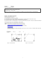
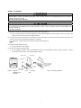
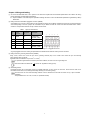
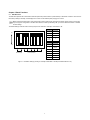
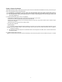
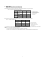
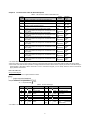
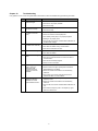
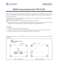
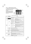
Instruction Manual DeviceNet Interface Card "OPC-F1-DEV" Thank you for purchasing our DeviceNet Interface Card OPC-F1-DEV. • This product is designed to connect the FRENIC-Eco series of inverters to DeviceNet. Read through this instruction manual and be familiar with the handling procedure for correct use. • Improper handling blocks correct operation or causes a short life or failure. • Deliver this manual to the end user of the product. The end user should keep this manual in a safe place until the DeviceNet Interface Card is discarded. • For the usage of inverters, refer to the instruction manual prepared for the FRENIC-Eco series of inverters. Fuji Electric Systems Co., Ltd. INR-SI47-0904-EU REV 052010 Copyright © 2004 Fuji Electric FA Components & Systems Co., Ltd. All rights reserved. No part of this publication may be reproduced or copied without prior written permission from Fuji Electric FA Components & Systems Co., Ltd. All products and company names mentioned in this manual are trademarks or registered trademarks of their respective holders. The information contained herein is subject to change without prior notice for improvement. Preface Thank you for purchasing our DeviceNet Interface Card OPC-F1-DEV. Installing this Card on your FRENIC-Eco allows you to connect the FRENIC-Eco to a DeviceNet master unit (e.g., PC and PLC) and control it as a slave unit using the RUN command, speed reference, and access to function codes. This product has been tested by ODVA authorized Independent Test Lab and found to comply with ODVA’s DeviceNet Conformance Test Version 18. Certification Logo Mark: DeviceNet is a trademark of Open DeviceNet Vendor Association, Inc. (ODVA). This manual is designed to serve as a quick guide to the installation and operation of the DeviceNet Interface Card. For a more complete description, refer to the DeviceNet Interface Card User’s Manual (MEHT274), which can be downloaded from the following URL (Fuji Electric FA Components & Systems, Co., Ltd. Technical Information): http://web1.fujielectric.co.jp/Kiki-Info-EN/User/index.html How this manual is organized This manual is made up of chapters 1 through 11. Chapter 1 Features Gives an overview of the main features of the DeviceNet Interface Card. Chapter 2 Acceptance Inspection Lists points to be checked upon delivery of the Card and precautions for transportation and storage of the Card. Also presents the appearance of the Card and provides information on how to obtain an EDS file. Chapter 3 Installation Provides instructions and precautions for installing the Card. Chapter 4 Wiring and Cabling Provides wiring and cabling instructions around the pluggable connector for the Card. Also gives the specifications for the cables. Chapter 5 Basic Functions Provides instructions on how to use the DIP switch to set the data rate (baud rate) and the node address. Also provides the meanings of the LED indicators. Chapter 6 Steps to Get Started Provides the procedures for getting the inverter started using DeviceNet. Chapter 7 I/O Assembly Instances: Selection and Setup Provides instructions on how to select the output assembly instances (request to the inverter) and the input assembly instances (response from the inverter) using the function codes o31 and o32. Also provides information on the factory default values and presents examples of setting and operation. Chapter 8 Other Parameters Provides instructions on how to set DNFaultMode (fault handling), NetCtrl (RUN command), and NetRef (Speed reference). Chapter 9 List of Function Codes for DeviceNet Option Lists the inverter's function codes which are specific to DeviceNet. Chapter 10 Troubleshooting Provides troubleshooting instructions for certain problems, e.g., when the inverter does not operate as ordered or when an alarm condition has been recognized. Chapter 11 Specifications Lists the general specifications and communications specifications. 1 Icons The following icons are used throughout this manual. This icon indicates information which, if not heeded, can result in the product not operating to full efficiency, as well as information concerning incorrect operations and settings which can result in accidents. This icon indicates information that can prove handy when performing certain settings or operations. This icon indicates a reference to more detailed information. Table of Contents Preface ................................................................................1 How this manual is organized ...............................................1 Chapter 1 Features .........................................................3 Chapter 2 Acceptance Inspection ...................................3 Chapter 3 Installation ......................................................4 Chapter 4 Wiring and Cabling .........................................5 Chapter 5 Basic Functions ..............................................6 5.1 SW3 DIP switch..............................................6 5.2 LED Status Indicators .....................................7 Chapter 6 Steps to Get Started .......................................8 Chapter 7 I/O Assembly Instances: Selection and Setup .....................................12 7.1 Output Assembly Instance (request to the inverter): set by o31 .............12 7.2 Input Assembly Instance (response from the inverter): set by o32 ......13 Chapter 8 Other Parameters .........................................16 8.1 DNFaultMode (Class 0x29, Instance 0x01, Attribute 0x10) ..............................................16 8.2 NetCtrl, NetRef (NetCtrl: Class 0x29, Instance 0x01, Attribute 0x05) (NetRef: Class 0x2A, Instance 0x01, Attribute 0x04) ......................17 Chapter 9 List of Function Codes for DeviceNet Option .........................................18 Chapter 10 Troubleshooting...........................................19 Chapter 11 Specifications...............................................20 11.1 General Specifications.................................20 11.2 DeviceNet Specifications .............................20 2 Chapter 1 Features The Card has the following features: - Data Rate (baud rate) : 125 kbps, 250 kbps, 500 kbps I/O Message : Polling and Change of State supported Applicable Profile : AC Drive profile Reading and writing all the function codes applicable to the FRENIC-Eco (User Defined Assembly I/O or Explicit Message) Chapter 2 Acceptance Inspection Unpack the package and check that: (1) A DeviceNet Card is contained in the package. (2) The DeviceNet Card has not been damaged during transportation--no defective electronic devices, dents, or warp. (3) The model name "OPC-F1-DEV" is printed on the DeviceNet Card. (See Figure 1.) If you suspect the product is not working properly or if you have any questions about your product, contact your Fuji Electric representative. This Card works with any version of the FRENIC-Eco series inverters. Neither an EDS file nor a terminating resistor comes with this Card. - An EDS file can be downloaded from any of the following Websites: http://web1.fujielectric.co.jp/Kiki-Info-EN/User/index.html (Fuji Electric FA Components & Systems Co., Ltd. Technical Information) http://www.odva.org (ODVA Headquarters) - A terminating resistor of the following specifications must be used: 121 ohm, 1/4 watt, 1% metal-film resistor (that usually comes with the master) SW3: DIP switch (for setting Baud Rate and MAC ID) Model Name 4 Spacers CN1 LEDs (Status Indicators) Figure 1 Back of the Card Figure 2 3 Front of the Card Chapter 3 Installation Turn the power off and wait for at least five minutes for models of 40 HP or below, or ten minutes for models of 50 HP or above, before starting installation. Further, check that the LED monitor is unlit, and check the DC link circuit voltage between the P (+) and N (-) terminals to be lower than 25 VDC. Otherwise, electric shock could occur. Do not touch any metallic part of the connector for the main unit (CN1) or any electronic component. Otherwise, electronic components may be damaged by static electricity. Also, the stain or adhesion of sweat or dust may adversely affect the contact reliability of the connector in the long run. An accident could occur. (1) Remove the covers from the inverter to expose the control printed circuit (Figure 3). For the removal instructions, refer to the FRENIC-Eco Instruction Manual (INR-SI47-1225-E), Chapter 2, Section 2.3 "Wiring." (For ratings of 50 HP or above, also open the keypad enclosure.) (2) Insert four spacers and connector CN1 on the back of the OPC-F1-DEV (Figure 2) into the four spacer holes and Port A (CN4) on the inverter's control printed circuit board (PCB) (Figure 4), respectively. Make sure, visually, that the spacers and CN1 are firmly inserted (Figure 5). (3) Install the wires for the OPC-F1-DEV. For wiring instructions, see Chapter 4. (4) Put the covers back to its original position. For the installation instructions, refer to the FRENIC-Eco Instruction Manual (INR-SI47-1225-E), Chapter 2, Section 2.3 "Wiring." (For ratings of 40 HP or above, also close the keypad enclosure.) Control PCB 4 Spacer Holes 4 Spacers Make sure that there is no space between control PCB and spacers. Port A (CN4) DeviceNet Card OPC-F1-DEV Figure 3 FRN010F1S-2U FRN020F1S-2U (example) CN1 Figure 4 Mounting the Card Figure 5 4 Mounting Completed Chapter 4 Wiring and Cabling (1) To connect the DeviceNet Card, use a special 5-core cable that complies with the DeviceNet specifications. Also observe the wiring lengths specified in the DeviceNet specifications. Proper installation of the cable requires specialist knowledge. Be sure to refer to the DeviceNet specifications (published by ODVA) beforehand. (2) Wiring around the DeviceNet’s pluggable connector (TERM1) A pluggable 5-pin connector is used (Figure 6).The pluggable connector has five labels corresponding to the five pins. Each label has a color corresponding to the wire (core) to be connected to its pin. Make sure that the colors of the wires and labels match. Table 1 shows the correspondence between the pin numbers and the colors. Table 1 Layout of Terminal Pins Color of Wire Sheath Pin Assignme nt 1 Black V- Power supply (24 VDC, - side) 2 Blue CAN_L Signal line 3 Metallic SHIELD Cable shield 4 White CAN_H Signal line 5 Red V+ Power supply (24 VDC, + side) Pin # Description 1 Figure 6 2 3 4 5 Pluggable Connector A typical pluggable connector meeting the specifications is MSTB 2.5/5-ST-5.08-AU made by Phoenix Contacts. (3) Wiring around the grounding terminal block (TERM2) Using a wire, connect one of the two pins to the grounding terminal (zG) on the inverter. Since these two pins are internally short-circuited, either one will do. 2 2 Applicable wire size: AWG20 to 16 (0.5 mm to 1.5 mm ) For protection against external noise and prevention of failures, be sure to connect a grounding wire. This terminal block is marked with E by its side. "E" signifies the earth (ground). (4) Terminating resistor DeviceNet requires that a terminating resistor be installed externally on each end of the trunk line. Check that the trunk line is terminated on both ends; if not, install (a) terminating resistor(s) on the missing end(s). The Card does not come with terminating resistors. Use the resistors that come with the master or buy a pair of resistors separately. The specifications are: 121 ohm, 1/4 watt, 1% (metal-film resistor) 5 Chapter 5 Basic Functions 5.1 SW3 DIP switch The DIP switch specifies the communication data rate (baud rate) and the MAC ID (node address) on DeviceNet. It offers a choice of three baud rates (125 kbps, 250 kbps, and 500 kbps) and a choice of node address (MAC) ranging from 0 to 63. Before accessing the DIP switch, make sure that the inverter’s power supply (including the auxiliary power supply) is turned OFF. If you change the configuration of the DIP switch with the inverter’s power being ON, you need to restart the inverter to validate the new settings. The default settings of the DIP switch at factory shipment are: data rate = 500 kbps, node address = 63. DR (bps) DIP 1-2 125K 00 250K 01 500K 10 Not allowed 11 NA DIP 3-8 0 000000 1 000001 2 000010 ON OFF 1 2 Data Rate (DR) Figure 7 3 4 5 6 7 8 3 000011 … … 62 111110 63 111111 Node Address (NA) DIP Switch Settings (showing an example of Data Rate = 500 kbps and Node Address = 63) 6 5.2 LED Status Indicators The two LED status indicators show the status of the Card. - MS (Module Status) Indicates the status of the DeviceNet Card hardware. - NS (Network Status) Indicates the status of communication on DeviceNet. The tables below show the states of the LEDs and their meanings. Table 2 MS LED State MS LED Meaning Blinks between*1 green and red Running self-diagnostic test upon power-on OFF Powered OFF – Lights in green Normal – Lights in red Hardware error (Card not properly installed or Card is faulty) Table 3 Note This test takes 1 second. The inverter shows er4. NS LED State NS LED Meaning Note Blinks between*1 green and red Running self-diagnostic test upon power-on OFF Not on-line (Checking for the duplicated MAC ID) – Blinks in green On-line and not connected (Waiting for a request from the master) – Lights in green On-line and connected (Communications link is established) – Blinks in red Connection time-out (The communications link is broken or the interval of I/O communication is too short.) *2 Lights in red Bus-off state or duplicated MAC ID has been detected. (E.g., Improper DeviceNet cabling, mismatch in data (baud) rate, and duplicated node address) The*2inverter shows er5 This test takes 1 second. The inverter shows er5 *1 Blinks in the pattern specified in the DeviceNet specifications. *2 er5 cannot be reset until communication is restored. A setting to ignore er5. is available. For details, refer to Chapter 8, Section 8.1 "DNFaultMode." 7 Chapter 6 Steps to Get Started This chapter presents the steps you take from the time the physical connection of DeviceNet is established to the time you start running the inverter with I/O Message using the DeviceNet master. I/O Message is a communication process in which cyclic data transmission takes place. Another communication process in DeviceNet is Explicit Message, in which event-driven data transmission takes place. Explicit Message allows you to directly read and set/modify function codes and DeviceNet parameters. For details on Explicit Message, refer to the DeviceNet Interface Card User’s Manual (MEHT274). (1) Set the DeviceNet master (PLC, PC tool, or Configurator). - Set the MAC ID (node address) uniquely, so that it does not coincide with any other nodes. - Set the baud rate. Make sure that all the nodes have the same baud rate. - Allocate an I/O area corresponding to the I/O assembly instance set for this Card. The I/O area is either 4 bytes or 8 bytes in length. See (3) on the next page. - Specify the type of I/O connection (Poll or Change of state). In the case of the Configurator, - Install the EDS file. The Electric Data Sheet (EDS) file defines parameters on the slave. Using it quickly accesses the desired parameters. For this Card, the file makes it easier to access the inverter's function codes. For how to obtain the EDS file, refer to Chapter 2 "Acceptance Inspection." The exact setting procedures depend on the DeviceNet master or the Configurator. For details, refer to the User’s Manual of the corresponding master. (2) Configure the DIP switch on this Card. Before accessing the DIP switch (baud rate and node address), make sure that the power is OFF. For details, see Figure 7 in Chapter 5. 8 (3) Set the function codes for the inverter. Power ON the inverter and set the function codes according to the table below. - o31, o32 Select the I/O assembly instances (I/O formats). o31 is for the output (from master to inverter); o32 is for the input (from inverter to master). You can specify any combination of input (o31) and output (o32). After modifying the I/O assembly instances, restart the inverter to validate the new settings on the inverter. Once you have modified the settings for o31 or o32, be sure to restart the inverter in order to validate the new settings. Table 4 Setting o31 and o32 Length (bytes) o31, o32 Type Instance ID o31=20 Output (from master to slave) 20 Basic Speed Control Output 4 21 Extended Output 4 o31=100 100 Fuji Drive Assembly Output 4 o31=102 102 User Defined Assembly Output 8 70 Basic Speed Control Input 4 71 Extended Speed Control Input 4 o32=101 101 Fuji Drive Assembly Input 4 o32=103 103 User Defined Assembly Input 8 o31=21 or 0 (initial value) o32=70 o32=71 or 0 (initial value) Input (from slave to master) Description Speed Control For the details of instances, refer to Chapter 7. (4) Set other parameters as necessary. a) DNFaultMode This parameter specifies the operation to be performed if a DeviceNet communications error occurs. The factory default is "Trip immediately with er5 if a DeviceNet communications error occurs." (Class 0x29; Instance 1; Attribute 16) For details, refer to Chapter 8. b) NetCtrl, NetRef The NetCtrl parameter enables/disables the RUN command sent via DeviceNet; and the NetRef parameter, the Speed reference. Their factory defaults are "disabled." (NetCtrl: Class 0x29, Instance 1, Attribute 5) (NetRef: Class 0x2A, Instance 1, Attribute 4) For details, refer to Chapter 8. NetCtrl and NetRef can also be specified from I/O Assembly Instance 21 (see the next page). (5) Have an I/O connection request issued from the DeviceNet master. In order for this Card to start DeviceNet communication, the master should send a communication request. For details, refer to the User’s Manual of the master. Once I/O connection is established between the master and the slave, the NS LED on this Card changes from blinking green to solid green, and communication starts. Set the I/O scan interval (=EPR) for the Card during I/O connection to at least 10 ms (For example, 10 ms if one master controls one slave; 5 ms if one master controls two slaves). It is recommended that you specify at least 20 ms to the I/O scan interval to minimize the frequency of communications collision and maximize the system’s reliability. 9 (6) Examples of I/O communication Presented herein are examples of the format of the I/O Assembly Instance at shipment from the factory. a) Description of Format o31 = 21 or 0 Output Assembly Instance ID.21 (output from the master = request to the inverter) Instance byte bit 7 bit 6 bit 5 bit 4 bit 3 21 0 - NetRef NetCtrl - 1 2 3 (Fixed at 00) Speed Reference (lower byte) (r/min) Speed Reference (upper byte) (r/min) - bit 2 Fault Reset bit 1 Run Reverse bit 0 Run Forward Run Forward: Run Reverse: Fault Reset: NetCtrl: 1 = Run Forward command 1 = Run Reverse command 1 = Reset the alarm condition 1 = Request for enabling Run command sent from DeviceNet 0 = Request for enabling Run command sent from other than DeviceNet NetRef: 1 = Request for enabling Speed Reference sent from DeviceNet 0 = Request for enabling Speed Reference sent from other than DeviceNet Speed Reference: Speed Reference (in r/min) o32 = 71 or 0 Input Assembly Instance ID.71 (input to the master = response from the inverter) Instance byte bit 7 bit 6 bit 5 bit 4 bit 3 71 0 Ready At Ref_ Ctrl_ Reference From_Net From_Net 1 2 Drive State Speed Actual (lower byte) (r/min) 3 Speed Actual (upper byte) (r/min) Running Reverse bit 2 Running Forward bit 1 - bit 0 Faulted Faulted: 1 = The inverter has (and remains) tripped. Running Forward: 1 = The motor is running forward. Running Reverse: 1 = The motor is running backward (in the reverse direction). Ready: 1 = Ready to run Ctrl_From_Net: 1 = Run command sent from DeviceNet being enabled 0 = Run command sent from other than DeviceNet being enabled Ref_From_Net: 1 = Speed Reference sent from DeviceNet being enabled 0 = Speed Reference sent from other than DeviceNet being enabled At Reference: 1 = The motor is running at the reference speed. Drive State: 3 = Ready, 4 = Enabled, 5 = Stopping, 6 = Fault stop, 7 = Faulted, 1 = Startup, 2 = Not Ready Speed Actual: Actual rotation speed (in r/min) b) Actual I/O Data during Running Presented below are an example of the driving pattern for controlling the inverter and its corresponding I/O data expressed in the format given above. Forward 1800 r/min Time (s) 300 r/min 1800 r/min Reverse Figure 8 Driving Pattern 10 Description of I/O Data (The I/O data are in hexadecimal notation.) Request: Run command is OFF. Speed Reference = 1800 r/min (= 0708h). Run command and Speed Reference via DeviceNet are enabled. 60 00 08 07 Response: Stopping. The inverter is ready. 70 03 00 00 Request: Run Forward command. Speed Reference = 1800 r/min (= 0708h). Run command and Speed Reference via DeviceNet are enabled. 61 00 08 07 Response: The motor is running forward and accelerating. The actual speed is increasing. 74 04 ** ** Request: Run Forward command. Speed Reference = 1800 r/min (= 0708h). Run command and Speed Reference via DeviceNet are enabled. 61 00 08 07 Response: Running Forward. The actual speed has reached the Reference F4 04 08 07 Request: Run command is OFF. Speed Reference = 1800 r/min (= 0708h). Run command and Speed Reference via DeviceNet are enabled. 60 00 08 07 Response: The motor is running forward and decelerating. The actual speed is decreasing. 74 05 ** ** Request: No RUN command. Speed Reference is changed to 300 r/min (= 012Ch). Run command and Speed Reference via DeviceNet are enabled. 60 00 2C 01 Response: Stopping. The inverter is ready. 70 03 00 00 Request: Reverse command. Speed Reference = 300 r/min (= 012Ch). Run command and Speed Reference via DeviceNet are enabled. 62 00 2C 01 Response: The motor is running backward (in the reverse direction) and accelerating. The actual speed is increasing. 78 04 ** ** Request: Reverse command. Speed Reference = 300 r/min (= 012Ch). Run command and Speed Reference via DeviceNet are enabled. 62 00 2C 01 Response: Running in the reverse direction. The actual speed has reached Reference F8 04 2C 01 Request: Reverse command. Speed Reference is changed to 1800 r/min (= 0708h). Run command and Speed Reference via DeviceNet are enabled. 62 00 08 07 Response: The motor is running backward (in the reverse direction) and accelerating. The actual speed is increasing. 78 04 ** ** Request: Reverse command. Speed Reference = 1800 r/min (= 0708h). Run command and Speed Reference via DeviceNet are enabled. 62 00 08 07 Response: Running in the reverse direction. The actual speed has reached Reference F8 04 08 07 Request: Run command is OFF. Speed Reference = 1800 r/min (= 0708h). Run command and Speed Reference via DeviceNet are enabled. 62 00 08 07 Response: The motor is running backward (in the reverse direction) and decelerating. The actual speed is decreasing. 78 05 ** ** 11 Chapter 7 I/O Assembly Instances: Selection and Setup 7.1 Output Assembly Instance (request to the inverter): set by o31 (1) o31 = 20 Output Assembly Instance ID.20 Instance byte 20 Basic Speed Control Output bit 7 bit 6 0 - - 1 (Fixed at 00) bit 5 bit 4 - - 2 Speed Reference (lower byte) (r/min) 3 Speed Reference (upper byte) (r/min) bit 3 bit 2 - Fault Reset bit 1 - bit 0 Run Forward Run Forward: 1 = Run Forward command Fault Reset: 1 = Reset the alarm condition Speed Reference: Speed Reference (in r/min) (2) o31 = 21 or 0 (factory default) Output Assembly Instance ID.21 Instance byte 21 Extended Speed Control Output bit 7 bit 6 bit 5 NetRef NetCtrl 0 - 1 (Fixed at 00) bit 4 - 2 Speed Reference (lower byte) (r/min) 3 Speed Reference (upper byte) (r/min) bit 3 bit 2 - Fault Reset bit 1 Run Reverse bit 0 Run Forward Run Forward: Run Reverse: Fault Reset: NetCtrl: 1 = Run Forward command 1 = Run Reverse command 1 = Reset the alarm condition 1 = Request for enabling Run command sent from DeviceNet; 0 = Request for enabling Run command sent from other than DeviceNet NetRef: 1 = Request for enabling Speed Reference sent from DeviceNet; 0 = Request for enabling Speed Reference sent from other than DeviceNet Speed Reference: Speed Reference (in r/min) (3) o31 = 100 Output Assembly Instance ID.100 Fuji Drive Assembly Output Instance byte 100 bit 7 bit 6 bit 5 bit 4 bit 3 bit 2 bit 1 bit 0 0 - X5 X4 X3 X2 X1 REV FWD 1 RST XR XF - - - - - 2 Frequency command p.u. (lower byte) 3 Frequency command p.u. (upper byte) FWD: REV: X1 to X5: Run command (same as S06) Frequency command (same as S01) 1 = Run Forward command 1 = Run Reverse command Communication Terminal Block command (The exact function to be performed is specified by E01 – E05). XF, XR: Communication Terminal Block command (The exact function to be performed is specified by E98 and E99). RST: 1 = Reset the alarm (fault) condition. Frequency command p.u.: Specifies the ratio of the frequency to the data of 20000 for the maximum frequency F03. That is, Frequency command p.u. = Frequency command (Hz)/F03 (Hz) 20000. 12 (4) o31 = 102 Output Assembly Instance ID.102 User Defined Assembly Output User Defined Assembly Output offers a format which allows the user to freely set or modify the function code defined by the user beforehand. Four function codes are provided for the user to define. Instance byte 102 bit 7 bit 6 bit 5 bit 4 bit 3 bit 2 bit 1 bit 0 0 User-defined function code 1 (write) (lower byte) (data of function code specified by o40) 1 User-defined function code 1 (write) (upper byte) (data of function code specified by o40) 2 User-defined function code 2 (write) (lower byte) (data of function code specified by o41) 3 User-defined function code 2 (write) (upper byte) (data of function code specified by o41) 4 User-defined function code 3 (write) (lower byte) (data of function code specified by o42) 5 User-defined function code 3 (write) (upper byte) (data of function code specified by o42) 6 User-defined function code 4 (write) (lower byte) (data of function code specified by o43) 7 User-defined function code 4 (write) (upper byte) (data of function code specified by o43) User-defined function code 1 (write): write data for the function code specified by o40 User-defined function code 2 (write): write data for the function code specified by o41 User-defined function code 3 (write): write data for the function code specified by o42 User-defined function code 4 (write): write data for the function code specified by o43 Once you have modified the settings for o40 to o43, be sure to restart the inverter in order to validate the new settings. For details of the write formats for individual function codes, refer to the DeviceNet Interface Card User’s Manual (MEHT274). If you assign the same function code to more than one "o" code, only the one assigned to the smallest "o" code number will become effective, and all the rest will be ignored (treated as "not assigned"). 7.2 Input Assembly Instance (response from the inverter): set by o32 (1) o32 = 70 Input Assembly Instance ID.70 Instance byte 70 Basic Speed Control Input bit 7 bit 6 - bit 5 0 - - 1 (00) 2 Speed Actual (lower byte) (r/min) 3 Speed Actual (upper byte) (r/min) bit 4 - bit 3 - Faulted: 1 = The inverter has (and remains) tripped Running Forward: 1 = The motor is running forward. Speed Actual: Actual rotation speed (in r/min) 13 bit 2 Running Forward bit 1 - bit 0 Faulted (2) o32 = 71 or 0 (factory default) Input Assembly Instance ID.71 Instance byte 71 0 Extended Speed Control Input bit 7 bit 6 bit 5 bit 4 At Ref_ Ctrl_ Ready Reference From_Net From_Net 1 Drive State 2 Speed Actual (lower byte) (r/min) 3 Speed Actual (upper byte) (r/min) bit 3 bit 2 Running Reverse bit 1 Running Forward - bit 0 Faulted Faulted: 1 = The inverter has (and remains) tripped. Running Forward: 1 = The motor is running forward. Running Reverse: 1 = The motor is running backward (in the reverse direction). Ready: 1 = Ready to run Ctrl_From_Net: 1 = Run command sent from DeviceNet being enabled 0 = Run command sent from other than DeviceNet being enabled Ref_From_Net: 1 = Speed Reference sent from DeviceNet being enabled 0 = Speed Reference sent from other than DeviceNet being enabled At Reference: 1 = The motor is running at the reference speed. Drive State: 3 = Ready, 4 = Enabled, 5 = Stopping, 6 = Fault stop, 7 = Faulted, 1 = Startup, 2 = Not Ready Speed Actual: Actual rotation speed (in r/min) (3) o32 = 101 Input Assembly Instance ID.101 Fuji Drive Assembly Input Instance byte bit 7 bit 6 bit 5 bit 4 bit 3 bit 2 bit 1 bit 0 101 0 VL TL NUV BRK INT EXT REV FWD 1 BUSY ERR - RL ALM DEC ACC IL 2 Frequency output p.u. (lower byte) 3 Frequency output p.u. (upper byte) Running status (same as M14) Output frequency (same as M06) FWD: During forward rotation REV: During reverse rotation EXT: During DC braking (or during pre-exciting) INT: Inverter shut down BRK: During braking NUV: DC link circuit voltage established (0 = undervoltage) TL: During torque limiting VL: During voltage limiting IL: During current limiting ACC: During acceleration DEC: During deceleration ALM: Alarm relay (for any fault) RL: Communications effective ERR: Function code access error BUSY: During function code data writing Frequency output p.u.: Output frequency. Expressed as the ratio of the frequency to the data of 20000 for the maximum frequency F03. That is, Frequency command p.u. = Frequency command (Hz)/F03 (Hz) 20000. 14 (4) o32 = 103 Input Assembly Instance ID.103 User Defined Assembly Input User Defined Assembly Input offers a format which allows the user to monitor the function codes defined by the user beforehand. Four function codes are provided for the user to define. Instance byte 103 bit 7 bit 6 bit 5 bit 4 bit 3 bit 2 bit 1 bit 0 0 User-defined function code 1 (read) (lower byte) (data of function code specified by o48) 1 User-defined function code 1 (read) (upper byte) (data of function code specified by o48) 2 User-defined function code 2 (read) (lower byte) (data of function code specified by o49) 3 User-defined function code 2 (read) (upper byte) (data of function code specified by o49) 4 User-defined function code 3 (read) (lower byte) (data of function code specified by o50) 5 User-defined function code 3 (read) (upper byte) (data of function code specified by o50) 6 User-defined function code 4 (read) (lower byte) (data of function code specified by o51) 7 User-defined function code 4 (read) (upper byte) (data of function code specified by o51) User-defined function code 1 (read): value of the function code specified by o48 User-defined function code 2 (read): value of the function code specified by o49 User-defined function code 3 (read): value of the function code specified by o50 User-defined function code 4 (read): value of the function code specified by o51 Once you have modified the settings for o48 to o51, be sure to restart the inverter in order to validate the new settings. For details of the formats for individual function codes, refer to the DeviceNet Interface Card User’s Manual (MEHT274). 15 Chapter 8 Other Parameters 8.1 DNFaultMode (Class 0x29, Instance 0x01, Attribute 0x10) This parameter specifies the inverter operation to be performed if a DeviceNet communication error occurs. Using the function code o27, you can also specify the operation in the event of a communication error in the same way as with DNFaultMode. The "o27" column in the table below shows the value for o27 corresponding to that of DNFaultMode. Table 5 Inverter Operations Specified by DNFaultMode DNFaultMo de Inverter Operation in the Event of an Error Note o27 0 Turn OFF Run command immediately. (No error er5 occurs.) 1 Ignore the error. (No error er5 occurs.) 2 Ignore the error if the communications link is restored within the timer value specified by o28. If the timer value is exceeded, then decelerate the motor by force and then turn on er5. The forced deceleration period is specified by F08. 12 3 Put the motor in forward rotation by force. (No error er5 occurs.) Forward rotation is enabled when NetCtrl = 1. 14 4 Put the motor in reverse rotation by force. (No error er5 occurs.) Reverse rotation is enabled when NetCtrl = 1. 15 100 Put the motor immediately in coast-to-stop mode and cause an er5 trip. 0 101 Put the motor in coast-to-stop mode and cause an er5 stop when the time set by o28 (Timer) has expired. 1 102 Ignore the alarm condition if the communications link is restored within the timer value specified by o28. If the timer value is exceeded, then put the motor in coast-to-stop mode by force and then turn on er5. 2 110 Immediately decelerate the motor by force. When the motor has stopped, turn on er5. The forced deceleration period is specified by F08. 10 111 When the time set by o28 (Timer) has expired, put the motor in coast-to-stop mode and, when the motor has stopped, turn on er5 . The forced deceleration period is specified by F08. 11 112 Same as for [DNFaultMode = 2] *1 13 3 12 *1 o27 can have values in the range of 0 to 15. If you specify a value not shown in Table 5 (o27 = 4 to 9), the same operation as for o27 = 0 will be performed. 16 8.2 NetCtrl, NetRef (NetCtrl: Class 0x29, Instance 0x01, Attribute 0x05) (NetRef: Class 0x2A, Instance 0x01, Attribute 0x04) These parameters specify whether to enable the Run command and Speed Reference coming via DeviceNet. Table 6 Operations Specified by NetCtrl and NetRef RUN Command Setting NetCtrl NetRef Speed Reference 0 (factory default) N – 1 Y – 0 (factory default) – N 1 – Y Y: Possible via DeviceNet N: Impossible via DeviceNet (Possible via keypad, external terminal block, etc.) –: Not available Using the function code y98, you can also specify the operation in the same way as with NetCtrl and NetRef. Table 7 Operations Specified by y98 Speed Reference RUN Command 0 (factory default) N N 1 Y N 2 N Y 3 Y Y y98 Y: Possible via DeviceNet N: Impossible via DeviceNet (Possible via keypad, external terminal block, etc.) Depending on how the inverter is set (*), the RUN command and Speed Reference coming via DeviceNet may not be enabled, even if you set NetCtrl and NetRef as shown above. (*) function code y99, LE (link operation selection), and selection of local/remote. For details, refer to the FRENIC-Eco User’s Manual (MEH456), Chapter 4 "BLOCK DIAGRAMS FOR CONTROL LOGIC." 17 Chapter 9 List of Function Codes for DeviceNet Option Table 8 List of Function Codes for DeviceNet Card Functio Description n Code o27 Selection of operation in the event of DeviceNet error o28 Timer for start of operation in the event of Error *1 o31 Selection of Output Assembly Instance o32 *1 Selection of Input Assembly Instance o40 *1 o41 *1 o42 *1 o43 *1 o48 *1 o49 *1 o50 *1 o51 *1 Assignment of user-defined function code 1 (write) Function code data to be assigned to user-defined code 1 (write} Assignment of user-defined function code 2 (write) Function code data to be assigned to user-defined code 2 (write} Assignment of user-defined function code 3 (write) Function code data to be assigned to user-defined code 3 (write} Assignment of user-defined function code 4 (write) Function code data to be assigned to user-defined code 4 (write} Assignment of user-defined function code 1 (read) Function code data to be assigned to user-defined code 1 (read) Assignment of user-defined function code 2 (read) Function code data to be assigned to user-defined code 2 (read) Assignment of user-defined function code 3 (read) Function code data to be assigned to user-defined code 3 (read) Assignment of user-defined function code 4 (read) Function code data to be assigned to user-defined code 4 (read) Factory Default 0 5.0s 0 (=21) 0 (=71) 0000 function (no assignment) 0000 function (no assignment) 0000 function (no assignment) 0000 function (no assignment) 0000 function (no assignment) 0000 function (no assignment) 0000 function (no assignment) 0000 function (no assignment) Allowable Range 0 - 15 0.0 - 60.0s 0, 20, 21,*2 100, 102 0, 70, 71,*2 101, 103 any function *3 code any function *3 code any function *3 code any function *3 code any function *3 code any function *3 code any function *3 code any function *3 code *1 To validate these new settings, you need to restart the inverter. *2 The entry range is from 0 to 255; however, specifying a value other than those given in this table resets the data to the factory default. *3 The function code data should be specified in a 4-digit hexadecimal format as shown below. To specify the function code data through a remote keypad or DeviceNet, observe this format. To use a multi-function keypad, you can directly select the function code without paying attention to that format. How to set o40 to o51 Using a remote keypad Specify the function code in a 4-digit hexadecimal notation. Example: For H30: H Type Code 08 30 1E (hexadecimal) 081e Table 9 Type Type Code S 2 0x02 M 3 0x03 F 4 0x04 E C P 5 6 7 0x05 0x06 0x07 H 8 0x08 Function Code Command/function data Monitored data Fundamental function Terminal function Control function Motor 1 function High performance function Function Code Type Type Type Code Function Code o 10 0x0A Optional function J 14 0x0E Application function y 15 0x0F Link function W X Z conve ntional 16 17 18 0x10 0x11 0x12 0 0x00 Monitor 2 Alarm 1 Alarm 2 Function codes for the G11’s DeviceNet Interface Card* * For details on the G11’s function codes, refer to the User’s Manual of DeviceNet Interface Card (MEHT274). 18 Chapter 10 Troubleshooting If any problem or error occurs during DeviceNet communication, follow the troubleshooting procedures given below. No Phenomenon/Symptom Probable Causes 1 None of the LEDs on the Card would light. The inverter is not powered ON. The Card is not properly installed. The Card is faulty. 2 3 er4 alarm cannot be reset (MS LED is lit in red). The Card is not properly installed. NS LED is lit in red. (er5 alarm cannot be reset.) There is a duplicated node address. The Card is faulty. There is a mismatch in baud (data) rate. The network power (24V) is not properly supplied. Cabling is not properly done. The inverter has not been restarted after modification of the DIP switch settings. 4 NS LED is blinking in red. (er5 alarm has occurred.) The master has a problem. The cable was broken during communication. The I/O scan interval is too short. 5 NS LED would not light. The master has a problem. The cable was broken. 6 NS LED would not light in green. The master has a problem. The I/O scan interval was set too short at the start of communication. The I/O area is invalidly mapped. There is no I/O connection. 7 Even though NS LED lights in green, the settings for RUN command or Speed Reference cannot be validated. Neither NetCtrl nor NetRef is set to “1.” On the inverter, the higher-priority RUN command or Speed Reference is enabled. There is a mistake in the selection of I/O Assembly Instances. The inverter has not been powered OFF and then powered ON after o31 was modified. 8 Although the Speed Reference has been validated, the actual speed is different from it. The number of motor poles specified by P01 does not match the motor. There is a mistake in the selection of I/O Assembly Instances. The inverter has not been restarted after modification of o31. The maximum frequency F03 or the frequency upper limit F15 is set too low. 19 Chapter 11 Specifications 11.1 General Specifications For the items not covered in this section, the specifications of the inverter apply. Item Specifications Input power Operating range 130 mA at maximum (5 VDC) ambient temperature -10 to +85C(14 to +185F) Operating ambient humidity range 5 to 95% RH (There shall be no condensation.) External dimensions 94 x 63 x 23.5 mm(3.7 x 2.48 x 0.93 in) Applicable inverter FRENIC-Eco 11.2 DeviceNet Specifications For the items not covered in this section, the DeviceNet Specifications Release 2.0 apply. Item Specifications Network input voltage 11 V to 28 V Network input power 50 mA at maximum (24 VDC) No. of nodes connected 64 at maximum (including the master) MAC ID 0 to 63 Insulation 500 VDC (photocoupler insulation) Transmission rate 500 kbps/250 kbps/125 kbps Maximum cable length (Trunk line: thick cable Drop line: thin cable) Transmission rate 500 kbps 250 kbps 125 kbps Trunk line length 100 m (328 ft) 250 m (820 ft) 500 m (1640 ft) Drop line length 6m (19.7 ft) 6m (19.7 ft) 6m (19.7 ft) Total length of drop lines 39 m (128 ft) 78 m (256 ft) 156 m (512 ft) Messages supported 1. I/O Message (poll, change of state) 2. Explicit Message Vendor ID 319 (Fuji Electric Co., Ltd.) Device type AC drive (code: 2) Product code 9217 Model name OPC-F1-DEV Applicable device profile AC Drive No. of input/output bytes Selectable between 4 and 8 bytes for input and output (independently) Applicable DeviceNet Specifications DeviceNet Specifications Release 2.0 Errata 5 (Certified by ODVA Japan for Conformance Test Version A-18) Node type Group 2 only server 20 DeviceNet Interface Card "OPC-F1-DEV" Instruction Manual First Edition, September 2004 Fuji Electric FA Components & Systems Co., Ltd. The purpose of this manual is to provide accurate information in the handling, setting up and operating of DeviceNet Interface Card "OPC-F1-DEV" for the FRENIC-Eco series of inverters. Please feel free to send your comments regarding any errors or omissions you may have found, or any suggestions you may have for generally improving the manual. In no event will Fuji Electric FA Components & Systems Co., Ltd. be liable for any direct or indirect damages resulting from the application of the information in this manual. MEMO Fuji Electric Systems Co., Ltd. Fuji Electric Corp. of America 47520 Westinghouse Drive Fremont, CA 94539, U.S.A. Tel.+1-510-440-1060 Fax.+1-510-440-1063 Toll-free support 1-888-900-FUJI(3854) INR-SI47-0904-EU Rev 052010 http://www.fujielectric.com/fecoa/ Information subject to change without notice.