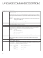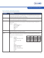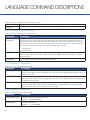
1
USER MANUAL
V1.1
XL SERIES
BASIC PROGRAMMING GUIDE
D40-02 0615
CONTENTS & WARRANTY
This user manual is a BASIC programming guide for the XL Data Logger Series (H-350XL, H-500XL, H-522+,
H-522) . For more information, updated manuals, brochures, technical notes, and supporting software on the
XL Series, please refer to waterlog.com or contact your sales representative.
For additional assistance, please contact us at +1.435.753.2212 or [email protected]
Warranty.................................................................................1
Chapter 1: Variables............................................................2
Basic 1 to Basic 5.................................................................3
Variables...............................................................................3
The basicx Variable............................................................. 3
General Purpose Variables.................................................4
Standard Input Variables.................................................... 4
Read Only Variables............................................................5
Chapter 2: Math Functions.................................................6
Basic Math Operations....................................................... 7
Trigonometry Operations.................................................. 7
Logarithmic Operations..................................................... 7
Misc Function Operations.................................................. 7
Chapter 3: XL-BASIC Command Summary.....................8
Program Flow / Control Commands.................................9
Sensor Input Commands................................................... 9
Com Port Commands......................................................... 9
Built-in Display / Keypad Commands.............................10
Data Card and File Comands.......................................... 10
H-355 Bubbler Commands..............................................10
Miscellaneous Commands...............................................11
Chapter 4: Language Command Descriptions............12
Program Flow / Control Commands...............................13
Sensor Input / Misc I/O Functions...................................14
Com Port Commands....................................................... 15
Built-in Display / Keypad Commands.............................17
Data Card and File Commands.......................................18
H-355 Bubbler Commands..............................................18
Miscellaneous Commands...............................................18
Chapter 5: Creating XL-BASIC Programs......................20
XL-Basic Menu Screens.................................................... 21
PC Interface View.............................................................. 22
Chapter 6: Examples & Version Changes.....................23
Example XL-BASIC Programs.......................................... 24
Version Changes.............................................................. 25
Contents & Warranty
Warranty
“WATERLOG™ PRODUCTS MANUFACTURED BY YELLOW SPRINGS INSTRUMENTS CO., INC. are warranted
by Yellow Springs Instruments Co., Inc. (“YSI”) to be free from defects in materials and workmanship under
normal use and service for twelve (12) months from date of shipment unlessotherwise specified in the
corresponding YSI pricelist or product manual.
WaterLOG™ products not manufactured, but that are re-sold by YSI, are warranted only to the limits extended
by the original manufacturer. Batteries, desiccant, and other consumables have no warranty. YSI’s obligation
under this warranty is limited to repairing or replacing (YSI’s option) defective products,which shall be the
sole and exclusive remedy under this warranty.
The customer shall assume all costs of removing, reinstalling, and shipping defective products to YSI. YSI will
return such products by surface carrier prepaid within the continental United States of America. To all other
locations, YSI will return such products best way CIP (Port of Entry) INCOTERM® 2010, prepaid. This warranty
shall not apply to any products which have been subjected to modification, misuse, neglect, improper service,
accidents of nature, or shipping damage. This warranty is in lieu of all other warranties, expressed or implied.
The warranty for installation services performed by YSI such as programming to customer specifications,
electrical connections to products manufactured by YSI, and product specific training, is part of YSI’s product
warranty. YSI EXPRESSLY DISCLAIMS AND EXCLUDES ANY IMPLIED WARRANTIES OF MERCHANTABILITY
OR FITNESS FOR A PARTICULAR PURPOSE. YSI is not liable for any special, indirect, incidental, and/or
consequential damages.”
A complete TERMS AND CONDITIONS OF SALE can be viewed at:
http://www.ysi.com/terms-and-conditions.php
1
01 /
2
VARIABLES
Variables
The WaterLOG® XL™ series data loggers have a built in BASIC interpreter for handling specialized operations
outside the normal use of the data logger. Since this BASIC interpreter is specific to the XL™ series of data
loggers it is called XL-BASIC. XL-BASIC handles many of the standard BASIC commands, but also provides
accesses to the I/O and other features of the XL™ series data logger.
Basic 1 to Basic 5
There are five basic programs that can be called anytime the system is collecting data to log or to send to
the GOES radio, etc. To execute one of the five programs, select it from the source list just as “Stage” or
“Ana1” is selected. Each XL-BASIC program has a defined variable that will be used as a return value for the
function that caused the XL-BASIC program to execute. For example, as the system processes the data to
log, it looks at the source column1. Column 2 is normally time and a time stamp is placed in this column.
If column 3 source was set to “Basic1”, then the Basic 1 program would execute and the value in variable
“Basic1” would be placed in the third column.
A BASIC program is written using a standard text editor on a PC and then loaded into the XL™ series
data logger. Each BASIC program must be 8K bytes or less in size. The size of the program includes all
commands, comments, remarks and spacing. If the size of the file becomes too big, then cut down on the
remarks, spacing, or break the tasts into two separate programs.
Variables
The system is limited on RAM, and to keep the operation of the BASIC programming simple, only predefined
variables will be used. All variables types will be double precision floating point variables. All standard system
variables will be accessible to the XL-BASIC interpreter plus some generic variables used only by the XLBASIC interpreter system. In the program, the variables may be upper or lower case. Below, they are shown
in lower case.
Table 1-1: Main BASIC Program Variables
Variable Name
Type
basic1
Read / Write
basic2
basic3
basic4
basic5
Description
These variables are used to return values from Basic program
1 to 5, to the menu option calling the BASIC program. These
variables are initialized to 0.0 when scanning is enabled, and
will retain any modifications between scans. On return, the
value will depend on the users BASIC program.
The basicx Variable
This is not a separate variable, but is actually an indirect link to one of the normal basic variables 1 to 5. A
program can return a value using the variable associated to the location number where the basic program
is loaded. For example, a program loaded into basic program location 1 must use the variable basic1 as the
return variable. Now a program can use the name basicx as the return variable which allows the program to
be loaded in any program location. If loaded into program location 3, when the program updates the basicx
variable, it is actually updating the variable basic3.
3
VARIABLES
General Purpose Variables
Table 1-2: General Purpose Variables
Variable Name
Type
a to z
Read / Write
Description
26 General purpose variables initialized to 0.0 when scanning
is enabled. Any value changes will be retained between
program execution and between scans.
Standard Input Variables
Table 1-3: Standard Input Variables
Variable Name Type
Description
Stage
Read / Write
The last measured stage value is returned. (Only available on the H-350XL and
the H-510XL)
LastStage
Read / Write
The stage value measured on the previous scan will be returned. (Only available
on the H-350XL)
PtTemp
Read / Write
The last measured PtTemp value is returned. (Only available on the H-350XL)
PSI
Read / Write
The last measured PSI value is returned. (Only available on the H-350XL)
AnaX
Read / Write
The last measured value for analog channel X (X=1 to 4) is returned.
Freq
Read / Write
The last measured freq value is returned.
Digio1
Read / Write
The last measured input state for digital channel 1 is returned.
Digio2
Read / Write
The last measured input state for digital channel 2 is returned.
Counts
Read / Write
The last measured count value is returned.
Totcnt
Read / Write
The last measured total count value is returned.
Countrate
Read / Write
The current count rate on the counter input.
Encodr
Read / Write
The last measured encoder input value is returned.
Tscans
Read / Write
The total scans value is returned
SdiAP
Read / Write
The last measured value for the selected SDI-12 variable is returned A = address
0 to 9, P = parameter 1 to 9
FntXX
Read / Write
The last calculated value for function XX is returned. (XX = 01 to 40)
BasicX
Read / Write
The value of one program can be used in other programs. (X = 1 to 5)
Note: Standard input variables are normally read only, but may also be assigned a new value directly in the
XL-BASIC program regardless of the variables corresponding hardware input condition. Be aware that based
on system configuratin, the input variable could be updated by the system after the variable was set by the
XL BASIC program. Writing to these variables should be avoided or only used in advanced applications. For
example, in the following segment of code, the second line makes the first line useless.
measure(ana1)
ana1 = 12.34
4
Measurement analog input 1 now and update its variable
Sets variable ana1 to 12.34 regardless of the voltage on analog 1
Variables
Read Only Variables
Table 1-4: Read Only Variables
Variable Name Type
Description
Date
Read Only
The date is returned in the format YYMMDD.0000
Time
Read Only
The time is returned in the format HHMMSS.0000
seconds
Read Only
Return the current seconds in the format SS.0000
minutes
Read Only
Return the current minutes in the format MM.0000
hours
Read Only
Return the current hours in the format HH.0000
day
Read Only
Return the current day in the format DD.0000
month
Read Only
Return the current month in the format MM.0000
year
Read Only
Return the current year in the format YY.0000
Batt
Read Only
The current battery voltage reading is returned
minbatt
Read Only
Return the minimum battery voltage measured since option was reset
maxbatt
Read Only
Return the maximum battery voltage measured since option was reset
tankpsi
Read Only
Return H-355 tank PSI if an H-355 is connected
linepsi
Read Only
Return H-355 line PSI if an H-355 is connected
purgepsi
Read Only
Returns H-355 purge PSI setting
purgedur
Read Only
Returns H-355 purge duration setting
bubrate
Read Only
Returns H-355 bubble rate setting
Purge
Read Only
Returns H-355 purge status,
Resets
Read Only
Returns the number of times the system has reset
LogvalX
Read Only
Returns the value associated to a log column when the column is setup to
perform some function on the data like calculating the average, etc. The ‘X’ is
the log column 01 to 25
0 = bubbler communication error
1 = request for purge accepted
2 = already purging
Note: The read only variables may be read but should not be written. Trying to set of write on of these
variables to some value will have no affect, and the program will continue on under normal operation. If one
of these variables is set to some value and then read again, the value returned will not be the value set by the
program, but will be a value based on the function behind the variable.
5
02 /
6
MATH FUNCTIONS
Math Functions
Basic Math Operations
Table 2-1: Basic Math Operations
Operations
Description
+, -, *, /.
Standard math operators
%
Modulo divide, returns the remainder from the standard division
^
Power operation, X^Y is X raised to the power of Y. For example 2^8 = 256
Trigonometry Operations
Table 2-2: Trigonometry Operations (Degrees)
Operations
sin(x)
cos(x)
tan(x)
asin(x)
acos(x)
atan(x)
Table 2-3: Trigonometry Operations (Radians)
Operations
sinr(x)
cosr(x)
tanr(x)
asinr(x)
acosr(x)
atanr(x)
Logarithmic Operations
Table 2-4: Trigonometry Operations (Degrees)
Operations
log(x)
ln(x)
Misc Function Operations
Table 2-5: Trigonometry Operations (Degrees)
Operations
Description
abs(x)
Absolute value of x
int(x)
Integer portion of x
sqrt(x)
Square root of x
int(x)
Integer portion of x
h377f(anaX)
Convert voltage on analog channel X to a temperature in degrees (f) based on math
equation for a model H-377 temperature probe.
h377c(anaX)
Convert voltage on analog channel X to a temperature in degrees (c) based on math
equation for a model H-377 temperature probe.
7
03 /
8
XL-BASIC
COMMAND SUMMARY
XL-BASIC Command Summary
Program Flow / Control Commands
Table 3-1: Program Flow / Control Commands
Command
Description
REM
Add remarks to the program for documentation
DELAY (xxxx)
Delay or wait for xxxx milliseconds, 1 to 65000
GOSUB xxxx
Go to a subroutine at line number ‘xxxx’
RETURN
Return from the subroutine
GOTO xxxx
Go to line number ‘xxxx’
For / TO / NEXT
Loop commands
IF / THEN
Conditional program execution
END
End marker for all programs
Sensor Input Commands
Table 3-2: Sensor Input Commands
Command
Description
MEASURE (xxxx)
Take a new measurement from the selected input
VXON
Turn on the 5.0 volt excitation
VXOFF
Turn off the 5.0 volt excitation
P12VXON
Turn on the 12 volt excitation. (Hardware Rev N and newer only)
P12VXOFF
Turn off the 12 volt excitation. (Hardware Rev N and newer only)
SETDIG1
Set digital I/O 1 high
SETDIG2
Set digital I/O 2 high
CLEARDIG1
Clear digital I/O 1 to a low state
CLEARDIG2
Clear digital I/O 2 to a low state
CURRENTLOOP(a)
Set the 4 to 20 mA current output level to ‘a’
Com Port Commands
Table 3-3: Com Port Commands
Command
Description
OPENCOMx
Open RS-232 Com Port x for Input and Print operations. (x = 1 to 3)
CLOSECOMx
Turn off com port x (x = 1 to 3)
FLUSHCOMx
Clear our the input buffer for Com Port x (x = 1 to 3)
PRINT
Send text and data to com port 1
PRINT2
Send text and data to com port 2
PRINT3
Send text and data to com port 3
PRINT4
Send text and data to com port 4. This is the RS485 port and it will turn on automatically as
needed. This port has no input options.
9
XL-BASIC COMMAND SUMMARY
Com Port Commands continued...
INPUT
Get numeric values from com port 1
INPUT2
Get numeric values from com port 2
INPUT3
Get numeric values from com port 3
INPUTDELAY (x)
Set how long to wait for input on the serial ports, or keypad
DIGITS (x)
Set the number of digits to the right of the decimal point to display
Built-in Display / Keypad Commands
Table 3-4: Built-in Display / Keypad Commands
Command
Description
DISPLAY
Send text and data to the local display
DISPCLEAR
Clear the local display
DISPCURSER(x)
Set the curser position for the local display to ‘x’
DISPOFF
Turn off the local display
INKEY
Get a key press input from the local display
LEDON
Turn on the Error LED
LEDOFF
Turn off the Error LED
Data Card and File Commands
Table 3-5: Data Card and File Commands
Command
Description
OPENFILE
Open a data file for WRITEFILE operations
WRITEFILE
Write text and data to the open data file
CLOSEFILE
Close the data file
H-355 Bubbler Commands
Table 3-6: H-355 Bubbler Commands
Command
Description
SETBUBBLERT(x)
Set the H-355 bubble rate to ‘x’ bubbles per minute
SETPURGEPSI(x)
Set the H-355 purge pressure to ‘x’ PSI
SETPURGEDUR(x)
Set the H-355 purge duration to ‘x’ seconds
10
XL-BASIC Command Summary
Miscellaneous Commands
Table 3-7: Miscellaneous Commands
Command
Description
POKE(a,d)
Set system address ‘a’ equal to ‘d’
PEEK(a)
Read system address ‘a’
WRITESDI “string”
Send text and data to the SDI-12 port using SDI-12 timing and retries
PRINTSDI “string”
Send text and data to the SDI-12 port one time only, no retries
GETSDIDATA “string” Send a measurement command as a text string to the SDI-12 port and collect the data for
that command
SETTIMEOUT(x)
Set the system timeout time to x seconds
SCANRT()
Get the current scan rate in seconds, a 15 minute rate would be 900
SETSCANRATE(x)
Set the scan rate to x where x is in seconds from 0 to 86399
11
04 /
12
LANGUAGE COMMAND
DESCRIPTIONS
Language Command Descriptions
Except for functions that have parameters using parentheses, all commands should be followed by a space.
Normally keeping only one command on a line will make the program easier to read and understand. This
also will cut down on programming errors. Commands may be entered in either upper or lower case.
Program Flow / Control Commands
Table 4-1: Program Flow / Control Commands
Command
Description
This is a ‘Remark’ command. This is used to document the program and is used the same as
REM
in standard BASIC. Any text after the ‘REM’ command will be ignored until the next line. It
is always a good practice to document the program. This helps explain the purpose of the
program and documents any special operations of the program. Program flow should always
be documented so it can be easily followed in debugging.
DELAY(####)
Delay #### milliseconds, where #### is 0 to 65000 Example:
seconds
GOSUB ####
Go to a subroutine indicated by #### where #### is a numeric label at the beginning of a line
(no alpha characters. See the GOTO command for more information on the label limitations).
There should be a return statement at the end of the subroutine. There can be 5 nested
GOSUB sections.
Example:
Delay (1000) Rem delay for 1.0
gosub 2000
end
2000
print “this is a subroutine”
return
RETURN
GOTO####
Each subroutine must end with a return statement. See the gosub command.
Go to a different part of the code indicated by #### where #### is a numeric label at the
beginning of a line (no alpha characters). There is no automatic return operation like the gosub
uses. There must be a space between the command and the line number label. There may be
up to 50 numeric labels in a program. Labels must be whole numbers in the range of 0000 to
9999.
Example:
goto 1000
end
1000
print “code execution continues here”
FOR / TO / NEXT This is a “For To” loop with the following form: For var = start value TO end value
Command(s)
NEXT
Example:
for x = 1 to 10
Print x
Next
The start value and end value must be whole numbers with the start value less than the end
value. There can be 5 nested FOR / TO / NEXT sections.
13
LANGUAGE COMMAND DESCRIPTIONS
Program Flow / Control Commands Continued...
IF condition THEN action. Condition is a logical expression that evaluates to true or false. If the
IF / THEN
condition is true then the desired action is executed. Valid conditional operators are:
Operator
Example:
Example
<
a<b
a less than b
>
a>b
a greater than b
<=
a <= b
a less than or equal to b
>=
a >= b
a greater than or equal to b
==
a == b
a equal to b
!=
a != b
a not equal to b
if stage>10 then print “stage is greater than 10”
Most commands can be used after the THEN statement. A few possiblilies are listed below:
Then goto####
Then gosub####
Then measure(x)
Then delay(#)
END
All programs should end with this statement.
Sensor Input / Misc I/O Functions
Table 4-2: Sensor Input / Misc I/O Functions
Command
MEASURE(x)
Description
Measure selected input. Some inputs are normally only measured once per scan in order to
speed program execution, and to make sure all secondary actions using the input value do so
using the same value, as a second measure operation may result in slightly different values. If it
is desirable to measure an input again, then this command must be used. Inputs that normally
only get measured only once per scan are the analog inputs, the stage input, the PtTemp
input the PSI input, and the SDI-12 inputs. Other input variables like battery or seconds will be
updated each time they are used.
x = Ana1 to Ana4, Stage, PtTemp, psi, SDIap, FntXX etc.
VXON
VXOFF
P12VXON
Turns the 5.0 volt excitation on
P12VXOFF
Turns off the 12 volt excitation if it was on. (only valid on Hardware Rev N and newer. On older
revisions, the 12 volt excitation was always on)
SETDIGx
Set digital output x (1 to 2) to a high state. The digital I/O must be configured as an output or
this will have no affect.
14
Turns the 5.0 volt excitation off
Turns on the 12 volt excitation if it was off. (only valid on Hardware Rev N and newer. On older
revisions, the 12 volt excitation was always on)
Language Command Descriptions
Sensor Input / Misc I/O Functions Continued...
CLEARDIGx
Turn off digital output x (1 or 2)
Example:
CURRENTLOOP(x)
if stage>10 then setdig1
Sets the 4 to 20 mA output current to ‘x’ where ‘x’ is between 4 and 20. Values grater than 20
will result in an output of 20 mA and values less than 4 will result in an output level of 4 mA.
Com Port Commands
Table 4-3: Com Port Commands
Command
OPENCOM1
Description
CLOSECOM1
FLUSHCOM1
OPENCOM2
CLOSECOM2
FLUSHCOM2
OPENCOM3
CLOSECOM3
FLUSHCOM3
PRINT
Turn off the RS232 drivers for com port 1
Turn on the RS232 drivers for com port 1, initialize I/O buffers making it available for the ‘print’
and ‘input’ commands
Clear out the input buffer for Com 1
Turn on the RS232 drivers for com port 2 and enable it to work with the print2 command
Turn off the RS232 drivers for com port 2
Clear out the input buffer for Com 2
Turn on the RS232 drivers for com port 3 and enable it to work with the print3 command
Turn off the RS232 drivers for com port 3
Clear out the input buffer for com 3
Print text or data to the standard output which is com port 1. Any text listed between quotes
will be sent directly to the serial port.
Example:
print “this is a test”
This sends the test message out the serial port and terminates the messge with a carriage
return and a line feed. To suppress the carriage return and line feed, use a comma `,’ at the end
of the message.
Example:
print “this is a test”,
Data may also be printed on the same line using the comma `,’ or the semicolog `;’ as follows:
Example:
print “stage = “,stage
print “stage = “,stage,” temp = “,PtTemp
print “stage = “;stage,” temp = “,PtTemp,
rem line 1
rem line 2
rem line 3
The first line is terminated with the carriage return line feed. This is because there is no comma
or semicolon formatting character after the variable stage.
In the second example the two data values are separate based on the spaces inside the quotes,
and the line is again terminated with a carriage return line feed because of the lack of a
comma or semicolon.
In the last example the first value is formatted to 8 characters, (due to using the line `;’ option)
15
LANGUAGE COMMAND DESCRIPTIONS
Com Port Commands Continued...
PRINT (continued)
and the second value is printed using no extra spaces, and the line is NOT terminated since it
ends with a comma.
Normally ASCII text is sent out the serial port but at times it may be necessary to send special
control codes, for example to initialize a serial display. To send out a single character control
code in HEX format use a ‘&’ character as a prefix to the HEX data. The HEX data is in the range
of 00 to FF.
Print &hh
Where & indicates to the system a two character hex value follows, and the hh is
the hex value from 00 to FF.
Example:
print &0D
print &0A
sends a carriage return
sends a line feed
PRINT2
Same as print except the output is to com port 2
PRINT3
Same as print except the output is to com port 3
PRINT4
Same as print except the output is to com port 4, the RS-485 port.
INPUT
Waits for a numeric value to be entered on comport 1. If no input is received within the timeout
period defined by the INPUTDELAY command, then program execution continues and the
variable used with the command can be used to print a prompt to the user.
Example:
opencom1
input “Enter First Value ”,a
input “Enter Second Value”,b
print ”Sum = “,a+b
end
INPUT2
Waits for a numeric value to be entered on comport 2. See the INPUT command for more
information.
INPUT3
Waits for a numeric value to be entered on comport 3. See the INPUT command for more
information.
INPUTDELAY(x)
Set a timeout delay for serial input operations. The range is 1 to 60000 milliseconds. The
default is 10000 or 10 seconds.
DIGITS(#)
Set the number of digits to display to the right of the decimal point. The default value is 2, and
the range is 0 to 6. This option is used by the PRINT, PRINT2, PRINT3 commands, the DISPLAY
command, and the WRITESDI and PRINTSDI commands.
Example:
16
print 5.00000
digits(5)
print 5.00000
digits(0)
Print 5.00000
(prints 5.00 (default set to 2))
(prints 5.00000)
(prints 5)
Language Command Descriptions
Built-in Display / Keypad Commands
Table 4-4: Built-in Display / Keypad Commands
Command
DISPLAY
Description
DISPCLEAR
Clear all text from the display and position the curser at the home position. If the display is not
turned on before this command is used, then the display will be turned on automatically. Using
this command is an easy way to turn on the display.
Basically the same as print except the output is to the local display. The curser will be left at the
end of the printed string. Also no carriage returns or line feeds will be sent at the end of the
string as they would clear the display. If the display is not turned on before this command is
used, then the display will be turned on automatically.
DISPCURSER(##) Position the curser at position ## where ## is 00 to 19. This allows a message to be displayed
once, and some portion of the screen updated as needed without having to redisplay the
whole screen.
Example:
dispclear
display “Battery Volts = “
for x = 1 to 1000
dispcurser(16)
display batt
next
dispoff
end
DISPOFF
Turn off the display now. If this command is not used, the display will turn off automatically
when the system has no more tasks to perform.
INKEY
Wait for a key to be pressed on the built in key pad. If no key is presed within 30 seconds, a
0.00 is returned and program execution continues. The following table lists the values that will
be returned for the different key presses.
Example:
dispopen
dispclear
display “If Raining Press ENT”
x = inkey
if x=2.0 then goto 100
dispoff
end
KEY
VALUE
KEY
VALUE
Right
1.0
Up
10.0
Enter
2.0
Left
20.0
Down
4.0
Cancel
40.0
Dot
8.0
On / Off
80.0
100
digits(0)
openfile “B:SERVICE.LOG”
writefile “Date “;date,
writefile “ Time “;time,
writefile” Currently raining”
closefile
dispoff
end
17
LANGUAGE COMMAND DESCRIPTIONS
Built-in Display / Keypad Commands continued...
LEDON
LEDOFF
Turn on the Error LED. Note the LED will not turn on if the display is not turned on.
Turn off the Error LED.
Data Card and File Commands
Table 4-5: Data Card and File Commands
Command
OPENFILE
“filename”
Description
This command opens a file based on the parameter “filename”. The “filename” parameters
specifies if the file will be on the internal data card or the external data card, and the name of
the file. The format for the filename follows the DOS file format where a drive is also specified.
A drive letter of ‘A’ refers to the external card and a drive letter of ‘B’ refers to the internal card.
Only one file may be opened at a time. Valid examples are as follows:
A:\testfile.txt
B:\service.log
WRITEFILE
This command is used to write data or text to the already opened file on the internal or
external data card. This works basically the same as the PRINT command, except the output is
to the open file.
CLOSEFILE
Closes the file opened using the OPENFILE command.
H-355 Bubbler Commands
Table 4-6: H-355 Bubbler Commands
Command
SETBUBBLERT(x)
Description
SETPURGEPSI(x)
Sets the H-355 purge pressure in PSI to value x. The PSI value may be set between 15 and 80.
A value less than 15 will result in a purge pressure of 15, and a value greater than 80 will result
in a purge pressure of 80.
SETPURGEDUR(x)
Sets the H-355 purge duration time in seconds to value x. The duration value may be set
between 30 and 240. A value less than 30 will result in a purge duration of 30, and a value
greater than 240 will result in a purge duration of 240.
Sets the H-355 bubble rate to value x. The bubble rate may be set between 30 and 120. A
value less than 30 will result in a bubble rate of 30, and a value greater than 120 will result in a
bubble rate of 120.
Miscellaneous Commands
Table 4-7: Miscellaneous Commands
Command
POKE(&adrs,&hh)
Description
Poke hex address adrs with hex data hh.
Example:
PEEK(&adrs)
Peek hex address adrs
Example:
18
poke(&1000,&01)
r = peek(&1000)
Language Command Descriptions
Miscellaneous Commands continued...
WRITESDI
This command is used to send text out the SDI-12 port to smart sensors. The command is
preceded with a standard SDI-12 break. If the response is not recognized, then normal ADI12 retries will be sent. Normally the first character of the string is the address of the sensor
the message is meant for. If this address matches a standard SDI-12 address that has been
redirected to a serial port, then this command will be sent out the serial port and not the SDI12 port. The string format for this command is similar to the ‘PRINT’ command.
Example:
PRINTSDI
This command is used to send text out the SDI-12 port to smart sensors. Proper SDI-12 timing
is used, but the command is only sent one time. No retries are sent if the response is not
recognized. This is always sent out the SDI-12 port—even if the address has been redirected.
The string format for this command is much the same as the ‘PRINT’ command.
Example:
GETSDIDATA
“string”
getsdidata “aM!”
This command is used to set the system timeout period. It can be set from 15 to 600 seconds.
This command gets the current scan rate in seconds.
Example:
SETSCANRT(x)
printsdi “0I!”
This command is normally used to send a measurement command as a text string out the SDI12 port to smart sensors, and then collect the data from the sensor and store it in variables a
to i. This allows the logger to collect data from sensors that have addresses other than the ten
allowed for in the normal menu options. The command is preceded with a standard SDI-12
break. If the response is not recognized, then normal SDI-12 retries will be sent.
Example:
SETTIMEOUT(x)
SCANRT()
writesdi “0I!”
a = scanrt()
This command is used to change the scan rate. This may be used to speed up the scan rate
based on some predefined condition. For example, if the stage is greater than some level, then
scan at a faster than normal rate.
Example:
if stage>10 then setscanrt(300)
19
05 /
20
CREATING
XL-BASIC PROGRAMS
Creating XL-BASIC Programs
XL-BASIC programs are created using text editors like NOTEPAD that comes with most PC’s, or the “EDIT”
program on most older PC’s. Word processors in normal mode will NOT work as they will add several formatting
codes to the text. Some word processors have a mode for editing basic text files and should work fine.
When creating a basic program file, use a file name that describes the operation of the program. This will help
when several files reside in the same folder. Also, the file extension must be .BAS. When the XL™ series data
logger looks for files to load for basic programs, it uses the file mask *.BAS so only the .BAS files are listed.
XL-Basic Menu Screens
Menu options are available on both the built in display, and on the PC menu interface to load and
test basic programs.
Built-in Menu Structure: XL-Basic Menu
System Setup - >
XL-BASIC Options - >
Load XL-Basic Code?
Get XL_Basic Code?
XL - Basic1 = x.xx
XL - Basic2 = x.xx
XL - Basic3 = x.xx
XL - Basic4 = x.xx
XL - Basic5 = x.xx
Debug Stepping Off
PC Menu Screen: XL-Basic Options
XL-BASIC Code Options
(Esc to Return)
L - Load code : From PC Card to Memory:
G - Get Code: From Memory to PC Card:
Pgm Number
1 - Test XL-Basic1 :
2 - Test XL-Basic2 :
3 - Test XL-Basic3 :
4 - Test XL-Basic4 :
5 - Test XL-Basic5 :
S - Single Step Mode : Disabled
Pgm Name
TMEAS
STG_AVG
Pgm Value
0.000
0.000
0.000
0.000
0.000
Enter Option >_
21
CREATING XL-BASIC PROGRAMS
PC Interface View
L - Load Code: From PC Card to Memory
Load XL - Basic Code?
This menu option is used to load XL-BASIC code. Not all five programs have to be loaded. When this option
is activated, the system performs the following tasks:
1 - Make sure an external PC card is installed and functional.
2 - Erase all XL-BASIC programs currently loaded into internal memory.
3 - The data logger prompts the user to select a file to load for XL-BASIC program 1.
4 - Using the UP, DOWN, and ENTER key the user selects a file to load.
5 - The data logger prompts for file 2,3,4, and 5 in the same manner until all are loaded.
G - Get Code: From Memory to PC Card
Get XL-Basic Code?
This menu option is used to get XL-BASIC code out of the XL back onto a data card. When this option is used,
the system looks for an external data card and copies the XL-BASIC programs in main memory to the external
data card.
1 - Test XL-Basic 1:
Name
XX.XX
XL-BASIC1 = XX.XX
This menu option is used to execute the different programs. When the program finishes running, any value
associated to the program will be updated and redisplayed. Remember there is a variable for each basic
program. The value of the variable is represented by the XX.XX above. The above screen shows Basic Program
numbe 1, and programs 2 to 5 look and act the same as this one.
If there is a problem with a program, it may be necessary to ‘step’ through the program line by line. When
the single step mode is enabled, com port 1 is turned on and waits for a program to be executed. When the
program is executed, each line of the program is printed to the serial port of the PC. The program then waits
for the user to press the PC ENTER key to actually execute the listed line of code. The stepping operation
cannot be activated if scanning is on and is automatically turned off when scanning is enabled. In most cases
it is best to just use the PC menu to test the XL-Basic programs since it must be connected anyway.
22
06 /
EXAMPLES &
VERSION CHANGES
23
EXAMPLES & VERSION CHANGES
Example XL-BASIC Programs
Example Program #1: Send Formatted Data to Remote Display
This example gives the XL-Basic code for a program that will output the head (pool) and tail gauge heights
(measured using SDI-12 Shaft encoders) to a remote display using the RS-232 Com Port 3 of the H-350XL™.
All lines that begin with REM are remarks or comments that are used to document the program. These lines
are not executed / interpreted by the Basic interpreter. The logging options of the H-350XL™ could have
the following columns defined for reporting: Date, Time, SDI11, SDI21, and BASIC1. SDI11 and SDI21 are
the shaft encoders used to measure the head and tail gauge levels. BASIC1 would call the XL-Basic program
named slbasic1.bas which would output the gauge levels to the remote display. Also note that at the end of
the XL-BASIC program the battery voltage is assigned to the variable BASIC1. The battery voltage value will
then be logged into the data file once the XL-BASIC program has terminated. This eliminates the need to
select Batt as a source in the logging options and it also eliminates an extra column in the data file.
REM XL - BASIC PROGRAM TO DISPLAY STAGE LEVELS (POOL AND TAIL)
REM MEASURED FROM TWO SDI-12 SHAFT ENCODERS TO A IEE 2 X 20
REM REMOTE VACUUM FLUORESCENT DISPLAY CONNECTED TO RS-232 PORT 3.
REM OPEN COM PORT 3 FOR COMMUNICATION
OPENCOM3
REM REMOTE DISPLAY CONTROL COMMANDS
REM 0AH = LF (VERTICAL SCROLL FROM BOTTOM LINE; CURSOR POSITION STAYS)
REM 0DH = CR (RETURN CURSOR TO LEFT MOST POSITION OF CURRENT LINE)
REM 0EH = TURN CURSOR OFF
REM 12H = TURN OFF AUTO CR
REM 14H = RESET DISPLAY
REM REMOTE DISPLAY INITIALIZATION
REM RESET DISPLAY, TURN OFF AUTO CR, TURN CURSOR OFF
PRINT3 &14, &12, &0E
REM PRINT POOL VALUE ON TOP LINE AND TAIL VALUE ON BOTTOM LINE
PRINT3 “POOL = ”, SDI11 +125.25, ” FEET ”
PRINT3 “TAIL = ”, SDI21+125.25, ” FEET”;
REM ASSIGN BATTERY VOLTAGE TO BASIC1 VARIABLE FOR LOGGING
BASIC1 = BATT
REM CLOSE COM PORT 3
CLOSECOM3
END
24
Examples & Version Changes
Example Program #2: Post Purge Every Scan
It may be desirable to purge more often than once a day as provided by options in the menu interface. The
following example shows how to purge from once every scan to once every ‘n’ scans, where ‘n’ is set by the
user as needed. Make sure this basic program is the last item in the report list. In this case, the purge happens
at the end of the scan. This is because the pruge will create a lot of noise on the orifice line and this gives the
most amount of time from the purge to the next measurement for the noise to dissipate.
REM Program to purge every 4th scan
REM this value sets the number of scans to make before a purge should be done.
REM In this example a purge will be done every 4 scans.
REM If scanning every 15 minutes, then a purge every hour will be done
if a > 4 then a = 4
if a < 0 then a = 4
REM make sure counter is in range
a=a-1
if a == 0 then goto 100
basic1 = 0;
end
REM decrement the counter
REM if zero then purge
100
purge
basic1 = 1
REM start purge
REM set status flag to indicate purging
a=4
end
Version Changes
Version changes (available on version 2.07 of the XL series data logger)
• Changes to the ‘input’ command to not change the variable value if no input was received
• Added ‘printsdi’ command, print to the SDI-12 port without any retries.
• Added ‘p12vxon’ command, turn on the 12 volt excite, (only available on newer hardware).
• Added ‘p12vxoff’ command, turn off the 12 volt excite, (only available on newer hardware).
• Added ‘settimeout (x)’ command, set the system time out value from 15 to 600 seconds.
• Added ‘opencom2’, ‘print2’ and ‘closecom2’ commands, allowing printing to com port two.
• Added ‘logvalx’ variable, an indirect variable normally based on a log column function.
• Added ‘reset variable, returns the number of times the system has reset.
• Described the ‘basicx’ variable.
Version changes (available on version 2.10 of the XL series data logger)
• Added input commands for com port 2 and 3
• Added flushcom1, flushcom2, and flushcom3 commands
• updated this document
25
Xylem
1) The tissue in plants that brings water upward from the roots;
2) a leading global water technology company.
We’re 12,000 people unified in a common purpose: creating innovative solutions
to meet our world’s water needs. Developing new technologies that will improve
the way water is used, conserved, and re-used in the future is central to our work.
We move, treat, analyze, and return water to the environment, and we help people
use water efficiently, in their homes, buildings, factories and farms. In more than
150 countries, we have strong, long-standing relationships with customers who
know us for our powerful combination of leading product brands and applications
expertise, backed by a legacy of innovation.
For more information on how Xylem can help you, go to www.xyleminc.com
YSI Incorporated
1700/1725 Brannum Lane
Yellow Springs, Ohio, 45387, USA
Request a Quote
Tel:
Email:
Internet:
+1.435.753.2212
[email protected]
www.waterlog.com
Place an Order
Tel:
Email:
+1.937.767.7241
[email protected]
Customer Support
Tel:
+1.937.767.2772
XL Series and YSI is a trademark of Xylem Inc. or one of its subsidiaries.
© 20145 Xylem, Inc. D40-02 0615