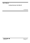
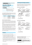
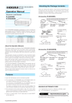
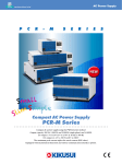
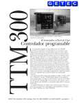
1
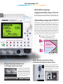
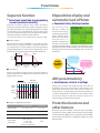
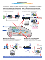
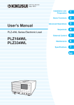
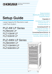
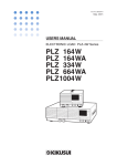
Internet
Electronic Load
http://www.kikusui.co.jp/
P L Z - 4 W H
S E R I E S
NEW
Multi-functional Electronic Load
PLZ-4WH Series
Maximum operating voltage: 650V
165W, 330W, 1000W: 3 types
With connecting boosters (1000W type exclusive), maximum of 9kW/450A
Operating mode for constant current, constant resistance, constant voltage, constant power,
constant current + constant voltage, and constant resistance + constant voltage
Sequence function (up to 1024 steps)
Voltage monitor terminal for monitoring high voltage
Equipped as standard with USB 2.0, GPIB, and RS-232C
650V
All new design with upgraded performance !
High-Voltage Electronic Load
For EV and HEV high-voltage converters.
With the booster, extended capacity at
a low cost can be realized!
In recent years, the market trend of various devices
that compose in the automotive electronics such as
EV, HEV, and the new energy market for PV power
generation, fuel cells, secondary batteries have been
moved to higher voltage and larger capacities. At
the same time, it has increased the demand for the
Electronic Load evaluation equipment to meet these
new requirement. The PLZ-4WH Series continues
to provide excellent operability of the conventional
model (PLZ-4W Series) while extending the
maximum operating voltage to 650V. Furthermore,
when a booster unit (PLZ2004WHB) is connected,
up to 9kW/450A can be realized with less space
and at a low cost. The interface, USB, GPIB, and RS232C functions comes as standard and supports
automated testing applications.
EV and HEV high-voltage converter evaluation testing
PV power generation, fuel cell, secondary batteries,
Applications
and other evaluation testing High-voltage device
evaluation testing
Actual
size
D C
E L E C T R O N I C
L O A D
NEW
Multi-functional Electronic Load
PLZ-4WHSeries
4 model
■ Product line-up
Model
Operating voltage
Current
Power
PLZ164WH
8.25A
165W
PLZ334WH
16.5A
330W
PLZ1004WH
PLZ2004WHB
5V ċ 650V
50A
1000W
100A
2000W
[Other features]
● Parallel operation function ● Communication function ● Voltage monitor output ● Current monitor output ● Adjustable slew rate ● Switching operation ● Soft start ● Elapsed time display
● Auto load-off timer ● Remote sensing ● External load on/off control input ● External range switching input ● External trigger input ● External alarm input ● Alarm status output
● Load-on status output ● Range status output ● Short signal ● External voltage control (CC, CR, CV, and CP modes) ● External resistance control (CC, CR, CV, and CP modes)
● Overvoltage protection (OVP) ● Overcurrent protection (OCP) ● Overpower protection (OPP) ● Overheat protection (OHP) ● Undervoltage protection (UVP) ● Reverse connection protection (REV)
2
Accessibility
Reliable testing
supported by ease of use
The front panel is the common design in all of PLZ-4W Series.
Since operability is uniform, tests can be set up quickly and easily.
Operating range up to 650 V
The PLZ-4WH supports input voltages of up to 650V, and it
can be used to evaluate EV and HEV in-vehicle chargers, DC/
DC converters, and battery cells; evaluate power supplies
for high-voltage DC electric supply systems; perform PFC
tests on European and other three-phase 400V system
input power supplies; and evaluate and test high-voltage
parts related to such equipment. Moreover, it achieves to
enlarge further operating range. (See the figure below.) It
can operate from 5V, and even if the current is more than 0.5V
and less than 5V, it can be used with reduced current.
● Comparison with our conventional
PLZ-3WH (PLZ1003WH) model
Operating range of Model PLZ1004WH (H range)
4WH
650
3WH
500
Conventional Model
PLZ1003WH
1
kW
100
Operating area
where specifications
are guaranteed
Input
voltage (V)
10
5
Actual operating area
3WH
1.0
4WH
0.5
50A
0.1
0.1
Easy measurement of
voltage and current
In addition to an insulated-type
current monitor terminal, an
insulated-type voltage monitor
terminal has been attached to the
front panel. This makes it possible
to measure voltage and current
simply and with confidence.
When set in 650V range
When set in 65V range
1.54
1
10
Input current (A)
50
100
Full-featured interface
communication function
The unit comes equipped as
standard with USB, GPIB, and RS232C functions, so it can easily
be incorporated into a variety of
inspection systems.
100:1
10:1
3
Performance
Achieving up to 9kW/450A with less space and low cost
By connecting the maximum of four PLZ2004WHB boosters (sold separately)
to the PLZ1004WH, it is possible to use the product as an Electronic Load unit
for up to 9kW/450A. Compared to parallel operation of the same model, size
(space) reductions of up to about 30%, can be achieved. Incidentally, optional
PC01-PLZ-4W and PC02-PLZ-4W parallel operation cables will be required for
connections depend on the number of units to be connected.
■
● In comparison of the conventional model
for the maximum 9kW system
boosters PLZ2004WHB
Approx.
30%
of reduced
volume
*Exclusively used for Model PLZ1004WH.
It can not be used to connect any other model.
● Example combination
3 kW system consisting of PLZ1004WH (top)
and PLZ2004WHB booster (bottom)
Conventional Model
PLZ-3WH Series
PLZ1003WH×9
NEW
PLZ-4WH Series
PLZ1004WH + PLZ2004WHB×4
● Parallel operating units and capacity (maximum current and power)
Slave Unit
PLZ2004WHB
1 Unit
2 Units
3 Units
4 Units
150A
3000W
250A
5000W
350A
7000W
450A
9000W
Capable of parallel operation with
up to five units of the same model
Parallel operation without the use of boosters is also possible up
to five units of the same model, including the master unit, can be
connected in parallel (5kW/250A maximum). In this case, the system
operates under the master-slave configuration, and the master unit
controls and displays the entire system. Note that optional PC01PLZ-4W parallel operation cables will be required for connections
depend on the number of units to be connected.
● Basic connection diagram
[Booster operation]
[Parallel operation]
Master (PLZ1004WH)
Master (PLZ1004WH)
Booster (PLZ2004WHB)
Slave (PLZ1004WH)
Slave (PLZ1004WH)
Booster (PLZ2004WHB)
Slave (PLZ1004WH)
● Parallel operating units and capacity (maximum current and power)
Slave Unit
1 Unit
2 Units
3 Units
4 Units
PLZ164WH
16.5A
330W
24.75A
495W
33A
660W
41.25A
825W
PLZ334WH
33A
660W
49.5A
990W
66A
1320W
82.5A
1650W
PLZ1004WH
100A
2000W
150A
3000W
200A
4000W
250A
5000W
Booster (PLZ2004WHB)
Slave (PLZ1004WH)
Booster (PLZ2004WHB)
ーPC02-PLZ-4W parallel cable
*The constant current mode setting accuracy and current measurement accuracy can be set
to the same accuracy as that of the main unit by calibrating in parallel operation.
ーPC01-PLZ-4W parallel cable
(for connecting main unit and booster)
★ Large capacity systems (9kW and above), rack systems and so on is also able to be supported. For details, please contact us.
4
Performance
Low range (1/100) feature
In CC, CR, and CP modes, three ranges are available: H, M, and L.
The L range is 1/100, enabling coverage from low to high power
with a single unit.
● Current setting resolution
PLZ164WH
PLZ334WH
PLZ1004WH
H
300µA
1mA
2mA
M
30µA
100µA
200µA
L
3µA
10µA
20µA
Ability to switch between a wide range of response speeds
The PLZ-4WH detects input current and voltage, and it operates
by negative feedback control of those values. It secures and
maintains stable operation by enabling the user to select the
optimum speed of response by setting the negative feedback
control response as shown below to counter operational
instability that occurs in connection with the response
characteristics of the test object, length of the load wiring, or size
of the loop, for instance.
CC, CR modes (4 stages)
CV mode (5 stages)
1/1:
Normal response speed
100:
100 times the normal speed
1/2:
Half the normal speed
10:
10 times the normal speed
1/5:
One-fifth the normal speed
1/1:
Normal response speed
1/10:
One-tenth the normal speed
1/10:
One-tenth the normal speed
1/100: One-hundredth the normal speed
Support for six operation modes
The PLZ-4WH is equipped with six operation modes: constant current, constant resistance, constant voltage, constant power, constant
current + constant voltage, and constant resistance + constant voltage modes.
Equivalent circuits and operation in each mode
●Constant power mode(CP)
●Constant current mode(CC)
I
V1
Constant Voltage
power supply
V
PLZ-4WH Series
Electronic Load
0
V1
Constant voltage
power supply
Voltage[V]
Voltage[V]
I
Current is constant
even when the voltage
changes
V
PLZ-4WH Series
Electronic Load
Current[ I]
V
PLZ-4WH Series
Electronic Load
V2
R=
V1
0
I1
V1
I1
= VI22
V M Battery
I2
Rated maximum
CC operation
Current is constant
even when the
voltage varies
CV
PLZ-4WH Series
Electronic Load
CV operation
Voltage is constant even
when the current varies
0 Current[ I]
CC setting value
●Constant resistance+constant voltage mode(CR+CV)
I
PLZ-4WH Series
Electronic Load
I1
Setting
value
V
Voltage is constant even
when the current varies
V
I
I2
Voltage[V]
V1
Constant voltage
power supply
R1
Current[ I]
●Constant voltage mode(CV)
R1
0
●Constant current+constant voltage mode(CC+CV)
0
R1
Voltage[V]
V1
Constant voltage
power supply
Voltage[V]
I
I2
V2
Voltage[V]
Resistance (V/I) is constant
even when the voltage and
current vary
P = V 1 I1 = V 2
V1
Current[ I]current value
CC setting value
●Constant resistance mode(CR)
Power (current×voltage) is constant
even when the current and voltage vary
I
VM
Battery
CV
V
Current[ I]
Setting
value
PLZ-4WH Series
Electronic Load
CR operation
Resistance (V/I) is constant
even when the voltage and
current vary
CV operation
Voltage is constant even
when the current varies
0 Current[ I]
5
Functions
Load-on/off operations
Soft start function
▶ Adopting
▶ Assures even with steep voltage application
With load-on/off operations, the following items can be selected
in addition to standard operations:
● Start-up with load-on status when the power is turned on
● Display the elapsed time of the load-on period
● Load-off after a certain time has elapsed
● Load-on/off by the relay or other external signal
In constant current mode, the product can prevent the generation
of overcurrent* even when voltage is steeply applied from the DUT
in "Load On condition and with the current having been set." For
example, in a battery discharge test, it can suppress the generation
of overcurrent when for
ON
Input voltage
some reason voltage is
Input current
suddenly applied to an
PLZ-4WH
Electronic Load used for
Series
0
discharge.
Time
Remote sensing function
*There is electrostatic capacitance
between the Electronic Load input
terminals. Charging and discharging current flows to this capacitance.
the Load-on/off functions that
flexibly apply to the system
ON
▶ Compensating
the voltage drop of the wiring
Connecting a sensing terminal to the DUT makes it possible to
set the combined resistance, including even the resistance of the
wiring, from the panel in constant resistance mode. Also, points
that connect the sensing function can be set to a certain power
and certain voltage in constant power mode and constant voltage
mode. Furthermore, since transient characteristics are improved in
these constant voltage, constant power, and constant resistance
modes, it also leads to operational stability. (Voltage that can be
compensated: 2V one way)
Switching function
▶
Transient response test conditions are
also freely changeable on the spot
In constant current mode and constant resistance mode, switching
operations of up to 4kHz are possible with the built-in oscillator.
Also, the level, frequency, duty cycle (ratio), and other configuration
parameters can be changed even during a load-on period.
FREQ
Th
TL
SET[A] (100 %)
LEVEL[A] (%)
0[A] (0 %)
【Configuration parameters】
■Operation modes: CC and CR
■Duty cycle settings: 5% to 95%, in 0.1% steps
■Frequency setting range: 1Hz to 4kHz
■Frequency setting resolution:
0.1Hz at 1Hz to 10Hz
1Hz at 10Hz to 100Hz
10Hz at 100Hz to 1kHz
100Hz at 1kHz to 4kHz
■Frequency setting accuracy: ±0.5% of set
*The minimum duration for a duty cycle is 50μs.
6
Edge where pulse is
output from Trig Out
terminal
▶ Ability
to start up the power in CC mode
In many cases during constant voltage power supply tests, testing
is conducted in constant
resistance mode for start-up
time measurements (during
Input
start-up), and in constant
current
current mode during load
change tests. If, however, the
Time
soft start time is set to a time
When soft start time is appropriate
corresponding to the start-up
Start-up time of equipment being tested
time of the constant voltage
Start-up time of this product
power supply, it is possible to
perform start-up time measurements and load change tests in constant
current mode, without changing the operation mode. (Either 1, 2, 5, 10,
20, 50, 100, or 200ms can be selected as the soft start time.)
Short function
▶ Improved
efficiency for the current
limit evaluation with a single action
In tests such as the DC power supply "fold-back type drooping
characteristics test of current limiting characteristics," the
maximum current (in constant current mode) or the minimum
resistance (in constant resistance mode) can be set with a single
action and thus increase work efficiency. At the same time, since
contact signals are output to an EXT CONT connector, it is possible
to achieve even lower impedance shorting by driving exterior
relays and shorting the output of the tested device.
EUT
Large
current relay
+
+
−
−
PLZ-4WH
Series
Drive
circuit
Rear panel
EXT CONTconnector
Functions
Sequence function
▶ Actual
load simulation by programming
current waveforms internally
Arbitrarily set sequence patterns can be saved in the built-in
memory and executed. Ten normal sequence programs and one
fast sequence program can be saved. Although sequence editing
and execution can be performed from the panel, those tasks
can also be performed easily by using the application software
separately sold "Wavy"* sequence creation software.
*A personal computer will require one of the following interfaces: USB, RS232C, or GPIB.
■ Normal sequence
The execution time and Load ON/OFF can be set for each step.
The level can be changed not only in a stepped form but also
in a ramped form. It is also possible to cancel pausing both by
using the PAUSE function and by external trigger input, and to
synchronize with trigger output and other external equipment.
Step 1
7A
Step 2
Elapsed time display and
automatic load-off timer
▶ Convenient
battery discharge function
By combining four
functions, namely, the
elapsed time display,
undervoltage protection
(UVP), load-off voltage
display, and automatic
l o a d - o f f t i m e r, i t i s
possible to perform two
▲ Example of load-off voltage display
tests that are convenient
for battery discharge testing, namely, the "measurement of time
from discharge start to the final voltage" and "measurement from
discharge start to the closed circuit voltage after a certain time
has elapsed."
Step 3
Input
current
Voltage
100 sec ramp
(RAMP ON)
7A
150 sec ramp
(RAMP OFF)
7A
Time
80 sec ramp
(RAMP ON)
0.5A
V2
■ Fast sequence
Execution (RUN)
0
Tcutoff
Tcount Time
ABC preset memory
TIME BASE
(execution interval)
▶ Instantaneous
Trigger
output
retrieval of settings
Settings can be saved in three memories (A, B, and C) that are
available for each range of each mode. Saved settings can be
freely retrieved and saved even during load-on periods. In
constant current + constant voltage mode and constant resistance
+ constant voltage mode, the memories for the constant current
and constant voltage, and for the constant resistance and
constant voltage, can be retrieved and saved.
10A
Input
current
5A
STEP 1 2 3 4 5 6 7 8 9 10
● Sequence configuration parameters
Normal Sequence
Fast Sequence
Operation mode
CC、CR、CV、CP
CC、CR
Maximum steps
256
1024
1ms∼999h59min
100 µs∼100ms
1ms(1ms∼1min)
100ms(1min∼1h)
1s(1h∼10h)
10s(10h∼100h)
1min(100h∼999h59min)
100 µs
Time resolution
(setting range)
Set the UVP detection
voltage (V1), and display
time (Tcount) that elapsed
before that voltage was
reached.(Tcount)
V1
Each step is executed at high speed. Since the time resolution is
high, fast simulation is possible. The execution time, level, and
trigger output can be set.
Step execution time
Convenient
for evaluating
batteries!!
Set the automatic load-off
timer (Tcutoff), and display
voltage (V2) after the
preset time has elapsed.
Protective functions and
other features
Overcurrent protection (OCP), overpower protection (OPP),
overvoltage protection (OVP), undervoltage protection (UVP),
overheat protection (OHP), reverse connection protection (REV),
external alarm input detection, configuration setting, and setup
memories (100)
7
Applications
Evaluation Test on EV/HEV internal chargers and DC/DC converters
Built-in charger characteristics test and battery simulation
●
By connecting a DC Electronic Load unit and high-voltage DC power
supply in parallel, the PLZ-4WH is used as a simulated battery
for an EV in-vehicle charger. Start-up tests and load change tests are
performed in Electronic Load CV mode.
●
Use as a high-speed constant-current power supply
The unit can be used as a high-speed constant-current power source
by controlling high-speed positive current at A and negative current at B.
A simulation of the regenerative current of brushless motor
with regards to the interactive converter is performed.
DC Electronic Load
PLZ-4WH Series
Constant
Current
Constant
Voltage
Constant
Current
Constant
Current
DC Electronic Load
PLZ-4WH Series
Constant
Voltage
A
ー
Constant
Current
+
V
Source
DC Electronic Load
PLZ-4WH Series
Built-in
charger
Wide Range DC Power Supply
PWR Series H type
DC-DC
converter
DC Electronic Load
PLZ-4WH Series
DC Power Supply
PAT-T Series
Sink
Constant
Current
+
ー
I
(Constant
Current )
Control PC
Wavy for PLZ 3ch
*custum order
A
0
Home charge plug
T (time)
Built-in charger
B
High-voltage battery(Li-ion)
New ECU
Quick charge plug
DC-DC
converter
Sub-battery
Rear drive
motor
●
EPS
ECU
DC/3-phase
converter(ECU)
Front drive
motor
▲ General view of EV interior
For power supply variation tests
●
Constant
Current
For motor surge absorption measurement
During a brushless motor performance evaluation,
the regenerative current from the brushless motor is absorbed,
protecting the power supply and ECU.
By connecting a DC Electronic Load unit and high-voltage DC power
supply in parallel, the PLZ-4WH is used as a simulated battery to
simulate medium speed power supply variations.Variation waveforms
can be created and executed with Wavy sequence creation software.
I (Constant Current)
Constant
Voltage
Constant
Voltage
Constant
Voltage
T (time)
*Regenerative current from motor
V
DC-DC
converter
Wide Range DC Power Supply
PWR Series H typeW
ECU
DC Electronic Load
PLZ-4WH Series
DC Power Supply
PAT-T Series
M
*Current flows both ways.
Brushless
motor
V
(Constant
Voltage )
Constant
Voltage
T (time)
DC Electronic Load Constant
Current
PLZ-4WH Series
*Absorbs regenerative current.
Control PC
Wavy for PLZ
★ Select a PLZ-4W, 4WL, or 4WA Series unit according to the purpose of use. See the series lineup at the end of this catalogue.
8
Applications
For evaluation test on parts
●For life performance acceleration tests
●As high-accuracy constant current power supply
The PLZ-4WH can be used not only for temperature rise tests,
long-term durability tests, pulse interrupt characteristics tests,
and other high-accuracy constant current tests but also
for pulse current evaluations.
By connecting a constant voltage power supply and a DC
Electronic Load unit in series, the product achieves constant
current at the DC Electronic Load unit's constant current accuracy.
Constant
Voltage
Constant
Voltage
Constant Constant
Current Resistance
I
DC Electronic Load
PLZ-4WH Series
DUT
DUT fuse/other
(Constant
Current )
I (Constant Current)
V
V
Pulse current
ー
+
V
DC Power Supply
PAT-T Series
(Constant
Voltage )
DC Electronic Load
PLZ-4WH Series
DC Power Supply
PAT-T Series
T (time)
Current sensor
For evaluation test on secondary batteries
●For battery charge-discharge tests
●Battery capacitor
The PLZ-4WH can be used to evaluate impedance and residual capacity
by discharging electricity not only at a normal constant current
but also at a pulse current corresponding to the actual load.
Waveform patterns can be created with Wavy for PLZ, too.
During a secondary cell performance evaluation, it is necessary
to perform a capacity test based on the battery's rating. Using
the Electronic Load unit's +CV function, a capacity evaluation is
performed by discharging the CV when the prescribed voltage is reached.
Wide Range DC Power Supply
PWR Series H type
DC Electronic Load
PLZ-4WH Series
Constant
Current
Constant
I Current )
(
Secondary
battery
Constant
Voltage
Constant
Current
+
+
+
V
(Constant
Voltage )
CC
setting
ー
Pulse discharge
voltage and current
Option
"Wavy" sequence creation and control software
Wavy series
CC operation CV operation
V
ー
Battery
Capacitor
V
+CV
setting
(Constant
Voltage )
(Constant
Voltage )
I
(Constant
Current )
DC Electronic Load
PLZ-4WH Series
CC setting
Interrupting current at CV setting
Download !
A Wavy trial version is available!
You can try it out for three weeks without functional limitations.
http://www.kikusui.co.jp/download/index_ j.html
This is software that further enhances the waveform generation and sequence functions of the PLZ-4WH Series.
Using a mouse, it is possible to create and edit with the sensation of using a spreadsheet and drawing.
■ Sequence creation software Wavy for PLZ-4W
Operating environment : Windows 2000 / Windows XP / Windows Vista / Windows 7
*See our home page for details.
▲ Screen sample
● Creating and editing data of test conditions required so that the sequence operation can be done easily.
● Using the save function for data files of test conditions makes routine test condition control easy.
● The progress of executed sequences is displayed by the cursor and settings on an “execution graph.”
● It is possible to observe actual output intuitively, using a “monitor graph” that plots
monitored values while an execution is in progress.
● Acquired monitor data can be saved as test results.
● A “waveform image” window was newly added, making it easy to see the waveforms
of alternating current (AC) signals.
● Arbitrary new waveforms can be easily created and edited. Also, arbitrary waveforms
that are created can be quickly written and output.
● The product supports the selection and nonselection of sequence step items. Functions
such as the pause function, trigger function, and AC waveform can be selected as needed.
9
■ PLZ164WH /
PLZ334WH / PLZ1004WH specifications
Model
Ratings
Model
PLZ164WH
PLZ334WH
Operating voltage
H range
L range
5V to 65V
Setting
range
H range
0V to 682.5V
L range
0V to 68.25V
H range
20mV
Current
8.25A
16.5A
50A
Power
165W
330W
1000W
Resolution
0.5V
Load-off input resistance
2.21
[MΩ]
*2
Constant Current (CC) mode
Model
Operating range
Setting range
Resolution
Parallel operation (typ)
PLZ1004WH
0 to 50A
M range
0 to 825mA
0 to 1.65A
0 to 5A
L range
0 to 82.5mA
0 to 165mA
0 to 500mA
H range
0 to 8.6625A
0 to 17.325A
0 to 52.5A
M range
M range
0 to 866.25mA
0 to 1.7325A
0 to 5.25A
L range
L range
0 to 86.625mA
0 to 173.25mA
0 to 525mA
H range
0W to 173.25W
H range
300μA
1mA
2mA
M range
30μA
100μA
200μA
L range
3μA
10μA
20μA
Constant Power (CP) mode
Model
H range
Operating
range
0W to 105W
0W to 10.5W
H range
10mW
20mW
100mW
Resolution
M range
1mW
2mW
10mW
0.1mW
0.2mW
1mW
Setting
accuracy
L range
4mA
12mA
Setting
range
p-p*5
20mA
40mA
120mA
Setting
accuracy*2
*1
*2
*3
*4
*5
±(3 % of f.s)
±(3 % of f.s + Vin*2/2.21[MΩ])
Model
PLZ334WH
PLZ1004WH
1.65S to 30μS
3.3S to 60μS
10S to 200μS
330mS to 6μS
1S to 20μS
(1Ω to 49.999kΩ)
33mS to 0.6μS
100mS to 2μS
(60.606Ω to 3.333MΩ) (30.303Ω to 1.666MΩ)
(10Ω to 500kΩ)
1.7325S to 0 S
3.465S to 0 S
10.5S to 0 S
(577.2mΩ to OPEN)
(288.6mS to OPEN)
(95.23mΩ to OPEN)
173.25mS to 0 S
346.5mS to 0 S
1.05S to 0 S
(5.772Ω to OPEN)
(2.886Ω to OPEN)
(952.3mΩ to OPEN)
±(5 % of f.s*1)
(at 23℃±5℃)
PLZ164WH
PLZ334WH
H range
Display
PLZ1004WH
0.00V to 650..00V
L range
0.000V to 65.000V
Accuracy
±(0.1 % of rdng + 0.1 % of f.s)
Parallel operation(TYP)
Ammeter
Model
PLZ164WH
(6.06Ω to 333.333kΩ) (3.03Ω to 166.666kΩ)
H, M range
Display
L range
Accuracy
PLZ164WH
PLZ334WH
PLZ1004WH
0.0000A to 8.2500A
0.000A to 16.500A
0.00A to 50.000A
0.000mA to 82.500mA 0.00mA to 165.00mA 0.00 mA to 500.00mA
H, M, L range
±
(0.2 % of rdng + 0.3 % of f.s*1)
Parallel operation
±
(1.2 % of rdng + 1.1 % of f.s*1)
*1 When M range: Full scale of H range
Wattmeter
Model
Display
*1
H, M range
PLZ164WH
PLZ334WH
PLZ1004WH
0.00W to 165.00W
0.00W to 330.00W
0.0W to 1000.0W
0.00W to 107.25W
L Other than CP mode 0.000W to 53.625W
range
CP mode
0.0000W to 1.6500W 0.0000W to 3.3000W
0.0W to 325.00W
0.000W to 10.000W
*1 Displays the product of the voltage and current display values
17.325mS to 0 S
34.65mS to 0 S
105mS to 0 S
(57.72Ω to OPEN)
(28.86Ω to OPEN)
(9.523Ω to OPEN)
H range
30μS
60μS
200μS
Model
M range
3μS
6μS
20μS
Operating mode
CC and CR
L range
0.3μS
0.6μS
2μS
Duty cycle settings
5 % to 95 %※1 0.1% steps
Frequency setting range
1Hz to 4kHz
L range
Resolution
At least 0.25W
Less than 0.25W
Voltmeter
(606.06mΩ to 33.333kΩ)(303.03mΩ to 16.666kΩ) (100mΩ to 5kΩ)
M range
±
(3 % of f.s*1)
*1 When M range: Full scale of H range
*2 Vin: Rear load input terminal voltage or sensing terminal voltage
Constant Resistance (CR) mode
H range
0W to 1050W
Parallel operation
(TYP)
2mA
When doing parallel operation with same model: Single
Parallel
unit specifications x Number of units. When doing
operation
parallel operation with PLZ2004WHB: PLZ1004WH
(typ)
p-p*5
single unit specifications x (Total power capacity/kW)
Full scale of range, with M range being full scale of H range
Vin: The voltage at the load input or sensing terminals
When the input voltage is changed from 5V to 650V at a current equal to the rated power/650V
Measurement frequency bandwidth: 10Hz to 1MHz
Measurement frequency bandwidth: 10Hz to 20MHz
L range
1W to 10W
0W to 346.5W
0W to 34.65W
2mA
rms*4
16.5mS to 0.3μS
10W to 100W
0W to 3.465W
H, M range
165mS to 3μS
3.3W to 33W
0.33W to 3.3W
0W to 17.325W
±(0.2 % of set + 0.1 % of f.s)+ Vin*2/2.21[MΩ]
rms*4
M range
1.65W to 16.5W
0.165W to 1.65W
0W to 1.7325W
Less than 300μA
L range
PLZ1004WH
100W to 1000W
L range
L range
20mA
PLZ334WH
33W to 330W
M range
±(0.2 % of set + 0.1 % of f.s)
±
(1.2 % of set + 1.1 % of f.s*1)
PLZ164WH
16.5W to 165W
Setting
range
At least 300μA
Ripple
Operating
range*1
65mV
*1 At sensing terminal during remote sensing when input voltage is within operating range. Same with parallel operation, too.
*2 With respect to change in current at 10% to 100% of rated voltage with input voltage of 5V (during remote sensing).
0 to 16.5A
H, M range
H range
±
(0.2 % of set + 0.2 % of f.s)
Input current fluctuation*2
PLZ334WH
Parallel operation
Model
2mV
±(0.2 % of set + 0.2 % of f.s)
Setting accuracy*1
0 to 8.25A
L range
Input voltage
variation*3
L range
PLZ164WH
±
(0.2 % of set + 0.1 % of f.s*1)
PLZ1004WH
5V to 650V
H range
H, M range
Setting
accuracy
PLZ334WH
Operating
range
5V to 650V
Minimum operating voltage*1
PLZ164WH
PLZ1004WH
*1 Minimum voltage when current starts to flow through the unit. Occurs at the load input terminal.
*2 When doing parallel operation with same model: 2.21/number of units [MΩ]. When doing
parallel operation with PLZ2004WHB: 2.21 [MΩ].
*1
*2
*3
*4
*5
Constant Voltage (CV) mode
H, M range
±
(0.5 % of set*3 + 0.5 % of f.s*4)
L range
±(0.5 % of set*3 +0.5 % of f.s)+ Vin*5/2.21[MΩ]
Parallel
operation
(typ)
±(1.2 % of set +1.1 % of f.s*4)
Conductance [S] = Input current [A] / Input voltage [V] = 1 / Resistance [Ω]
Converted value with input current; at sensing terminal
set=Vin/Rset
When M range: Full scale of H range
Vin: Rear load input terminal voltage or sensing terminal voltage
Switching mode
1Hz ∼ 10Hz
Frequency
setting
resolution
PLZ164WH
PLZ334WH
0.1Hz
10Hz ∼ 100Hz
1Hz
100Hz ∼ 1kHz
10Hz
1kHz ∼ 4kHz
Frequency setting accuracy
PLZ1004WH
100Hz
±
(0.5 % of set)
*1 The minimum time duration is 50μs. From 1 to 4kHz, the maximum duty cycle is limited by it.
Slew rate
Model
PLZ164WH
PLZ334WH
PLZ1004WH
0.132mA/μs to 0.132A/μs
0.264mA/μs to 0.264A/μs
0.8mA/μs to 0.8A/μs
M range
13.2μA/μs to 13.2mA/μs
26.4μA/μs to 26.4mA/μs
80μA/μs to 80mA/μs
L range
1.32μA/μs to 1.32mA/μs
2.64μA/μs to 2.64mA/μs
8μA/μs to 8mA/μs
50μA
(13.2 to 132
[mA/μs]
)
100μA(26.4 to 264
[mA/μs])
300μA
(80 to 800
[mA/μs])
30μA(8 to 80
[mA/μs])
H range
Setting range*1
H range
Resolution
(Setting range)
M range
L range
Setting accuracy*2
5μA(1.32 to 13.2
[mA/μs]
)
10μA(2.64 to 26.4
[mA/μs])
0.5μA
(0.132 to 1.32
[mA/μs]
)
1μA
(0.264 to 2.64
[mA/μs])
3μA
(0.8 to 8
[mA/μs])
5μA
(1.32 to 13.2
[mA/μs]
)
10μA(2.64 to 26.4
[mA/μs])
30μA(8 to 80
[mA/μs])
0.5μA
(0.132 to 1.32
[mA/μs]
)
1μA
(0.264 to 2.64
[mA/μs])
3μA
(0.8 to 8
[mA/μs])
0.05μA
(13.2 to 132
[μA/μs])
0.1μA
(26.4 to 264
[μA/μs])
0.3μA(80 to 800
[μA/μs])
0.5μA
(0.132 to 1.32
[mA/μs]
)
1μA
(0.264 to 2.64
[mA/μs])
3μA
(0.8 to 8
[mA/μs])
0.05μA
(13.2 to 132
[μA/μs])
0.1μA
(26.4 to 264
[μA/μs])
0.3μA(80 to 800
[μA/μs])
0.005μA
(1.32 to 13.2
[μA/μs]
)
0.01μA
(2.64 to 26.4
[μA/μs])
0.03μA
(8 to 80
[μA/μs])
±(10 % of set + 25μs)
*1 In constant current mode. In constant resistance mode, the maximum slew rate in each range is 1/10.
*2 Time to reach 10% to 90% with respect to a 2% to 100% (or for M range a 20% to 100%) change from the rated current.
10
Soft start
Model
PLZ164WH
PLZ334WH
Operating mode
CC mode
Time setting range*1
1,2,5,10,20,50,100,200ms
Time setting accuracy
±(30 % of set + 100μs)
PLZ1004WH
*1 Time for input current to reach 10% to 90%
Response
Response speed
CC/CR mode
Switchable in 4 stages(1/1、1/2、1/5、1/10)
CV mode
Switchable in 5 stages(100、10、1、1/10、1/100)
One way
2V
Remote sensing
Voltage that can be compensated
Protective functions
Overvoltage protection (OVP)
110% of rated voltage for the range
Overcurrent protection (OCP)
110% of 0.01 A rated current or 110% of the maximum current for each range: Load-off or limit selectable
Overpower protection (OPP)
From 0.1% to 110% of rated power or 110% of the maximum power of each range: Load-off or limit selectable
Overheat protection (OHP)
Load-off when heat sink temperature reaches 90°
C
Undervoltage detection (UVP)
Can set to Off, 5V to 650V
Reverse connection protection (REV)
By fuse. Load-off when ALM occurs.
Sequence functions
Operating modes
Normal
sequence
Fast
sequence
CC,CR,CV,CP
Maximum steps
256
Step execution time
1ms - 999h59min
Time resolution (setting range)
1ms
(1ms to 1min)
、100ms(1min to 1h)
、1s(1h to 10h)
、10s(10h to 100h)
、1min
(100h to 999h59min)
Operating mode
CC,CR
Maximum steps
1024
Step execution time
100μs to 100ms
Time resolution
100μs
Other
Elapsed time display
Measurement of time from load-on to load-off, On/Off capable 1 s to 999 h 59 min 59 s
Auto load-off timer
Automatic load-off after elapse of preset time. Can set from 1 s to 999 h 59 min 59 s or to Off.
Analog external control (EXT CONT connector)
Load-on/off control input
Switchable logic level, pull-up to 5V at 10kΩ (CMOS level signal)
External range switching input*1
2 bit, pull-up to 5V at 10kΩ (CMOS level signal)
Trigger input
Clear the sequence operation pause when at least 10μs are input for H (CMOS level signal for 5V system), pull-down to common by 100kΩ resister
External alarm input
Alarm operation with L, pull-up to 5V at 10kΩ (CMOS level signal)
Alarm status output
During alarm (OVP, OCP, OPP, OHP, REV) operation and external alarm input: On, open collector (photocoupler)*2
Load-on status output
During load-on: On, open collector (photocoupler)*2
Range status output
2 bit, open collector (photocoupler)*2
Short signal
Relay contact output (30Vdc/1 A)
External voltage control input
(CC, CR, CV, CP modes)
CC, CR, CV, and CP modes. 0 to 100% of rated current, voltage, and power at 0 to 10V (CC, CV, CP).
Maximum to minimum resistance at 0 to 10V (CR).
External resistance control input
(CC, CR, CV, CP modes)
0 to 100% or 100 to 0% of rated current, voltage, and power at 0 to 10kΩ (CC, CV, CP).
Maximum to minimum resistance or minimum to maximum resistance at 0 to 10kΩ (CR).
External CV voltage control input
0 to 10% of rated voltage at 0 to 10V
Current monitor output
10V f.s. (H/L range), 1V f.s. (M range), output impedance of 1kΩ
Voltage monitor output
10V for each range f.s., output impedance of 1kΩ
Front BNC terminal
Trigger output
Output of pulse during sequence operation, switching operation, or GPIB GET command input
Current monitor output
10V for full scale (H/L range), 1V for full scale (M range)
Voltage monitor output
6.5V for full scale in each range
Communication functions
GPIB
IEEE std. 488.1-1987 SH1, AH1, T6, L4, SR1, RL1, PP0, DC1, DT1, C0,E1 Supports SCPI and IEEE std. 488.2-1992 specification command set.
RS232C
D-SUB 9pin(EIA-232-D)
Baud rate: 2400/4800/9600/19200 bps; Data bit: 8; Stop bit: 1/2; Parity: none;
Flow control: Xon/Xoff. Supports SCPI and IEEE std. 488.2-1992 specification command set.
USB
USB 2.0, 12 Mbps. Conforms to USBTMC-USB488 device class.
*1 Front panel settings are only effective in the H range. *2 Photocoupler's maximum applied voltage is 30V and maximum current is 8mA.
*3 External CV voltage control input cannot be used in CP or CV mode.
General specifications
Model
PLZ164WH
PLZ334WH
Input voltage range / input frequency range
Power consumption
80VAmax
90VAmax
Inrush current*1
Protective conductor current (when at 100V, 50Hz: typical value)
600μA
0°to 40°
C, 20% to 85% rh (no condensation)
Storage temperature range/humidity range
-20°to 70°
C, 90% rh or less (no condensation)
Ground voltage
Withstand
voltage
±750Vdc
Primary to input terminal
1000Vdc, 30MΩ or more (ambient temperature with 70% rh or less)
Primary to chassis
1000Vdc, 30MΩ or more (ambient temperature with 70% rh or less)
Input terminal to chassis
1000Vdc, 30MΩ or more (ambient temperature with 70% rh or less)
Primary to input terminal
1500V Vac no abnormality for one minute
Primary to chassis
1500V Vac no abnormality for one minute
Input terminal to chassis
1000V Vdc no abnormality for one minute
Dimensions (mm)
Weight
Battery backup
160VAmax
140Amax
Operating temperature range/humidity range
Insulation
resistance
PLZ1004WH
100 to 240Vac (90 to 250Vac) single phase, continuous: 47-63Hz
See the outline drawing.
Approx. 7 kg (15.4 lb.)
Approx. 8kg (17.6 lb.)
Approx. 16kg (35.3 lb.)
Backs up configuration (setting) information
Accessories
Power cord (2.4m length with SVT3 18AWG 3P plug) : 1pc., Load input terminal cover : 1pc., Lock plates for load input terminal cover : 2pc.,
Screw sets for load input terminal : 2pc., CD-R*2 : 1pc., Setup guide (Japanese/English) : 1pc., Quick reference in Japanese : 1pc., Quick reference in English : 1pc.
Electromagnetic ompatibility*3
Compatibility with these standards: Immunity IEC61326-1:2006 Class A Emission IEC61326-1:2006 Class A IEC61000-3-2:2006+A1:2009+A1:2009 IEC61000-3-3:2008
Safety*4
Compatibility with these standards: Low Voltage Directive 2006/95/EC EN61010-1:2001
*1 Approximately 70A with 100Vac input *2 CD-R contains application and sample, user's manual, communication interface manual, and VISA library (KI-VISA).
*3 Applies only to models that display CE marking on panel. Does not apply to specially ordered or modified items.
*4 This product is a Class 1 instrument. Be sure to ground this product's protective conductor terminal. If it is not properly grounded, safety cannot be guaranteed.
11
■ PLZ2004WHB specifications
Ratings
General specifications
Model
PLZ2004WHB
Model
PLZ2004WHB
Operating voltage
5V to 650V
Input voltage range
100Vac to 240Vac(90Vac to 250Vac)single phase, continuous
Current
100A
Input frequency range
47Hz to 63Hz
Power
2000W
Power consumption
200VAmax
Minimum operating voltage*1
0.5V
Inrush current*1
120Amax
Input resistance when load-off
2.21
[MΩ]*2
Protective conductor current
600μA (typical: 100V, 50Hz)
*1 Minimum voltage when current starts to flow to the unit. Occurs at the load input terminal.
*2 In a condition in which the master unit (PLZ1004WH) is connected.
Operating temperature range
0℃ to 40℃
Operating humidity range
20% to 85% rh (no condensation)
Constant Current (CC) mode
Operating range
Setting range
Storage temperature range
-20℃ to 70℃
H range
0 to 100A
Storage humidity range
90% rh or less (no condensation)
M range
0 to 10A
Ground voltage
±750Vdc
L range
0 to 1A
H range
0 to 105A
M range
0 to 10.5A
L range
0 to 1.05A
H range
10mA
Resolution*1
M range
1mA
L range
0.1mA
Setting accuracy*2
H,M,L range
±
(1.2 % of set + 1.1 % of f.s*3)
Ripple*2
H,M,L range
PLZ1004WH unit specifications ×
(Total power capacity/kW) (typ)
Insulation
resistance
Withstand
voltage
Accessories
Constant resistance (CR), constant voltage (CV), and constant power (CP) mode setting accuracy
CR mode
H,M,L range
±
(1.2 % of set + 1.1 % of f.s*1)
(TYP)
H,L range
±
(0.2 % of set + 0.2 % of f.s)
(TYP)
CP mode
H,M,L range
±
(5 % of f.s*1)23℃±5℃
(TYP)
Measurement functions
Voltmeter
Ammeter
Accuracy
H,L range
±
(0.1 % of rdng + 0.1 % of f.s)
(TYP)
H,M,L range
(TYP)
±
(1.2 % of rdng + 1.1 % of f.s*1)
Primary to chassis
1000Vdc, 30 MΩ or more (ambient temperature with 70% rh or less)
Input terminal to chassis 1000Vdc, 30 MΩ or more (ambient temperature with 70% rh or less)
Primary to input terminal
1500V Vac, no abnormality for one minute
Primary to chassis
1500V Vac, no abnormality for one minute
Input terminal to chassis
1000V Vdc, no abnormality for one minute
Dimensions (mm) / weight
*1 When one PLZ2004WHB unit is connected
*2 When connected to master unit
*3 Full scale of range, with M range being full scale of H range
CV mode
Primary to input terminal 1000Vdc, 30 MΩ or more (ambient temperature with 70% rh or less)
See the outline drawing. /Approx. 24kg (52.91 lb.)
One power cord (2.4m length with SVT3 18AWG 3P plug), one load input
terminal cover, two lock plates for load input terminal cover, two screw sets for
load input terminal, and one instruction manual
Compatibility with these standards:
Immunity IEC61326-1:2006 Class A
Electromagnetic
compatibility*2 Emission IEC61326-1:2006 Class A IEC61000-3-2:2006+A1:2009+A1:2009 IEC61000-3-3:2008
Safety*3
Compatibility with these standards: Low Voltage Directive 2006/95/EC EN61010-1:2001
*1 Approximately 60A with 100Vac input
*2 Applies only to models that display CE marking on panel. Does not apply to specially ordered
or modified items.
*3 This product is a Class 1 instrument. Be sure to ground this product's protective conductor
terminal. If it is not properly grounded, safety cannot be guaranteed.
Displays the product of the values indicated
by the voltmeter and ammeter
Wattmeter
*1 M range: full scale of H range
Protective functions *1
Overheat protection (OHP)
Load-off when heat sink temperature reaches 90°C
Load-off at time of detection
Reverse connection protection (REV)
Protection by fuse
*1 Other protective functions detect and operate with the PLZ1004WH.
■ Dimensions
■ Series Selection
unit:mm(inches)
●PLZ164WH, PLZ334WH (Type I)
214.5(8.44)
voltage
MAX470(18.50)
400(15.75)
MAX
30(1.18)
124(4.88)
MAX155(6.10)
650V
500V
NE W
650V
High Voltage
MAX
20(0.79)
Middle/Low Voltage
●PLZ1004WH (Type II)
12 8(5.04)
MAX150(5.91)
23(0.91)
27.9 70
30.1
(1.10) (2.76) (1.18)
MAX30
(1.18)
MAX455(17.91)
429.5(16.91)
MAX
10(0.39)
MAX470(18.50)
400(15.75)
367(14.45)
60V
30V
Low Voltage
PLZ-4WH
PLZ
4WH
PLZ-4W
5V
0V
●PLZ2004WHB
150V
1
150V
15 V
150V
1.5V
PLZ-4WA
0V
PLZ-4WL
30V
0.3V
MAX590(23.23)
550(21.65)
173(6.81)
MAX190(7.48)
430(16.93)
●Distributor/Representative
1-877-876-2807 www.kikusuiamerica.com
530 Lakeside Drive, Suite#180, Sunnyvale, CA 94085, U.S.A.
Phone : 408-733-3432 Facsimile : 408-733-1814
www.kikusui.cn
Room, D-01,11F, Majesty Bld, No.138, Pudong Ave, Shanghai City
Phone : 021-5887-9067 Facsimile : 021-5887-9069
■ All products contained in this catalogue are equipment and devices that are premised on use under the supervision of qualifi ed
personnel, and are not designed or produced for home-use or use by general consumers. ■ Specifi cations, design and so forth are
subject to change without prior notice to improve the quality. ■ Product names and prices are subject to change and production may be
discontinued when necessary. ■ Product names, company names and brand names contained in this catalogue represent the respective
registered trade name or trade mark. ■ Colors, textures and so forth of photographs shown in this catalogue may differ from actual
products due to a limited fi delity in printing. ■ Although every effort has been made to provide the information as accurate as possible
for this catalogue, certain details have unavoidably been omitted due to limitations in space. ■ If you fi nd any misprints or errors in this
catalogue, it would be appreciated if you would inform us. ■ Please contact our distributors to confirm specifications, price, accessories
or anything that may be unclear when placing an order or concluding a purchasing agreement.
Issue:Jun.2011 2011062KSOHEC11a