1
Instruction manual
Congratulations
Instruction manual
We congratulate you on your new Globecar motorhome and would like to thank you for choosing a quality
product from us.
Whatever journey you are planning - you will always have the perfect companion with a Globecar motorhome:
whether it is a city break, a short trip or a family holiday. The innovative and well-thought out floor plans offer
you a variety of options and the contemporary interior design in all our models gives off a homely atmosphere.
You will be amazed at the high standard of quality and all the variations available - space problems are a thing
of the past in our vehicles. Many practical details will prove extremely useful when on the road and will allow
you to relax even more on your holiday.
Each Globecar vehicle is manufactured with great care and the quality is closely checked. This ensures that
our products have a long service life.
This instruction manual primarily contains information on how to dismantle the living area of your motorhome.
It will give you all important information and tips so that you can enjoy all technical advantages of your
motorhome to the full. We have also included a chapter on maintenance - and thus on the conservation of
value.
In addition, you will find the documents on the base vehicle and the various built-in appliances.
For maintenance work or whenever you need some help, please always get in touch with your Globecar dealer.
They know your vehicle best of all, and will meet all your requests fast and reliably.
We wish you a lot of fun with your motorhome, a relaxing holiday and safe driving at all times.
© 2011 Pössl Freizeit und Sport GmbH, Ainring
Motorhome - 02/11-0 - GLO-MJ11-00EN
Instruction manual
Motorhome - 02/11-0 - GLO-MJ11-00EN
Contents
1
1.1
1.2
1.3
1.4
2
2.1
2.2
3
Records . . . . . . . . . . . . . . . . . . . . . . .
Vehicle document . . . . . . . . . . . . . . . . .
Warranty . . . . . . . . . . . . . . . . . . . . . . . .
Inspection records. . . . . . . . . . . . . . . . .
Inspection plan . . . . . . . . . . . . . . . . . . .
5
5
5
6
7
Introduction . . . . . . . . . . . . . . . . . . . 9
General . . . . . . . . . . . . . . . . . . . . . . . . 10
Environmental tips. . . . . . . . . . . . . . . . 10
3.1
3.1.1
3.1.2
3.1.3
3.2
3.3
3.4
3.5
3.5.1
3.5.2
3.6
3.7
Safety . . . . . . . . . . . . . . . . . . . . . . . .
Fire prevention . . . . . . . . . . . . . . . . . .
Avoidance of fire risks . . . . . . . . . . . . .
Fire-fighting . . . . . . . . . . . . . . . . . . . . .
In case of fire. . . . . . . . . . . . . . . . . . . .
General . . . . . . . . . . . . . . . . . . . . . . . .
Road safety . . . . . . . . . . . . . . . . . . . . .
Towing. . . . . . . . . . . . . . . . . . . . . . . . .
Gas system . . . . . . . . . . . . . . . . . . . . .
General information. . . . . . . . . . . . . . .
Gas bottles . . . . . . . . . . . . . . . . . . . . .
Electrical system . . . . . . . . . . . . . . . . .
Water system . . . . . . . . . . . . . . . . . . .
4
Before the journey . . . . . . . . . . . 19
4.1
4.1.1
4.1.2
4.1.3
4.2
4.2.1
4.3
4.4
Payload . . . . . . . . . . . . . . . . . . . . . . . .
Terms . . . . . . . . . . . . . . . . . . . . . . . . .
Calculating the payload. . . . . . . . . . . .
Loading the vehicle correctly. . . . . . . .
Entrance step . . . . . . . . . . . . . . . . . . .
Electrically operated entrance step . . .
Television . . . . . . . . . . . . . . . . . . . . . .
Road safety . . . . . . . . . . . . . . . . . . . . .
19
19
20
21
22
22
22
23
5
During the journey . . . . . . . . . . .
Driving the motorhome . . . . . . . . . . . .
Driving speed . . . . . . . . . . . . . . . . . . .
Seat belts . . . . . . . . . . . . . . . . . . . . . .
Using the safety belt correctly . . . . . . .
Driver's seat and front passenger's
seat . . . . . . . . . . . . . . . . . . . . . . . . . . .
Seats (Aguti) . . . . . . . . . . . . . . . . . . . .
Seats (ISRI). . . . . . . . . . . . . . . . . . . . .
Seating arrangement. . . . . . . . . . . . . .
External doors . . . . . . . . . . . . . . . . . . .
Filling up with diesel . . . . . . . . . . . . . .
25
25
25
26
26
26
27
28
29
29
30
Pitching the motorhome . . . . .
Handbrake. . . . . . . . . . . . . . . . . . . . . .
Entrance step . . . . . . . . . . . . . . . . . . .
230 V connection . . . . . . . . . . . . . . . .
Refrigerator . . . . . . . . . . . . . . . . . . . . .
Absorption refrigerator . . . . . . . . . . . .
Compressor refrigerator . . . . . . . . . . .
31
31
31
31
31
31
31
5.1
5.2
5.3
5.3.1
5.4
5.4.1
5.4.2
5.5
5.6
5.7
6
6.1
6.2
6.3
6.4
6.4.1
6.4.2
Motorhome - 02/11-0 - GLO-MJ11-00 EN
13
13
13
13
13
13
14
15
15
15
17
17
17
7
Living . . . . . . . . . . . . . . . . . . . . . . . . 33
7.1
7.1.1
7.1.2
7.1.3
7.2
7.3
7.3.1
7.3.2
7.3.3
7.3.4
7.3.5
7.10.1
7.10.2
7.10.3
7.10.4
External flaps . . . . . . . . . . . . . . . . . . . . 33
Flap for 230 V connection, square. . . . 33
External flap Thetford cassette . . . . . . 34
Cap for the fresh water filler neck . . . . 34
Ventilation . . . . . . . . . . . . . . . . . . . . . . 35
Windows . . . . . . . . . . . . . . . . . . . . . . . 35
Hinged window with rotary hinges . . . . 36
Hinged window with automatic hinges. 38
Sliding window without lock . . . . . . . . . 39
Blind and roller insect screen. . . . . . . . 40
Roman shades for driver's window
and front passenger's window . . . . . . . 40
Blind for the windscreen . . . . . . . . . . . 41
Skylights . . . . . . . . . . . . . . . . . . . . . . . 41
Skylight with snap latch . . . . . . . . . . . . 42
Hinged skylight . . . . . . . . . . . . . . . . . . 42
Wind-up skylight . . . . . . . . . . . . . . . . . 44
Multifunction skylight . . . . . . . . . . . . . . 45
Rotating the seats . . . . . . . . . . . . . . . . 46
Bench seat. . . . . . . . . . . . . . . . . . . . . . 47
Tables . . . . . . . . . . . . . . . . . . . . . . . . . 47
Suspension table with fold-out leg . . . . 47
Suspension table with dismantable
support leg . . . . . . . . . . . . . . . . . . . . . . 48
Fixed table of the rear seating group . . 50
Swivel table . . . . . . . . . . . . . . . . . . . . . 51
Folding table . . . . . . . . . . . . . . . . . . . . 52
Lamps . . . . . . . . . . . . . . . . . . . . . . . . . 52
Halogen spotlight (movable) . . . . . . . . 53
Halogen spotlight . . . . . . . . . . . . . . . . . 53
Lamp in pop-up roof. . . . . . . . . . . . . . . 54
Beds. . . . . . . . . . . . . . . . . . . . . . . . . . . 54
Fixed bed . . . . . . . . . . . . . . . . . . . . . . . 54
Bed in the pop-up roof . . . . . . . . . . . . . 56
Converting seating groups for
sleeping . . . . . . . . . . . . . . . . . . . . . . . . 57
Seating group rear . . . . . . . . . . . . . . . . 57
Front seating group . . . . . . . . . . . . . . . 58
Facing seating unit with extension. . . . 59
Front seating group with extension . . . 60
8
Gas system. . . . . . . . . . . . . . . . . . . 61
8.1
8.2
8.3
8.4
8.5
8.6
General . . . . . . . . . . . . . . . . . . . . . . . . 61
Gas bottles. . . . . . . . . . . . . . . . . . . . . . 62
Changing gas bottles . . . . . . . . . . . . . . 63
Gas isolator taps . . . . . . . . . . . . . . . . . 63
Hose break guard (crash sensor) . . . . 64
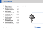
DuoControl switching facility . . . . . . . . 65
7.3.6
7.4
7.4.1
7.4.2
7.4.3
7.4.4
7.5
7.6
7.7
7.7.1
7.7.2
7.7.3
7.7.4
7.7.5
7.8
7.8.1
7.8.2
7.8.3
7.9
7.9.1
7.9.2
7.10
3
Contents
9
Electrical system . . . . . . . . . . . . . 67
12
9.1
9.2
9.2.1
9.3
9.3.1
9.3.2
9.3.3
9.4
9.4.1
General safety instructions . . . . . . . . . 67
12 V power supply . . . . . . . . . . . . . . . . 67
Living area battery . . . . . . . . . . . . . . . . 67
Transformer/rectifier (EBL 99) . . . . . . . 69
Battery cut-off switch . . . . . . . . . . . . . . 70
Battery monitoring . . . . . . . . . . . . . . . . 71
Charging the battery . . . . . . . . . . . . . . 71
Panel LT 410 . . . . . . . . . . . . . . . . . . . . 71
V/tank gauge for battery voltage and
water or waste water levels . . . . . . . . . 72
Battery alarm for the living area
battery . . . . . . . . . . . . . . . . . . . . . . . . . 72
12 V main switch . . . . . . . . . . . . . . . . . 72
12 V indicator lamp . . . . . . . . . . . . . . . 73
230 V indicator lamp . . . . . . . . . . . . . . 73
230 V power supply . . . . . . . . . . . . . . . 73
230 V connection . . . . . . . . . . . . . . . . . 73
Fuses . . . . . . . . . . . . . . . . . . . . . . . . . . 74
Main fuse . . . . . . . . . . . . . . . . . . . . . . . 74
12 V fuses . . . . . . . . . . . . . . . . . . . . . . 74
230 V fuse . . . . . . . . . . . . . . . . . . . . . . 76
12.1
12.1.1
12.1.2
12.1.3
12.1.4
12.1.5
12.2
12.3
12.3.1
12.4
12.4.1
12.4.2
12.4.3
13.4.1
13.4.2
13.4.3
13.4.4
13.4.5
10.3
10.3.1
10.4
10.5
10.5.1
10.5.2
10.5.3
10.5.4
Appliances . . . . . . . . . . . . . . . . . . . 77
General . . . . . . . . . . . . . . . . . . . . . . . . 77
Heater . . . . . . . . . . . . . . . . . . . . . . . . . 77
To heat properly. . . . . . . . . . . . . . . . . . 78
Truma Combi hot-air heater. . . . . . . . . 78
Heater for waste water tank and waste
water pipes (winter comfort package) . 81
Boiler . . . . . . . . . . . . . . . . . . . . . . . . . . 81
Truma Combi boiler . . . . . . . . . . . . . . . 82
Gas cooker. . . . . . . . . . . . . . . . . . . . . . 84
Refrigerator . . . . . . . . . . . . . . . . . . . . . 85
Refrigerator ventilation grill . . . . . . . . . 86
Operation (Dometic 4 series) . . . . . . . . 86
Operation (Waeco). . . . . . . . . . . . . . . . 88
Refrigerator door locking mechanism . 89
11
Sanitary fittings . . . . . . . . . . . . . . 91
11.1
11.2
11.2.1
11.3
11.4
11.5
11.6
11.6.1
11.6.2
11.7
Water supply, general . . . . . . . . . . . . . 91
Water tank . . . . . . . . . . . . . . . . . . . . . . 91
20 l maximum filling . . . . . . . . . . . . . . . 92
Waste water tank . . . . . . . . . . . . . . . . . 92
Water system . . . . . . . . . . . . . . . . . . . . 94
Toilet compartment . . . . . . . . . . . . . . . 95
Vario toilet compartment . . . . . . . . . . . 96
Converting into a shower cubicle . . . . . 96
Conversion to toilet compartment . . . . 96
Thetford toilet . . . . . . . . . . . . . . . . . . . . 96
9.4.2
9.4.3
9.4.4
9.4.5
9.5
9.5.1
9.6
9.6.1
9.6.2
9.6.3
10
10.1
10.2
10.2.1
10.2.2
10.2.3
4
13
13.1
13.2
13.3
13.4
13.5
13.6
13.7
13.8
14
Care . . . . . . . . . . . . . . . . . . . . . . . . . .99
External care . . . . . . . . . . . . . . . . . . . .99
Washing with a high-pressure cleaner .99
Washing the vehicle . . . . . . . . . . . . . . .99
Windows of acrylic glass . . . . . . . . . .100
Waste water tank . . . . . . . . . . . . . . . .100
Entrance step . . . . . . . . . . . . . . . . . . .100
Internal care . . . . . . . . . . . . . . . . . . . .100
Winter care . . . . . . . . . . . . . . . . . . . . .101
Winter operation . . . . . . . . . . . . . . . . .102
Lay-up. . . . . . . . . . . . . . . . . . . . . . . . .102
Temporary lay-up . . . . . . . . . . . . . . . .102
Winter lay-up . . . . . . . . . . . . . . . . . . .103
Starting up the vehicle after a
temporary lay-up or after lay-up over
winter . . . . . . . . . . . . . . . . . . . . . . . . .104
Maintenance . . . . . . . . . . . . . . . . .105
Official inspections . . . . . . . . . . . . . . .105
Inspection work. . . . . . . . . . . . . . . . . .105
Maintenance work . . . . . . . . . . . . . . .105
Replacing bulbs and fluorescent
tubes . . . . . . . . . . . . . . . . . . . . . . . . . .105
Ceiling lamp . . . . . . . . . . . . . . . . . . . .106
Room lamp . . . . . . . . . . . . . . . . . . . . .106
Halogen spotlight (with glass shade) .107
Halogen spotlight (movable) . . . . . . . .107
Surface-mounted halogen light
(swiveling). . . . . . . . . . . . . . . . . . . . . .108
Replacing the battery at the lamp in the
pop-up roof . . . . . . . . . . . . . . . . . . . . .108
Spare parts . . . . . . . . . . . . . . . . . . . . .109
Vehicle identification plate . . . . . . . . .109
Warning and information stickers . . . .110
14.1
14.2
14.3
14.4
14.5
14.5.1
14.5.2
14.6
14.7
Troubleshooting . . . . . . . . . . . . .111
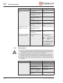
Electrical system. . . . . . . . . . . . . . . . .111
Gas system. . . . . . . . . . . . . . . . . . . . .112
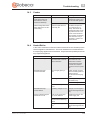
Cooker . . . . . . . . . . . . . . . . . . . . . . . .113
Heater/Boiler. . . . . . . . . . . . . . . . . . . .113
Refrigerator. . . . . . . . . . . . . . . . . . . . .114
Dometic refrigerator without AES . . .114
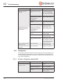
Waeco refrigerator . . . . . . . . . . . . . . .115
Water supply. . . . . . . . . . . . . . . . . . . .116
Body . . . . . . . . . . . . . . . . . . . . . . . . . .116
15
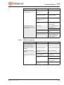
Technical data . . . . . . . . . . . . . . .117
15.1
15.2
15.3
Weights. . . . . . . . . . . . . . . . . . . . . . . .117
Dimensions . . . . . . . . . . . . . . . . . . . . .117
Equipment . . . . . . . . . . . . . . . . . . . . .118
Motorhome - 02/11-0 - PSL-MJ11-00 EN
Records
1.1
Vehicle document
1
1Records
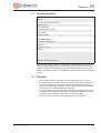
Vehicle data
Model:
Car manufacturer/type of engine:
Serial number:
Initial registration:
Purchased from company:
Key number:
Chassis number:
Customer address
Surname, Christian name:
Street, no.:
Postal code, town:
E-mail:
Dealer's stamp and signature
We reserve the right to alter the construction, equipment and the scope of
delivery. Special equipment is also listed that is not included in the standard
scope of delivery. The descriptions and illustrations in this brochure do not
relate to a particular version. For all details, only the respective equipment list
is valid.
1.2
Warranty
1. The legal guarantee and product warranty rights apply for the vehicle.
2. It is advisable to present the vehicle for inspection by a Globecar dealer at
the end of the first year in order to assert any warranty claims that may
arise. The presentation should take place 2 months at the latest after the
anniversary of the initial registration (or delivery).
As proof that the inspection has been completed, the inspection has to be
confirmed on the corresponding page in this operating manual by a stamp,
the date and the signature of the respective Globecar dealer.
3. The costs of the inspection are to be paid by the vehicle owner.
Motorhome - 02/11-0 - GLO-MJ11-00EN
5
1
Records
1.3
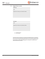
Inspection records
Delivery
Date:
Signature and stamp of the Globecar dealer:
1th year
Date:
Signature and stamp of the Globecar dealer:
No defects found
Found defects:
Should it be determined during an inspection that additional work is necessary,
then the carrying out of this work is dependent on the customer commissioning
this to be done. Please also adhere to the service intervals stipulated by the
manufacturers of the individual equipment. Information is included in the
service documents enclosed.
6
Motorhome - 02/11-0 - GLO-MJ11-00EN
Records
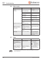
1.4
1
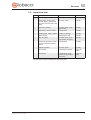
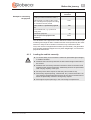
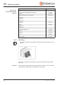
Inspection plan
Pos.
Component
Activity
Interval
Joints, hinges
Lubricate
Annually
Refrigerator, heater, boiler,
cooker, lighting, storage flap
and door closures, toilet, seat
belts
Function check
Annually
Windows, skylights
Function check, water
ingress test
Annually
Upholstery, curtains, blinds
Visual check
Annually
Sealing strips, edges, -rubber
Check for damage
Annually
Water supply
Water ingress test
Annually
Hot-air system
Function check, clean
fan wheel if necessary
Annually
Underbody protection, fastening of the underbody attachments
Visual check
Annually
Electrical system
Function check
Annually
Gas system
Official gas inspection
Every two
years
Underbody
Visual check, repair
underbody protection if
necessary
Every two
years
We reserve the right to modify the inspection plan.
Motorhome - 02/11-0 - GLO-MJ11-00EN
7
1
8
Records
Motorhome - 02/11-0 - GLO-MJ11-00EN
Introduction
2
Please read this instruction manual completely before
using the vehicle for the first time!
2Introduction
Always keep this instruction manual in the vehicle. Also inform all other users
of the safety regulations.
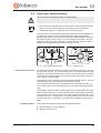
X The non-observance of this symbol can lead to personal injury.
Z The non-observance of this symbol can lead to damage being caused to,
or inside the vehicle.
Z This symbol indicates recommendations or special aspects.
Z This symbol indicates actions which lead to environmental awareness.
This instruction manual contains sections which describe model-specific equipment or special equipment. These sections are not specially
marked. It may be that your vehicle has not been fitted with this special
equipment. In some cases, the actual equipment of your vehicle may
therefore be different from that shown in some illustrations and descriptions.
However, your vehicle may be fitted with other special equipment not
described in this instruction manual.
Special equipment is described when an explanation is required.
Adhere to the instruction manuals which are separately enclosed.
Z The details "right", "left", "front" and "rear" always refer to the vehicle in
direction of travel.
Z All dimensions and weight details are "approximate".
Should the vehicle be subjected to damage due to a failure to follow the
instructions in this instruction manual, then the warranty claim is deemed
invalid.
Our vehicles are subjected to continuous development. Please understand
that we reserve the right to alter the form, equipment and technology. Therefore, no claims can be made against the manufacturer as a result of the contents of this instruction manual. The equipment which was known and included
at the time of going to press is described.
The reprinting, translation and copying, including extracts is not permitted
without prior written authorisation from the manufacturer.
Motorhome - 02/11-0 - GLO-MJ11-00EN
9
2
Introduction
2.1
General
The vehicle is constructed in accordance with the latest technology and the
recognised safety regulations. Nevertheless, personal injury may result and
the vehicle may be damaged if the safety instructions in this instruction manual
are not followed.
Depending on the configuration, the first-aid kit and hazard warning triangle
are not included as standard. Equip the vehicle with a first-aid kit and hazard
warning triangle before using it for the first time. In case of vehicles with a
gross weight exceeding 3.5 t a flashing hazard warning light has to be carried
additionally on the vehicle.
Only use the vehicle in a technically impeccable condition. Follow the instructions in the instruction manual.
Malfunctions which impair the safety of persons or the vehicle should be
immediately remedied by qualified personnel. To avoid further damages,
observe the duty to avert, minimise or mitigate loss for the user during faults.
Have the vehicle's braking and gas systems inspected and repaired by an
authorised specialist workshop only.
Alterations to the body are only to be carried out with the authorisation of the
manufacturer.
The vehicle is designed for the exclusive transport of persons. Luggage and
accessories may only be transported up to the maximum permissible gross
weight.
Observe the test and inspection periods stipulated by the manufacturer.
2.2
Environmental tips
Z Do not impair the tranquility and spruceness of nature.
Z Remember that: All kinds of waste water and household waste are not to
be disposed of in drains or in the open countryside.
Z Only empty the waste water tank and toilet cassette or sewage tank at dis-
posal stations at the camping or caravan sites, which are especially provided for this purpose. When stopping in towns and communities, observe
the instructions at caravan sites or ask where there are disposal stations.
Z Collect waste water on board only in the waste water tank or, if need be, in
other vessels suitable to this purpose.
Z Empty waste water tank as often as possible, even when it is not com-
pletely full (hygiene).
If possible, flush out waste water tank and, if necessary, drainage pipe with
fresh water every time it is emptied.
Z Never allow the toilet cassette or sewage tank to become too full. Empty
the toilet cassette or sewage tank frequently, at the latest as soon as the
level indicator lights up.
Z Separate household waste according to glass, tin cans, plastic and wet
waste also when on a journey. Enquire at the town or community authority
about disposal points. Household waste is not to be disposed of in waste
paper baskets which are situated at car parks.
Z Empty waste bins as often as possible into the cans or containers that are
provided for this purpose. This helps to avoid unpleasant smells and an
accumulation of rubbish on board.
10
Motorhome - 02/11-0 - GLO-MJ11-00EN
Introduction
2
Z When parked, do not allow the engine to run more than necessary. When
running idle, a cold engine releases more contaminants than usual. The
running temperature of the engine is achieved more quickly whilst the
vehicle is in motion.
Z Use an environmentally-friendly WC chemical agent for the WC which can
also be biologically degraded and only use small doses.
Z When staying in towns and communities for longer periods, search for
parking areas which are especially designated for motorhomes. Enquire at
the town or community authority about parking spaces.
Z Always leave the parking places in a clean condition.
Motorhome - 02/11-0 - GLO-MJ11-00EN
11
2
12
Introduction
Motorhome - 02/11-0 - GLO-MJ11-00EN
Safety
3.1
3.1.1
3
Fire prevention
3Safety
Avoidance of fire risks
X Never leave children in the vehicle unattended.
X Keep flammable materials clear of heating and cooking appliances.
X Lights can get very hot. WHen the light is switched on, a safety distance
of 30 cm to combustible material has to be maintained. Fire hazard!
X Never use portable heating or cooking appliances.
X Only authorised qualified personnel may modify the electrical system,
the gas system or the appliances.
3.1.2
Fire-fighting
X Always carry a dry powder fire extinguisher in the vehicle. The fire extin-
guisher must be approved, tested and close at hand.
X Have the fire extinguisher tested at regular intervals by authorised qual-
ified personnel. Observe the date of testing.
X The fire extinguisher is not included in the scope of delivery.
X Always keep a fire blanket at hand near the cooker.
3.1.3
In case of fire
X Evacuate all passengers.
X Cut off the electrical power supply and disconnect from the mains.
X Close regulator tap on the gas bottle.
X Sound the alarm and call the fire brigade.
X Fight the fire if this is possible without risk.
Z Keep escape routes clear.
Z Observe the fire extinguisher instructions for use.
3.2
General
X The oxygen in the vehicle interior is used up by breathing and the use of
gas operated appliances. That is why the oxygen needs to be replaced
on a constant basis. For this purpose, forced ventilation options (e.g.
skylights with forced ventilation, mushroom-shaped vents or floor vents)
are fitted to the vehicle. Never cover or block forced ventilations from the
inside or outside with objects such as e.g. a winter mat. Keep forced ventilations clear of snow and leaves. There is a danger of suffocation due
to increased CO2 levels.
X Observe the headroom of the doors.
X Gas lines and electrical cables are laid in the floor. Never drill holes or
screw screws into the floor. There is danger of a gas explosion or of a
power cut or short circuit due to damage to a line or cable.
Motorhome - 02/11-0 - GLO-MJ11-00EN
13
3
Safety
Z As far as the fitted appliances (heater, cooker, refrigerator, etc.) and the
base vehicle (engine, brakes, etc.) are concerned, the instruction manuals
are authoritative. It is imperative that they be observed.
Z Fitting accessories or special equipment can alter the dimensions, weight
and road behaviour of the vehicle. Some of the parts must be entered in
the vehicle papers.
Z Only use wheel rims and tyres which are approved for the vehicle. Informa-
tion concerning the size of the approved wheel rims and tyres is included
in the vehicle documents or can be obtained from authorised dealers and
service centres.
Z Firmly apply the handbrake when parking the vehicle.
Z When leaving the vehicle, it is imperative that all doors, external flaps and
windows are closed.
Z Hazard warning triangle and first-aid kit conforming to DIN 13164 are pre-
scribed by law and must be carried on the vehicle.
Z Only move the vehicle on the road if the driver has a driver's license valid
for the vehicle class.
Z When selling the vehicle, hand over all instruction manuals for the vehicle
and the fitted appliances.
3.3
Road safety
X Before commencing the journey, carry out a functional check of indi-
cating and lighting equipment, the steering and the brakes.
X If the vehicle has been stationary for a long period (approx. 10 months)
have the braking and gas systems checked by an authorised specialist
workshop.
X Before starting the journey and also after short breaks check whether the
entrance step has been retracted completely.
X Fold in the pop-up roof fully and lock it into place before commencing the
journey.
X Before commencing the journey, open and secure the shades on the
windscreen and on the driver's and front passenger's windows.
X Before starting the journey, rotate the seat in the direction of travel and
lock in position. The rotating seats must remain locked in the direction of
travel during the journey.
X Before starting your journey, remove the television from the support and
store it securely.
X During the journey, persons are only to sit on the permitted seats (see
Chapter 5). The authorised number of seats is stipulated in the vehicle
documents.
X Before starting the journey fasten your seat belt and keep it fastened
during the journey.
X Always secure children with the child-protection equipment that is man-
datory for the respective child's size and weight.
X Factory-set three-point safety belts must be used when attaching child
restraint systems.
X The base vehicle is a commercial vehicle (small truck). Adapt your
manner of driving correspondingly.
14
Motorhome - 02/11-0 - GLO-MJ11-00EN
Safety
3
X Observe the overall height of the vehicle (including roof loads) at under-
passes, tunnels, etc.
X In winter, the roof must be free of snow and ice before commencing the
journey.
Z Before commencing the journey, distribute the vehicle payload evenly (see
Chapter 4).
Z When loading the vehicle and when taking a rest from driving, in order to
load luggage or food, for example, observe the maximum permissible
gross weight and axle loads (refer to vehicle documents).
Z Before commencing the journey, ensure that all cupboard doors, the toilet
door and all drawers and flaps are secure. Engage the refrigerator door
securing device. Lock the folding wall of the Vario toilet compartment.
Z Before commencing the journey, close windows and skylights.
Z Before commencing the journey, close all external flaps and lock them.
3.4
Towing
X Care is to be taken when connecting and detaching a trailer. Risk of acci-
dent and injury!
X No persons are to be between the towing vehicle and the trailer during
positioning for connecting and detaching.
3.5
3.5.1
Gas system
General information
X Close all gas isolator taps and the regulator tap before commencing the
journey and when leaving the vehicle.
X No appliance (e.g. heating or refrigerator) that is operated through the
built-in burner may be operational while fuel is being filled up, on ferries
or in the garage. Danger of explosion!
X If an appliance is operated through a burner, do not start the appliance
up in closed areas (e.g. garages). Danger of poisoning and suffocation!
X Have the gas system serviced, repaired or altered by an authorised
workshop only.
X Have the gas system checked by an authorised specialist workshop
before starting up and according to the national regulations. This also
applies for not registered vehicles. For modifications to the gas system
have the gas system immediately checked by an authorised specialist
workshop.
X The gas pressure regulator and the exhaust gas pipes also have to be
checked. The gas pressure regulator has to be replaced at least every
10 years. The vehicle owner is responsible for seeing that this is carried
out.
X In case of a defect of the gas system (gas odour, high gas consumption)
there is danger of explosion! Close the regulator tap on the gas bottle
immediately. Open doors and windows and ventilate well.
X In case of a defect in the gas system: Do not smoke; do not ignite any
open flames, and do not operate electric switches (light switches etc.).
Motorhome - 02/11-0 - GLO-MJ11-00EN
15
3
Safety
X Have the defect in the gas system repaired by an authorised specialist
workshop.
X Open a skylight or a window before taking open sources of combustion
(gas cooker) into service.
X Do not use the gas cooker or gas oven for heating purposes.
X If the vehicle or gas devices are not used, close the regulator tap on the
gas bottle.
X If there are several gas devices, each gas device must have its own gas
isolator tap. If individual gas devices are not in use, close the respective
gas isolator tap.
X Ignition safety valves must close within 1 minute after the gas flame has
extinguished. A clicking sound is audible. Check function from time to
time.
X The installed gas appliances are designed for use solely with propane or
butane gas or a mixture of both. The gas pressure regulator as well as
all installed gas devices are set for a gas pressure of 30 mbar.
X Propane gas is capable of gasification up to -42 °C, whereas butane gas
gasifies at 0 °C. Below these temperatures no gas pressure is available.
Butane gas is unsuitable for use in winter.
X Regularly inspect the gas tube fitted to the gas bottle connection for
tightness. The gas tube must not have any tears and must not be
porous. Have the gas tube replaced by an authorised specialist workshop no later than 10 years after the manufacturing date. The operator
of the gas system must see to it that the parts are replaced.
X Due to its function and construction, the gas bottle compartment is a
space which is open to the exterior. Never cover or block the standard
forced ventilation. Otherwise leaking gas cannot be dispersed to the outside.
X Do not use the gas bottle compartment as storage space as it is not
moisture-proof.
X Secure the gas bottle compartment in order to prevent unauthorised per-
sons opening it. To do so lock the access.
X The regulator tap on the gas bottle must be accessible.
X Only connect gas-operated devices (e.g. gas grill) which have been
designed for a gas pressure of 30 mbar.
X The exhaust gas pipe must be fitted tightly to the heating system and to
the vent and must be sealed. The exhaust gas pipe must not show any
evidence of damage.
X Exhaust fumes must be able to escape into the atmosphere unhindered
and fresh air must be able to enter unhindered. Therefore keep the
waste gas vents and intake openings clean and free (e.g. of snow and
ice). No snow walls or aprons may be allowed to lie against the vehicle.
16
Motorhome - 02/11-0 - GLO-MJ11-00EN
Safety
3.5.2
3
Gas bottles
X Gas bottles are only to be transported within the designated gas bottle
compartment.
X Place gas bottles vertically in the gas bottle compartment.
X Tie down gas bottles so that they are unable to turn or tilt.
X If the gas bottles are not connected to the gas tube, always place the
protective cap on top.
X Close the regulator tap on the gas bottle before the gas pressure regu-
lator or gas tube are removed from the gas bottle.
X Use your hands only to connect the gas pressure regulator or the gas
tube to the gas bottles. Do not use any tools.
X Only use special gas pressure regulators with a safety valve designed
for vehicle use. Other gas pressure regulators are not permitted and
cannot meet the demanding requirements.
X Use only 11 kg or 5 kg gas bottles. Camping gas bottles with a built-in
reflux valve (blue bottle with max. 2.5 or 3 kg content) are permitted in
exceptional cases with a safety valve.
X Never block the ventilation openings in the floor under the gas bottles.
3.6
Electrical system
X Only allow qualified personnel to work on the electrical system.
X Prior to carrying out work on the electrical system, switch off all devices
and lights, disconnect the battery and disconnect the vehicle from the
mains.
X Only use original fuses with the stipulated values.
X Only replace defective fuses when the cause of the defect is known and
has been remedied.
X Never bridge or repair fuses.
3.7
Water system
X Water left standing in the water tank or in the water pipes becomes
undrinkable after a short period. For this reason, rinse the water pipes
and the water tank thoroughly with several litres of fresh water before
each use of the vehicle. To do this, open all water taps. After each use
of the vehicle completely empty the water tank and the water pipes.
Z If the vehicle is not used for several days or if it is not heated when there is
a risk of frost, empty the entire water system. Leave the water taps on in
central position. Leave the safety/drainage valve (if available) and all drain
cocks open. Frost damage to appliances, frost damage to the vehicle and
deposits in water-carrying components can be avoided in this way.
Motorhome - 02/11-0 - GLO-MJ11-00EN
17
3
18
Safety
Motorhome - 02/11-0 - GLO-MJ11-00EN
4
Before the journey
4.1
Payload
4Before the journey
X Excessive payload and the wrong tyre pressure can cause the tyre to
burst. You can lose control of the vehicle.
X Adapt your speed to the payload. The stopping distance is longer when
the payload is higher.
Z The maximum permissible gross weight stated in the vehicle documents is
not to be exceeded by the payload.
Z Built-in accessories and special equipment reduce the payload.
Z Adhere to the axle load stated in the vehicle documents.
On loading, make sure that the payload's centre of gravity is as low as possible
(directly above the floor of the vehicle). Otherwise this may affect the driving
characteristics of the vehicle.
4.1.1
Terms
Z In technical and scientific texts the term "mass" has replaced the term
"weight". However the term "weight" is still the more common term in general usage. To contribute toward understanding the term "mass" is therefore only used in established phrases in the following passages.
Maximum permissible
gross weight in a laden
condition
The maximum permissible gross weight in a laden condition is the weight that
a vehicle may never exceed.
The maximum permissible overall weight in laden condition consists of the
mass in ready-to-drive condition and of the payload.
The manufacturer has specified the maximum permissible gross weight in a
laden condition in Field F.1 of the vehicle documents.
Mass in ready-to-drive
condition
Payload
The manufacturer specifies the mass in ready-to-drive conditions in Field G of
the vehicle documents.
The payload is made up as follows:
z Conventional load
z Additional equipment
z Personal equipment
Explanations of the individual components of the payload are contained in the
following text.
Conventional load
The conventional load is the weight specified by the manufacturer for the passengers.
Conventional load means: 75 kg are calculated for every seat specified by the
manufacturer, regardless of how much the passengers actually weigh. The
driver's seat is already included as part of the mass in ready-to-drive condition
and must not be calculated as part of the conventional load.
The manufacturer specifies the number of seats in Field S.1 of the vehicle documents.
Motorhome - 02/11-0 - GLO-MJ11-00EN
19
4
Before the journey
Additional equipment
Additional equipment includes accessories and special equipment. Examples
of additional equipment include:
z
z
z
z
z
Tow coupling
Roof racks
Awning
Bike or motorcycle rack
Satellite unit
Information about the weights of the various special equipment devices can be
obtained from the manufacturer.
Personal equipment
Personal equipment includes all items in the vehicle that are not included in
the conventional load and the additional equipment. For example, personal
equipment can include the following:
z
z
z
z
z
z
z
z
z
Foodstuffs
Crockery
Television
Radio
Clothes
Bedding
Toys
Books
Toiletries
No matter where kept, personal equipment also includes:
z
z
z
z
z
4.1.2
Animals
Bikes
Boats
Surfboards
Sports equipment
Calculating the payload
X Payload calculation at the manufacturer is partly based on all-inclusive
weights. For safety reasons, the maximum permissible gross weight in
a laden condition must not be exceeded.
X Only the maximum permissible gross weight and the mass in a ready-to-
drive condition, not the actual weight of the vehicle, is stated in the
vehicle documents. For your own safety, we recommend that you have
your loaded vehicle (with passengers) weighed on a public weighbridge
before you set out on your journey.
The payload (see Section 4.1.1) is the difference in weight between
z Maximum permissible gross weight in a laden condition and
z Vehicle mass complete in a ready-to-drive condition.
20
Motorhome - 02/11-0 - GLO-MJ11-00EN
Before the journey
Mass in kg to be
calculated
Example for calculating
the payload
Maximum permissible gross weight according to vehicle documents, Field F.1
Vehicle mass in a ready-to-drive condition, including basic equipment according
to vehicle documents, Field G
This results in a permissible payload
of
Conventional load, e.g. 3 persons at
75 kg each
Additional equipment
For the personal equipment this
results in
4
Calculation
3300
- 2720
580
- 225
- 40
= 315
The calculation of the payload from the difference between the maximum permissible gross weight in laden condition and the mass specified by the manufacturer in ready-to-drive condition is however only a theoretical value.
Only if the vehicle is weighed with full tanks (fuel and water), full gas bottles
and complete additional equipment on a public weighbridge, can the actual
payload be determined.
4.1.3
Loading the vehicle correctly
X To ensure safety never exceed the maximum permissible gross weight
in a laden condition.
X Distribute the load evenly between the left-hand and right-hand sides of
the vehicle.
X Distribute the load evenly between both axles. Observe the axle loads
specified in the vehicle documents. Additionally observe the permissible
load-carrying capacity of the tyres.
X Securely store all the objects so that they cannot slide or slip.
X Store heavy objects (awning, canned food, etc.) close to the axles. Low-
lying storage compartments whose doors do not open in the direction of
travel are particularly suited for storing heavy objects.
X Store lighter objects (laundry) in the roof storage compartments.
Motorhome - 02/11-0 - GLO-MJ11-00EN
21
4
Before the journey
4.2
Entrance step
X Before starting the journey and also after short breaks check whether the
entrance step has been retracted completely.
X Do not stand in the direct range of movement of the entrance step while
the entrance step is being extended or retracted.
X Do not step on the entrance step until it has extended completely. There
is a risk of injury!
X Never raise or lower persons or loads with the entrance step.
Z Clean dust and dirt regularly from the entrance step, do not grease or oil
moving parts.
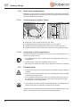
4.2.1
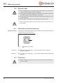
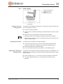
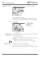
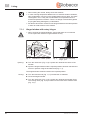
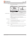
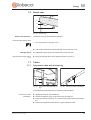
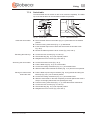
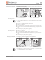
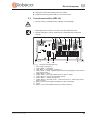
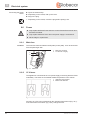
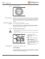
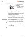
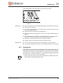
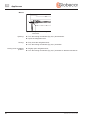
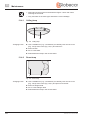
Operating switch
Electrically operated entrance step
The switch to operate the entrance step is located on the inside of the vehicle
in the area of the conversion door.
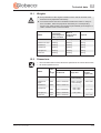
Fig. 1
Extending:
Operating switch entrance
step
Press the rocker switch (Fig. 1,1) down until the entrance step has
extended completely.
Retracting:
Press the rocker switch (Fig. 1,1) up until the entrance step has retracted
completely.
4.3
Television
X Before starting your journey, remove the television from the support and
store it securely.
22
Motorhome - 02/11-0 - GLO-MJ11-00EN
Before the journey
4.4
4
Road safety
X Check the tyre pressure before a journey and at 2-week intervals. Wrong
tyre pressure causes excessive wear and can lead to damage or even
to tyre burst. You can lose control of the vehicle.
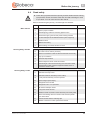
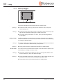
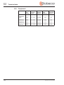
Before commencing the journey, work through the checklist:
No.
Base vehicle
Housing body, outside
Housing body, inside
Motorhome - 02/11-0 - GLO-MJ11-00EN
Checks
1
All vehicle documents are on board
2
Tyres in proper condition
3
Vehicle lighting, brake and reversing lights function
4
Oil level at engine, gear unit and power steering checked
5
Coolant and liquid for windshield washer system topped up
6
Breaks function
7
Brakes react evenly
8
When braking, the vehicle remains on track
9
Awning completely retracted
10
Roof free of snow and ice (in winter)
11
External connections and lines disconnected and stored away
12
Pop-up roof folded in
13
Entrance step retracted
14
External flaps and doors closed and locked
15
Overall height of the vehicle including roof rack when loaded
measured and noted. Keep the height information close at
hand in the driver's cabin
16
Windows and skylights closed and locked
17
Television securely stored
18
Television antenna retracted (if one is built in)
19
Loose parts stored away or fixed in position
20
Open storage spaces empty
21
Refrigerator door secured
22
Refrigerator set to 12 V operation
23
All drawers and flaps closed
24
Living area doors secured
25
Children's seats mounted to seats with three-point safety belts
26
Swivel seat locking device for driver's seat and front passenger's seat locked
27
Curtains hooked into the retaining clips
28
Shades in the driver's cabin opened and secured
Checked
23
4
Before the journey
Gas system
Electrical system
No.
Checks
Checked
29
Gas bottles firmly fixed in the gas bottle compartment so that
they are unable to turn
30
Protective cap set on top of the gas bottle
31
Regulator tap on the gas bottle and gas isolator taps are
closed
32
Check the battery voltage of the starter battery and the living
area battery (see Chapter 9). If the panel indicates that the
battery voltage is too low, the respective battery has to be
recharged. Observe the instructions in Chapter 9
Z Commence the journey with a fully charged starter
battery and living area battery.
24
Motorhome - 02/11-0 - GLO-MJ11-00EN
During the journey
5.1
Driving the motorhome
5
5During the journey
X The base vehicle is a commercial vehicle (small truck). Adapt your
manner of driving correspondingly.
X Before starting the journey and also after short breaks check whether the
entrance step has been retracted completely.
X Always wear a seat belt during the journey at those seats where a seat
belt is mounted.
X Never open the seat belt during the journey.
X Passengers must remain in the seats provided.
X The door lock may not be opened.
X Avoid braking suddenly.
X Only change the destination on the navigation system when the vehicle
is at a standstill. Drive to a car park or stop in a safe area when changing
the destination.
X Do not play a DVD on the monitor of the navigation system during the
journey.
Z Drive slowly on bad roads.
Z If an accident occurs as a result of these instructions not being observed,
the manufacturer will not be responsible for damages caused.
Z The safety measures specified in Chapter 3 have to be observed.
5.2
Driving speed
X The vehicle is equipped with a powerful engine. Meaning that you have
sufficient power reserves in difficult traffic situations. This high power
allows a high end speed and requires above-average driving skills.
X The vehicle provides a huge surface exposed to wind. Particular danger
arises when a side wind suddenly occurs.
X Uneven or one-sided loading changes the road behavior.
X On unknown roads the road surface conditions may be difficult and
unexpected traffic situations may arise. Therefore adapt your driving
speed to the respective traffic situation and the ambient situation for your
safety.
X Observe the statutory speed limits that apply in the respective country.
Z The skylights and windows are not designed for high speeds. Excessive
speeds can result in noise development that is too high.
Motorhome - 02/11-0 - GLO-MJ11-00EN
25
5
During the journey
5.3
Seat belts
The vehicle is equipped with automatic three-point seat belts at those seats in
the living area for which a seat belt is stipulated by law. The corresponding
national regulations apply for using a seat belt.
X Before starting the journey fasten your seat belt and keep it fastened
during the journey.
X Do not damage or clamp in the belts. Have damaged seat belts replaced
by an authorised specialist workshop.
X Do not change the belt attachment points, the automatic retractor and
the belt locks.
X Check the screwed connections of the seat belts at intervals in order to
ensure that they are firmly seated.
X Use each seat belt for one adult person only.
X Do not belt up objects together with persons.
X Seat belts are not sufficient for persons who are less than 150 cm tall. In
this case use additional retention devices. Observe the test certificates.
X Factory-set three-point safety belts must be used when attaching child
restraint systems.
X Replace (have replaced) the seat belts that were in use during an acci-
dent.
X Do not tilt the backrest of the seat too far back during the journey. Oth-
erwise the effectiveness of the seat belt is no longer ensured.
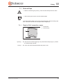
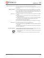
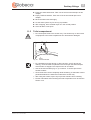
5.3.1
Using the safety belt correctly
X Do not twist the belt. The belt must be positioned smoothly against the
body.
X Before applying the seat belt, adopt the correct sitting position.
The safety belt is applied correctly when a fist still fits between your body and
a safety belt.
5.4
Driver's seat and front passenger's seat
X Before starting the journey, rotate the seat in the direction of travel and
lock in position.
X Lock the seats in the direction of travel and do not turn them during the
journey.
Z The driver's and front passenger's seat are a part of the base vehicle,
depending on model and vehicle equipment. In this case the adjustment of
the seats is described in the operating instructions of the base vehicle.
26
Motorhome - 02/11-0 - GLO-MJ11-00EN
During the journey
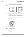
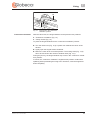
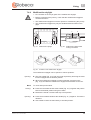
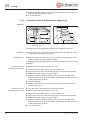
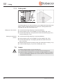
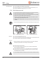
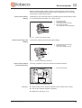
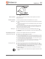
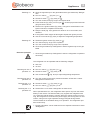
5.4.1
Seats (Aguti)
1
2
3
4
Fig. 2
Rotating seats into
driving position
5
Lengthways adjustment
Armrest adjustment
Rotating
Backrest adjustment
Driver's and front passenger's
seats (Aguti)
The seats can be rotated in any direction. The seats can only be locked in position in the direction of travel.
Push both armrests upward.
Push the driver's seat/front passenger's seat backwards or into the central
position.
Rotate the seat in the direction of travel and lock in position.
Z Rotating the seats in the stationary vehicle is described in Chapter 7.
Z Move the seats all the way down or forward before turning. Otherwise, the
seats cannot be turned.
Adjusting the armrest
The height of the armrests is infinitely adjustable.
Turn the knurled wheel (Fig. 2,2) in an anticlockwise direction (when
viewed from the front). The latch of the armrest is released by this.
Move the armrest to the desired position.
Turn the knurled wheel as far as possible in a clockwise direction.
Adjusting an appropriate
seating position
The position of the driver's and front passenger's seats can be adjusted. The
handles which are required for this purpose are positioned to the front, right or
left of the seat.
Pull the handle (Fig. 2,1). The seat can be moved forward or backward.
Turn the knurled knob (Fig. 2,4). The angle of the backrest can be
adjusted.
Motorhome - 02/11-0 - GLO-MJ11-00EN
27
5
During the journey
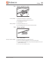
Adjusting the seat height
Depending on the model, the height of the seat is infinitely adjustable.
Fig. 3
Seat height adjustment
Pull the lever (Fig. 3,1) upwards.
Take pressure off or apply pressure to seat. The seat moves up or down.
Release lever when the desired position is reached. The seat is locked.
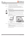
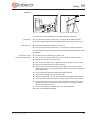
5.4.2
Seats (ISRI)
1
2
3
4
5
1
Armrest adjustment
Lengthways adjustment
Height adjustment
Rotating
Backrest adjustment
5
2
4
Fig. 4
Rotating seats into
driving position
3
Driver's and front passenger's
seats (ISRI)
The seats can be rotated in any direction. The seats can only be locked in position in the direction of travel.
Push both armrests upward.
Push the driver's seat/front passenger's seat backwards or into the central
position.
Rotate the seat in the direction of travel and lock in position.
Z Rotating the seats in the stationary vehicle is described in Chapter 7.
Adjusting the armrest
The height of the armrests is infinitely adjustable.
For ease in handling, first move the armrest slightly upward.
For fine adjustments, turn the handwheel (Fig. 4,1) upwards or downwards.
28
Motorhome - 02/11-0 - GLO-MJ11-00EN
During the journey
Adjusting an appropriate
seating position
5
Both the height and the position of the driver's and front passenger's seats can
be adjusted. The handles which are required for this purpose are positioned to
the front, right or left of the seat.
X The backrest is under strong spring tension. If there is no resistance to
the backrest, it quickly moves forward after unlocking.
Z If the backrest quickly moves forward uncontrolled it can damage the seat-
belt lock.
Pull the handle (Fig. 4,2). The seat can be moved forward or backward.
Pull the handle (Fig. 4,5). The angle of the backrest can be adjusted.
Pull the handle (Fig. 4,3). The seat can be lifted or lowered toward the front.
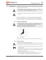
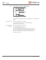
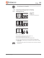
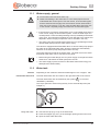
5.5
Seating arrangement
X During the journey, persons are only to sit on the permitted seats. The
authorised number of seats is stipulated in the vehicle documents.
X Sitting on the divans is forbidden during the journey.
X Wearing of seat belts is compulsory at all seats.
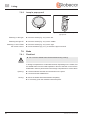
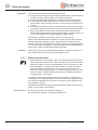
Fig. 5
"Seat" symbol
Seats which may be used during travel are equipped with a sticker (Fig. 5).
5.6
External doors
X Only drive with the external doors locked.
Z Locking the doors can prevent them from opening of their own accord, e.g.
during an accident.
Z Locked doors also prevent forced entry, e.g. when waiting at a set of traffic
lights. However, in an emergency, locked doors make it more difficult for
helpers to enter the vehicle.
Z When leaving the vehicle, always lock the doors.
Z The doors are part of the base vehicle. The opening and closing of the
doors is described in the instruction manual of the base vehicle.
Motorhome - 02/11-0 - GLO-MJ11-00EN
29
5
During the journey
5.7
Filling up with diesel
X No appliance (e.g. heating or refrigerator) that is operated through the
built-in burner may be operational while fuel is being filled up, on ferries
or in the garage. Danger of explosion!
Refer to the instruction manual for the base vehicle for the position of the fuel
filler neck.
30
Motorhome - 02/11-0 - GLO-MJ11-00EN
6
Pitching the motorhome
6.1
Handbrake
6Pitching the motorhome
Firmly apply the handbrake when parking the vehicle.
Z An applied handbrake can prevent the driver's seat from turning. If neces-
sary release the handbrake briefly.
6.2
Entrance step
In order to exit the vehicle, first fully extend the entrance step.
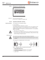
6.3
230 V connection
The vehicle can be connected to a 230 V power supply (see Chapter 9).
6.4
6.4.1
Refrigerator
Absorption refrigerator
12 V operation of the refrigerator is only possible when the vehicle engine is
running. If the vehicle engine is switched off, set the refrigerator to 230 V operation or gas operation.
6.4.2
Compressor refrigerator
The refrigerator only functions in 12 V operation.
Motorhome - 02/11-0 - GLO-MJ11-00EN
31
6
32
Pitching the motorhome
Motorhome - 02/11-0 - GLO-MJ11-00EN
Living
7.1
External flaps
7
7Living
Z Before commencing the journey, close all external flaps and lock them.
Z When leaving the vehicle, close all external flaps.
The external flaps fitted to the vehicle are all fitted with identical locking cylinders. Therefore, all locks can be opened with a single key.
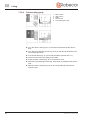
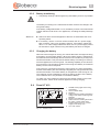
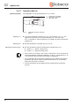
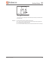
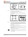
7.1.1
Flap for 230 V connection, square
1
2
External flap
Recessed grip
1
2
Fig. 6
Opening:
Flap for 230 V connection
Grip into the recessed grip (Fig. 6,2) at the external flap (Fig. 6,1) and lift
the external flap upwards.
Closing:
Motorhome - 02/11-0 - GLO-MJ11-00EN
Lower the external flap downward and press it shut.
33
7
Living
7.1.2
External flap Thetford cassette
Z Do not let the external flap fall closed in order to avoid damage.
2
1
2
1
Fig. 7
Opening:
External flap Thetford cassette
Fig. 8
External flap Thetford
cassette 2
Insert the key into the locking cylinder of the push-button lock (Fig. 7,1) and
turn a quarter turn.
Remove the key.
Press both push-button locks (Fig. 7,1 and 2) simultaneously with your
thumb and open the external flap.
Closing:
Close the external flap and press it shut.
Insert the key into the locking cylinder (Fig. 7,1) and turn a quarter turn.
Remove the key.
7.1.3
Cap for the fresh water filler neck
1
2
Fig. 9
Cap for the fresh water filler
neck
Z The fresh water filler neck is identified by the symbol (
)" (Fig. 9,1) or the
word "WASSER" ("WATER").
Opening:
Insert the key in the locking cylinder (Fig. 9,2) and turn it in an anticlockwise
direction.
Remove the cap.
34
Motorhome - 02/11-0 - GLO-MJ11-00EN
Living
Closing:
7
Insert the cap in the fresh water filler neck.
Turn key clockwise.
Remove the key.
7.2
Ventilation
X The oxygen in the vehicle interior is used up by breathing and the use of
gas operated appliances. That is why the oxygen needs to be replaced
on a constant basis. For this purpose, forced ventilation options (e.g.
skylights with forced ventilation, mushroom-shaped vents or floor vents)
are fitted to the vehicle. Never cover or block forced ventilations from the
inside or outside with objects such as e.g. a winter mat. Keep forced ventilations clear of snow and leaves. There is a danger of suffocation due
to increased CO2 levels.
Z Although sufficient ventilation is provided, in certain weather conditions,
condensation can form on metal objects (e.g. screwed connections in the
floor).
Z Additional cold spots can occur at thermal "bridges" (e.g. mushroom-
shaped vents, skylight edges, sockets, filler necks, flaps, etc.).
Condensation
7.3
Ensure that there is a continuous exchange of air by providing frequent and
efficient ventilation. This is the only method for ensuring that condensation is
not formed during cool weather. During the colder season, a pleasant living climate is created if heating output, air distribution and ventilation are synchronised. To avoid draft close the air outlet nozzles on the dashboard and set the
air distribution of the base vehicle to air circulation. If the vehicle is laid up for
a longer period, occasionally ventilate it well, especially in summer as heat
accumulation can occur.
Windows
Z The windows are fitted with a blind and a roller insect screen.
Z If the blind is completely closed, exposure to direct sunlight can cause heat
to accumulate between the blind and the glass window. The window could
be damaged. For that reason, close the blind only 2/3 of the way in direct
sunlight.
Z Before commencing the journey, close the windows.
Z Close and lock the hinged windows at the sliding door and behind the
sliding door before using the sliding door.
Z Open the blinds at the hinged window at the sliding door before using the
sliding door.
Z Depending on the weather, close the windows far enough to prevent mois-
ture from entering.
Z To open and close the hinged windows, open or close all catch levers
which are fitted to the hinged window.
Motorhome - 02/11-0 - GLO-MJ11-00EN
35
7
Living
Z When leaving the vehicle, always close the windows.
Z In case of strong temperature differences or in extreme weather conditions,
light condensation can form on the double-glazed acrylic glass. The glass
is designed in such a way that condensation can evaporate when the
external temperature increases. There is no danger of the double-glazed
acrylic glass being damaged by condensation.
Z Set all the catch levers mounted on the hinged window to the same position
in order to avoid tensions in the window.
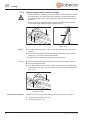
7.3.1
Hinged window with rotary hinges
Z When opening the hinged windows, ensure that there are no torsional
forces. Open and close the hinged windows evenly.
Fig. 10
Opening:
Catch lever in "closed" position
Fig. 11
Hinged window with rotary
hinges, open
Turn the catch lever (Fig. 10,3) a quarter turn towards the centre of the
window.
Open the hinged window until the required position has been reached and
secure in position using the knurled knob (Fig. 11,1).
The hinged window remains locked in the required position.
Closing:
Turn the knurled knob (Fig. 11,1) until the latch is released.
Close the hinged window.
Turn the catch lever (Fig. 10,3) a quarter turn towards the window frame.
The locking catch (Fig. 10,2) is located on the inside of the window catch
(Fig. 10,1).
36
Motorhome - 02/11-0 - GLO-MJ11-00EN
Living
Fig. 12
Continuous ventilation
7
Catch lever in the "continuous
ventilation" position
With the catch lever, the hinged window can be placed in two positions:
z "Continuous ventilation" (Fig. 12)
z "Firmly closed" (Fig. 10)
To place the hinged window into the "continuous ventilation" position:
Turn the catch lever (Fig. 12,3) a quarter turn towards the centre of the
window.
Lightly open the hinged window outwards.
Return the catch lever to its initial position. The locking catch (Fig. 12,2)
has to be moved into the recess of window catch (Fig. 12,1).
During the journey, the hinged window may not be in the "continuous ventilation" position.
If it rains, the "continuous ventilation" hinged window position could lead to
splashing water penetrating the living area. Therefore, close the hinged windows completely.
Motorhome - 02/11-0 - GLO-MJ11-00EN
37
7
Living
7.3.2
Hinged window with automatic hinges
Z Open the window completely in order to unblock the locking device. If the
locking device is not unblocked and the window is closed nevertheless,
there is the danger of the window being torn due to the massive counterpressure.
Z When opening the hinged windows, ensure that there are no torsional
forces. Open and close the hinged windows evenly.
Fig. 13
Opening:
Catch lever in "closed" position
Fig. 14
Hinged window with automatic
hinges, open
Turn the catch lever (Fig. 13,3) a quarter turn towards the centre of the
window.
Open the hinged window to the desired latched position. The automatic
hinge (Fig. 14,1) locks in place automatically.
The hinged window remains locked in the required position.
Closing:
Open the hinged window as wide as necessary until the latch releases.
Close the hinged window.
Turn the catch lever (Fig. 13,3) a quarter turn towards the window frame.
The locking catch (Fig. 13,2) is located on the inside of the window catch
(Fig. 13,1).
Fig. 15
Continuous ventilation
38
Catch lever in the "continuous
ventilation" position
With the catch lever, the hinged window can be placed in two positions:
z "Continuous ventilation" (Fig. 15)
z "Firmly closed" (Fig. 13).
Motorhome - 02/11-0 - GLO-MJ11-00EN
Living
7
To place the hinged window into the "continuous ventilation" position:
Turn the catch lever (Fig. 15,3) a quarter turn towards the centre of the
window.
Lightly open the hinged window outwards.
Turn the catch lever a quarter turn towards the window frame. The locking
catch (Fig. 15,2) has to be moved into the recess of window catch
(Fig. 15,1).
During the journey, the hinged window may not be in the "continuous ventilation" position.
If it rains, the "continuous ventilation" hinged window position could lead to
splashing water penetrating the living area. Therefore, close the hinged windows completely.
7.3.3
Sliding window without lock
1
Fig. 16
Opening:
Sliding window
Press the handle (Fig. 16,1) and push or pull it forwards or backwards at
the same time.
Open window half up to the required position.
Closing:
Motorhome - 02/11-0 - GLO-MJ11-00EN
Close the window as far as possible and let the handle lock in place.
39
7
Living
7.3.4
Blind and roller insect screen
The windows are fitted with a blind and a roller insect screen. The blind and
insect screen can be adjusted separately.
1
2
Fig. 17
Hinged window
Blind
Closing:
Grip into the notch (Fig. 17,2) and pull the blind from the top downwards as
far as wished.
Opening:
Grip into the notch (Fig. 17,2) and push the blind upwards.
Roller insect screen
Closing:
Opening:
7.3.5
Use the handle (Fig. 17,1) to pull the roller insect screen downwards.
Use the handle (Fig. 17,1) to push the roller insect screen upwards.
Roman shades for driver's window and front passenger's
window
1
Fig. 18
Closing:
Roman shades on driver's/
front passenger's windows
Fig. 19
Roman shade, locking mechanism
Press the locking mechanism (Fig. 19,1) together and lift it slightly.
Close the Roman shades for the driver's window and the front passenger's
window.
Opening:
Open the Roman shade for the driver's window and the front passenger's
window and slide the locking mechanism into the notch.
40
Motorhome - 02/11-0 - GLO-MJ11-00EN
Living
7.3.6
7
Blind for the windscreen
1
2
Fig. 20
Closing:
Blind for the windscreen
Fold down the sun visors.
Pull the blind (Fig. 20,2) upwards and hook into the sun visors using the
hooks (Fig. 20,1).
Opening:
7.4
Release the blind (Fig. 20,2) from the sun visor.
Fold the sun visors upwards.
Skylights
X The apertures for forced ventilation must always be kept open. Never
cover or block forced ventilations with objects such as e.g. a winter mat.
Keep forced ventilations clear of snow and leaves.
Z The skylights are fitted with a blind or Roman shade and with a roller insect
screen or folding insect screen. After the latch has been released, the blind
and roller insect screen automatically spring back to the initial position by
tensile force. In order not to damage the tension mechanics, hold onto the
blind or roller insect screen and allow it to slowly return to the initial position.
The Roman shade and folding insect screen are made of thin woven fabric.
In order not to damage the Roman shade or the insect screen, grasp the
respective handle and carefully return it to the initial position.
Z If the blind or the Roman shade is completely closed, exposure to direct
sunlight can cause heat to accumulate between the blind/the Roman shade
and the skylight. The skylight could be damaged. For that reason, close the
blind/Roman shade only 2/3 of the way in direct sunlight. Open the skylight
slightly or move it to ventilation position.
Z Depending on the weather, close the skylights far enough to prevent mois-
ture from entering.
Z Never step on the skylights.
Z Before commencing the journey, close the skylights.
Z Before commencing the journey, check that the skylights are closed and
locked.
Z Before commencing the journey, open the blinds or Roman shades.
Z When leaving the vehicle, always close the skylights.
Motorhome - 02/11-0 - GLO-MJ11-00EN
41
7
Living
7.4.1
Skylight with snap latch
The skylight can be pushed upwards either from one side or from both sides.
4
3
3
2
1
Fig. 21
Opening:
Skylight with snap latch
Pull down the insect screen (Fig. 21,2) with the handle (Fig. 21,1). The
insect screen folds down.
Push the skylight upwards using both handles (Fig. 21,3).
Fold the insect screen upward and latch it in at the frame (Fig. 21,4).
Closing:
Pull down the insect screen (Fig. 21,2) with the handle (Fig. 21,1). The
insect screen folds down.
Pull the skylight downwards with force using both handles (Fig. 21,3).
Fold the insect screen upward and latch it in at the frame (Fig. 21,4).
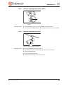
7.4.2
Hinged skylight
Z If it rains, the ventilation skylight position could lead to water entering the
living area. Therefore close hinged skylight completely.
1
Fig. 22
Securing knob at the hinged
skylight
Fig. 23
2
3
Hinged skylight, guide
The hinged skylight is opened on one side only.
Opening:
Press the safety knob (Fig. 22,2) and pull the bar (Fig. 22,1) down with both
hands.
Pull the bar (Fig. 23,1) in the guides (Fig. 23,2) to the rearmost position
(Fig. 23,3).
42
Motorhome - 02/11-0 - GLO-MJ11-00EN
Living
Closing:
7
Use both hands to push the bar (Fig. 23,1) slightly upwards.
Push the bar back in the guides.
Push the bar upwards with both hands until it is above the safety knob
(Fig. 22,2).
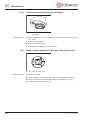
Fig. 24
Ventilation position
Hinged skylight in ventilation
position
Fig. 25
Locking mechanism in ventilation position
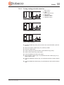
The hinged skylight can be put in two ventilation positions: Bad weather position (Fig. 24,1) and central position (Fig. 24,2). Depending on the model, the
skylight can be locked in the central position with the latch (Fig. 25,1).
Press the safety knob (Fig. 22,2) and pull the bar (Fig. 22,1) down with both
hands.
Pull the bar in the guides (Fig. 23,2) to the desired position.
Push the bar slightly upwards and into the selected guide (Fig. 24,1 or 2)
and lock if necessary.
Roman shade
Closing:
To close and open the Roman shade:
Pull out Roman shade at the handle and release in the required position.
The Roman shade will stay in that position.
Opening:
Insect screen
Closing:
Slowly push the Roman shade at the handle to its initial position.
To close and open the insect screen:
Pull the insect screen by the handle to the opposite handle of the Roman
shade.
Opening:
Motorhome - 02/11-0 - GLO-MJ11-00EN
Press the rear part of the handle of the insect screen. The latch is released.
Use handle to return the insect screen slowly to its initial position.
43
7
Living
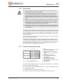
7.4.3
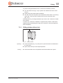
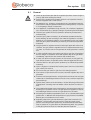
Wind-up skylight
Fig. 26
Wind-up skylight
The wind-up skylight can be opened using the manual crank.
Opening:
Rotate the hand crank (Fig. 26,2) until a resistance can be felt (max.
opening angle 70°).
Closing:
Rotate the hand crank until the wind-up skylight is closed. The wind-up sky-
light can be locked after rotating two or three more times.
Check the locking mechanism. To do so, press your hand against the
acrylic glass.
Roman shade
Closing:
The Roman shade can be closed in any position, as desired. If the Roman
shade is locked with the insect screen, the insect screen is also moved along
on closing the Roman shade.
Pull the handle of the Roman shade (Fig. 26,3) and release in the desired
position. The Roman shade will stay in that position.
Opening:
Insect screen
Closing:
Slowly push the Roman shade at the handle to its initial position.
If the insect screen is locked with the Roman shade, the Roman shade is also
moved along on closing the insect screen.
Pull insect screen at the handle (Fig. 26,1) to the opposite handle of the
Roman shade (Fig. 26,3) and allow to engage.
Opening:
Press the handle of the insect screen (Fig. 26,1) at the back upwards and
detach the insect screen from the Roman shade (Fig. 26,3).
Slowly push insect screen at the handle to its initial position.
44
Motorhome - 02/11-0 - GLO-MJ11-00EN
Living
7.4.4
7
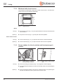
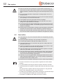
Multifunction skylight
Z Do not stand on the acrylic glass of the multifunction skylight.
Z Before commencing the journey, check that the multifunction skylight is
closed and locked.
Z The multifunction skylight is not to be opened or closed during the journey.
Z The multifunction skylight may only be handled with both hands on the
grips.
1
1 2 3
2
3 2 4
Fig. 27
Multifunction skylight
Fig. 28
Fig. 29
Positions of the multifunction skylight
Multifunction skylight blind
locking mechanism
The multifunction skylight can be opened in various positions.
Opening:
Grip one handle (Fig. 27,3) with one hand respectively and bring the multi-
function skylight into the desired position.
When the multifunction skylight is opened upwards, press the locks
(Fig. 27,2) and slide the multifunction skylight at the handles to the rear.
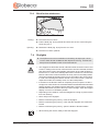
Blind
Closing:
To close and open the blind:
Press the red release knobs at the handle (Fig. 27,1) together and pull the
blind to the desired position using the handle.
Release the handle. The blind will stay in that position.
Opening:
Press the red release knobs at the handle (Fig. 27,1) together. The latch is
released.
Use handle to return the blind slowly to its initial position.
Motorhome - 02/11-0 - GLO-MJ11-00EN
45
7
Living
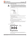
Roller insect screen
Closing:
To close and open the roller insect screen:
Pull the roller insect screen at the handle (Fig. 27,4) to the opposite handle
of the blind (Fig. 27,1) and allow to engage.
Opening:
Hold the roller insect screen at the handle (Fig. 28,2) and press the
unlocking bar (Fig. 28,1) at the handle. The lock is released.
Use handle to return the roller insect screen slowly to its initial position.
7.5
Rotating the seats
X Before starting the journey, rotate the seat in the direction of travel and
lock in position. The rotating seats must remain locked in the direction of
travel during the journey.
Z Chapter 5 describes the adjustment of the seat position and of the arm-
rests.
Z Move the seats all the way down before turning. Otherwise, the seats
cannot be turned.
Depending on the model, the lever for turning the seats is located at the front
of the seat or on the left or right side.
1
5
2
4
Fig. 30
Turning:
Driver's and front passenger's
seats (Aguti)
Fig. 31
3
Driver's and front passenger's
seats (ISRI)
Push the armrests at the driver's/front passenger's seat upward.
Push the driver's seat/front passenger's seat backwards or into the central
position.
Push or pull the lever (Fig. 30,3 or Fig. 31,4) to turn the seat. The seat is
released from the locking device.
The seats can be rotated in any direction. The seats can only be locked in position in the direction of travel.
46
Motorhome - 02/11-0 - GLO-MJ11-00EN
Living
7.6
7
Bench seat
1
2
3
Fig. 32
Bench seat extension
Increasing the seating area
Bench seat
The bench seat can be extended if required.
Z Do not pull at the cover (Fig. 32,1).
Pull out the extension at the handle (Fig. 32,2) under the cover.
Storage space
Opening the storage space
lid:
7.7
7.7.1
An additional storage space is located under the bench seat.
Open the storage space lid by pulling the latch (Fig. 32,3).
Tables
Suspension table with fold-out leg
3
1
2
Fig. 33
Suspension table with fold-out
leg
Fig. 34
Table top locking mechanism
The suspension table may also be used as a bed foundation.
Conversion to bed
foundation:
Slightly lift the front of the table-top.
Unlock the table leg (Fig. 33,2) at the hinge and fold it in.
Press the release knob (Fig. 34,1) at the locking mechanism of the table-
top.
Detach the suspension table from the upper attachment rail.
Motorhome - 02/11-0 - GLO-MJ11-00EN
47
7
Living
Attach suspension table to the lower attachment rail (Fig. 33,1) and rest it
onto the table leg hinge (Fig. 33,3).
Lock the table-top.
7.7.2
Suspension table with dismantable support leg
Variant 1
6
1
2
1
2
5
3
4
Fig. 35
Suspension table with dismantable support leg
Fig. 36
Bed extension (extra bed)
The table size can be enlarged by swiveling out a table-top extension.
Extending:
Pull the knob (Fig. 35,2) of the locking mechanism downward and swivel
out the table-top extension (Fig. 35,1).
Reducing size:
Swivel the table-top extension (Fig. 35,1) under the table-top (Fig. 35,6)
until the locking mechanism latches audibly.
The dismantable support leg enables the suspension table to be used as a bed
foundation.
Conversion to bed
foundation (extra bed):
Swivel out the table-top extension (Fig. 35,1).
Lift the front of the table-top (Fig. 35,6) by approx. 45°.
Pull out the lower part of the support leg (Fig. 35,4) down and lay aside.
Remove the table-top from its upper retainer.
Hook the table-top with the retainers at an angle of 45° into the lower
attachment rail (Fig. 35,3) and set it down onto the floor with the upper part
of the support leg (Fig. 35,5).
Lock the table-top.
Place the bed extension (Fig. 36,2) for the extra bed onto the table-top
extension (Fig. 36,1).
Conversion to bed
foundation (spare bed):
Turn the driver's seat and push it all the way forward.
Swivel out the table-top extension (Fig. 35,1).
Lift the front of the table-top (Fig. 35,6) by approx. 45°.
Pull out the lower part of the support leg (Fig. 35,4) down and lay aside.
Remove the table-top from its upper retainer.
Hook the table-top with the retainers at an angle of 45° into the lower
attachment rail (Fig. 35,3) and set it down onto the floor with the upper part
of the support leg (Fig. 35,5).
Lock the table-top.
48
Motorhome - 02/11-0 - GLO-MJ11-00EN
7
Living
Variant 2
1
2
6
1
5
4
2
Fig. 37
3
Suspension table
Fig. 38
Back cushion frame
The table size can be enlarged by inserting a table-top extension.
Extending:
Reducing size:
Turn open the locking screws (Fig. 37,4) and pull the table forwards.
Insert the table-top extension and tighten the locking screws (Fig. 37,4).
Remove the table-top extension and store it.
Turn open the locking screws (Fig. 37,4) and pull the table backwards.
The dismantable support leg enables the suspension table to be used as a bed
foundation.
Conversion to bed
foundation (extra bed):
Lift the front of the table-top by approx. 45°.
Turn open the locking screws (Fig. 37,4) and pull the table forwards.
Tighten the locking screws (Fig. 37,4).
Pull out the lower part of the support leg (Fig. 37,2) down and lay aside.
Remove the table-top from its upper retainer.
Hook the table-top with the retainers at an angle of 45° into the lower
attachment rail (Fig. 37,3) and set it down onto the floor with the upper part
of the support leg.
Lay the table-top extension between the table and wall.
Increase the seating area (see Section 7.6).
Slide the wedge (Fig. 37,1) for the seat extension between the cushions.
Undo the velcro at the back cushion (Fig. 37,6) behind the driver's seat.
Loosen the knurled screw (Fig. 38,1) from the back cushion frame and
slide the back cushion frame (Fig. 38,2) together. If necessary, slide the
driver's seat right to the front.
Lay the seat and back cushions (Fig. 37,5 and 6) together.
Place on the additional wedges.
Motorhome - 02/11-0 - GLO-MJ11-00EN
49
7
Living
7.7.3
Fixed table of the rear seating group
1
6
2
3
5
Fig. 39
4
Fixed table of the rear seating
group
The table-top of the fixed table of the rear seating group can be moved lengthways.
Shift the table-top:
Undo the knurled screw (Fig. 39,6).
Move the table-top (Fig. 39,1) to the desired position.
Retighten the knurled screws.
Conversion to bed
foundation:
Undo the knurled screw (Fig. 39,2).
Lift off the table-top (Fig. 39,1).
Undo the knurled screw (Fig. 39,4).
Turn the table leg (Fig. 39,3) out of the base holder (Fig. 39,5).
Store the table leg and the table-top behind the driver's seat.
Pull out the slatted frames at the bench seats about 50 cm.
Place the cushions.
50
Motorhome - 02/11-0 - GLO-MJ11-00EN
7
Living
7.7.4
Swivel table
The swivel table can be moved on rails or be removed completely. The tabletop of the swivel table can be swiveled into different positions.
1
1
2
5
4
Fig. 40
Install the swivel table:
3
2
Swivel table
Fig. 41
Table frame holder
Place the table frame in the holder (Fig. 41,2) and slide it to the desired
position.
Push the locking mechanism (Fig. 41,1) downwards.
Insert the table-top into the holder and secure with the knurled screw
Fig. 40,5).
Fasten the table-top with the lever screws (Fig. 40,3 and 4).
Swivelling the table-top:
Loosen the lever screws (Fig. 40,3 and 4).
Swivel table top (Fig. 40,1) into required position.
Retighten the lever screws (Fig. 40,3 and 4).
Removing the swivel table:
Loosen the knurled screw (Fig. 40,5).
Pull the table-top (Fig. 40,1) out of the holder.
Loosen the locking mechanism (Fig. 41,1) of the table frame.
Slide the table frame towards the holder (Fig. 41,2) and remove upwards.
Placing the swivel table
behind the seat:
Pull the table-top securing mechanism (Fig. 40,2) upwards and bring the
table-top (Fig. 40,1) into a vertical position.
Loosen the locking mechanism (Fig. 41,1) of the table frame.
Slide the swivel table on the rails completely to the left (behind the driver's
seat) or to the right (behind the front passenger's seat).
Push the locking mechanism (Fig. 41,1) of the table frame downwards.
Loosen the lever screws (Fig. 40,3 and 4).
Swivel table top (Fig. 40,1) into required position.
Retighten the lever screws (Fig. 40,3 and 4).
Motorhome - 02/11-0 - GLO-MJ11-00EN
51
7
Living
7.7.5
Folding table
6
5
4
3
2
1
Fig. 42
Folding table, folded in
Fig. 43
Folding table, table leg holder
The folding table can be used as a table or as an additional storage space outside the vehicle. When the side door is opened, the folding table can be
mounted onto the rear of the kitchen unit.
Setting up in the vehicle:
Loosen the securing strap (Fig. 42,2) (snap fastener).
Pull the table leg (Fig. 42,5) upwards out of the holders (Fig. 42,3).
Fold the table-top (Fig. 42,4) upwards and insert the table leg (Fig. 43,1)
into the holder (Fig. 43,2).
Setting up outside the
vehicle:
Loosen the securing strap (Fig. 42,2) (snap fastener).
Pull the table leg (Fig. 42,5) upwards out of the holders (Fig. 42,3).
Fold the table-top (Fig. 42,4) slightly upwards and slide to the back
(Fig. 42, arrow).
Slide the table-top into the holders on the rear of the kitchen unit (Fig. 42,1).
Insert the table leg (Fig. 43,1) into the holder (Fig. 43,2).
7.8
Lamps
X Bulbs and light fittings can be extremely hot.
X Let the bulbs and lamp holders cool down before touching them.
X When the light is switched on or is still hot, a safety distance of at least
30 cm to combustible material such as net curtains or curtains has to be
maintained. Fire hazard!
52
Motorhome - 02/11-0 - GLO-MJ11-00EN
Living
7.8.1
Halogen spotlight (movable)
Fig. 44
Turning spotlight:
7
Spotlight
Grasp the housing (Fig. 44,2) and turn it.
The housing can be turned in different directions:
z To the left and to the right
z Up and down
Shifting spotlight:
7.8.2
Grasp the holder (Fig. 44,1).
Push spotlight along the rail system to desired position.
Halogen spotlight
1
2
Fig. 45
Moving a halogen spotlight:
Halogen spotlight
Grasp the holder (Fig. 45,1) and turn it by 45°.
Remove the halogen spotlight (Fig. 45,2) from the rail system.
Insert the halogen spotlight (Fig. 45,2) at the desired position into the rail
system and turn by 45°.
Turn by 45° at the holder Fig. 45,1).
Motorhome - 02/11-0 - GLO-MJ11-00EN
53
7
Living
7.8.3
Lamp in pop-up roof
1
REMOTE
CONTROL
OFF
1
Fig. 46
Lamp in pop-up roof
Fig. 47
Switching on the light:
Push the switch (Fig. 46,1) to the left.
Switching the light off:
Push the switch (Fig. 46,1) to the middle.
Switching on and off with
the remote control:
7.9
7.9.1
Remote control for lamp in
pop-up roof
Push the switch (Fig. 46,1) to the right.
Press the button (Fig. 47,1) to switch the light on and off.
Beds
Fixed bed
X Do not let the slatted frame fall downwards during closing!
A storage compartment is underneath the bed. Depending on the model, fold
the slatted frame from the inside upwards or lift out of the latch or remove the
bulkheads in order to place items in the storage compartment or remove them.
Opening:
Closing:
54
Lift the mattress forwards and set it down on the panel.
Lift and hold the slatted frame.
Move the slatted frame downwards completely.
If necessary, push the mattress behind the panel.
Motorhome - 02/11-0 - GLO-MJ11-00EN
Living
Dismantling the fixed bed
7
In order to increase the storage compartment space the bed can also be dismantled and stored completely.
1
1
2
2
3
Fig. 48
Dismantling Variant 1:
Dismantling Variant 1
Fig. 49
Dismantling Variant 2
Z The first step of the stairs can be removed additionally in order to create a
passage.
Remove the middle cushion and middle board.
Remove the mattress.
Lift the slatted frame out of the latch and place it on the cover (Fig. 48,3).
Place the cushions, mattresses and slatted frames (Fig. 48,2) next to each
other.
Secure everything using the belt (Fig. 48,1).
Dismantling Variant 2:
Remove the mattress.
Lay the slatted frame together with the mattress on the cover.
Stack the cushions, mattresses and slatted frames (Fig. 49,2) onto each
other.
Secure everything using the belt (Fig. 49,1).
Enlarging the fixed bed
It is possible to connect two single beds into a double bed.
1
2
1
2
3
Fig. 50
Double bed rear
Fig. 51
Double bed stairs
Z In order to use the stairs do not use the board (Fig. 51,1) above the stairs
as well as the additional cushion (Fig. 50,3).
Motorhome - 02/11-0 - GLO-MJ11-00EN
55
7
Living
Connecting beds:
Lay the middle board between the two beds.
Lay the board (Fig. 51,1) onto the braces above the stairs (Fig. 51,2).
Insert the additional cushions (Fig. 50,1, 2 and 3).
7.9.2
Bed in the pop-up roof
X The maximum load for the bed in the pop-up roof amounts to 200 kg.
X Fold in the pop-up roof before commencing the journey.
X Only use the bed in the pop-up roof if the safety guards are in position.
X Never leave small children without supervision.
X Ensure in particular with regard to small children less than 6 years of
age, that they cannot fall out of the bed.
X Switch off the reading lamps in the pop-up roof when it is folded in. Fire
hazard!
Z Mount the safety guard when the persons are already in the pop-up roof.
1
1
2
2
Fig. 52
Opening:
Opening the pop-up roof
Fig. 53
Closing the pop-up roof
Loosen the safeguards (Fig. 52,2).
Press the locking mechanisms at the handles (Fig. 52,1) of the pop-up roof.
Use both hands to push the pop-up roof upwards.
Closing:
Z Before closing the pop-up roof open the doors of the vehicle. Material
damage may otherwise occur through excess pressure.
Open the doors of the vehicle.
Close the elastic bands in the pop-up roof so that the cloth bellows
(Fig. 53,2) are not clamped in.
Use the pulling devices (Fig. 53,1) to pull the pop-up roof downwards.
Pull the pop-up roof closed at the handles (Fig. 52,1) until the locking
mechanism latches in audibly.
X The locking mechanism of the pop-up roof must latch audibly into place.
56
Motorhome - 02/11-0 - GLO-MJ11-00EN
Living
7
Z When the pop-up roof is being folded in: Ensure that the safety guards and
the cloth bellows are not clamped in.
7.10
7.10.1
Converting seating groups for sleeping
Seating group rear
1 2
3
Fig. 54
2 1 12 4
3
42 1
1
2
3
4
5
Back cushion
Seat cushion
Table
Slatted frame
Extension at the slatted frame
Prior to conversion
1 2
2 1 12 45 54 2 1
45 54
Fig. 55
1
2
Fig. 56
During conversion
2
1
1
2
2
4
4
1
After conversion
Dismantle the table (Fig. 54,3) (see Section 7.7).
Pull out the slatted frames (Fig. 54,4).
Fold out the extension (Fig. 55,5) at the slatted frame.
Pull the seat cushions (Fig. 55,2) to the middle of the slatted frame.
Insert the back cushions (Fig. 55,1) between the seat cushions and the
exterior wall.
Z The formed cushion parts in the side panels can be removed to extend the
sleeping area.
Motorhome - 02/11-0 - GLO-MJ11-00EN
57
7
Living
7.10.2
Front seating group
1
2
3
4
5
Fig. 57
Prior to conversion
Fig. 58
After conversion
Back cushion
Seat cushion
Table
Driver's seat
Front passenger's seat
Turn the driver's seat (Fig. 57,4) so that the backrest faces the driver's
door.
Turn the front passenger's seat (Fig. 57,5) so that the backrest faces the
front passenger's door.
Convert the table (Fig. 57,3) to a bed foundation (see Section 7.7).
Pull the seat cushion (Fig. 58,2) on the table.
Place the back cushion (Fig. 58,1) on the bench seat.
Slide the front passenger's seat (Fig. 58,5) as far as possible to the driver's
side.
Slide the driver's seat (Fig. 58,4) as near as possible to the front pas-
senger's seat.
58
Motorhome - 02/11-0 - GLO-MJ11-00EN
Living
7.10.3
7
Facing seating unit with extension
3
2 1
3
4
Fig. 59
5
6
4
5
6
Back cushion
Seat cushion
Table
Bench seat extension
Seat cushion
Additional cushion
Additional cushion
Additional cushion
Prior to conversion
3
2 1
3
4
Fig. 60
2 1
1
2
3
4
5
6
7
8
2 1
4
During conversion
2
1
2
1
4
Fig. 61
After conversion
Extend the table (Fig. 59,3) and convert it into a bed foundation (see Sec-
tion 7.7).
Remove the back cushion (Fig. 59,1) and lay it aside.
Fold in the back frame.
Pull the handle and open the bench seat extension (Fig. 59,4).
Pull the seat cushion (Fig. 59,5) apart.
Insert the additional cushion (Fig. 59,6).
Place the back cushion (Fig. 61,1) between the seat cushion (Fig. 61,2)
and the driver's seat.
Insert the additional cushion (Fig. 61,7) between the back cushion and the
wall.
Insert the additional cushions (Fig. 61,8) between the seat cushion and the
wall.
Motorhome - 02/11-0 - GLO-MJ11-00EN
59
7
Living
7.10.4
Front seating group with extension
1 2
3
12
3
4
Fig. 62
1
2
3
4
5
6
7
Back cushion
Seat cushion
Table
Table-top extension
Bed extension
Additional cushion
Driver's seat
Prior to conversion
7
1 2
3
12
345
1 2
4
5
Fig. 63
3
12
34
7
23 4
7
4
During conversion (extra bed)
Fig. 64
During conversion
(spare bed)
7
1 2
Fig. 65
Variant 1 (extra bed):
6
1 2 3 4 56
After conversion (extra bed)
1
Fig. 66
23
1
After conversion (spare bed)
Extend the table (Fig. 62,3) and convert it into a bed foundation (see Sec-
tion 7.7).
Place the bed extension (Fig. 63,5) for the extra bed onto the table-top
extension (Fig. 63,4).
Place the additional cushion (Fig. 65,6) on the table and the bed extension.
Variant 2 (spare bed):
Turn the driver's seat (Fig. 64,7) and push it all the way forward.
Extend the table (Fig. 64,3) and convert it into a bed foundation (see
Section 7.7).
Reposition the back cushion (Fig. 64,1).
Place the seat cushion (Fig. 66,2) between the back cushion (Fig. 66,1)
and the driver's seat (Fig. 66,7).
60
Motorhome - 02/11-0 - GLO-MJ11-00EN
Gas system
8.1
8
General
8Gas system
X Close all gas isolator taps and the regulator tap before commencing the
journey and when leaving the vehicle.
X Closing of the isolator and regulator valves is not required at vehicles
that are equipped with a crash sensor.
X No appliance (e.g. heating or refrigerator) that is operated through the
built-in burner may be operational while fuel is being filled up, on ferries
or in the garage. Danger of explosion!
X If an appliance is operated through a burner, do not start the appliance
up in closed areas (e.g. garages). Danger of poisoning and suffocation!
X Have the gas system serviced, repaired or altered by an authorised
workshop only.
X Have the gas system checked by an authorised specialist workshop
before starting up and according to the national regulations. This also
applies for not registered vehicles. For modifications to the gas system
have the gas system immediately checked by an authorised specialist
workshop.
X The gas pressure regulator and the exhaust gas pipes also have to be
checked. The gas pressure regulator has to be replaced at least every
10 years. The vehicle owner is responsible for seeing that this is carried
out.
X In case of a defect of the gas system (gas odour, high gas consumption)
there is danger of explosion! Close the regulator tap on the gas bottle
immediately. Open doors and windows and ventilate well.
X In case of a defect in the gas system: Do not smoke; do not ignite any
open flames, and do not operate electric switches (light switches etc.).
X Have the defect in the gas system repaired by an authorised specialist
workshop.
X Open a skylight or a window before taking open sources of combustion
(gas cooker) into service.
X Do not use the gas cooker or gas oven for heating purposes.
X If the vehicle or gas devices are not used, close the regulator tap on the
gas bottle.
X If there are several gas devices, each gas device must have its own gas
isolator tap. If individual gas devices are not in use, close the respective
gas isolator tap.
X Ignition safety valves must close within 1 minute after the gas flame has
extinguished. A clicking sound is audible. Check function from time to
time.
X The installed gas appliances are designed for use solely with propane or
butane gas or a mixture of both. The gas pressure regulator as well as
all installed gas devices are set for a gas pressure of 30 mbar.
X Propane gas is capable of gasification up to -42 °C, whereas butane gas
gasifies at 0 °C. Below these temperatures no gas pressure is available.
Butane gas is unsuitable for use in winter.
X Regularly inspect the gas tube fitted to the gas bottle connection for
tightness. The gas tube must not have any tears and must not be
porous. Have the gas tube replaced by an authorised specialist workshop no later than 10 years after the manufacturing date. The operator
of the gas system must see to it that the parts are replaced.
Motorhome - 02/11-0 - GLO-MJ11-00EN
61
8
Gas system
X Due to its function and construction, the gas bottle compartment is a
space which is open to the exterior. Never cover or block the standard
forced ventilation. Otherwise leaking gas cannot be dispersed to the outside.
X Do not use the gas bottle compartment as storage space as it is not
moisture-proof.
X Secure the gas bottle compartment in order to prevent unauthorised per-
sons opening it. To do so lock the access.
X The regulator tap on the gas bottle must be accessible.
X Only connect gas-operated devices (e.g. gas grill) which have been
designed for a gas pressure of 30 mbar.
X The exhaust gas pipe must be fitted tightly to the heating system and to
the vent and must be sealed. The exhaust gas pipe must not show any
evidence of damage.
X Exhaust fumes must be able to escape into the atmosphere unhindered
and fresh air must be able to enter unhindered. Therefore keep the
waste gas vents and intake openings clean and free (e.g. of snow and
ice). No snow walls or aprons may be allowed to lie against the vehicle.
8.2
Gas bottles
X Gas bottles are only to be transported within the designated gas bottle
compartment.
X Place gas bottles vertically in the gas bottle compartment.
X Tie down gas bottles so that they are unable to turn or tilt.
X If the gas bottles are not connected to the gas tube, always place the
protective cap on top.
X Close the regulator tap on the gas bottle before the gas pressure regu-
lator or gas tube are removed from the gas bottle.
X Use your hands only to connect the gas pressure regulator or the gas
tube to the gas bottles. Do not use any tools.
X Only use special gas pressure regulators with a safety valve designed
for vehicle use. Other gas pressure regulators are not permitted and
cannot meet the demanding requirements.
X Use only 11 kg or 5 kg gas bottles. Camping gas bottles with a built-in
reflux valve (blue bottle with max. 2.5 or 3 kg content) are permitted in
exceptional cases with a safety valve.
X Never block the ventilation openings in the floor under the gas bottles.
Z Screwed connections on the gas pressure regulator have left-handed
threads.
Z For gas-operated units the gas pressure must be reduced to 30 mbar.
Z Connect gas pressure regulator complete with safety valve directly to bottle
valve.
The gas pressure regulator reduces the gas pressure in the gas bottle
down to the operating pressure of the gas devices.
Z For filling and connecting the gas bottles in Europe the accessories shops
have corresponding Euro filling sets and Euro bottle sets.
Z Information is available at the dealers and service centres.
62
Motorhome - 02/11-0 - GLO-MJ11-00EN
Gas system
8.3
8
Changing gas bottles
X When changing gas bottles, do not smoke or create any open fire.
X When you have changed the gas bottle, check whether gas escapes at
the connection points and unions. Use a leakage search spray to spray
the relevant connection point or union. These agents are available at the
accessories shop.
Fig. 67
Gas bottle connection
Open flap for the gas bottle compartment.
Close the regulator tap (Fig. 67,4) on the gas bottle. Pay attention to the
direction of the arrow.
Hold the gas pressure regulator (Fig. 67,2) and open the knurled nut
(Fig. 67,3) (left-handed thread).
Remove the gas pressure regulator and the gas tube (Fig. 67,1) from the
gas bottle.
Release the fixing belts and remove the gas bottle.
Place a filled gas bottle in the gas bottle compartment.
Fix gas bottle in place with the fixing belts.
Position the gas pressure regulator (Fig. 67,2) and the gas tube (Fig. 67,1)
on the gas bottle and tighten the knurled nut (Fig. 67,3) by hand (lefthanded thread).
Close flap.
8.4
Gas isolator taps
3
Fig. 68
2
1
1
2
3
Cooker
Refrigerator
Heater/boiler
Symbols for the gas isolator
taps
A gas isolator tap (Fig. 68) for every gas device is built into the vehicle.
The gas isolator taps are located in the vehicle at different positions, and can
also be fitted separately.
Motorhome - 02/11-0 - GLO-MJ11-00EN
63
8
Gas system
8.5
Hose break guard (crash sensor)
Z If the vehicle is equipped with a crash sensor, the living area heater may
be operated during the journey.
Z Additionally observe the manufacturer's instruction manual.
The crash sensor (Fig. 69) protects against unwanted gas discharge. In the
event of an accident or a too high angle of the vehicle the gas supply will automatically be interrupted.
1
2
Fig. 69
Crash sensor
If the crash sensor has been triggered, it has to be released manually.
Releasing:
Use a pen or similar implement (Fig. 69,2) to press the release knob
(Fig. 69,1) in for several seconds.
64
Motorhome - 02/11-0 - GLO-MJ11-00EN
Gas system
8.6
8
DuoControl switching facility
X Do not use the switching facility in closed spaces.
Z If the vehicle is equipped with a panel of the DT series and the switching
facility is operated via this panel, the operating unit is not required.
Z Additionally observe the manufacturer's instruction manual.
The DuoControl is an automatic switching facility with a remote display for a
two-bottle gas system. The DuoControl switching facility automatically
switches gas supply from the primary bottle to the reserve bottle as soon as
the primary bottle is either empty or no longer ready for operation. The gas
appliances may still continue operation. The DuoControl switching facility is
suitable for all commercial gas bottles from 3 kg to 33 kg.
Fig. 70
Construction of the unit
DuoControl switching facility
Fig. 71
Operating unit
The DuoControl switching facility consists of a switching valve (Fig. 70,3) and
the operating unit (Fig. 71). The switching valve is mounted between the gas
tubes (Fig. 70,2 and 5). The knob (Fig. 70,4) on the switching valve is used to
select which of the gas bottles is to be used as a primary bottle and which is
to be used as a reserve bottle.
The switching valve is equipped with the regulator defroster "Eis-Ex". This prevents damage to the gas system during the winter months.
Only the electrical functions can be switched at the operating unit (Fig. 71).
The regulator taps on the gas bottles (Fig. 70,1 and 6) must be opened manually.
The switching valve provides a constant gas pressure, regardless of which gas
bottle is being drawn upon. The two indicator lamps on the operating unit show
the filling level of the primary bottle. The primary bottle is full when the green
indicator lamp (Fig. 71,6) lights up. The primary bottle is empty when the red
indicator lamp (Fig. 71,5) lights up. The gas is then supplied via the reserve
bottle.
Operating modes
Motorhome - 02/11-0 - GLO-MJ11-00EN
The DuoControl switching facility has two operating modes:
z Winter operation "On and heating"
z Summer operation "On"
65
8
Gas system
Putting into operation:
Open the regulator taps on the gas bottles (Fig. 70,1 and 6).
Use the knob (Fig. 70,4) on the switching valve (Fig. 70,3) to select the gas
bottle which is to be the primary source of gas (primary bottle).
Always turn the knob as far as it will go.
Switch on the DuoControl switching facility at the operating unit (Fig. 71).
To do so, set the rocker switch (Fig. 71,7) to winter operation "On and
heating" (Fig. 71,2) or to summer operation "On" (Fig. 71,4). The switching
valve is now vented. The yellow indicator lamp (Fig. 71,1) lights up when
winter operation has been selected and the regulator defroster is switched
on.
Switching off:
Set the rocker switch (Fig. 71,7) to " " (Fig. 71,3). The yellow indicator
lamp (Fig. 71,1) goes out.
Close the regulator taps on the gas bottles (Fig. 70,1 and 6).
Remote display
Changing gas bottles
The indicator lamps on the operating unit (Fig. 71,5 and 6) indicate in the
vehicle interior whether the primary bottle is ready for operation.
If the green indicator lamp (Fig. 71,6) goes out during operation and the red
indicator lamp (Fig. 71,5) lights up, the gas bottle selected as the primary
bottle is empty and has to be changed. The reserve bottle continues supplying
the gas appliances with gas.
X When changing gas bottles, do not smoke or create any open fire.
Changing gas bottles:
Close the regulator tap on the empty gas bottle.
Unscrew the gas tube from the gas bottle.
Connect the full gas bottle to the gas tube.
Open the regulator tap on the gas bottle.
Set the knob on the switching valve with half a turn, so that the newly
replaced gas bottle will serve as a reserve bottle.
66
Motorhome - 02/11-0 - GLO-MJ11-00EN
Electrical system
9.1
General safety instructions
9
9Electrical system
X Only allow qualified personnel to work on the electrical system.
X All electronic devices (e.g. mobile telephones, radios, televisions or DVD
players) which have been retrofitted to the vehicle and are operated
during the journey must have specific features: These are the CE certification, the EMC test (electromagnetic compatibility) and the "E1"
inspection.
Only in this way can the functional reliability of the vehicle be ensured.
Otherwise the airbag may be triggered or interference to the on-board
electronics may result.
The vehicle is a safe place during a storm (Faraday cage). However, to protect
the electrical devices, disconnect the 230 V connection and retract the
antennae as a precaution.
9.2
12 V power supply
Z To disconnect all electrical 12 V appliances from the power supply, discon-
nect the living area battery from the 12 V power supply. Depending on the
model, either press the switch on the transformer/rectifier or activate the
battery separation on the panel to do so.
When the vehicle is not connected to the 230 V power supply or the 230 V
power supply is switched off, the living area battery supplies the living area
with 12 VDC. The living area battery has a limited power supply only. For this
reason, electrical appliances such as the radio and the lights should not be
operated for a long time without using the 230 V power supply.
The 12 V power supply can be cut off with the 12 V main switch on the panel.
The heater and the electrical entrance step remain ready for operation.
When the vehicle engine is running, the vehicle alternator recharges the living
area battery and the starter battery.
Absorption refrigerator
Compressor refrigerator
9.2.1
The refrigerator is then only operated with 12 V if the vehicle engine is running.
This helps to prevent the living area battery from being run down too quickly.
The refrigerator is only operated with 12 V.
Living area battery
Z Prior to commencing a journey ensure the living area battery is fully
charged. For this reason charge the battery for at least 20 hours before
commencing the journey.
Z During the trip, use every opportunity to charge the living area battery.
Z Charge the living area battery for at least 20 hours after the journey.
Z Charge the battery for at least 20 hours before laying up.
Z Longer total discharge damages the battery irreparably.
Z Use only the installed transformer/rectifier to charge the living area battery.
Z Irreparable damage to the living area battery will result if it is overcharged.
Z For long periods of inactivity (4 weeks or more), either disconnect the living
area battery from the 12 V power supply or recharge it regularly.
Z Do not use the ignition when the starter battery or the living area battery is
disconnected. Danger of short circuit!
Motorhome - 02/11-0 - GLO-MJ11-00EN
67
9
Electrical system
Z The battery is maintenance-free. Maintenance-free means:
It is not necessary to check the acid level.
It is not necessary to lubricate the battery poles.
It is not necessary to refill the distilled water.
Even a maintenance-free battery must be charged regularly.
The charging condition of the living area battery can be read off on the panel.
Location
Depending on the model, the living area battery is installed under the driver's
seat or the front passenger's seat in the seat console.
Charging using a 230 V
power supply
If the vehicle is connected to the 230 V power supply, the living area battery
and the starter battery are automatically charged by the charger module on the
transformer/rectifier. The starter battery is charged with a float charge of 2 A.
The charging current is adapted to suit the charging condition of the battery.
This ensures that it is not possible to overload the battery.
To make use of the maximum output from the charger module on the transformer/rectifier, switch off all electrical appliances during charging.
Charging using the
vehicle engine
Changing
When the vehicle engine is running, the vehicle alternator recharges the living
area battery and the starter battery. When the vehicle engine is switched off,
the batteries are automatically disconnected from one another by a relay in the
transformer/rectifier. This prevents the starter battery from being run down by
electrical appliances in the living area. The starting capability of the vehicle is
thus preserved. The charging condition of the living area battery or the starter
battery can be read on the panel.
Z When the living area battery is changed, only use batteries of the same
type.
Z When changing the living area battery, use only batteries which meet the
minimum capacity of the charger. Observe the separate instruction manual
for the charger. Lower-capacity batteries will generate a great deal of heat
when they are charged. Danger of explosion!
Z Do not connect the battery cables to the wrong poles.
Z Do not use the ignition when the starter battery or the living area battery is
disconnected. Danger of short circuit!
Z Before disconnecting or connecting the terminals of the battery, switch off
the vehicle engine, the 230 V and 12 V power supplies as well as all the
appliances. Danger of short circuit!
To change the living area battery, proceed as follows:
Switch off the vehicle engine.
Switch off the 12 V main switch on the panel. The indicator lamp goes out.
Switch the battery cut-off switch on the transformer/rectifier to "Batterie
Aus" ("battery Off").
Disconnect the mains plug from the transformer/rectifier.
Switch off all gas appliances, all gas isolator taps and close the regulator
tap on the gas bottle.
There is a danger of short circuit when disconnecting the battery poles. For
this reason, first disconnect the negative pole on the living area battery and
then the positive.
68
Motorhome - 02/11-0 - GLO-MJ11-00EN
Electrical system
9
Remove the living area battery from the vehicle.
Install the new living area battery in the reverse order.
9.3
Transformer/rectifier (EBL 99)
Z Do not cover the ventilation slots. Danger of overheating!
Z Depending on the model, not all fuse slots are fitted with fuses.
Z Further information can be obtained in the manufacturer's instruction
manual.
Fig. 72
1
2
3
4
5
6
7
8
9
10
11
12
Motorhome - 02/11-0 - GLO-MJ11-00EN
Transformer/rectifier (EBL 99)
Main supply socket 230 V~
Output: Block 1 - refrigerator
Input: Block 2 - control lines, generator D+
Output: Block 4 - heater, safety/drainage valve, basic light (lighting in the entrance
area), entrance step
Output: Block 3 - panel
Output: Block 5 - solar cell (if fitted), spare 2, spare 3, spare 4
Output: Block 6 - solar charge regulator (if fitted)
Output: Block 7 - auxiliary charging unit
Output: Block 8 - consumer circuit 1, consumer circuit 2, TV, water pump, spare 1,
spare 5, spare 6
Battery selector switch ("Blei-Säure/Blei-Gel" (lead acid/dryfill))
Fuses
Battery cut-off switch ("Batterie Ein/Aus" ("battery On/Off"))
69
9
Electrical system
Functions
The transformer/rectifier has the following functions:
z The transformer/rectifier charges the living area battery. The transformer/
rectifier charges the starter battery with a float charge only.
z The transformer/rectifier monitors the voltage in the living area battery.
z The transformer/rectifier distributes the current to the 12 V circuits and
secures them. Devices with a maximum of 10 A can be connected to the
sockets.
z The transformer/rectifier contains connections for a solar charge regulator,
an auxiliary charging unit as well as other control and monitoring functions.
z When the engine is turned off, the transformer/rectifier separates the
starter battery electrically from the living area battery. This prevents the 12
V living area appliances from discharging the starter battery.
The transformer/rectifier only works in conjunction with a panel.
When the transformer/rectifier is subject to a heavy load, the fitted charger
module reduces the charging current. This protects the charging device
against overheating. The transformer/rectifier is subject to a heavy load when
e.g. an empty living area battery is charged, additional electrical appliances
are turned on and the ambient temperatures are high.
Location
9.3.1
Depending on the model, the transformer/rectifier is located in the seat console under the driver's seat or the front passenger's seat.
Battery cut-off switch
Z When the battery cut-off switch is OFF, the safety/drainage valve opens.
The water flows out of the boiler. When the battery cut-off switch has been
switched on again, close the safety/drainage valve of the boiler by hand.
Z After the battery cut-off switch has been switched on again: Switch the
basic light (lighting in the entrance area), entrance step, heater and
Reserve 4 back on (depending on the model) by switching the 12 V main
switch on briefly. This also applies if the living room battery was disconnected and then reconnected.
The battery cut-off switch switches off all the living area 12 V appliances,
including even the safety/drainage valve. This prevents the living area battery
from slowly discharging if the vehicle is not used for a longer period of time
(e.g. temporary lay-up).
The batteries can still be charged by the transformer/rectifier even when the
battery cut-off switch is switched off.
Switching on/off:
70
Press top of battery cut-off switch: Battery on.
Press bottom of battery cut-off switch: Battery off.
Motorhome - 02/11-0 - GLO-MJ11-00EN
Electrical system
9.3.2
9
Battery monitoring
Z Completely recharge a discharged living area battery as soon as possible.
The battery monitoring in the transformer/rectifier monitors the voltage in the
living area battery.
If the battery voltage falls below 10.5 V, the battery monitor in the transformer/
rectifier switches off all of the 12-V appliances, excluding the safety/drainage
valve.
Measures:
Switch off all the electrical appliances that are not essential at the corre-
sponding switch.
If necessary, use the 12 V main switch to switch the 12 V power supply
back on briefly. This is only possible, however, if the battery voltage lies
above 11 V. If the voltage is below this level, the 12-V power supply cannot
be switched on again until the living area battery has been recharged.
9.3.3
Charging the battery
When the vehicle engine is running, the vehicle alternator recharges the living
area battery and the starter battery. When the vehicle engine is switched off,
the batteries are automatically disconnected from one another by a relay in the
transformer/rectifier. This prevents the starter battery from being run down by
electrical appliances in the living area. The starting capability of the vehicle is
thus preserved. The charging condition of the living area battery or the starter
battery can be read on the panel.
If the vehicle is connected to the 230 V power supply, the living area battery
and the starter battery are automatically charged by the charger module on the
transformer/rectifier. The starter battery is charged with a float charge of 2 A.
The charging current is adapted to suit the charging condition of the battery.
This ensures that it is not possible to overload the battery.
To make use of the maximum output from the charger module on the transformer/rectifier, switch off all electrical appliances during charging.
9.4
Panel LT 410
1 2 3
4
230V
12,7
5
13,0 > 13,5 V
6
100%
75%
12,5
50%
12,2
12,0
1
2
3
4
25%
11,5
11,0
5
6
On
Off
12V
7
8
Fig. 73
Motorhome - 02/11-0 - GLO-MJ11-00EN
7
8
ALARM warning light for the living
area battery
230 V indicator lamp
Display V
Rocker switch for reading the battery
voltage of the starter and living area
batteries
Display for tank fill level
Rocker switch for reading the level in
the water or waste water tanks
Indicator lamp for the 12 V power
supply for the living area
12 V main switch
Panel LT 410
71
9
Electrical system
9.4.1
Battery voltage
V/tank gauge for battery voltage and water or waste water
levels
The V/tank gauge is for the indication of the battery voltage of the starter battery or the living area battery.
The LEDs of the display V (Fig. 73,3) displays the battery voltage.
Displays:
Press the upper part of the rocker switch (Fig. 73,4) "
": The battery
voltage of the starter battery is displayed.
Press the lower part of the rocker switch (Fig. 73,4) "
": The battery
voltage of the living area battery is displayed.
Volume of water/waste
water
The V/tank gauge is for the indication of the quantity of water or waste water.
Two LEDs each of the display Tank (Fig. 73,5) displays the filling level.
Z Only call up the tank level briefly. Calling up and displaying for a long time
can damage the transducers.
Displays:
Press the upper part of the rocker switch (Fig. 73,6) "
": The volume of
water is displayed.
Press the lower part of the rocker switch (Fig. 73,6) "
": The volume of
waste water is displayed.
9.4.2
Battery alarm for the living area battery
The red ALARM warning light (Fig. 73,1) flashes as soon as the voltage of the
living area battery falls below 11 V (measured under operation) and there is a
risk of a total discharge.
Z When the battery alarm comes on, switch off the appliances and charge the
living area battery, either by driving or by connection to a 230 V power
supply.
Z Total discharge damages the battery.
Z If the battery voltage falls below 10.5 V, the battery monitor in the trans-
former/rectifier switches off all of the 12 V appliances, excluding the safety/
drainage valve.
9.4.3
12 V main switch
The 12 V main switch (Fig. 73,8) switches the panel and the 12 V power
supply of the living area on and off.
Exception: Depending on the model. the safety/drainage valve, heater, basic
light (lighting in the entrance area), entrance step and Reserve 4 remain ready
for operation.
Switching on:
Press the upper part of the rocker switch (Fig. 73,8) "On": The 12 V living
area power supply is switched on. The indicator lamp (Fig. 73,7) lights up
green.
Switching off:
Press the lower part of the rocker switch (Fig. 73,8) "Off": The 12 V living
area power supply is switched off. The indicator lamp (Fig. 73,7) goes out.
72
Motorhome - 02/11-0 - GLO-MJ11-00EN
Electrical system
9
Z When leaving the vehicle switch off the 12 V main switch. This prevents
unnecessary discharging of the living area battery.
Z Appliances such as the safety/drainage valve, charger, solar charge regu-
lator and panel consume approx. 20 mA to 65 mA of electricity from the
battery capacity, even when the 12 V main switch is turned off. Therefore
disconnect the living area battery from the 12 V power supply, if the vehicle
will not be used for a long period of time.
9.4.4
12 V indicator lamp
The 12 V indicator lamp (Fig. 73,7) illuminates whenever the 12 V main switch
(Fig. 73,8) is switched on.
9.4.5
230 V indicator lamp
The yellow 230 V indicator lamp (Fig. 73,2) lights up whenever line voltage is
available at the transformer/rectifier input.
9.5
230 V power supply
X Only allow qualified personnel to work on the electrical system.
The 230 V power supply provides electricity for:
z Sockets with earth contact for appliances with maximum 16 A
z Refrigerator
z transformer/rectifier
The electrical appliances connected to the 12 V power supply of the living area
are supplied with voltage by the living area battery.
Connect the vehicle to an external 230 V power supply system as often as
possible. The charger module in the transformer/rectifier automatically
charges the living area battery. In addition to this, the starter battery is charged
with a float charge of 2 A.
9.5.1
230 V connection
X The external 230 V power supply must be protected by fuse with a fault
current protection switch (FI-switches, 30 mA).
X Completely unwind the cable on cable drums to prevent overheating.
Z For the connection points on camp sites (camping distributors) highly sen-
sitive fault current protection switches (FI-switches, 30 mA) are obligatory.
The vehicle can be connected to an external 230 V power supply. The cable
may have a length of maximum 25 m.
Depending on the model, the flap for the 230 V connection is identified with the
symbol " ".
Motorhome - 02/11-0 - GLO-MJ11-00EN
73
9
Electrical system
Connecting the power
cable:
Open the external flap.
Depending on the model, fold up the cover.
Plug in the plug:
Z Depending on the model, unlock the plug before pulling it out.
9.6
Fuses
X Only replace defective fuses when the cause of the defect is known and
has been remedied.
X Only replace defective fuses when the power supply is switched off.
X Never bridge or repair fuses.
9.6.1
Location
Main fuse
The main fuse has been fitted in the B-pillar (centre pillar). It can be accessed
from the passenger side.
1
2
1
2
Fig. 74
9.6.2
Main fuse 50 A/red
2 x flat fuse 2 A/grey
Main fuse
12 V fuses
The appliances connected to the 12 V power supply in the living area are fused
individually. The fuses are accessible at different positions in the vehicle.
1
2
Fig. 75
Unbroken fuse element
Broken fuse element
12 V fuse
An intact 12 V fuse can be detected by the unbroken fuse element (Fig. 75,1).
If the fuse element is broken (Fig. 75,2), change the fuse.
74
Motorhome - 02/11-0 - GLO-MJ11-00EN
Electrical system
9
Before changing fuses, take the function, value and colour of the relevant
fuses from the following specifications. When changing fuses, only use flat
fuses with the values shown below.
Fuses on the starter
battery
Depending on the model the fuses are installed near the starter battery under
a covering between the seats or in a seat console.
1
2
3
1
2
40
40
Fig. 76
Fuses on the living area
battery
3
20
20
Flat fuse 2 A/grey
(for alternator D+)
Jumbo flat fuse 40 A/orange
Flat fuse 20 A/yellow
(for refrigerator and charging line)
Fuses on the starter battery
The fuses are fitted next to the living area battery.
1
2
40
40
Jumbo flat fuse 40 A/orange
Flat fuse 2 A/grey
(for battery charger sensor)
1
2
Fig. 77
Fuse for the Thetford
toilet (swivel toilet)
Fuses on the living area battery
The fuse is located in the locker wall of the Thetford cassette.
1
Fig. 78
Changing:
Flat fuse 3 A/purple
Fuse for the Thetford toilet
Open the flap for the Thetford cassette on the outside of the vehicle.
Pull out the Thetford cassette completely.
Replace the fuse (Fig. 78,1).
Motorhome - 02/11-0 - GLO-MJ11-00EN
75
9
Electrical system
Function
Fuses at the
transformer/rectifier
EBL 99
Internal charger module
20 A yellow
Compressor refrigerator/AES refrigerator
20 A yellow
Heater
10 A red
Basic light/entrance step electrical
25 A white
Reserve 4
–
Reserve 3
–
Reserve 2
–
Reserve 1
15 A blue
Solar
15 A blue
Reserve 5
–
Reserve 6
–
Auxiliary charging unit
9.6.3
Value/colour
20 A yellow
Circuit 1
10 A red
Circuit 2
10 A red
TV
10 A red
Water pump
5 A beige
230 V fuse
Z The 230 V automatic circuit breaker is always mounted near the 230 V con-
nection.
Fig. 79
230 V automatic circuit breaker
The 230 V connection is protected by a two-pole automatic circuit breaker
(Fig. 79,1).
Location
76
The automatic circuit breaker is in the wardrobe or under a cover in the rear
area (under the slatted frame), depending on the model.
Motorhome - 02/11-0 - GLO-MJ11-00EN
Appliances
10.1
General
10
10Appliances
Z The heat exchanger of the Truma hot-air heater has to be replaced after
30 years. Only the manufacturer of the heater or an authorised specialist
workshop is allowed to replace the heat exchanger. The operator of the
heater must see to it that the parts are replaced.
Z For safety reasons, spare parts for pieces of heating appliances must cor-
respond with manufacturer's instructions and be permitted by the manufacturer as a spare part. These spare parts may only be fitted by the
manufacturer or an authorised specialist workshop.
Z Further information can be obtained in the instruction manual for the
respective appliance.
The appliances heater, boiler, cooker and refrigerator are fitted depending on
the model of the vehicle.
In this instruction manual a description is given only for the operation of the
appliances and their particular features.
To operate gas appliances, first open the regulator tap on the gas bottle and
the gas isolator tap corresponding to the appliance.
3
Fig. 80
10.2
2
1
1
2
3
Cooker
Refrigerator
Heater/boiler
Symbols for the gas isolator
taps
Heater
X Never let gas escape unburned due to danger of explosion.
X Never run the heater in gas operation when filling the fuel tank, on ferries
or in the garage. Danger of explosion!
X Never operate the heater in gas operation in closed rooms (e.g.
garages). Danger of poisoning and suffocation!
Z The circulation fan is automatically switched on when the hot-air heater is
activated. During operation it is switched off and back on automatically by
a thermostat control unit. This puts an immense strain on the living area
battery, if the vehicle is not connected to an external 230 V power supply.
Take into consideration that the living area battery only has limited
reserves of energy.
Start-up
Motorhome - 02/11-0 - GLO-MJ11-00EN
When lighting the heater for the first time a small amount of smoke and odour
will occur. Immediately set the operating switch of the heater to its highest
position. Open doors and windows and ventilate well. Smoke and odour will
disappear by themselves after a while.
77
10
Appliances
10.2.1
To heat properly
Fig. 81
Hot air distribution
Adjusting the air outlet
nozzles
Air outlet nozzle
Several air outlet nozzles (Fig. 81) are built into the vehicle. Pipes conduct the
warm air to the air outlet nozzles. Turn the air outlet nozzles in a suitable position so the air can escape as required. To avoid draft close the air outlet nozzles on the dashboard and set the air distribution of the base vehicle to air
circulation.
z Fully open: Full hot air stream
z Half or partially open: Reduced hot air stream
When five air outlet nozzles are completely opened, less warm air escapes
through each nozzle. However, if only three air outlet nozzles are opened,
more warm air flows out of each nozzle.
10.2.2
Truma Combi hot-air heater
Z Empty the complete heating system when the heater is out of operation
due to risk of frost.
Z Do not use the space above and behind the heater as a storage compart-
ment.
1
2
Combi
3
2
2
5
4
1
8
Fig. 82
Operating modes
1
3
4
5
6
7
Operating unit for heater/boiler
3
4
5
6
7
8
Temperature control knob
Summer operation water temperature 40 °C or 60 °C
Rotary switch
Off
Winter operation "Heater without
boiler"
Winter operation "Heater and boiler"
Indicator lamp green:
Lights up = "Heater operation"
Flashes = "Delayed shut-off for appliance temperature reduction is active"
Indicator lamp yellow/red:
Lights up yellow = "Boiler heating-up
phase"
Flashes/lights up red = "Fault"
The heater has two operating modes:
z Winter operation
z Summer operation
It is only possible to heat the vehicle in the "Winter" operating mode. With the
"Summer" operating mode only water in the boiler is heated. It is not possible
to heat the vehicle in this operating mode.
78
Motorhome - 02/11-0 - GLO-MJ11-00EN
Appliances
Selecting operating mode:
10
Set the operating mode using the rotary switch (Fig. 82,3).
The power supply of the heater cannot be interrupted by means of the 12 V
main switch.
Winter operation
Switching on:
The heater selects the required burner setting according to the set heating
level. In the "Heater and boiler" operating mode (Fig. 82,6) the water in the
boiler is also heated. The heater can be operated with an empty boiler in the
"Heater without boiler" operating mode (Fig. 82,5).
Open the regulator tap on the gas bottle and the gas isolator tap "Heater/
boiler".
Set the temperature control knob (Fig. 82,1) at the operating unit to the
desired heating level.
Set the rotary switch (Fig. 82,3) to winter operation "Heater without boiler"
(Fig. 82,5) or to winter operation "Heater and boiler" (Fig. 82,6).
Green indicator lamp (Fig. 82,7) lights up.
The circulation fan automatically switches on when the heater is activated.
Switching off:
Set the rotary switch (Fig. 82,3) to " " (Fig. 82,4).
Close the gas isolator tap "Heater/Boiler" and the main regulator tap on the
gas bottle.
After switching off the heater, the circulation fan may still run for a moment to
use up the residual heat.
Summer operation
It is not possible to heat the vehicle in the "Summer" operating mode. In this
operating mode only the water in the boiler is heated.
Z Further information can be obtained from the separate instruction manual
"Gas heater".
Z For further information about the use of the boiler see Section "Boiler".
Motorhome - 02/11-0 - GLO-MJ11-00EN
79
10
Appliances
Variant: Heater with gas
and 230 V electrical
operation
Z 230 V electrical operation is only possible when the vehicle is connected to
the 230 V power supply.
Z Select the output level for 230 V electrical operation so that it corresponds
to the fuse protection of the 230 V connection (900 W for 3.9 A fuse, 1800
W for 7.8 A fuse).
Z If the heater is set at the operating unit to "Summer" operation and the
energy selector switch is set to mixed operation, the heater nevertheless
operates only in 230 V operation. The gas burner is not switched on.
1
2
3
4
5
6
Fig. 83
230 V electrical operation (1800 W)
230 V electrical operation (900 W)
Gas operation
Gas operation and 230 V electrical
operation (900 W)
Gas operation and 230 V electrical
operation (1800 W)
Yellow indicator lamp "230 V electrical operation"
Energy selector switch for
heater/boiler
The heater can be operated with different types of energy:
z Gas operation (Fig. 83,3)
z 230 V electrical operation with the output levels 900 W (Fig. 83,2) or
1800 W (Fig. 83,1)
z Gas operation and 230 V electrical operation (mixed operation) with the
output levels 900 W (Fig. 83,4) or 1800 W (Fig. 83,5)
The combination gas operation and 230 V electrical operation reduces the
heating-up time (only possible when the heater on the operating unit (Fig. 82)
is set to winter operation).
When 230 V electrical operation has been selected, the yellow indicator lamp
(Fig. 83,6) lights up.
Z Further information can be obtained from the separate instruction manual
"Gas heater".
Z For further information about the use of the boiler see Section "Boiler".
80
Motorhome - 02/11-0 - GLO-MJ11-00EN
Appliances
10.2.3
10
Heater for waste water tank and waste water pipes (winter
comfort package)
In order to prevent waste water fittings freezing up, the waste water tank and
the waste water pipes can be electrically heated separately.
When the heater is turned on, temperature sensors monitor the temperature
of the waste water tank and the waste water pipes. If the temperature falls
below 5 °C, the heating elements are switched on and the waste water tank
and waste water pipes are heated. If the temperature rises above a certain
level, the heating elements are switched off again.
3
2
Combi
1
5
4
HORN
1
123
Fig. 84
Control unit
Fig. 85
Switch indicator lamps
The control unit (Fig. 84) is installed under the bench seat. The control lamps
on the control unit have the following meanings:
z Indicator lamp (Fig. 84,2) lights up in green: Regulation in operation.
z Indicator lamp (Fig. 84,1) lights up in red: Waste water tank is heated.
z Indicator lamp (Fig. 84,3) lights up in red: Waste water pipes are heated.
The on/off switch (Fig. 85,1) is installed on the panel under the sink. Press the
switch up to switch on, press it down to switch off.
10.3
Boiler
X Never let gas escape unburned due to danger of explosion.
X When filling the fuel tank, on ferries or in the garage, never run the boiler
in gas operation. Danger of explosion!
X Never operate the boiler in gas operation in closed rooms (e.g. garages).
Danger of poisoning and suffocation!
X The water in the boiler can be heated up to 60 °C. Risk of scalding!
Z Never use boiler when empty.
Z If the boiler is not being used, empty it if there is any risk of frost.
Z Only operate the boiler with the maximum temperature setting if you
require a large quantity of warm water. This protects the boiler against the
build-up of limescale.
Z Do not use the water from the boiler as drinking water.
Motorhome - 02/11-0 - GLO-MJ11-00EN
81
10
Appliances
10.3.1
Truma Combi boiler
1
Combi
3
2
1
1
2
2
3
4
Summer operation water temperature 40 °C or 60 °C
Rotary switch
Winter operation "Heater and boiler"
Indicator lamp yellow/red:
Lights up yellow = "Boiler heating-up
phase"
Flashes/lights up red = "Fault"
5
4
3
4
Fig. 86
Operating unit for heater/boiler
The boiler is integrated in the heater system and operates on gas. The boiler
is switched on by turning the rotary switch (Fig. 86,2) on the operating unit
(Fig. 86).
In winter operation "Heater and boiler" (Fig. 86,3) the water is automatically
heated up when the heater is switched on. If the heater switches off after the
required room temperature has been reached, the boiler will continue to heat
up until the set water temperature has been reached.
In summer operation (Fig. 86,1) only the water in the boiler is heated up to
either 40 °C or 60 °C. The water is heated to 60 °C in approx. 25 minutes. The
yellow indicator lamp (Fig. 86,4) illuminates during the boiler heating-up
period.
The power supply for the appliance cannot be interrupted by means of the 12
V main switch. When there is a fault, the red indicator lamp (Fig. 86,4) on the
operating unit illuminates (see Chapter 14).
Safety/drainage valve
The boiler is equipped with a safety/drainage valve (Fig. 87). The safety/
drainage valve prevents water in the boiler from freezing, when there is frost
and the heater is not switched on.
Z When the vehicle is not used for a long period of time, open the safety/
drainage valve and drain the boiler.
Z At temperatures below approx. 3 °C the safety/drainage valve opens auto-
matically. Before filling the boiler switch on the heater and wait until the
temperature of the safety/drainage valve exceeds 7 °C. Only then can the
safety/drainage valve be closed again.
Z The water pump and the water fittings are not protected against freezing by
the safety/drainage valve.
Z The drainage neck of the safety/drainage valve has to be free of dirt (e.g.
leaves, ice) at all times.
82
Motorhome - 02/11-0 - GLO-MJ11-00EN
Appliances
Fig. 87
Winter operation
Summer operation
Switching on:
10
Safety/drainage valve of the
boiler
In the "Heater and boiler" switch setting in winter operation, the boiler is
already switched on.
In summer operation the water can be heated to 40 °C or 60 °C.
Open the regulator tap on the gas bottle and the gas isolator tap "Heater/
boiler".
Set the rotary switch (Fig. 86,2) on the operating unit (Fig. 86) to "Summer
operation" (Fig. 86,1).
The yellow indicator lamp (Fig. 86,4) lights up during the heating up period.
When the set water temperature is reached, the period of heating up is finished and the yellow indicator lamp fades.
Switching off:
Set the rotary switch (Fig. 86,2) on the operating unit (Fig. 86) to " ".
Close the gas isolator tap "Heater/Boiler" and the main regulator tap on the
gas bottle.
Filling/emptying the boiler
Filling the boiler with water:
The boiler can be supplied with water from the water tank.
Switch on 12 V power supply on the panel.
Close the safety/drainage valve. To so so turn the knob (Fig. 87,1) cross-
wise to the safety/drainage valve and press in the push button (Fig. 87,2).
Set all the water taps to "Hot" and open them. The water pump is turned
on. The hot water pipes are filled with water.
Keep the taps open until the water flowing out of the taps has no bubbles
in it. This is the only way to ensure that the boiler is full of water.
Close all water taps.
Emptying the boiler:
Set the rotary switch (Fig. 86,2) on the operating unit (Fig. 86) to " ".
Open the safety/drainage valve. To so so turn the knob (Fig. 87,1) parallel
to the safety/drainage valve. The push button (Fig. 87,2) trips. The boiler is
drained to the outside by the safety/drainage valve.
Check whether the water has been drained completely from the boiler
(approx. 10 litres).
Z Further information can be obtained from the separate instruction manual
"Boiler".
Motorhome - 02/11-0 - GLO-MJ11-00EN
83
10
Appliances
10.4
Gas cooker
X Never let gas escape unburned due to danger of explosion.
X Before using the cooker make sure that there is sufficient ventilation.
Open windows or the skylight.
X Do not use gas cooker or gas oven for heating.
X Always protect your hands with cooking gloves or potholders when han-
dling hot pots, pans and similar items. There is a risk of injury!
X During activation and operation of the gas cooker, no flammable or
easily combustible objects such as dishcloths, napkins etc. may be near
the gas cooker. Fire hazard!
X The process of ignition must be visible from above and must not be cov-
ered by cooking pans placed on the cooker.
X Depending on the model, the gas cooker lid is held closed by a spring.
When closing there is danger of getting injured!
Z Do not use the glass gas cooker lid as a hob.
Z Do not close the gas cooker lid while the gas cooker is in operation.
Z Do not apply pressure on the gas cooker lid when it is closed.
Z Do not place hot cooking pans on the gas cooker lid.
Z Keep the gas cooker lid open after cooking as long as the burner emits
heat. The glass plate could otherwise burst.
Z Use only pots and pans whose diameter is suitable for the burner grates of
the gas cooker.
Z When the flame fades, the thermocouple automatically cuts the gas supply.
Z Further information can be obtained from the separate instruction manual
"Gas cooker".
84
Motorhome - 02/11-0 - GLO-MJ11-00EN
Appliances
10
The vehicle kitchen unit is fitted with a two-burner gas cooker.
1
Fig. 88
Switching on:
Operating controls for gas
cooker
Open the regulator tap on the gas bottle and the gas isolator tap "Cooker".
Open the gas cooker lid.
Turn the control knob (Fig. 88,1) on the burner you wish to use to the igni-
tion position (large flame).
Press down the control knob and hold it down.
Ignite the burner with a gas lighter, a match or with other suitable means of
lighting.
When the flame burns, hold the control knob down for 10 to 15 seconds,
until the thermocouple keeps the gas supply automatically open.
Release the control knob and turn to the desired setting.
If ignition was not successful, repeat the entire procedure.
Switching off:
10.5
Turn the control knob (Fig. 88,1) to the 0-position. The flame fades.
Close the gas isolator tap "Cooker" and the regulator tap on the gas bottle.
Refrigerator
During the journey, only operate the refrigerator via the 12 V power supply. At
high ambient temperatures full cooling power is not possible. When external
temperatures are high, full cooling power of the cooling unit is only ensured if
the refrigerator is ventilated sufficiently. The refrigerator ventilation grill can be
removed in order to achieve a better ventilation.
Z When leaving the vehicle, always fit the refrigerator ventilation grills. Oth-
erwise water could penetrate during rain.
Motorhome - 02/11-0 - GLO-MJ11-00EN
85
10
Appliances
10.5.1
Refrigerator ventilation grill
1
Fig. 89
Removal:
10.5.2
Operating modes
Refrigerator ventilation grill
Press the latch (Fig. 89,1).
Remove the refrigerator ventilation grill.
Operation (Dometic 4 series)
The refrigerator has 2 operating modes:
z Gas operation
z Electrical operation (230 VAC or 12 VDC)
The operating mode is set with the operating controls on the refrigerator panel.
Infinitely variable regulation of the cooling power is only possible with gas
operation and when the refrigerator is operated with 230 V. It is not possible
with 12 V operation.
Z Select only one energy source.
Z Even when the 12 V supply is switched off, a small electrical current flows
which puts an extra load on the living area battery. Always switch the refrigerator off during a temporary lay-up.
Gas operation
X Never let gas escape unburned due to danger of explosion.
X Gas operation of the refrigerator with liquefied petroleum gas is not per-
missible.
The refrigerator is equipped with an electric ignition.
Fig. 90
1
2
3
4
5
6
86
Operating controls for refrigerator (electric ignition)
Energy selector switch 12 V
Energy selector switch 230 V
Control knob for setting the temperature in 230 V operation
Energy selector switch gas
Control knob for setting the temperature in gas operation
Ignition switch
Motorhome - 02/11-0 - GLO-MJ11-00EN
Appliances
Switching on:
10
Open the regulator tap on the gas bottle and the gas isolator tap "Refriger-
ator".
Set 12 V switch "
Set 230 V switch "
" (Fig. 90,1) to " ".
" (Fig. 90,2) to " ".
Turn the control knob (Fig. 90,5) to the highest level.
Press the knob (Fig. 90,4), turn it to gas "
" and keep it pressed. Wait until
gas gets into the burner.
Switch on the ignition switch (Fig. 90,6). The ignition switch flashes until
ignition has been completed successfully.
Keep the knob (Fig. 90,4) pressed for another 10 to 15 seconds, then
release it.
If the ignition switch begins to flash again: Repeat the ignition process.
Use the control knob (Fig. 90,5) to adjust the refrigerating temperature.
Switching off:
Switch the ignition switch (Fig. 90,6) to " ".
Turn the knob (Fig. 90,4) to the 0-position.
Turn the control knob (Fig. 90,5) to the 0-position.
Close the gas isolator tap "Refrigerator" and the regulator tap on the gas
bottle.
Electrical operation
Z Close the gas isolator tap "Refrigerator" when the refrigerator is operated
electrically.
The refrigerator can be operated with the following voltages:
z 230 VAC
z 12 VDC
Switching the 230 V
operation on:
Set 12 V switch "
Set 230 V switch "
" (Fig. 90,1) to " ".
" (Fig. 90,2) to "I".
Use control knob " " (Fig. 90,3) to adjust refrigerating temperature.
Switching the 230 V
operation off:
Switching the 12 V
operation on:
Switching the 12 V
operation off:
Turn the control knob to the 0-position and switch off the 230 V switch.
Refrigerator is switched off.
Set 230 V switch "
Set 12 V switch "
" (Fig. 90,2) to " ".
" (Fig. 90,1) to "I".
Switch off the 12 V switch. Refrigerator is switched off.
When operated with 12 V, the refrigerator draws power only from the starter
battery of the vehicle. The starter battery only supplies the refrigerator with
12 V when the vehicle engine is running. When the vehicle engine is not running, the refrigerator is cut off from the power supply in the living area. For this
reason, change over to gas operation during prolonged driving breaks.
The thermostat is not activated during 12 V operation. The refrigerator operates continuously.
Z Further information can be obtained from the separate instruction manual
"Refrigerator".
Motorhome - 02/11-0 - GLO-MJ11-00EN
87
10
Appliances
10.5.3
Operating modes
Operation (Waeco)
The refrigerator is only operated with 12 V or 24 VDC.
1
2
3
1
Fig. 91
Switching on:
Temperature controller
Green LED: Operation
Red LED: Fault
23
Operating controls in the refrigerator
Turn the temperature controller (Fig. 91,1) from position "0" to "1". The
appliance is switched on, the interior lighting is on. The green LED
(Fig. 91,2) lights up. If the red LED (Fig. 91,3) lights up, there is a fault (see
Chapter 14).
Switching off:
Adjusting the temperature:
Set the temperature controller (Fig. 91,1) to "0".
Set the temperature with the temperature controller (Fig. 91,1).
z Position "1" = lowest cooling power
z Position "7" = highest cooling power
Z When frozen food is kept in the freezer compartment, we recommend set-
ting the temperature controller to between "4" and "7". Temperatures of -18
°C or lower are then reached in the freezer compartment.
Z The temperature in the refrigerator depends on the ambient temperature
(location), how often the door is opened and how full it is. If necessary,
adjust the temperature controller.
Z Further information can be obtained in the manufacturer's instruction
manual.
88
Motorhome - 02/11-0 - GLO-MJ11-00EN
Appliances
10.5.4
10
Refrigerator door locking mechanism
Z During the journey the refrigerator door must always be closed and be
locked in the closed position.
Z When the refrigerator is switched off, bring the refrigerator door into the
ventilation position and lock it in place if possible. This prevents mould from
forming.
There are two positions for locking the refrigerator door in place:
z Closed refrigerator door during travel and when the refrigerator is in oper-
ation
z Slightly opened refrigerator door as a ventilation position when the refrig-
erator is switched off
Dometic 4 series
1 2 34
Fig. 92
Opening:
Lock on refrigerator door
Push the green retainer lock (Fig. 92,4) to the side to release the locking
device. The bolt (Fig. 92,3) will trip.
Open the refrigerator door by the recessed grip or by the curved handle.
Closing:
Fully close the refrigerator door.
Press the bolt (Fig. 92,3) down, so that it engages in the outer drilled hole
(Fig. 92,2).
Locking in the ventilation
position:
Slightly open the freezer compartment and the refrigerator door.
Press the bolt (Fig. 92,3) down, so that it engages in the inner drilled hole
(Fig. 92,1). The refrigerator door will then stay slightly open.
Motorhome - 02/11-0 - GLO-MJ11-00EN
89
10
Appliances
Waeco
1
Fig. 93
Opening:
Closing:
Locking in the ventilation
position:
90
Refrigerator door locking
mechanism
Turn the locking mechanism (Fig. 93,1) anticlockwise.
Open the refrigerator door.
Fully close the refrigerator door.
Turn the locking mechanism (Fig. 93,1) clockwise.
Slightly open refrigerator door.
Turn the locking mechanism (Fig. 93,1) clockwise so that the lock latches.
Motorhome - 02/11-0 - GLO-MJ11-00EN
Sanitary fittings
11.1
Water supply, general
11
11Sanitary fittings
X Fill the water tank with fresh water only.
X Water left standing in the water tank or in the water pipes becomes
undrinkable after a short period. For this reason, rinse the water pipes
and the water tank thoroughly with several litres of fresh water before
each use of the vehicle. To do this, open all water taps. After each use
of the vehicle completely empty the water tank and the water pipes.
Z If the vehicle is not used for several days or if it is not heated when there is
a risk of frost, empty the entire water system. Leave the water taps on in
central position. Leave the safety/drainage valve (if available) and all drain
cocks open. Frost damage to appliances, frost damage to the vehicle and
deposits in water-carrying components can be avoided in this way.
Z The water pump will overheat without water and can get damaged. Never
operate water pump when the water tank is empty.
The vehicle is equipped with a fitted water tank. An electric water pump pumps
the water to the individual water taps. Opening a water tap automatically
switches on the water pump and pumps water to the tap.
The waste water tank collects the waste water. The water level in the water
and waste water tanks can be checked on the panel.
Z Before using the water fittings, the 12 V power supply on the panel must be
switched on. Otherwise the water pump will not work.
Z The water supply system conforms to the latest state of technology 03/
2009 (Directive 2002/72/EC).
11.2
Volume
Fresh water filler neck
Water tank
Depending on the model the water tank holds approx. 80 l or approx. 100 l.
The fresh water filler neck is located on the right-hand side of the vehicle.
The fresh water filler neck is identified by the symbol (
"WASSER" ("WATER").
)" or the word
The cap is opened or closed using the key for the external flap locks (see
Chapter 7).
2
Fig. 94
Filling with water:
1
Water tank
Unscrew the cap (Fig. 94,2) on the water tank.
Press the stopper (Fig. 94,1) in the drainage opening and turn the lever.
Open the fresh water filler neck.
Motorhome - 02/11-0 - GLO-MJ11-00EN
91
11
Sanitary fittings
Fill the water tank with fresh water. Use a water hose, a water canister with
a funnel or similar for filling.
Close the fresh water filler neck.
Screw the cap back onto the water tank.
Draining water:
Unscrew the cap (Fig. 94,2) on the water tank.
Remove the stopper (Fig. 94,1) from the drainage opening. The water
drains off.
Screw the cap back onto the water tank.
11.2.1
20 l maximum filling
In order to reach the permissible payload the water tank can be drained down
to 20 litres.
1
Fig. 95
Location
Draining water:
20 l maximum filling
The drain screw of the 20 l maximum filling is located at the bottom of the water
tank.
Open the drain screw (Fig. 95,1). The fresh water is drained down to
20 litres.
Close the drain screw (Fig. 95,1).
11.3
Waste water tank
Z In case of frost add so much anti-freeze (e.g. kitchen salt) to the waste
water tank so that the waste water cannot freeze.
Z Never pour boiling water directly into the sink outlet. Boiling water could
cause deformation and leaks in the waste water pipe system.
Z Only empty the waste water tank at disposal stations, at camping sites or
caravan sites, that are especially provided for this purpose.
The waste water tank is located under the vehicle floor.
The drain cock and the cleaning opening are located at the bottom of the
waste water tank.
Volume
Cleaning
92
Depending on the model the waste water tank holds approx. 90 l or approx.
100 l.
Clean the waste water tank several times per year (see Chapter 12).
Motorhome - 02/11-0 - GLO-MJ11-00EN
Sanitary fittings
11
1
Fig. 96
Operation of the waste water
tap
The square bolt for opening the waste water tap is directly accessible under
the vehicle floor.
Emptying:
Place the key onto the square bolt (Fig. 96,1).
In order to open the waste water tap, turn the square bolt a quarter turn.
Completely empty waste water tank.
To close the waste water tap, turn the square bolt back as far as it will go.
Motorhome - 02/11-0 - GLO-MJ11-00EN
93
11
Sanitary fittings
11.4
Water system
X When filling the water tank, observe the maximum permissible gross
weight of the vehicle.
Z The water pump will overheat without water and can get damaged. Never
operate water pump when the water tank is empty.
Z If the vehicle is not used for several days or if it is not heated when there is
a risk of frost, empty the entire water system. Leave the water taps on in
central position. Leave the safety/drainage valve (if available) and all drain
cocks open. Frost damage to appliances, frost damage to the vehicle and
deposits in water-carrying components can be avoided in this way.
Z The water level can be checked on the panel while the water tank is being
filled.
Filling:
Position the vehicle horizontally.
Close all water taps.
Switch on 12 V power supply on the panel.
Close the safety/drainage valve (Truma). To do this turn the knob cross-
wise to the safety/drainage valve and press in the push button.
If the temperature is below approx. 7 °C, the safety/drainage valve cannot
be closed. Therefore switch on the living area heater and wait until the
living area temperature exceeds approx. 7 °C.
Fill the water tank with fresh water. Use a water hose, a water canister with
a funnel or similar for filling.
Set all the water taps to "Hot" and open them. The water pump is turned
on. The hot water pipes are filled with water.
Keep the taps open until the water flowing out of the taps has no bubbles
in it. This is the only way to ensure that the boiler is full of water.
Set all water taps to "Cold" and leave them open. This will fill the cold water
pipes with water.
Keep the taps open until the water flowing out of the taps has no bubbles
in it.
Close all water taps.
Emptying:
Position the vehicle horizontally.
Switch off the 12 V power supply on the panel.
Switch off the 230 V power supply on the 230 V fuse box.
Open all water taps and set to the central position.
Switch off boiler.
Open the safety/drainage valve. To do this turn the knob parallel to the
safety/drainage valve. The push button trips.
Unscrew the cap on the water tank.
Remove the stopper from the drainage opening.
Screw the cap back onto the water tank.
Check the water drainage.
94
Motorhome - 02/11-0 - GLO-MJ11-00EN
Sanitary fittings
11
Empty the waste water tank. Take note of the environmental tips in this
chapter.
Empty Thetford cassette. Take note of the environmental tips in this
chapter.
Rinse the water tank thoroughly.
Let the water system dry for as long as possible.
After emptying, leave all water taps on in the central position.
Leave all drain cocks open.
11.5
Toilet compartment
Z Do not transport loads in the shower tray. The shower tray or other items
of equipment in the toilet compartment can otherwise be damaged.
1
Fig. 97
Shower handset
Z For ventilation purposes during or after a shower, and for drying wet
clothing, close the toilet compartment door and open the toilet compartment window or skylight. This improves the air circulation.
Z Use the shower handset (Fig. 97,1) to shower. To do this pull out the
shower handset.
Z Close the shower curtain completely while showering, so that water cannot
penetrate between the washroom wall and the shower tray.
Z After using the shower, wipe it dry to prevent moisture from collecting.
Z Further information about cleaning the toilet compartment can be found in
Section 12.2.
Motorhome - 02/11-0 - GLO-MJ11-00EN
95
11
Sanitary fittings
11.6
Vario toilet compartment
Depending on the model, the vehicle is fitted with a Vario toilet compartment.
The toilet compartment can be changed in just a few steps so that an enclosed
cubicle is available for showering.
11.6.1
Converting into a shower cubicle
1
2
1
Fig. 98
2
3
Cover of the shower tray
Fig. 99
Fastening the shower curtain
Remove the cover of the shower tray (Fig. 98,2).
Completely pull closed the shower curtain (Fig. 98,1 and 3).
Take out the shower handset and insert it into the holder (Fig. 99,1).
Close the shower curtain leading to the toilet with the magnet (Fig. 99,2).
11.6.2
Conversion to toilet compartment
Conversion to the toilet compartment is carried out in the reverse order to conversion to a shower cubicle.
Z To ventilate during or after a shower open the skylight of the Vario toilet
compartment.
Z Let the shower curtain dry completely before closing.
Z After using the shower tray, wipe it dry to prevent moisture from collecting.
11.7
Thetford toilet
Z If there is any risk of frost and the vehicle is not heated, empty the Thetford
cassette.
Z Do not sit on the lid of the toilet. The lid is not designed to bear the weight
of a person and could break.
Z Use a suitable chemical for this toilet. The ventilation will merely remove
the odour but not germs and gases. Germs and gases will have a detrimental effect on the sealing rubbers.
Z Only empty the Thetford cassette at disposal stations, at camping sites or
caravan sites, that are especially provided for this purpose.
The flushing of the Thetford toilet is fed directly from the water system of the
vehicle. The toilet bowl can be moved into the optimal position.
96
Motorhome - 02/11-0 - GLO-MJ11-00EN
11
Sanitary fittings
Fig. 100 Thetford toilet bowl, swiveling
Flushing:
Fig. 101 Flush button/indicator lamp
Thetford toilet
Before flushing open the sliding trap of the Thetford toilet. To do this, push
the slide lever (Fig. 100,1) anticlockwise.
For flushing, press the blue flush button (Fig. 101,1).
After flushing close the sliding trap. To do this push the slide lever in a
clockwise direction.
The indicator lamp (Fig. 101,2) goes on whenever the Thetford cassette has
to be emptied.
2
1
1
2
Fig. 102 Flap for Thetford cassette
Emptying:
Fig. 103 Thetford cassette
Push the slide lever (Fig. 100,1) in a clockwise direction. The sliding trap is
closed. To empty, the sliding trap of the Thetford toilet must be closed.
Open the flap for the Thetford cassette on the outside of the vehicle. Insert
the key into the locking cylinder of the push-button lock (Fig. 102,1) and
turn a quarter turn in a clockwise direction.
Remove the key.
Press both push-button locks (Fig. 102,2) simultaneously with your thumb
and open the flap for the Thetford cassette.
Pull the holding bracket (Fig. 103,1) upwards and pull out the Thetford cas-
sette (Fig. 103,2).
Only empty the Thetford cassette (completely!) at disposal stations that are
especially provided for this purpose.
Z Further information can be obtained from the separate "Thetford cassette"
instruction manual.
Z In order to empty the Thetford cassette completely press with your thumb
on the aeration knob.
Motorhome - 02/11-0 - GLO-MJ11-00EN
97
11
98
Sanitary fittings
Motorhome - 02/11-0 - GLO-MJ11-00EN
Care
12.1
12.1.1
12
External care
12Care
Washing with a high-pressure cleaner
Z Do not clean the tyres with a high-pressure cleaner. The tyres might be
damaged.
Z Do not spray external applications (deco-films) directly with the high-pres-
sure cleaner. The external applications could come off.
Before cleaning the vehicle with a high-pressure cleaner, observe the operating instructions of the high-pressure cleaner.
When cleaning with the nozzle for circular jet between the vehicle and the
cleaning nozzle, maintain a minimum distance of approx. 700 mm.
Take into consideration that the jet of water comes out of the cleaning nozzle
with pressure. The vehicle may be damaged by incorrect handling of the highpressure cleaner. The temperature of the water should not be above 60 °C.
Keep the jet of water in constant movement during the washing process. Do
not direct the water jet at clearances, built-in electrical parts, plugs, seals, ventilation grills or skylights. The vehicle may be damaged or water may enter the
interior.
12.1.2
Washing the vehicle
Z Never have the vehicle cleaned in a car wash. Water can penetrate in the
refrigerator grills, the waste gas vents, the ventilations of the extractor
hoods or in the forced ventilations. The vehicle could be damaged.
Wash the vehicle only on a washing site intended for this purpose.
Avoid full sunshine. Observe environmental measures.
Only clean external applications and synthetic parts with plenty of warm
water, dish washing liquid and soft cloth.
Wash down the vehicle with plenty of water, a clean sponge or a soft brush.
In the case of stubborn dirt add dish washing liquid to the water.
Add-on parts made of glass-fibre reinforced plastic (GRP) require a regular
follow-up treatment with a polisher. This way these parts will not turn yellow
and the sealing of the surface remains intact.
Treat rubber seals of doors and storage flaps with talc.
Treat locking cylinder of doors and storage flaps with graphite dust.
Motorhome - 02/11-0 - GLO-MJ11-00EN
99
12
Care
12.1.3
Windows of acrylic glass
Acrylic glass windows are delicate and require very careful handling.
Z Never rub acrylic glass windows when dry as dust particles might damage
the surface.
Z Only clean acrylic glass windows with plenty of warm water, dish washing
liquid and a soft cloth.
Z Never use glass cleaning agents with chemical, abrasive or alcohol-con-
taining additives. Premature brittleness of the panes and associated cracks
may result from their use.
Z Avoid contact of cleansing agents used for the body (e.g. tar- or silicone-
removing agents) with acrylic glass.
Z Do not drive into car wash units.
Z Do not apply stickers to the acrylic glass windows.
Z After cleaning the vehicle rinse the acrylic glass windows again with suffi-
cient clear water.
Z Treat rubber seals with glycerin.
Z Acrylic glass cleanser with antistatic effect is suitable for a follow-up treat-
ment. Small scratches can be treated with acrylic glass polish. These
agents are available at the accessories shop.
12.1.4
Waste water tank
Clean the waste water tank after every use of the vehicle as motorhome, at
least several times a year.
Cleaning:
Empty the waste water tank.
Thoroughly rinse out the waste water tank with fresh water.
If possible, clean waste water sensors through the cleaning opening by
hand.
12.1.5
Entrance step
If the entrance step is lubricated, coarse particles of dirt can settle on the lubricant during the journey and cause damage to the operating mechanism of the
entrance step. Therefore, do not lubricate the moving parts of the entrance
step.
12.2
Internal care
Z If possible, treat stains immediately.
Z Acrylic glass windows are delicate and require very careful handling (see
Section 12.1.3).
Z Synthetic parts in the toilet and living area are very delicate and should be
treated with care. Do not use solvents, alcohol-containing cleansers or
scourers containing sand. This procedure will help you to avoid brittleness
and formation of cracks.
Z Do not pour any corrosive agents into the drain holes. Never pour boiling
water directly into the drain holes. Corrosive agents and boiling water
cause damage to drainage pipes and siphon traps.
100
Motorhome - 02/11-0 - GLO-MJ11-00EN
Care
12
Z Do not use vinegar based products to clean the toilet and water system, or
for decalcification of the water system. Vinegar-based products may cause
damage to seals or parts of the installation. Use standard decalcifying
products for decalcification.
Z Save water. Mop up all remaining water.
Z The service centres of our dealers will be glad to provide information about
the use of maintenance products.
Surface and knobs of furniture, lamps and synthetic parts in the toilet and
living area should be cleaned with water and a wool cloth. A mild cleanser
may be added to the water. If necessary, treat finished surfaces with furniture polish.
Clean upholstery with dry foam specially manufactured for the use on
upholstery or with the foam of a mild detergent. Do not wash upholstery.
Protect upholstery from direct sunlight so that it does not loose its colour.
Curtains and net curtains should be dry cleaned.
Clean PVC-floor covering with a mild, soapy cleanser for PVC floors. Do
not place carpet on wet PVC-floor covering. The carpet and the PVC-floor
covering may stick together.
Never clean the sink or the gas cooker with a scourer. Avoid anything which
may cause scratching or grooves.
Clean gas cooker only with a moist cloth. Prevent any water from pene-
trating the gas cooker. Water may damage the gas cooker.
Brush insect screens on windows and skylights with a soft brush or vacuum
with the brush attachment of the vacuum cleaner.
Brush blinds with a soft brush or vacuum with the brush attachment of the
vacuum cleaner. Grease or stubborn dirt may be removed with a mild soap
at 30 °C (curd soap).
Brush Roman shades with a soft brush or vacuum with the brush attach-
ment of the vacuum cleaner. Grease or stubborn dirt may be removed with
a mild soap at 30 °C (curd soap).
Unrolled seat belts can be cleaned with warm soapsuds. The seat belt
must be completely dry before being rolled up.
Clean water tank with water and dish washing liquid and rinse subse-
quently with plenty of fresh water.
12.3
Winter care
Z If there is any risk of frost, always run heater at a minimum of 15 °C. Set
the circulation fan (if existing) to automatic mode. In the case of extreme
external temperatures, the furniture flaps and doors should be left slightly
open. The inflowing warm air can help prevent the freezing of water pipes,
for example, and counteract the formation of condensation in the storage
spaces.
Z If there is any risk of frost, cover the outside surface of the windows with
winter insulation mats.
Motorhome - 02/11-0 - GLO-MJ11-00EN
101
12
Care
12.3.1
Winter operation
During winter operation, condensation develops when the vehicle is occupied
under low-temperature conditions. To ensure good interior air quality and
avoid vehicle damage from condensation, sufficient ventilation is essential.
When heating the vehicle, the heater should be at the highest setting and
roof storage cabinets, curtains and blinds should be opened. This ensures
optimal ventilation.
In the morning, lift up all cushions, air out storage boxes and dry any damp
areas.
Z If condensation has still developed, just wipe it off.
12.4
12.4.1
Lay-up
Temporary lay-up
X If the vehicle has been stationary for a long period (approx. 10 months)
have the braking and gas systems checked by an authorised specialist
workshop.
X Take into consideration that water is undrinkable after only a short time.
Before laying up the vehicle, go through the following checklist:
Activities
Base vehicle
Done
Completely fill fuel tank. This can prevent corrosion to the tank system
Jack up the vehicle so that the wheels do not bear any load, or move
the vehicle every 4 weeks. This prevents any pressure points from
occurring on tyres and wheel bearings
Protect the tyres from direct exposure to the sun. Danger of formation of cracks!
Inflate tyres up to the recommended maximum pressure
Always provide for sufficient ventilation in the underbody area
Z Humidity or lack of oxygen e.g. by covering with plastic film
may cause optical irregularities to the underbody.
Also observe the specifications in the operating instructions of the
base vehicle
Interior
Place upholstery in an upright position for ventilation, and cover
Clean refrigerator
Allow refrigerator and freezer compartment doors to remain slightly
open
Remove the shower tube from the vehicle, take it out of the bag and
hang it up dry
102
Motorhome - 02/11-0 - GLO-MJ11-00EN
Care
Activities
Gas system
12
Done
Close regulator tap on the gas bottle
Close all gas isolator taps
Always remove gas bottles from the gas bottle compartment, even if
they are empty
Electrical system
Fully charge living area and starter battery
Z Charge the battery for at least 20 hours before laying up.
Disconnect the living area battery from the 12 V power supply
Water system
Empty the entire water system. Blow out the residual water from the
water pipes (0.5 bar max.). Leave the water taps on in central position. Leave the safety/drainage valve (if available) and all drain cocks
open. Observe the notes in Chapter 11
If the transformer/rectifier is switched off using the battery cut-off
switch, the safety/drainage valve opens and the water drains.
Z If the safety/drainage valve is switched off, the water
system is no longer protected sufficiently against frost.
12.4.2
Winter lay-up
Additional measures are required if laying up the vehicle over winter:
Activities
Base vehicle
Done
Clean body and underbody thoroughly and spray with hot wax or
protect with varnish
Fill fuel tank with winter diesel
Check the frost protection in the cooling water
Repaint paint damage
Body
Keep the forced ventilation open
Clean and grease all door and flap hinges
Brush oil or glycerine on all locking mechanisms
Rub all rubber seals with talc
Use graphite dust to treat locking cylinders
Interior
Position de-humidifiers
Remove upholstery from the vehicle and store in a dry place
Air the interior every 3 weeks
Empty all cabinets and storage compartments, open flaps, doors and
drawers
Thoroughly clean the interior
Electrical system
Motorhome - 02/11-0 - GLO-MJ11-00EN
Remove the starter battery and living area battery and store in a
place protected from frost (see Chapter 9)
103
12
Care
Activities
Done
Water system
Clean the water system using a cleaning agent from a specialised
store
Complete vehicle
Arrange the tarpaulins in such a way that the ventilation openings
are not covered, or use porous tarpaulins
12.4.3
Starting up the vehicle after a temporary lay-up or after layup over winter
Go through the following checklist before start-up:
Activities
Base vehicle
Done
Check the tyre pressure on all tyres
Check the tyre pressure of the spare wheel
Body
Clean dust and dirt from the entrance step
Check that the doors, windows and skylights are working properly
Check the function of all external locks
Remove the cover from the waste gas vent of the heater (if there is
one)
Remove the winter cover from the refrigerator grills (if there is one)
Gas system
Electrical system
Put the gas bottles in the gas bottle compartment, tie down and connect to the gas pressure regulator
Connect to 230 V external power supply
Fully charge living area and starter battery
Z Charge at least for 20 hours after laying up.
Connect the living area battery with the 12 V power supply (see
Chapter 9)
Check that the electrical system are working, e.g. interior light, socket and all installed electrical appliances
Water system
Use several litres of fresh water to rinse out water pipes and water
tank. To this end, open all water taps
Check the functionality of the operating lever for the waste water
tank
Close safety/drainage valve, drain cocks and water taps
Check the safety/drainage valve, water taps, drain cocks and water
distributors for leaks
Appliances
Check the function of the refrigerator
Check the function of the heater/boiler
Check the function of the gas cooker
104
Motorhome - 02/11-0 - GLO-MJ11-00EN
Maintenance
13.1
13
Official inspections
13Maintenance
An official general inspection (HU) of roadworthiness has to be carried out by
a recognised body (such as "TÜV", "DEKRA") at regular intervals in accordance with Section 29 of the German Traffic Licencing Regulations ("Straßenverkehrszulassungsordnung" (StVZO)) on vehicles that are registered in
Germany.
The respective local regulations apply in other countries.
An authorised specialist workshop has to inspect the gas system every 2
years. This also applies for not registered vehicles. Modifications to the gas
system must be checked immediately by an authorised specialist workshop.
The authorised specialists workshop certifies the inspection and the proper
state in a gas inspection certificate. The gas inspection sticker is applied on
the rear of the vehicle near the licence plate.
13.2
Inspection work
Like any technical appliance, the vehicle must be inspected at regular intervals.
This inspection work must be carried out by qualified personnel.
The service centre in charge will confirm the work performed.
Have chassis inspections confirmed in the chassis manufacturer's customer
service booklet.
Z Observe the inspections specified by the manufacturer and have them car-
ried out at the specified intervals. The value of the vehicle is thus preserved.
Z The confirmation of the inspection work carried out also serves as valid
proof in the case of damage and claims under the guarantee.
13.3
Maintenance work
As with every machine, this vehicle requires maintenance. The extent and frequency of the maintenance work required depend on conditions of operation
and use. More difficult operating conditions make it necessary to service the
vehicle more often.
Have the basic vehicle and the appliances serviced at the intervals specified
in the corresponding instruction manuals.
13.4
Replacing bulbs and fluorescent tubes
X Bulbs and light fittings can be extremely hot. Therefore, allow lights to
cool down before changing bulbs.
X Before changing bulbs, switch off the power supply at the safety cut-out
in the 230 V fuse box.
X Store bulbs in a safe place inaccessible to children.
X Do not use any bulb that has been dropped or which shows scratches in
its glass. The bulb might burst.
X Lights can get very hot. WHen the light is switched on, a safety distance
of 30 cm to combustible material has to be maintained. Fire hazard!
Motorhome - 02/11-0 - GLO-MJ11-00EN
105
13
Maintenance
Z New bulbs should not be touched with the fingers. Use a cloth when
inserting the new bulb.
Z Only use bulbs of the same type and with the correct wattage.
13.4.1
Ceiling lamp
Fig. 104 Ceiling lamp
Changing bulbs:
Use a suitable tool (e.g. a screwdriver) to carefully lever out the cover
(Fig. 104,2) at the notch (Fig. 104,1) and remove it.
Remove bulb.
Put in a new bulb.
Reassemble the lamp in the reverse order.
13.4.2
Room lamp
1
2
Fig. 105 Room lamp
Changing bulbs:
Use a suitable tool (e.g. a screwdriver) to carefully lever out the cover
(Fig. 105,2) at the notch (Fig. 105,1) and pull it off to the left.
Remove halogen bulb.
Put in a new halogen bulb.
Reassemble the lamp in the reverse order.
106
Motorhome - 02/11-0 - GLO-MJ11-00EN
Maintenance
13.4.3
13
Halogen spotlight (with glass shade)
1
Fig. 106 Halogen spotlight (with glass
shade)
Changing bulbs:
13.4.4
Pull the halogen bulb (Fig. 106,1) forward out of the socket.
Press the new halogen bulb into the fitting between the two spring tongues.
Halogen spotlight (movable)
Fig. 107 Halogen spotlight (movable)
Changing bulbs:
Loosen the fixing screws (Fig. 107,1).
Carefully remove the lamp chalice (Fig. 107,2) from the holder.
Remove halogen bulb.
Put in a new halogen bulb.
Reassemble the lamp in the reverse order.
Motorhome - 02/11-0 - GLO-MJ11-00EN
107
13
Maintenance
13.4.5
Surface-mounted halogen light (swiveling)
1
Fig. 108 Surface-mounted halogen light
(swiveling)
Changing bulbs:
Use a suitable tool (e.g. a screwdriver) to lever out and remove the cover
(Fig. 108,1).
Remove halogen bulb.
Put in a new halogen bulb.
Reassemble the lamp in the reverse order.
13.5
Replacing the battery at the lamp in the pop-up roof
1
Fig. 109 Lamp in pop-up roof
Changing battery:
Remove the lamp.
Open the battery compartment (Fig. 109,1) and remove the batteries.
Insert new batteries and close the battery compartment (Fig. 109,1).
Mount the lamp in the pop-up roof.
108
Motorhome - 02/11-0 - GLO-MJ11-00EN
Maintenance
13.6
13
Spare parts
X Every alteration of the original condition of the vehicle can alter road
behaviour and jeopardize road safety.
X The special equipment and original spare parts recommended by us
have been specially developed and supplied for your vehicle. Your
Globecar dealer has these products. Your Globecar dealer is informed
about admissible technical details and carries out the required work correctly.
X The use of accessories, parts and fittings not approved by us may cause
damage to the vehicle and jeopardise road safety. Even if an expert's
report, a general type approval or a design certification exists, there is
no guarantee for the proper quality of the product.
X No liability can be assumed for damage caused by products which have
not been approved by us. This also applies to impermissible alterations
to the vehicle.
For safety reasons, spare parts for pieces of equipment must correspond with
manufacturer's instructions and be permitted by the manufacturer as a spare
part. These spare parts may only be fitted by the manufacturer or an authorised specialist workshop. The Globecar dealers are available for any spare
parts requirement.
When ordering spare parts, please indicate the serial number and the vehicle
type to your Globecar dealer.
The vehicle described in this instruction manual is built and equipped to factory
standards. Special equipment is offered depending on its purpose or use.
When fitting special equipment check if such equipment has to be entered in
the vehicle documents. Observe the max. permissible gross weight. Your
Globecar dealer will be pleased to advise you.
13.7
Vehicle identification plate
1
2
Fig. 110 Vehicle identification plate
Type
Maximum permissible gross weight
of the vehicle with trailer
3 Manufacturer of the unit (add-on
unit)
4 Manufacturer's code and chassis
number
5 EC type approval number
6 Permissible rear axle load (for
tandem axle)
7 Permissible axle load rear
8 Permissible axle load front
9 Maximum permissible gross weight
of the vehicle
10 Serial number
The vehicle identification plate (Fig. 110) with the serial number is mounted in
the area of the passenger's door.
Do not remove the vehicle identification plate. The vehicle identification plate:
z Identifies the vehicle
z Helps with the procurement of spare parts
z Together with the vehicle documents identifies the vehicle owner
Motorhome - 02/11-0 - GLO-MJ11-00EN
109
13
Maintenance
13.8
Warning and information stickers
There are warning and information stickers on and inside the vehicle. Warning
and information stickers are for the sake of safety and must not be removed.
Z Replacement stickers can be obtained from an authorised dealer or the
service centre.
110
Motorhome - 02/11-0 - GLO-MJ11-00EN
Troubleshooting
14.1
14
Electrical system
14Troubleshooting
Z When the living area battery is changed, only use batteries of the same
type.
Z See Chapter 9 for changing the fuses.
Motorhome - 02/11-0 - GLO-MJ11-00EN
Fault
Cause
Remedy
Interior lighting does not
work
Bulb is defective
Unscrew cover of the relevant light, replace bulb.
Note volts and watts
specifications
Fuse on the transformer/
rectifier is defective
Replace fuse on the
transformer/rectifier
The electrically operated
entrance step cannot be
moved in or out
Fuse on the transformer/
rectifier is defective
Replace fuse on the
transformer/rectifier
No 230 V power supply
despite connection
230 V automatic circuit
breaker has triggered
Switch on 230 V automatic circuit breaker
Starter or living area battery is not charged when
operated in 230 V mode
Jumbo flat fuse (40 A) on
the starter or living area
battery is defective
Replace jumbo flat fuse
(40 A) on the starter or
living area battery
Charger module in the
transformer/rectifier is
defective
Contact customer service
Living area battery is not
charged during vehicle
operation
Fuse on terminal D+ of
the alternator is defective
Replace fuse
Disconnector relay in the
transformer/rectifier is
defective
Contact customer service
12 V indicator lamp does
not light up
12 V power supply
switched off
Switch 12 V power
supply on
Battery cut-off switch on
the transformer/rectifier is
switched off
Set battery cut-off switch
to on
Starter or living area battery is not charged
Charge the starter or
living area battery
Disconnector relay in the
transformer/rectifier is
defective
Contact customer service
Flat fuse (2 A) in the
living area battery is
defective
Replace flat fuse (2 A) in
the living area battery
111
14
Troubleshooting
Fault
Cause
Remedy
12 V power supply does
not work in 230 V operation
12 V power supply
switched off
Switch 12 V power supply on
Battery cut-off switch on
the transformer/rectifier is
switched off
Set battery cut-off switch
to on
Charger module in the
transformer/rectifier is
defective
Contact customer service
230 V automatic circuit
breaker has triggered
Contact customer service
Jumbo flat fuse (40 A) on
the living area battery is
defective
Replace jumbo flat fuse
(40 A) on the living area
battery
Disconnector relay in the
transformer/rectifier is
defective
Contact customer service
Battery cut-off switch on
the transformer/rectifier is
switched off
Set battery cut-off switch
to on
Living area battery is discharged
Charge living area battery immediately
Starter battery is discharged in 12 V operation
No voltage is supplied by
the living area battery
Z Total discharge
damages the
battery.
If the vehicle is to be laid
up for a long period, fully
charge the living area
battery beforehand
14.2
Gas system
X In case of a defect of the gas system (gas odour, high gas consumption)
there is danger of explosion! Close the regulator tap on the gas bottle
immediately. Open doors and windows and ventilate well.
X In case of a defect in the gas system: Do not smoke; do not ignite any
open flames, and do not operate electric switches (light switches etc.).
X Have the defect in the gas system repaired by an authorised specialist
workshop.
112
Fault
Cause
Remedy
No gas
Gas bottle empty
Changing gas bottles
Gas isolator tap closed
Open the gas isolator tap
Regulator tap on the gas
bottle is closed
Open regulator tap on
the gas bottle
Outdoor temperature too
low (-42 °C for propane
gas, 0 °C for butane gas)
Wait for higher external
temperatures
Built-in appliance is defective
Contact customer service
Motorhome - 02/11-0 - GLO-MJ11-00EN
Troubleshooting
14.3
14.4
14
Cooker
Fault
Cause
Remedy
Ignition fuse does not operate (flame does not
burn after the control
knobs are released)
Heat-up time is too short
Keep control knob
pressed for approx. 15 to
20 seconds after ignition
Ignition fuse is defective
Contact customer service
Flame extinguishes when
being reduced to its minimum setting
Thermocouple sensor is
incorrectly set
Set thermocouple sensor correctly (do not
bend). The sensor tip
should protrude by 5 mm
beyond the burner. The
sensor neck should not
be more than 3 mm away
from the burner ring; if
necessary, contact customer service
Heater/Boiler
In the event of a defect contact the nearest customer service workshop of the
relevant appliance manufacturer. The list of addresses is enclosed with the
accompanying appliance documentation. Only authorised qualified personnel
may repair the appliance.
Fault
Cause
Remedy
Heater does not ignite
Temperature sensor at
the control unit or remote
sensor defective
Remove the connector at
the control unit. The
heater then functions
without the thermostat.
Contact the customer
service as soon as possible
Red indicator lamp
"Fault" illuminates
Air in the gas pipe system
Switch off and on again.
After two futile ignition attempts, wait for
10 minutes before trying
again
Lack of gas
Open regulator tap and
gas isolator tap
Connect a full gas bottle
Motorhome - 02/11-0 - GLO-MJ11-00EN
Defect of a safety element
Contact customer service
Red indicator lamp
"Fault" flashes
Operating voltage too low
Charge, have charged or
renew the living area battery
Green indicator lamp behind knob is not lit
Fuse on the power supply unit is defective
Replace the fuse on the
power supply unit
Fuse in the electronic
control unit has been triggered
Contact customer service
Living area battery defective
Charge, have charged or
renew the living area battery
113
14
Troubleshooting
Fault
Cause
Remedy
Boiler empties, safety/
drainage valve has
opened
Temperature at the drainage valve below approx.
3 °C
Switch on the heater. At
temperatures below approx. 3 °C the drainage
valve opens automatically.
Battery cut-off switch or
main switch on the transformer/rectifier is
switched off
Switch battery cut-off
switch or main switch on
Operating voltage under
10.8 V
Charge, have charged or
renew the living area battery
Fuse is defective
Replace fuse on the
transformer/rectifier
Battery cut-off switch or
main switch on the transformer/rectifier is
switched off
Switch battery cut-off
switch or main switch on
Operating voltage under
10.8 V
Charge/have living area
battery charged
Fuse is defective
Replace fuse on the
transformer/rectifier
Temperature at the drainage valve below approx.
7 °C
Switch on the heater.
When heater is not operating, drainage valve only
closes again at temperatures above approx. 7 °C.
Red and green indicator
lamps are not lit
Fuse is defective
Replace fuse on the
transformer/rectifier
Fan wheel runs loudly or
unevenly
Fan wheel soiled
Contact Truma Service
Safety/drainage valve
does not close during
switching on
14.5
Refrigerator
In the event of a defect contact the nearest customer service workshop of the
relevant appliance manufacturer. The list of addresses is enclosed with the
accompanying appliance documentation. Only authorised qualified personnel
may repair the appliance.
14.5.1
114
Dometic refrigerator without AES
Fault
Cause
Remedy
Refrigerator does not
switch on when operating
in 230 V mode
No 230 V power supply
Connect 230 V power
supply
230 V automatic circuit
breaker has triggered
Switch on 230 V automatic circuit breaker
230 V operating voltage
too low
Have the 230 V power
supply checked by a specialist workshop
Motorhome - 02/11-0 - GLO-MJ11-00EN
Troubleshooting
Fault
Cause
Remedy
Refrigerator does not
switch on when operating
in 12 V mode
Jumbo flat fuse (40 A) on
the starter battery is defective
Replace jumbo flat fuse
(40 A) on the starter battery
Flat fuse (2 A) in the
starter battery is defective
Replace flat fuse (2 A) in
the starter battery
Disconnector relay in the
transformer/rectifier is
defective
Contact customer service
12 V operating voltage
too low
Have the 12 V power
supply checked by a specialist workshop
Lack of gas
Open regulator tap and
gas isolator tap
Refrigerator does not
switch on when operating
in gas mode
14.5.2
Connect a full gas bottle
Air in the gas pipe
Repeat ignition 3 or 4
times
Cobwebs or burnt residue in the burning chamber
Remove the ventilation
grill on the outside of the
vehicle and clean the
burning chamber
Fault
Cause
Remedy
The red LED flashes 1 to
5 times (depending on
fault) every 4 seconds
Fault in appliance
Contact customer service
Compressor running constantly
Thermostat defective
Contact customer service
Compressor runs long
period
Ambient temperature is
too high
Improve ventilation
Fan defective
Contact customer service
Fuse is defective
Replace fuse
12 V operating voltage
too low
Charging the battery
12 V power supply
switched off
Switch 12 V power supply on
Waeco refrigerator
Refrigerator does not cut
in
Motorhome - 02/11-0 - GLO-MJ11-00EN
14
Have the 12 V power
supply checked by a specialist workshop
115
14
Troubleshooting
14.6
Water supply
Fault
Cause
Remedy
Leakage water inside the
vehicle
A leak has occurred
Identify leak, re-connect
water pipes
No water
Water tank is empty
Top up with fresh water
Drain cock not closed
Close drain cock
12 V power supply
switched off
Switch 12 V power supply on
Fuse of the water pump
is defective
Replace fuse on the
transformer/rectifier
Water pump defective
Exchange water pump
(have it exchanged)
Water pipe snapped off
Straighten water pipe or
replace
Transformer/rectifier defective
Contact customer service
Water tank is empty
Top up with fresh water
Fuse for cassette is defective
Replace fuse
Measuring probe in the
waste water or water tank
is soiled
Clean water/waste water
tank
Measuring probe is defective
Replace measuring
probe
Drain cock is clogged
Open the cleaning cap
on the waste water tank
and drain the waste water. Rinse the waste water tank well
Fault
Cause
Remedy
Hinges/joints in the bathroom unit/toilet compartment are difficult to
operate/make a grating
noise
Hinges/joints are not sufficiently lubricated
Lubricate hinges/joints
with solvent-free and
acid-free grease
Storage compartment
hinges are difficult to operate/make a grating
noise
Storage compartment
hinges are not sufficiently
lubricated
Toilet has no flush water
Display for water and
waste water indicates a
wrong value
Waste water tank cannot
be emptied
14.7
Body
Z Spray cans
often contain
solvents
Lubricate storage compartment hinges with
acid-free and resin-free
grease
Z The authorised dealers and service centres are available for any spare
parts requirement.
116
Motorhome - 02/11-0 - GLO-MJ11-00EN
15
Technical data
15.1
Weights
15Technical data
X Every alteration of the original condition of the vehicle can alter road
behaviour and jeopardize road safety.
X Accessories that have been retrofitted increase the mass in ready-to-
drive condition, while the payload is reduced by the corresponding
amount. For safety reasons, the maximum permissible gross weight in a
laden condition must not be exceeded.
15.2
Model
Maximum
permissible
gross weight in a
laden condition
Mass in
ready-to-drive
condition
Payload
Globescout
3300 kg
2885 kg
415 kg
Globescout Style
3300 kg
2885 kg
415 kg
Roadscout
3300 kg
2830 kg
470 kg
Campscout
3500 kg
2995 kg
505 kg
Familyscout
3500 kg
3020 kg
480 kg
Fortscout
3500 kg
2530 kg
970 kg
Dimensions
Z The outer dimensions of the vehicle are specified in the vehicle documents.
Z All values specified in mm.
Double bed
1905
1960 x 1400/1300
1960 x 700 (with
bed widening)
1800 x 880
Globescout
Style
1905
1960 x 1400/1300
1960 x 700 (with
bed widening)
1800 x 880
Roadscout
1905
1960 x 1320/1170
–
–
1905
1900 x 2000/1900
2000 x 800
1900 x 800
1700 x 880
Familyscout
1905
1960 x 1450/1350
1750 x 900
–
Fortscout
1950
1920 x 1300/1220
–
1790 x 880
Model
Globescout
Campscout
Motorhome - 02/11-0 - GLO-MJ11-00EN
Bed dimensions
Interior
height
Single bed
Semidinette
(spare bed)
117
15
Technical data
15.3
118
Equipment
Holders
for 2 gas
bottles
Gas
pressure
regulator
Water
tank
(approx.)
Waste
water tank
(approx.)
Model
Living
area
battery
Globescout
95 Ah
2 x 11 kg
30 mbar
100 l
92 l
Globescout
Style
95 Ah
2 x 11 kg
30 mbar
100 l
92 l
Roadscout
95 Ah
2 x 11 kg
30 mbar
100 l
92 l
Campscout
95 Ah
2 x 11 kg
30 mbar
100 l
92 l
Familyscout
95 Ah
2 x 11 kg
30 mbar
100 l
92 l
Fortscout
95 Ah
2 x 11 kg
30 mbar
100 l
80 l
Motorhome - 02/11-0 - GLO-MJ11-00EN