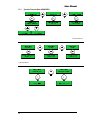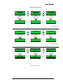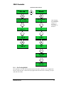
1
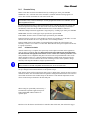
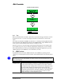
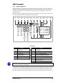
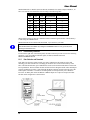
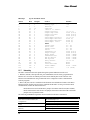
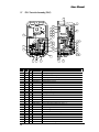
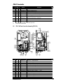
Assembly Technologies
PSI-C/C2 Controller
User Manual
Software Version PCX-2.0.0
Important Safeguards
For your protection, please read these instructions completely, and keep this manual for future reference.
Carefully observe and comply with all warnings, cautions and instructions placed on the equipment or
described in this manual.
© 2011, StanleyBlack&Decker, Inc., ALL RIGHTS RESERVED
www.StanleyAssembly.com
User Manual
Contents
Getting Started ...........................................................................................1
1.1
Warnings and Cautions ........................................................1
1.2
Qualified Personnel ..............................................................1
1.3
Safe Use ...............................................................................2
1.4
Introduction ...........................................................................2
1.5
Electrical Safety ....................................................................2
1.6
Specifications........................................................................3
1.6.1
Layout and Operator Interface.......................................4
Installation and Use....................................................................................5
2.1
Air Supply Requirement........................................................5
2.2
Mounting...............................................................................5
2.3
Tool Compatibility .................................................................6
2.3.1
Transducer Pulse and Impact Tools ..............................6
2.4
Main Menu and Application Programming ............................7
2.4.1
Check Harness ..............................................................7
2.4.2
Parameter Set-up ..........................................................8
2.4.2.1 Calibration/Correlation ...............................................8
2.4.2.1.1 Correlation Procedure.............................................9
2.4.2.2 Operation Flowchart Initial Set-up (PSI-C)...............10
2.4.3
Test..............................................................................11
2.5
ADMIN Functions................................................................11
2.5.1
Operation Flowchart Basic ADMIN MENU...................14
2.5.2
Error Proofing OK/NOK ...............................................17
2.5.2.1 Errors .......................................................................18
2.5.2.2 Normal Operation / Run Mode .................................18
2.5.3
Inputs / Outputs (I/O) ...................................................19
2.5.4
RJ45 Auxiliary Connector ............................................20
2.5.5
Data Collection and Download ....................................20
2.5.6
Serial Port....................................................................21
2.5.7
Networking...................................................................22
2.5.7.1 Standard Ethernet Protocol......................................23
2.5.7.1.1 Theory of Operation: .........................................23
2.5.7.1.2 Packets .............................................................23
2.5.8
Troubleshooting and Adjustments ...............................24
2.5.8.1 Transducer Calibration.............................................24
2.5.8.2 Set-up Problems ......................................................25
2.5.8.3 Other Concerns .......................................................25
2.5.8.3.1 Tool Air Hose Length ............................................25
2.5.8.3.2 Air Pressure and Volume ......................................25
2.5.8.3.3 Excessive Cycle Time...........................................25
2.6
Service and Maintenance ...................................................25
2.7
PSI-C Controller Assembly (PSI-C) ....................................26
2.8
PSI-C HI-Flow Controller Assembly (PSI-C/H) ...................27
ii
PSI-C Controller
Getting Started
1.1
Warnings and Cautions
The safety notices and warnings for protection against loss of life (the users or service personnel)
or for the protection against damage to property are highlighted in this document by the terms and
pictograms defined here. The terms used in this document and marked on the equipment itself
have the following significance:
Danger
Indicates that death or severe
personal injury will result if
proper precautions are not taken.
Indicates a general hazard. This
icon appears as a part of a
Danger, Warning, or Caution
notice.
Warning
Indicates that death or severe
personal injury may result if
proper precautions are not taken.
Indicates that eye protection
should be worn. This icon
appears as a part of a Danger,
Warning, or Caution notice.
Caution
Indicates that property damage
may result if proper precautions
are not taken.
Read and understand all the
safety recommendations and all
operating instructions before
operating tools and controllers.
Indicates an electrical hazard.
This icon appears as a part of a
Danger, Warning, or Caution
notice.
Indicates an item of special
interest.
WARNING
To Avoid Injury:
•
Read and understand all the safety recommendations and all operating instructions before
operating tools and controllers. Save these instructions for future reference.
•
Train all operators in the safe and proper use of power tools. Operators should report any
unsafe condition to their supervisor.
•
Follow all safety recommendations in the manual that apply to the tools being used and the
nature of the work being performed.
•
Verify that all warning labels illustrated in this manual are readable. Replacement labels are
available at no additional cost from STANLEY ASSEMBLY TECHNOLOGIES.
1.2
Qualified Personnel
WARNING
To Avoid Injury:
•
Only allow suitably qualified personnel to install, program, or maintain this equipment and or
system.
•
These persons must be knowledgeable of any potential sources of danger and maintenance
measures as set out in the Installation, Operations, and Maintenance manual.
•
This product must be transported, stored, and installed as intended, and maintained and
operated with care to ensure that the product functions correctly and safely.
•
Persons responsible for system planning and design must be familiar with the safety concepts
of automation equipment.
Getting Started
1
User Manual
1.3
Safe Use
This manual is intended to promote proper and safe use and give guidance to owners, employers,
supervisors, and others responsible for training and safe use by operators and maintainers. Stanley
controllers are intended for use in industrial threaded fastening or precision position and or
adjustment applications only. Some instructions may not apply to all applications. Please contact
your Stanley Sales Engineer for further information or assistance on Stanley training or assembly
tool operations.
1.4
Introduction
The PSI-C Controller provides closed-loop torque control and torque validation (available with
date and time stamp). It is easy to program, has common network-ready hardware available and
uses industry standard protocols.
The PSI-C Controller provides precise torque control as well as multiple parameter set capability
and Poke-Yoke error proofing to compatible transducer pulse tools. With the available DTU, up to
576 fastening cycles are stored, STATISTICS calculated with DATE/TIME and easily transfers to
Microsoft Windows Excel.
Compact in design, the PSI-C Controller provides operator feedback via a large digital display for
parameter set identification as well as torque and joint condition status and color LEDs for
fastener counting. There are OK / NOK indicator lights for finished cycle or batch evaluation for
in and out-of-spec conditions. Available with eight parameter sets allowing different counts and
application set-ups, one tool can be set to perform various applications using its full torque range.
The PSI-C2 offers all the same functionality as the PSI-C with the added benefits of running the
PSI series tools with memory or an absolute position sensor for controlling/monitoring angle
rotation of the fastener.
This manual uses the name PSI-C in the text. This name, PSI-C, is for both the PSI-C and C2
controller. Any differences will be specifically called out.
1.5
Electrical Safety
The issue of operator safety is of maximum importance from both the attitude of ergonomic
comfort as well as electrical safety.
The PSI-C controller operates from low voltage external AC or DC power. The standard
configuration utilizes a CE approved power supply that is UL listed. It consists of a wall mount
120VAC transformer with a 16VAC at 1 Amp power output.
See Table 1, below, for the appropriate power supply for your country.
Country
Voltage
Current
Part #
Japan
100 VAC
1 Amp
24X500143
Australia
240 VAC
1 Amp
24X500144
United Kingdom
240 VAC
1 Amp
24X500145
Europe
220 VAC
1 Amp
24X500146
U.S.A.
110 VAC
1 Amp
24X500092
Table 1
2
PSI-C Controller
WARNING
ELECTRICAL HAZARD
To Avoid Injury:
•
•
Plug power cord into a grounded outlet that conforms to National Electric Code standards.
Do not defeat the grounding pin on plug or substitute a cable that does not conform to the
power and safety requirements of system.
1.6
Specifications
Specification
Power
Pneumatic Source
Operating Conditions
Weight
Dimensions
Inputs
Outputs
Printer (optional)
Serial Port
Interface
Five-button keypad
LED Indicator
Ethernet (optional)
DTU - Data Transfer
Unit (optional)
Getting Started
Description
External Wall Mount Transformer to 16VAC, 50 Hz, 1 AMP
50 scfm @ 6 bar pressure (87psi)
Temperature: 0 to +50 degrees Celsius
Humidity: 0 – 95% non condensing
3.5 kg. (7.8lbs)
8.24” wide X 14.43” height X 6.38” depth
Six Discrete 12-24V Optically Isolated Inputs with screw lug terminals
Inputs available: Batch Reset, Manual Wrench Accept, Parameter
Select (3) and Disable
Four Dry Contact Relays with screw lug terminals
Outputs available: Cycle Accept / Reject, Batch Accept / Reject
CE, UL & VED rated up to 7 amps at 48V AC/DC
Internal Thermal Printer for documentation of cycle data onto
individual labels; 2” x 4” adhesive backed
RS 232 port; RJ45 connector
Dual Line 0.5” LCD backlit (16) character
Up, Down, Enter (Menu), Back and ADMIN
Back button: Momentary for Batch reset, hold down two seconds for
override.
CYCLE OK / NOK and BATCH OK / NOK Indicators
Separate IP address with buffered memory provides asynchronous
network communication.
Supports standard Windows based TCP/IP (10baseT) protocol; female
RJ-45 connector
Expands PSI-C functions to use eight (8) parameter sets,
Storage memory of fastening cycle data (72 readings/PSET)
Statistics and date/time information.
3
User Manual
1.6.1
4
Layout and Operator Interface
PSI-C Controller
Installation and Use
WARNING
To Avoid Injury:
•
Always wear eye and foot protection when installing equipment.
•
Keep the work area clean, well lit and uncluttered.
•
Keep unauthorized personnel out of the work area.
•
Do not install worn, damaged, or modified equipment that may be unsuitable for safe us.
•
Train all operators in the safe and proper use of power tools.
•
Operators should report any unsafe condition.
•
Install tools in dry, indoor, non-flammable, and non-explosive environments only.
2.1
Air Supply Requirement
A supply of compressed, dry, filtered air is required to run the pulse or impact tools connected to a
PSI-C controller. Please check the individual tool specification for air flow and pressure
requirements. Most tool specifications are based on 90 psi (6 Bar) for full range operation.
However, the PSI-C controller will operate at any level as long as the air pressure and volume are
sufficient for the tool to reach the required torque. The supply air hose should be a ½ inch (15mm)
or 3/8 inch (10 mm) inside diameter with no restrictions (fittings) smaller than 3/8 inch inside
diameter. If the air pressure and volume are insufficient, the performance of the tool suffers and
the full torque range of the tool will not be realized. If the PSI-C controller does not receive
sufficient air volume, the tool may operate erratically and the controller indicates a bad cycle or no
change on the display.
Install the PSI-C controller with an air filter before the air inlet to the controller. If a lubricator is
used, it can be installed before the controller or between the controller and the tool. The lubricator
must be a free flowing design and not smaller than ½ inch NPT.
NOTE:
Some lubricators act as a check valve and will not allow air flow back thru the lubricator.
This type is not recommended for use with the PSI-C.
The air hose/cable for the AH, AM, AT and AP series of tools is called the GEMINI. The
GEMINI air hose includes an integral transducer cable and is available in 3/8 inch I.D., coiled or
straight and available in many lengths. A separate transducer cable is also available. Prevent any
unnecessary restrictions, elbows, swivels, etc between the controller and the tool to prevent air
flow (volume) restrictions.
2.2
Mounting
Installation and Use
5
User Manual
Ø0.45 TYP
" "
14.43
13.38
OK
NOK
8.24
Mounting Dimensions
WW W. SIGM A-SIXN
. ET
I NTERNATI ONALPAT E
N TSPENDI NG
Typical Assembly Line Installation
WARNING
To Avoid Injury:.
•
- Shutoff valve must be in the closed position until the air lines are installed and properly terminated
•
- Do not connect power to the PSI-C Controller until all air line connections are secured.
•
- Supply air energizes the outlet port when electrical power is supplied to the PSI-C Controller.
2.3
2.3.1
Tool Compatibility
Transducer Pulse and Impact Tools
In addition to the PSI series of transducer pulse and impact tools, the PSI-C controller is available
to control all other major brands of Transducer Pulse tools including URYU and Yokota/IR.
6
PSI-C Controller
Make certain that the range of the tool being used is capable of the torque required. If prevailing
torque is present or the joint is very soft, then an over-sized tool may be required.
NOTE:
With ALL pulse tools, large (heavy) sockets, loose fitting or worn sockets, extensions and universal
sockets WILL reduce the efficiency of the tool and increase torque scatter.
All PSI tools should be equipped with EcoDrive sockets and extensions for the AH and AM tools or
the Taper Lock sockets and extensions for all AP and AT tools. Performance and capability
statements or claims are not ensured without these speciality sockets and attachments.
Oversize the tool as needed to prevent premature tool wear and long cycle times. Prevailing torque
and torque losses due to loose and/or worn sockets and extensions will reduce tool life, increase
cycle times and increase torque scatter.
AT60PB- 675
AM30PB-70
2.4
Main Menu and Application Programming
WARNING
To Avoid Injury:
•
For maximum tool life do not use the tool higher than 90% of the maximum torque output of
the tool.
1. The pulse unit adjustment screw in the tool must be set for the highest output of the tool or at
least the high limit of your application. Adjust the screw fully clockwise until it seats; then back it
out approximately 1-2 turns or until the operation of the tool is uniform and smooth when pulsing.
2. Check the maximum torque of the tool to insure that it can obtain the torque required.
3. Install and attach the GEMINI air hose/transducer cable to the bottom of the PSI-C and the tool.
Air hose and transducer cable versions depend upon the PSI-C and tool being used.
4. Upon power up, hold down both the ENTER and BACK keys simultaneously until the display
reads CLEAR COMPLETE. This returns all settings to the factory defaults. Observe the display to
determine both the type of software and code/revision date installed.
5. The PSI-C automatically zeros and checks the tool’s transducer, then shows PSET 1 NOT SET
UP.
6. Press the ENTER key (left key) after controller power up to display the MAIN MENU. Use the
UP/DOWN key to scroll through the MAIN MENU.
2.4.1
Check Harness
Installation and Use
7
User Manual
2.4.2
Parameter Set-up
PSET 1 NOT SET UP: Select the PSET desired by scrolling up or down, press ENTER.
NOMINAL CAL: A default value of the transducer’s nominal calibration setting appears on
screen. The tool has its nominal cal value stated on the tool.
NOTE:
The cal value is only correct if sensitivity is correctly programmed. Refer to the calibration run-off
sheet supplied with the tool.
If required engineering units are different than those shown, calculate the full scale in units, and
then scroll up or down to change the value on the screen. Press the ENTER key and the PSI-C
automatically checks and sets the ZERO and MAX values of the transducer connected.
TARGET TORQUE: Enter the application’s target torque by scrolling up or down, press ENTER.
HIGH LIMIT: Scroll to set the upper torque specification, press ENTER.
LOW LIMIT: Scroll to set the low limit torque specification, press ENTER.
BATCH COUNT: Scroll up to set the number of fasteners per assembly to use the PSI-C to count
fasteners. Set this number to zero to stop the PSI-C from counting fasteners.
BATCH TIME: Scroll to the number of seconds adequate to tighten all of the fasteners per
assembly. Set this to zero if there is no time limit. BATCH time starts upon completion of the first
in a group of fasteners.
2.4.2.1
Calibration/Correlation
After the initial set up is complete, the system may need to adjust correlation to the application
using an approved method. It is very important that the final calibration be performed using
the same method and equipment that will be used to evaluate the results in production. Some
rotary transducers are compatible with pulse tools and can be used just behind the socket as the
master transducer. However, it must be understood that the residual torque measured once the
rotary transducer is removed from the drive train will change because of the dynamics change
caused by removing the transducer (weight, speed and losses).
NOTE:
Rotary transducers are not compatible with the AM/A, AP, AH or AT series tools.
Include any extensions that will be used in the application as it will affect the final torque if the
set-up is changed. This method calibrates to the dynamic torque.
If the fastener torque will be judged using static torque, a digital torque wrench can also be used to
calibrate the PSI-C after the fastener has been tightened. Using this method ensures more effective
control and correlation of the residual torque on the fastener. This method compensates for the
effects of initial torque relaxation in the fastened joint.
When testing for repeatability and accuracy, a
TVM measures dynamic applied torque AT
THE FASTENER without influence of
operator input.
Run the tool on the fastener until the PSI-C controller shuts off the tool, then release the trigger.
8
PSI-C Controller
For both OK and NOK cycles, check the master transducer reading, or the residual torque reading
from the torque wrench, versus the reading on the PSI-C controller. These numbers generally vary.
Use CORRELATION under ADMIN to bring the two readings into correlation (see Correlation
Procedure below). A few more fasteners may be run to check the reading consistency between the
two.
If the program completes this cycle but LOW TQ or TQ NOT REACHED is received, check for:
• Target torque is above the capacity of the tool
• The pulse mechanism is not adjusted to the maximum.
• Insufficient supply air pressure. Check pressure when free-running tool; air pressure
should not drop more than 10 psi from the static air pressure available.
• Incorrect NOMINAL CAL VALUE was entered.
2.4.2.1.1
Correlation Procedure
1. From this RUN screen, without clearing the last reading, access the ADMIN functions via the
ADMIN key. Quickly press the ADMIN key to display options.
2. Use the UP or DOWN keys to scroll through and find the CORRELATION option. Press the
ENTER button.
3. MANUAL or AUTO CAL can be selected. Press the UP key or DOWN key accordingly.
AUTO CAL allows the entry of the master torque reading to be entered by scrolling up or down
until the master value is entered.
NOTE:
Adjust using AUTO CAL by setting the MASTER reading to about 60-70% of the actual measured
torque. Repeat as needed until the two readings correlate.
4. Press ENTER and note the new Correlation Value which is calculated automatically.
5. Press the BACK button to return to run screen.
6. Repeat this process until the readings from the master and the PSI-C match within 2% or as
required by your ISO procedures.
Installation and Use
9
User Manual
2.4.2.2
Operation Flowchart Initial Set-up (PSI-C)
Use the UP / DWN
arrows to find the
parameter set desired.
Press ENTER to select.
Continued on Next Page
10
PSI-C Controller
Operation Flowchart Continued
2.4.3
Test
Run a few normal fasteners. The PSI-C shuts off the tool. Release the trigger (the PSI-C resets the
internal shut-off valve. If you leave the trigger pressed the tool turns back on). Check torque
results.
The system is not defaulted for REHIT error detection, i.e. re-hitting an already tightened fastener.
Set up this feature using MIN PULSE COUNT in the ADMIN MENU. Adjust ADMIN functions
for the system to detect a REHIT fastener and error or display as a fault.
Run the tool in free air, release the trigger and the program should ignore the run, display LOW
TQ or ABORT. Slip off or strip out a fastener and the display should ignore, error or read SLIP.
If the results obtained are not correct, press ENTER and re-program the application or go to the
ADMIN functions via the ADMIN key. Use the BACK key to return.
2.5
ADMIN Functions
From the RUN screen, access the ADMIN functions via the ADMIN key. Quickly press the
ADMIN key, scroll through the functions using the UP and DOWN buttons; the following options
display:
NOTE:
After adjusting function(s), press ENTER to accept the change, then press the BACK UP key until
the run screen appears.
Function
Description
CORRELATION
Provides an easy transducer correlation to an independent measuring system
or torque wrench. When using a torque transducer system, make a rundown
and compare the torque reading from the controller to the independent system.
The torque reading from the last rundown appears in the top line of the
display as TQ:. By scrolling up or down, enter the value from the independent
measurement in the bottom line of the display as REF TQ. This changes the
transducer calibration value by the percent difference of the two. Future
readings should agree with the independent system.
Installation and Use
11
User Manual
Function
START PSI
(ADJUST)
PRE-TRIGGER
THRESHOLD
PULSE DELAY
DOWNSHIFT
MAX PULSE
COUNT
MIN PULSE
COUNT
CYCLE
COUNTER
BATCH
COUNT
BATCH TIMER
TARGET
TORQUE / HI
LIMIT / LOW
LIMIT
12
Description
Enables changes to be made to the tool’s starting PSI level (air pressure). This
is called START PSI because the PSI-C default setting operates from this start
value. In order to reach TARGET TQ as quickly as possible, adjust this to a
higher level and/or enable RAMP SPEED (see below).
This allows an early tool shut-off in order to control any torque over-shoot
that may occur in certain difficult applications. Press the ENTER button and
two values will appear. The A value in the amount of over-torque that
occurred from the last rundown. The PT value is the amount of pre-trigger
torque. Scroll UP to set the amount of pre-trigger desired, then press ENTER
to activate this feature.
This is the torque setting where the PSI-C deems that a fastening event has
begun. This is automatically set to 30% of the TARGET TQ or another predetermined value. Scroll to alter. Press ENTER to activate change.
The PSI-C can ignore the initial pulses from the tool. This is required to
eliminate any pulse spiking from the initial pulse (s). This can happen due to
the high free-speed of the tool. This is defaulted to one (1) pulse. Adjust to a
higher number to cover worst case applications such as hard joints and loose
sockets/extensions.
This allows the end of the fastening cycle to be slowed down in order to
control torque over-shoot. TORQUE appears when ENTER is pressed
showing the TARGET TQ. Scroll down to set the TORQUE to initiate
DOWNSHIFT. Press ENTER. PSI appears. Scroll to the PSI level which the
tool will run until TARGET TQ is achieved.
This sets a maximum allowable PULSE COUNT before the cycle is
REJECTED. If a strip or cross-thread occurs, this can help detect the bad
cycle. It can also detect a failing pulse pack unit. Press ENTER and LAST
RUN and MAX PULSE CT setting appears. The setting can be tested at this
point. Watch the screen and run some good and bad cycles. Adjust MAX
PULSE CT setting until satisfied. Press ENTER to activate.
This sets a minimum allowable PULSE COUNT before the cycle is
REJECTED. If a previous tightened fastener or a cross-thread occurs, this can
detect the bad cycle. Press ENTER and pulse counts from the LAST RUN,
then the MIN PULSE CT setting appears. Scroll UP or DOWN to set the MIN
PULSE CT. The setting can be tested at this point. Watch the screen and run
some good and bad cycles. Adjust MIN PULSE CT setting until satisfied.
Press ENTER to activate.
This allows a maintenance cycle counter to be set that counts down from a
selectable number of cycles. Once this number of cycles is achieved, a
MAINTENANCE REQUIRED screen appears so that normal pulse tool
maintenance can be performed. Press ENTER and UP/SET, DWN/CLEAR
appears. Press UP and CYCLES appear. Scroll UP to set the number of cycles
to count.
Press ENTER to adjust the BATCH COUNT or the total fasteners to be run
successfully on the part. Press ENTER and scroll UP or DOWN to alter the
fastener COUNT per BATCH.
Press ENTER to adjust the BATCH TIME or the total cycle time for all
fasteners to be run successfully on the part. Zero is equal to OFF or no timer.
Press ENTER and scroll UP or DOWN to alter the number of SECONDS
allowed for the BATCH. If all fasteners are not successfully tightened in the
allotted time, a Batch NOK occurs.
Adjust the torque target, high or low limit if the specification changes.
PSI-C Controller
Function
LOW LIMIT
GRN ON
CYCLE DELAY
TIME/DATE
DATA
I/O (Latched or
Momentary)
ADMIN LOCK
ON/OFF
SENSITIVITY
ETHERNET
PRETORQUE
RAMP
Installation and Use
Description
Use the ENTER button to toggle ON/OFF whether the green (OK) LED light
turns ON after the LOW LIMIT is crossed. If OFF is chosen, the green LED
turns on when TARGET TQ is achieved. Scroll to the next ADMIN function.
Press the BACK button to return to the RUN screen.
This setting determines the off time between the end of one run-down and tool
reset for the next cycle. The total range of adjustment is between 10 and 1000
counts. This relates to .25 second to four seconds of off time. The default
value of 100 keeps the tool off for about one half second before allowing the
operator to press the trigger for the next fastener. If this is too slow, adjust (by
using the UP/DWN buttons) the value down to approximately 60-80. Any
lower may be too quick and may not allow the operator enough time to release
the trigger. A higher value causes the tool to reset slower.
Sets TIME and DATE. Press UP to SET. Scroll to change. Press ENTER.
Press DOWN to exit.
Allows the download of all data stored on optional DTU (Data Transfer Unit).
Press ENTER and then DOWN to download all RS232 serial data through
RJ45 serial port. Press UP to CLEAR all DATA.
Allows the outputs to be latched until the next cycle starts or momentary,
which turns the outputs off two seconds after the completion of the cycle.
Toggle by pressing ENTER. Scroll UP or DOWN to move to the next option.
Initially turning this feature ON allows the entry of a four button code using
the existing four keys in a programmable order. Once this is done, this
programmed button order must be entered every time the ADMIN MENU is
accessed through the ADMIN button. Turning this OFF allows entry to the
ADMIN MENU without a four button code.
Sets the level of sensitivity for the transducer circuit to reduce the negative
effects of loose sockets, poor alignment and/or electrical noise from affecting
the torque readings. Default setting is seven (7) for most impact tools and 14
for pulse tools.
NOTE: A change to the SENSITIVITY setting requires an adjustment or
resetting of the CALIBRATION VALUE.
Allows entry of the UNIT IP ADDRESS. Scroll UP or DOWN to change.
Press ENTER. After changing the settings under ETHERNET, it is necessary
turn the power to the PSI-C off and on.
Allows the setup of a two-step fastening procedure. This is used for wheels,
cylinder heads or any assembly that requires a snug torque before a final
torque to compensate for relaxation. Press ENTER. Scroll UP to choose
PRETORQUE. This is usually 50-60% of the specified final torque. Press
ENTER.
NOTE: BATCH COUNT must be programmed for correct sequencing.
The Run Screen now shows PTQ when running PRETORQUE or snug
torque. PRETORQUE all fasteners. When the PRETORQUE BATCH is
finished OK. The Run Screen changes to show TQ. Final Torque all fasteners.
NOTE: MIN PULSE COUNT may need to be adjusted to accept final torque,
while still rejecting a REHIT fastener.
ON / OFF can be chosen to enable increased air pressure from the START
PSI upon reaching THRESHOLD. The START PSI default value is 40 PSI.
This is to control the rundown speed and prevent torque scatter. When the tool
runs a fastener, the PSI is RAMPED up to maximum PSI until the TARGET
TQ is achieved (the speed at which this PSI is fixed). Press the ENTER button
to choose option. Scroll to the next ADMIN function. Press the BACK button
to return to the RUN screen.
13
User Manual
2.5.1
Operation Flowchart Basic ADMIN MENU
Continued Below
Continued Below
14
PSI-C Controller
Operation Flowchart Continued
Continued Below
Continued on Next Page
Installation and Use
15
User Manual
Operation Flowchart Continued
Continued Below
Continued Below
Continued On Next Page
16
PSI-C Controller
Operation Flowchart Continued
After changing
the ETHERNET
settings, it is
necessary to
cycle power on
the PSI-C.
2.5.2
Error Proofing OK/NOK
Error proofing is one of the most important features of the PSI-C controller. Once an application
has been setup, the PSI-C controls the torque applied and discerns between a fastening cycle pass
(OK) and error (NOK):
Installation and Use
17
User Manual
2.5.2.1
Errors
Error
LOW TORQUE
or Short Cycle
HIGH TORQUE
RE-HIT
MIN PULSE
COUNT
MAX PULSE
COUNT
Slip-off (or cam
out)
Short cycle
(premature cycle
abort)
Description
If the tool has run many cycles and the pulse oil or the air motor needs
maintenance, the tool may not be able to reach torque. The operator may be
stopping the cycle prior to completion of the fastening to TARGET TQ. This
sometimes occurs when the operator anticipates the end of cycle and releases
the trigger prematurely (before the PSI-C controller has shut-off the tool). If
LOW LIMIT GRN ON is chosen in the ADMIN MENU and the operator
releases the trigger after the LOW LIMIT has been passed, then a PASS
results, even though TARGET TORQUE has not been achieved.
This can occur if joint conditions change to a harder type joint than the
original, or the PSI has been adjusted to increase the tool speed beyond what
can be controlled consistently on the application. This can also occur if the
CAL VALUE is incorrect.
This occurs whenever the tool is applied to a pre-tightened fastener. This is
not a defaulted error condition. It must be set up through the MIN PULSE
COUNT in the ADMIN MENU. Once set up correctly, an NOK displays
when the tool is cycled on a previously tightened fastener. If a REHIT is
accepted, the MIN PULSE COUNT feature should be adjusted.
If a MIN number of PULSES is not achieved before TARGET TORQUE is
reached, an error occurs. Once set up correctly, if a previous tightened
fastener or a cross-thread occurs, a NOK results. The system default is zero
(0) pulse counts, which means all rundowns which result in a final torque
between LOW LIMIT and HIGH LIMIT will be OK.
If a strip or cross-thread occurs, this can cause too many pulses and a bad
cycle. This error can also occur if the pulse pack in the tool is in need of
service or failing.
If the socket or screwdriver bit slips off the fastener, the controller will not
count the cycle or alarm this condition as TQ LOW if the THRESHOLD has
not been crossed.
This feature insures that only attempts to tighten fasteners are counted. The
controller will not count the cycle or alarm this condition as TQ LOW if the
THRESHOLD has not been crossed.
NOTE:
The PSI-C ignores no-load running of the tool unless THRESHOLD is crossed.
2.5.2.2
Normal Operation / Run Mode
When operating in the RUN mode, the UP/ DOWN keys allow the operator to change between
parameter sets, unless the PSET LOCK OUT is activated. PSET LOCK OUT is recommended
when only one PSET is being utilized.
Pressing the BACK button clears the batch. The BATCH NOK output fires and turns on the red
BATCH LED.
Pressing and holding the BACK button for one to two seconds puts the PSI-C in OVER-RIDE
mode. OVER-RIDE means that the system has full power without any torque control or shut-off
capabilities.
The PSI-C has a two line main display. This shows the final TORQUE, Parameter or PSET, the
BATCH or fastener COUNT and the BATCH TIMER. BATCH COUNT represents the number of
fasteners that the PSI-C has been programmed to count (per BATCH). LED lights change to
GREEN upon reaching an OK or GOOD fastening cycle. Outputs and CYCLE lights on the tool,
if applicable, fire automatically. CYCLE lights on the tool can be fired after crossing the LOW
LIMIT or when TARGET TORQUE is achieved.
The BATCH light on the PSI-C and internal outputs also fire automatically. Running the next
cycle clears these lights and resets outputs automatically. Select I/O MOMENTARY from the
ADMIN MENU to clear the cycle lights and reset the outputs after two seconds.
18
PSI-C Controller
2.5.3
Inputs / Outputs (I/O)
Output signal lines are switched by closing normally open relay contacts. These relays conform to
VDE0435, UL508 and CSA22.2. Signal power is customer supplied and may be AC or DC up to
48 volts. The maximum current capacity of the relay circuitry is seven amps per contact with
seven amps total.
Inputs are optically decoupled from other circuitry. These signals must be between 12 and 24 volts
DC. The design will accept DC input signals of either polarity.
3
4
5
BATCH
BATCH
CYCLE
CYCLE
6
7
BATCH
2
DISABLE
1
8
9 10 11 12
0 0 1=PS1
0 1 0=PS2
0 1 1=PS3
1 0 0=PS4
I/O Schematic
Outputs
Inputs
Pin #
Description
Pin #
Description
1
OUTPUT COMMON BUS
6
DISABLE TOOL
2
CYCLE OK
7
BATCH / REJECT RESET
3
4
CYCLE NOK
BATCH OK
8
9
MANUAL WRENCH ACCEPT
PSET Select BIT 3
5
BATCH NOK
10
PSET Select BIT 2
11
PSET Select BIT1
12
INPUT COMMON BUS
NOTE:
I/O Connector Plug Part No. 24X500537.
The PSI-C I/O terminal strip is located externally on the bottom of the PSI-C. Certain remote
connections are also accessible via the RJ45 socket located on the right side bottom panel and can
be easily accessed using the ROI (Remote Operator Interface). Standard I/O is optically isolated
and relay operated using dry contacts; normally open. I/O must be powered from a remote source.
Installation and Use
19
User Manual
Standard INPUTS are: Disable (Part Not-Present) and Batch Clear (Reset). Input terminals 9, 10
and 11 are used to select Parameter Sets according to the following table:
Pin 9
Pin 10
Pin 11
Parameter Set
Binary + 1
Off
Off
Off
Keypad Selects
1
Off
Off
On
1
2
Off
On
Off
2
3
Off
On
On
3
4
On
Off
Off
4
5
On
Off
On
5
6
On
On
Off
6
7
On
On
On
7
8
When all three inputs are OFF the controller returns to manual keypad selection. Choose Binary +
1 mode using the ADMIN button.
Standard OUTPUTS are: Batch NOK, Batch OK, Cycle OK and Cycle NOK.
NOTE:
Remote Batch Reset is available by holding the OVERRIDE button for one (1) second, then
pressing the UP button once.
2.5.4
RJ45 Auxiliary Connector
Located on the right side of the bottom panel, the RJ45 connector provides access to the following
functions: Cycle Accept/Reject indicator lights, UP button, DOWN button and
RESET/OVERRIDE button.
2.5.5
Data Collection and Download
If the PSI-C has the DTU (Data Transfer Unit, Part # 24K500172) all parameter values and
fastening cycle data from the last 72 readings per Parameter Set is stored in the memory of the
DTU. The Data Transfer Kit (part # 24K500340) can be used to download this data to a Microsoft
Excel spreadsheet. The kit includes the Data Transfer Software Program and all cables and adapter
required. An RS232 serial bus is ported through the RJ45 connector located on the left side of the
bottom panel of the PSI-C. The data is sent through this serial output directly into a Windows
Excel file. An RJ45 patch cable and RJ45/F to DB9/S adapter are required to output serial data.
The data cable configuration is shown below.
20
PSI-C Controller
Data Collection Transfer Kit — Part # 24K500340
Once the Data Collection Cable Assembly is correctly assembled, open the Data Collection
software program. Select the COM Port. Go into the ADMIN MENU of the PSI-C and scroll to
DATA. Press ENTER. Press DOWN to download all data from the current Parameter Set. Name
and save the Microsoft Excel Spreadsheet.
Press UP to clear all DATA.
The data format is as follows:
NOMINAL CAL VALUE (NM)
125.1
TARGET TQ
HI LIMIT
LO LIMIT
THRESHOLD
21
24
18
10.5
MIN PULSES
MAX PULSES
0
500
DOWNSHIFT TQ
DOWNSHIFT PSI
21
44
START PSI
NUMBER OF BOLTS
SENSITIVITY
44
1
7
MIN
21
MAX
21.6
AVG
21.1633
RANGE
0.6
STD. DEV.
0.182857271
6 SIGMA
1.097143627
% 6 SIGMA
0.051841721
CPK
5.171003317
NUMBER OF READINGS STORED
30
CPR
0.008640287
READING TIME/DATE RESULT
03-28-08 4:19:22 21.0
03-28-08 4:19:24 21.1
03-28-08 4:19:26 21.0
03-28-08 4:19:28 21.1
Internal Wiring for RJ45 to DB9F Adapters
Data Collection – RJ45 Serial Adapter to DB9F
(Part # 24K500496)
Network (Serial) Protocol, PFCS Check &
Cooper Cart – RJ45 Adaptor to DB9F
(Part # 24K500497)
2.5.6
RJ45 Pin
5
7
3
5
6
3
DB9 Pin
5
2
3
5
2
3
Serial Port
If no network card is installed in the PSI-C then the serial port will provide an output string after
each rundown that passes the Threshold Torque value. Here is a sample of the output string.
Installation and Use
21
User Manual
Message
Cycle Rundown Data
Start
End
Length
Field
Format
1
2
4
5
17
23
24
29
34
39
40
45
50
55
56
58
60
62
64
69
74
79
84
89
94
95
135
151
1
3
4
16
22
23
28
33
38
40
44
49
54
55
57
59
61
63
68
73
78
83
88
93
94
134
150
155
1
2
1
12
6
1
5
5
5
1
5
5
5
1
2
2
2
2
5
5
5
5
5
5
1
40
16
5
Begin measuring data
Message Type
Revision
Time/Date
‘FF0101’ or ‘PP0101’
Torque Pass/Fail
Torque High Limit
Torque Low Limit
Torque Final
Pulse/Angle Pass/Fail
Pulse/Angle Max Limit
Pulse/Angle Min Limit
Pulse/Angle Final
UNITS
Current Pset
Batch Count
Current Count
Filter
Transducer Cal
Target Torque
Angle Target
Transducer Zero
Adc Tq Shutoff
Adc Tq Final
Early Release
Barcode
Controller Name
Packet Number
'*'
'13'
‘A'
'P' or 'F'
01000 (100.0)
01000 (100.0)
01000 (100.0)
'P' or 'F'
00005 (5)
00005 (5)
00005 (5)
1 – 5
01 - 08
01 - 99
01 - 99
01 - 64
01000 (100.0)
01000 (100.0)
00000 - 99999
00000 - 04095
00000 - 04095
00000 – 04095
‘Y’ or ‘N’
ASCII
ASCII
00000 – 65535
156
156
1
End of Data
‘\r’ (0x0D)
2.5.7
Networking
The PSI-C is Ethernet Network capable through an optional Ethernet Network card.
1. Ethernet (TCP/IP): This optional card, part #24B500502, must be factory programmed for
Ethernet. It is accessed via an RJ45 port located on the bottom panel of the enclosure. The
Ethernet card communicates using TCP/IP and can be configured to utilize communication
software programs.
2. PFCS (Chrysler): PFCS is available in both Serial RS 232 and Ethernet formats. If the PFCS
Ethernet network card has not been factory installed and the PSI-C is being converted to PFCS
communication, follow the instructions below.
PFCS Ethernet network card: Remove jumpers from main control board (JP1 and JP2).
PFCS Serial network card: Remove all jumpers from main control board JP1 and install
jumpers onto all positions on JP2.
The following JUMPER arrangements must be installed on the PSI-C main board:
DATA or NETWORK Configurations
JP1 -Install Jumpers 1,2
JP 2 -Install Jumpers 2,3,5
JP 1 -No Jumpers Installed
J JP 2 -Install All Jumpers
JP 1 -No Jumpers Installed
JP 2 -No Jumpers Installed
Data Collection and Download (Std.
Configuration)
Network Card – Serial Protocols (PFCS & Std.
Serial)
Network Card – Ethernet Protocols (PFCS
Ethernet)
22
PSI-C Controller
DATA or NETWORK Configurations
Printer Installation (Part #24X500173)
Install Cable (Part # 24C500400) From Network Card Board
To J6
JP 1 -Install Jumpers 1,2
JP 2 -Install Jumpers 2,3,5
Cable (Part # 24X500544) From Printer To J8
J8 - PRINTER JACK
DATA/POWER
JP1 - JUMPER PINS
JP2 - JUMPER PINS
J6 - RJ45 NETWORK JACK
2.5.7.1
2.5.7.1.1
Standard Ethernet Protocol
Theory of Operation:
The PSI-C standard Ethernet protocol supports three messages on port 4240.
Every time the controller has a result (OK, NOK), the network card sends a cycle
data packet to the server. The network card attempts to send this packet three
times. If an acknowledgement packet is not received, the controller disconnects
from the server and attempts a new connection. If the network card has not
transmitted a final data packet within two minutes of the last one, it sends a Keep
Alive message to the server to keep the connection open.
2.5.7.1.2 Packets
Message
Cycle Rundown Data Psi-C, -C2
Start
End
Length
Field
Format
1
2
4
5
17
23
24
29
34
39
40
45
50
55
56
58
1
3
4
16
22
23
28
33
38
40
44
49
54
55
57
59
1
2
1
12
6
1
5
5
5
1
5
5
5
1
2
2
Begin measuring data
Message Type
Revision
Time/Date
‘FF0101’ or ‘PP0101’
Torque Pass/Fail
Torque High Limit
Torque Low Limit
Torque Final
Pulse/Angle Pass/Fail
Pulse/Angle Max Limit
Pulse/Angle Min Limit
Pulse/Angle Final
Strategy
Current Pset
Batch Count
'*'
'13'
‘A'
Installation and Use
'P' or 'F'
01000 (100.0)
01000 (100.0)
01000 (100.0)
'P' or 'F'
00005 (5)
00005 (5)
00005 (5)
'0' - '9'
01 - 08
01 - 99
23
User Manual
60
62
64
69
74
79
84
89
94
95
135
151
156
61
63
68
73
78
83
88
93
94
134
150
155
156
2
2
5
5
5
5
5
5
1
40
16
5
1
Current Count
Sensitivity
Transducer Cal
Target Torque
Angle Target
Transducer Zero
Adc Tq Shutoff
Adc Tq Final
Early Release
Barcode
Controller Name
Packet Number
End of Data
01 - 99
01 - 64
01000 (100.0)
01000 (100.0)
00000 - 99999
00000 - 04095
00000 - 04095
00000 – 04095
‘Y’ or ‘N’
ASCII
ASCII
00000 – 65535
‘\r’ (0x0D)
Direction: Controller to Host
Retries: 3
Notes: After three retries the unit will close the connection.
Message
Keep Alive
Start
1
2
4
5
21
End
1
3
4
20
21
Length
1
2
1
16
1
Field
Begin measuring data
Message Type
Revision
Controller Name
End of Data
Format
'*'
'98'
‘A'
ASCII
‘\r’ (0x0D)
Direction: Controller to Host
Retries: 3
Notes: Sent every 30 Seconds. After three retries the unit will
close the connection.
Message
Acknowledgement
Start
1
2
5
End
1
4
5
Length
1
3
1
Field
Begin measuring data
Message Type
End of Data
Format
'*'
'98R'
‘\r’ (0x0D)
Direction: Host to Controller
Notes: Sent in reply to Final Data or Keep Alive messages
2.5.8
2.5.8.1
Troubleshooting and Adjustments
Transducer Calibration
If the controller does not correlate once the NOMINAL CAL VALUE of the tool is programmed,
check the cable and connections.
-Substitute a known good cable and then a known good tool to determine if the tool’s
wiring/transducer or cable is defective.
Should the transducer set-up correctly but the torque value not agree with your MASTER:
-Check that the NOM CAL of the tool is correctly entered;
-Perform a CORRELATION routine described previously.
24
PSI-C Controller
NOTE:
Any added square drive extension, including a rotary transducer, causes efficiency loss and thus
torque loss at the fastener. Use only eCoDrive sockets and extensions for maximum efficiency.
2.5.8.2
Set-up Problems
The inability for the controller or tool to set up correctly may be due to too a bad cable connection
or wiring within the tool to the connector. This may be indicated by the controller screen reading
XDUCER FAIL or CALIBRATION FAILED. Check cable connections at the PSI-C and at the
tool. Change the cable if this does not correct the fault.
2.5.8.3
Other Concerns
2.5.8.3.1
Tool Air Hose Length
The PSI-C is designed to operate a tool with an 8’ - 25’ long, 3/8” inside diameter air hose.
However, the controller adjusts to any reasonable hose length, provided that the pressure drop and
restrictions do not affect the airflow volume. With a longer hose, the system may require a longer
dwell time between fasteners. See CYCLE DELAY under ADMIN functions. If the tool is
changed, the torque should be checked and the system calibrated with the new tool to ensure
proper function.
2.5.8.3.2
Air Pressure and Volume
Clean air at 90 psi with sufficient air volume is required in cases where the tool is being used at or
above 90% of its rated capacity. The air pressure required for a particular application varies
depending on the tool and the torque required. If the tool is used at >90% of its specified output,
then the available air pressure is critical in order to achieve torque. If the PSI-C setup requires 75
PSI to achieve torque with a particular tool, then the input air pressure to the controller must not
fall below 75 PSI when the tool is pulsing (or coming to final torque). If the facilities air pressure
falls more than 10 PSI from static reading when a tool is free-running, then the plant air volume
may not be sufficient for the application and a tool with more torque capacity may be required.
2.5.8.3.3
Excessive Cycle Time
If torque scatter is excessive, or the cycle time is too long, suspect the socket and/or extension.
Worn or broken sockets can cause erratic torque, long cycle times and excessive pulsing.
Extensions can rob the torque from a tool and stop it from reaching the fastener. If increasing the
air pressure and torque target does not shorten the cycle time or correct the scatter issue, then
remove the extension, shorten the extension or switch to the eCoDrive Fat Boy extension.
For any problem other than a bad socket/extension, substitute a known good cable first, then a
known good tool, then a known good PSI-C controller (in that order). One of these or a
combination will correct the issue. Send the problematic part in for repair. Please contact your
Stanley Sales Engineer for assistance.
If a CYCLE error displays often after a rundown, check the following settings in the ADMIN
MENU:
MIN PULSE COUNT, MAX PULSE COUNT, PULSE DELAY, LOW/HIGH LIMITS,
THRESHOLD and TARGET TORQUE. Refer to ADMIN functions section in this manual for
proper setup and definitions of these features.
The display will continue to indicate the error condition of the last failed cycle on the second line
of the display.
2.6
Service and Maintenance
The PSI-C requires no scheduled adjustments or maintenance. Ensure that the air supply is clean
and filtered and that any lubricator (if used) is installed after the box. If a lubricator is installed
before the controller, adjust it to the minimum setting. Any moisture present in the input air can
foul the main valve and render the controller inoperable.
Should service be required, contact your local distributor or Stanley Assembly Technologies.
Installation and Use
25
User Manual
2.7
PSI-C Controller Assembly (PSI-C)
33
1
32
31 30
2
25 24
27 26
39
29 28
12
3
36 37
13
38
17
4
15
7
18
23
9
5
22
20 21
19
10
*
*
*
*
*
26
Item
Qty
1
2
3
4
5
6
7
9
10
11
12
13
15
16
17
18
19
20
21
22
23
24
25
26
27
28
1
1
1
1
4
1
1
1
1
1
1
1
1
1
1
1
6
1
1
4
1
1
1
1
4
4
16
11
Part No.
24E500178
24X500195
24B500165
24B500229
24R500299
24X500193
24W510085
24X500008
24X500064
24X500192
24X500328
24X500018
24R500257
24C501500
24X500029
24X500194
24R500298
24X500211
24R500028
24R500224
24K500172
24X500196
24B500225
24X500331
24R500332
24R500299
6
34
Description
Enclosure – Molded Plastic
Overlay – Keypad
Main Board Assembly
Pre-Amp Board Assembly
Screw-Pan Head-High-Low #8 x ½”
Bottom Panel Cover
Valve – 2000
½” OD Tube
Bulkhead-Output 3/8 NPT – ½ Tube
Bulkhead-Input ½ F NPT – 3/8 M NPT
90 Degree Fitting – 3/8 NPT - ½ Tube
90 Degree Fitting – ¼ NPT – BARB
3/8” OD Tube
Harness-Transducer
Harness-Valve
Rear Panel Cover
Screw-Pan Head- High-Low #10 x ½”
Access Panel – Front-DTU
Label – Logo Bubble
Rivet – Finger
DTU – Data Transfer Unit (optional)
Printer Housing
Printer Board
Printer Head
Screw-Pan Head #2 x 3/8”
Screw-Pan Head-High-Low #8 x ½”
PSI-C Controller
Item
*
*
*
*
Qty
Part No.
Description
29
30
31
32
33
34
36
*
**
1
24X500544 Harness-Cable-Printer Data/Power
4
24X500197 Spindle-Paper Roll-Printer
4
24X500198 Washer-Spindle-Printer
4
24R500298 Screw-Pan Head-High-Low #10 x ½”
1
24X500147 Labels-Printer (Case of 20) (optional)
1
24X500092 Power Supply – Standard
1
24B500032 Network Card (Option - Serial)
1
24B500502 Network Card (Option - Ethernet)
37
1
24C500400 RJ45 Cable – Network
38
2
24R500102 Pan Head Screw 4-40 x 3/8”
39
1
24R500325 Cap Plug
Part of Printer Assembly -- #10780 (optional)
Used with Network Card
2.8
PSI-C HI-Flow Controller Assembly (PSI-C/H)
**
**
33
1
32
31 30
2
25 24
27 26
39
29 28
12
3
36 37
13
38
17
4
15
7
18
23
9
5
22
20 21
19
10
Item
Qty
1
2
3
4
5
6
7
9
10
11
12
13
14
15
1
1
1
1
4
1
1
1
1
1
1
1
1
1
16
11
Part No.
24E500178
24X500195
24B500165
24B500229
24R500299
24X500193
24X500025
24X500008
24X500064
24X500192
24R500268
24X500018
24R500289
24R500257
Installation and Use
6
34
Description
Enclosure – Molded Plastic
Overlay – Keypad
Main Board Assembly
Pre-Amp Board Assembly
Screw-Pan Head-High-Low #8 x ½”
Bottom Panel Cover
Valve – ITV 3000
½” OD Tube
Bulkhead-Output 3/8 NPT – ½ Tube
Bulkhead-Input ½ F NPT – 3/8 M NPT
90 Degree Fitting – ½ NPT - ½ Tube
90 Degree Fitting – ¼ NPT – BARB
Reducer Bushing – 3/8” – ¼”
3/8” OD Tube
27
User Manual
Item
*
*
*
*
*
*
*
*
*
**
**
*
**
28
16
17
18
19
20
21
22
23
24
25
26
27
28
29
30
31
32
33
34
36
Qty
Part No.
Description
1
24C501500 Harness-Transducer
1
24X500029 Harness- ITV Valve
1
24X500194 Rear Panel Cover
6
24R500298 Screw-Pan Head- High-Low #10 x ½”
1
24X500211 Access Panel – Front-DTU
1
24R500028 Label – Logo Bubble
4
24R500224 Rivet – Finger
1
24K500172 DTU – Data Transfer Unit (optional)
1
24X500196 Printer Housing
1
24B500225 Printer Board
1
24X500331 Printer Head
4
24R500332 Screw-Pan Head #2 x 3/8”
4
24R500299 Screw-Pan Head-High-Low #8 x ½”
1
24X500544 Harness-Cable-Printer Data/Power
4
24X500197 Spindle-Paper Roll-Printer
4
24X500198 Washer-Spindle-Printer
4
24R500298 Screw-Pan Head-High-Low #10 x ½”
1
24X500147 Labels-Printer (Case of 20) (optional)
1
24X500092 Power Supply – Standard
1
24B500032 Network Card (Option - Serial)
1
24B500502 Network Card (Option - Ethernet)
37
1
24C500400 RJ45 Cable – Network
38
2
24R500102 Pan Head Screw 4-40 x 3/8”
39
1
24R500325 Cap Plug
Part of Printer Assembly -- 24X500173 (optional)
Used with Network Card
PSI-C Controller
Contacts
STANLEY ASSEMBLY TECHNOLOGIES: 5335 Avion Park Drive, Cleveland, Ohio 441432328, USA Tel: +1 (440) 461-5500 Fax: +1 (440) 461-5592; [email protected]
STANLEY ASSEMBLY TECHNOLOGIES: Outils Portatifs et Systemes d’Assemblage, Zone
Immoparc – Route De Chartres, Bâtiment Loire 4, 78190 Trappes Cedex, France Tel: +33 (130)
50 91 00 Fax: +33 (130) 51 07 08; [email protected]
STANLEY DEUTSCHLAND GmbH: Division Assembly Technologies, Frankfurter Straße 74,
D-64521 Groß-Gerau, Germany Tel: +49 6152 8052 0 Fax: +49 6152 8052 22;
[email protected]
STANLEY ASSEMBLY TECHNOLOGIES: Divisione: SWK UTENSILERIE s.r.l., Via Parco
47, 20046 Biassono (MI), Italy Tel: +39 (039) 238-9950 Fax: +39 (039) 238-9970;
[email protected]
www.StanleyAssembly.com
Installation and Use
29