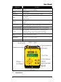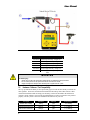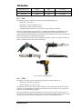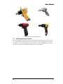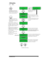
1
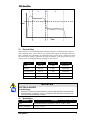
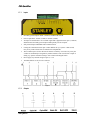
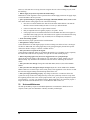
Assembly Technologies
PSI Qualifier User Manual
Installation and Programming
Important Safeguards
For your protection, please read these instructions completely, and keep this manual for future
reference. Carefully observe and comply with all warnings, cautions and instructions placed on the
equipment or described in this manual.
www.StanleyAssembly.com
© 2009, December THE STANLEY WORKS, ALL RIGHTS RESERVED
User Manual
Contents
Getting Started ...........................................................................................1
1.1
Warnings and Cautions ........................................................1
1.2
Qualified Personnel ..............................................................1
1.3
Safe Use ...............................................................................2
1.4
Introduction ...........................................................................2
1.5
Electrical Safety ....................................................................3
1.6
Specifications........................................................................3
1.7
Inputs/Outputs ......................................................................4
1.7.1
Inputs.............................................................................5
1.7.2
Outputs ..........................................................................5
1.8
RJ-45 Communications Port .................................................6
1.8.1
Networking.....................................................................6
Installation and Use....................................................................................7
2.1
Air Supply .............................................................................7
2.2
Hardware / Software / Tool Compatibility..............................8
2.2.1
PSI-Q.............................................................................9
2.2.2
PSI-Qc ...........................................................................9
2.3
Initial Setup Operation Flowchart........................................10
2.3.1
PSI-Q...........................................................................11
2.3.2
PSI-Qc .........................................................................13
2.4
Initial Set Up Menu .............................................................14
2.4.1
PSI-Q...........................................................................14
2.4.2
PSI-Qc .........................................................................15
2.4.3
Change Orifice.............................................................16
2.5
Administration Menu ...........................................................16
2.6
Operation Flowchart Admin Menu ......................................19
2.7
Drawing / BOM ...................................................................22
2.7.1
Qualifier Assembly.......................................................22
2.7.2
Qualifier Hi-Flow Assembly..........................................23
2.8
Troubleshooting and Adjustments ......................................23
2.9
Service and Maintenance ...................................................24
ii
PSI Qualifier
Getting Started
1.1
Warnings and Cautions
The safety notices and warnings for protection against loss of life (the users or service personnel)
or for the protection against damage to property are highlighted in this document by the terms and
pictograms defined here. The terms used in this document and marked on the equipment itself
have the following significance:
Danger
Indicates that death or severe
personal injury will result if
proper precautions are not taken.
Indicates a general hazard. This
icon appears as a part of a
Danger, Warning, or Caution
notice.
Warning
Indicates that death or severe
personal injury may result if
proper precautions are not taken.
Indicates that eye protection
should be worn. This icon
appears as a part of a Danger,
Warning, or Caution notice.
Caution
Indicates that property damage
may result if proper precautions
are not taken.
Read and understand all the
safety recommendations and all
operating instructions before
operating tools and controllers.
Indicates an electrical hazard.
This icon appears as a part of a
Danger, Warning, or Caution
notice.
Indicates an item of special
interest.
WARNING
To Avoid Injury:
•
Read and understand all the safety recommendations and all operating instructions before
operating tools and controllers. Save these instructions for future reference.
•
Train all operators in the safe and proper use of power tools. Operators should report any
unsafe condition to their supervisor.
•
Follow all safety recommendations in the manual that apply to the tools being used and the
nature of the work being performed.
•
Verify that all warning labels illustrated in this manual are readable. Replacement labels are
available at no additional cost from STANLEY ASSEMBLY TECHNOLOGIES.
1.2
Qualified Personnel
WARNING
To Avoid Injury:
•
Only allow suitably qualified personnel to install, program, or maintain this equipment and or
system.
•
These persons must be knowledgeable of any potential sources of danger and maintenance
measures as set out in the Installation, Operations, and Maintenance manual.
•
This product must be transported, stored, and installed as intended, and maintained and
operated with care to ensure that the product functions correctly and safely.
•
Persons responsible for system planning and design must be familiar with the safety concepts
of automation equipment.
Getting Started
1
User Manual
1.3
Safe Use
This manual is intended to promote proper and safe use and give guidance to owners, employers,
supervisors, and others responsible for training and safe use by operators and maintainers.
Qualifiers from Stanley Assembly Technologies are intended for use in industrial threaded
fastening or precision position and or adjustment applications only. Some instructions may not
apply to all applications. Please contact your Stanley Sales Engineer for further information or
assistance on Stanley training or Qualifier operations.
1.4
Introduction
The PSI-Q performs Poka-Yoke error proofing for shut-off air tools. Torque accuracy with shutoff type tools is usually good within ±15-20% depending on the consistency of the joint(s). This is
controlled by the tool’s internal shut-off mechanism.
The PSI-Qc performs Poka-Yoke error proofing for non-shutoff, or stall type, air tools or impact
wrenches. Torque accuracy with non shut-off pulse tools is usually good within ±5-15%
depending on the consistency of the joint(s) and the dependability of the operator. Better torque
accuracy can be achieved if the tool is allowed to run until the socket or fastener has nearly
stopped turning. The PSI-Qc can operate either with a signal light for the operator to release the
throttle or by actuating a solenoid valve which shuts off the air supply to the tool at cycle
complete.
All tools should be tested for torque accuracy periodically during the applications lifetime to
determine whether maintenance is required and also to determine a maintenance schedule.
The PSI-Q and PSI-Qc share many of the same components. The difference between the two is
the software and the PSI-Qc has the solenoid valve kit, part # 24A500190. Both of these systems
will be referred to as the “Q” systems in this manual when the descriptions are equivalent. They
are a process monitoring system and do not provide torque control or values. The “Q” systems
take a series of mass air flow measurements and turn the data into a fastening cycle signature to
detect OK vs. NOK fastening cycles.
Diagram 1 below shows a typical fastening cycle for a pulse, impact or geared tool. The air
consumption of a tool air motor during a fastening cycle is relative to the work being performed
and tool speed.
Zone 1 – Tool starts. The level of flow indicates if the fastener is cross-threaded or free spinning.
Zone 2 – Shows free speed and shows the free run-down of the bolt.
Zone 3 – Begins when the fastener has seated and reached Snug Torque.
Zone 4 – Final shut-off phase. Equilibrium has been achieved and the tool can be shut off and is
vented (throttle reset). When “Q” system senses this, it begins the pulse time counting. When the
programmed time is achieved, the cycle completes and the fastener is documented as OK.
If any Zone is not sensed by the “Q” system, then the fastening cycle is NOT OK.
2
PSI Qualifier
1
2
3
4
Flow
Time
Diagram 1: “Q” System Flow Signature
1.5
Electrical Safety
Operator safety is of maximum importance from the perspective of both ergonomic comfort as
well as electrical safety. This is why the “Q” Systems power supplies are CE approved and UL
listed. It consists of a wall mount VAC transformer with a 16VAC, 50 Hz, 1 Amp power output.
The specific power supply is ordered for the region in which the “Q” System is to be used. See
Table 1, below, for the appropriate power supply for your country.
Country
Voltage
Current
Part # to Order
Japan
100 VAC
1 Amp
24X500143
Australia
240 VAC
1 Amp
24X500144
United Kingdom
240 VAC
1 Amp
24X500145
Europe
220 VAC
1 Amp
24X500146
U.S.A.
110 VAC
1 Amp
24X500092
Table 1: International Power Supplies
WARNING
ELECTRICAL HAZARD
To Avoid Injury:
•
•
Plug power cord into a grounded outlet that conforms to National Electric Code standards.
Do not defeat the grounding pin on plug or substitute a cable that does not conform to the
power and safety requirements of system.
1.6
Specifications
Specification
Description
Power
External Wall Mount Transformer to 16VAC, 50 Hz, 1 AMP
Power Consumption
< 1 amp @ 115 VAC
Getting Started
3
User Manual
Specification
Description
Operating Conditions
Temperature: 0 to +50 ºC (32 to 122 ºF)
Humidity: 0 – 95% non condensing
Weight
1.0 kg. (2.0lbs)
Dimensions
15cm (6”) wide x 21cm (8.25”) high x 4cm (1.5”) deep
12VDC ± 10% or 24VDC ± 10%
2.5 milliamps
Inputs
Optically-isolated
Outputs
Optically-isolated dry relay contacts;
5 to 48 VDC
5 Amps
Error Proofing
OK for acceptable cycles. NOK for REHIT/CROSS THREAD, STRIP/SLIP
OFF, CYCLE ABORT & BATCH COUNT STATUS
Serial Port (Optional)
RS 232 port with RJ45 connector (PFCS protocol or just OK output)
Two-Line Display, 11mm (0.44”) LCD backlit, 16 Characters per line
Interface
Five-button keypad (Up, Down, Menu, Reset/Return and Admin)
LED Indicators (Red or Green for fastening cycle or batch)
Remote Sensor Module
(RSM)
Provides venturi for air flow detection
Solenoid Valve
(PSI-Qc only)
Fast acting ½” valve connects to RSM
Ethernet
Not Supported
Table 2: PSI-Q, -Qc Hardware Specifications
1.7
4
Inputs/Outputs
PSI Qualifier
1.7.1
Inputs
•
Externally powered inputs: PSET 1, PSET 2, and BATCH CLEAR
•
Power requirement: 12VDC (2.5MA) to 24VDC (5.0MA)
•
An input is activated when a 12 to 24VDC signal that is applied between pin 1 (common)
and the desired externally powered input. Either polarity will be accepted.
•
Self powered inputs: DISABLE and ACCEPT/CLICK
•
Closing the connection between pins 7 and 8 disables the “Q” System. A limit switch,
relay or any contact closure that is isolated can accomplish this.
•
The ACCEPT input is used to advance the fastener counter by one count every time pins
5 and 8 are momentarily tied together by isolated contacts. This is useful after a repair or
during “Q” System verifications using a click wrench with integral switch.
•
Do not apply any external voltages to pins 5, 7 or 8.
•
Terminals labeled 1-8 are for use as follows:
Diagram 2
1.7.2
Outputs
Getting Started
5
User Manual
Diagram 3
1.8
RJ-45 Communications Port
When using this port you will need a RJ-45 to DB-9 convertor. It is an option that can be ordered
from Stanley or a customer supplied device that will need to be wired as shown in the following
table.
Internal Wiring for RJ45 to DB9F Adapters
Data Collection – RJ45 Serial Adapter to DB9F
(Part # 24K500496)
Network (Serial) Protocol, PFCS – RJ45
Adaptor to DB9F
(Part # 24K500497)
RJ45 Pin
5
7
3
5
6
3
DB9 Pin
5
2
3
5
2
3
Table 3
1.8.1
Networking
The “Q” Systems can communicate to a Serial network via the PFCS Serial protocol or using a
standard protocol. These are options added and configured when the system is ordered.
The PFCS protocol setup is automatic. When the “Q” System is turned on it sends data to the
PFCS network server which then replies with the specific setup information. The “Q” System will
then configure itself using the received information. The information sent is “OK” after each OK
fastening cycle. Data for NOK fastening cycles will not be sent.
The standard protocol will send “OK” out the serial port after each OK rundown.
To communicate with the “Q” System using this protocol setup the receiver for a baud rate of
9600, 8 data bits, no parity and 1 stop bit. The exact string is: *OKCR, where CR is Carriage
Return.
6
PSI Qualifier
Installation and Use
WARNING
To Avoid Injury:
•
Always wear eye and foot protection when installing equipment.
•
Only use equipment and accessories specifically designed to operate with Stanley assembly
tools.
•
Keep the work area clean, well lit and uncluttered.
•
Keep unauthorized personnel out of the work area.
•
Do not install worn, damaged, or modified equipment that may be unsuitable for safe use.
•
Train all operators in the safe and proper use of power tools.
•
Operators should report any unsafe condition.
•
Install tools in dry, indoor, non-flammable, and non-explosive environments only.
2.1
Air Supply
Connect the Remote Sensor Module (RSM) to the PSI-Q (-Qc) and the tool as shown in Diagram
4.
1
Provide clean dry air with a minimum of 90 psi (6 bar) and a maximum of 125 psi (8.6 bar).
Mandatory filter, regulator and lubricator to be installed before the RSM (3/8” NPT). Adjust
pressure regulator to 5-10 psi (0.3 – 0.6 bar) lower than the maximum air pressure available.
2
Connect customer supplied air hose or Lite Hose to RSM (solenoid valve if a PSI-Qc) load
side. Connect Lite Hose electrical connection inside RSM.
3
Use a 3/8” ID hose with full flow fittings for most tools. Use 1/4” hose and fittings for small
tools and screwdrivers. Maximum hose length from RSM to the tool is 30 feet (9 meters).
4
I/O terminal strip with screw lug terminals.
5
Plug transformer into A/C outlet.
6
Connect the RJ45 cables between the RSM and to the PSI-Q interface as shown. JED cable
only required with optional Lite Hose assembly. Standard cable lengths are 15feet. Optional
cable lengths are available. Mount the PSI-Q interface appropriately.
Installation and Use
7
User Manual
Diagram 4
Optional JED Lite Hose Assemblies
24C500102
8' Hose/light assembly - straight 1/4"
24C500105
16' Hose/light assembly - straight 1/4"
24C500108
25' Hose/light assembly - straight 1/4"
24C500202
8' Hose/light assembly - straight 3/8"
24C500205
16' Hose/light assembly - straight 3/8"
24C500208
25' Hose/light assembly - straight 3/8”
Table 4
WARNING
To Avoid Injury:
•
- Shutoff valve must be in the closed position until the air lines are installed and properly terminated
•
- Do not connect power to the “Q” system until all air line connections are secured.
•
- Supply air energizes the outlet port when electrical power is supplied to the “Q” system.
2.2
Hardware / Software / Tool Compatibility
The “Q” System has the ability to error-proof many types of tools due to its ability to monitor air
flow signature. Some tools need the shutoff solenoid of the PSI-Qc while other tools have their
own shutoff mechanism and can simply use the PSI-Q. Each tool described in the table below
requires a unique software version in the specified hardware in order to run and be error-proofed
properly. Be sure you have the correct hardware and software for your tool.
8
Tool Type
Hardware
Software
Setup Section
Oetiker Hose Clamp
PSI-Q
Q38
2.3.1 PSI-Q
Non-shutoff pulse tool
PSI-Qc
Q39
2.3.2 PSI-Qc
Direct Drive Stall tool
PSI-Qc
Q41
2.3.2 PSI-Qc
PSI Qualifier
Shutoff Pulse Tool
PSI-Q
Q42
2.3.1 PSI-Q
Air Hammer Pin Press
PSI-Q
Q60
2.3.1 PSI-Q
Rivet Tool
PSI-Q
Q62
2.3.1 PSI-Q
Table 5
2.2.1
PSI-Q
The PSI-Q is typically used with a wide variety of shut-off pneumatic tools:
• Pulse tools—shut-off type
• Nutrunners—torque controlled shut-off.
• Screwdrivers—torque controlled shut-off
• Compatible Push-to-Start shut-off screwdrivers only available from Stanley.
All torque controlled shut-off tools which use a venting throttle design to provide throttle valve
reset can be utilized. When using these tools, the PSI-Q learns the flow signals from the tool
system installation, which includes this venting signal from the throttle reset feature. Once the tool
shuts off, the signal is seen and the PSI-Q responds.
Some shut-off tool models may require a modification to allow a greater vent signal. Contact your
Stanley salesman or the factory for more information.
Picture 1: Example of Compatible PSI-Q tools
2.2.2
PSI-Qc
The PSI-Qc is typically used with virtually all non shut-off pneumatic pulse tools:
• Pulse tools—non shut-off (stall) type
• Impact wrenches: 3/8” and 1/2” drive
All non shut-off tools can be utilized. When using these tools, the PSI-Qc learns the flow signals
from the tool system installation. Once the tool runs the process for which it was set up, the flow
signals are seen and the PSI-Qc responds.
Some tool models may require an adjustment to open a governor or speed control on the tool to
allow greater air flow during free speed verses the air flow during pulsing. In other words, the PSIQc must sense a drop in air flow during pulsing verses the air flow during free speed.
Installation and Use
9
User Manual
Picture 2: Example of Compatible PSI-Qc tools
2.3
Initial Setup Operation Flowchart
Here are operational flow charts on how to perform an initial setup of the “Q” Systems. Section
2.3.1 is for the PSI-Q, while section 2.3.2 is for the PSI-Qc. Choose the appropriate section for
you hardware. If you would like full descriptions of how to perform an initial setup of the “Q”
Systems, see section 2.4.1 for the PSI-Q and section 2.4.2 for the PSI-Qc.
10
PSI Qualifier
2.3.1
PSI-Q
——
Q42.02.10.09
This button is referred to as
the ENTER button. Use this
button to select an option and
to move to the next screen.
Holding the ENTER and
RETURN buttons Clears
and Sets Zero.
—SETTING ZERO—
PLEASE WAIT . . .
PARAMETER SET 1
NOT SETUP
Press UP / DWN arrows to select
parameter set (PSET) 1 or 2. Press
ENTER.
The PSET # defines the part being
error-proofed. The PSET stays in
memory.
This button is referred to as
the RETURN button. At any
screen, use this to go back to
the last step.
.
GROSS SIGNAL ADJUST – If
rundown is not accepted, change
the RSM’s middle screw to adjust
the overall signal; see section
2.4.3.
SELECT TARGET TQ
TQ : 10.0
Default setting is the MEDIUM
length screw. Use one of two
replacement screws located on the
back of the RSM.
ADJUST TOOL TO
TARGET: 10.0
Longer screw = higher signal
(for smaller tools)
Shorter screw = lower signal
(for larger tools)
——
CLEAR COMPLETE
- RUN FASTENER PLEASE RUN TOOL
At this time, adjust tool to apply
actual torque using a transducer
and/or torque meter. Press ENTER
after tool has been adjusted.
Use tool to run down actual fastener and
hold trigger until RUN COMPLETE
appears and the tool shuts off.
- RUN FASTENER INCYCLE
- RUN COMPLETE KEEP? UP/Y DOWN/N
If the rundown was unacceptable
(not normal), press DOWN and
perform a new rundown.
Continued on Next Page
Installation and Use
11
User Manual
RUN FASTENER
PLEASE RUN TOOL
If CHANGE ORIFICE appears the
rundown is not accepted, change the
RSM’s middle screw to adjust the
overall signal; see section 2.4.3.
Default setting is the MEDIUM
length screw. Use one of two
replacement screws located on the
back of the RSM.
Longer screw = higher signal
(for smaller tools)
Shorter screw = lower signal
(for larger tools)
RUN FASTENER
INCYCLE
Use tool to run down actual fastener
until RUN COMPLETE appears.
Repeat until the next step appears.
RUN COMPLETE
KEEP? UP/Y DWN/N
RUN FREEAIR
PLEASE RUN TOOL
RUN 3 FREEAIR
INCYCLE
Run the tool in mid-air for 2-3
seconds.
Repeat three times.
RUN COMPLETE
KEEP? UP/Y DWN/N
If you do not have cycle time
requirements or don’t require this
feature, enter zero.
SET BATCH COUNT
COUNT : 2
Press UP / DWN arrows for the
Number of Fasteners (01-99).
Press Enter.
SET BATCH TIMER
TIME : 6
The optional BATCH TIMER
screen appears only if fastener
batch count is set to greater than
one. Press UP / DWN arrows for
time allowed. Press Enter.
TQ : 010
PS 1
CT : 01 TIMER : 000
12
This is the RUN MODE / START
screen. System is ready for Error
Proofing.
PSI Qualifier
2.3.2
PSI-Qc
——
Q39.11.20.07
This button is referred to as
the ENTER button. Use this
button to select an option and
to move to the next screen.
—SETTING ZERO—
PLEASE WAIT . . .
PARAMETER SET 1
NOT SETUP
This button is referred to as
the RETURN button. At any
screen, use this to go to the
last step.
.
REHIT: Run tool on a
fastener that has already
been torqued to snug.
SELECT TARGET TQ
TQ : 18.0
- REHIT FASTENER RUN TOOL
- REHIT FASTENER CYCLE COMPLETE
——
CLEAR COMPLETE
Holding the ENTER and
RETURN buttons at the
same time Clears and
Sets Zero.
Press ENTER.
Press UP / DWN arrows to set
the TARGET TORQUE. This
does NOT adjust tool. This is a
label. Press ENTER.
.
Engage the tool on a fastener
that has already been torqued to
snug and run until CYCLE
COMPLETE appears (below).
.
- SETTING ZERO PLEASE WAIT . . .
- RUN FASTENER CYCLE TIME: 100
- RUN FASTENER CYCLE COMPLETE
Run Fastener and tool shuts-off
at default Cycle Time. If Cycle
Time is not acceptable, adjust
Cycle Time UP or DOWN.
Press ENTER.
- RUN FREESPEED RUN TOOL
- RUN FREESPEED CYCLE COMPLETE
Continued on Next Page
Installation and Use
13
User Manual
SET BATCH COUNT
COUNT : 3
SET BATCH TIMER
TIME : 10
Time allowed to complete each
part. Set to 0 to turn off.
SHUTOFF VALVE?
UP/YES DWN/NO
When valve is installed, choose
YES. Change cycle delay in the
ADMIN menu, the default is 50.
TQ : 18.0 PS : 1
CT : 03 TIMER : 010
2.4
Run Screen.
Initial Set Up Menu
Set-up and installation of the “Q” System is simple and easy. Just watch the screen and follow the
display prompts. First, it is very important to set the “Q” System regulator 5-10 psi below
the available maximum supply.
When beginning, it is always a good idea to CLEAR the memory to factory settings. Within one
second, after plugging in the power, hold the ENTER and RETURN buttons down until CLEAR
COMPLETE appears. This clears and sets zero. Please note the software version appears after
CLEAR COMPLETE.
2.4.1
PSI-Q
Make sure the software version shows Q42.
1. PARAMETER #1 NOT SET UP. There are two parameter sets available. Both can be utilized if
two separate part assemblies are running with a different number of fasteners to be counted. Since
the tool shut-off mechanism controls the actual torque, both parts must have the same torque
requirement.
Scroll UP or DOWN to choose PARAMETER SETS. Press ENTER to select and move on to next
step.
2. SELECT TARGET TQ. Scroll UP until the TARGET or mean TORQUE for the application is
reached. This is a label for the application and does not represent any change to the tool’s torque
output. Press ENTER to select and move on to the next step.
3. ADJUST TOOL TO TARGET. Run the tool and test the torque output as your facility requires
using an acceptable torque monitoring device. Adjust the clutch/shut-off mechanism in the tool
until satisfied.
4. RUN FASTENER. RUN TOOL on an actual production part. Hold the throttle while watching
the PSI- Q. Do not let go of the throttle until the display reads RUN COMPLETE-KEEP?. This is
critical in this step and all steps. If the rundown was acceptable or normal, then press the UP key
to accept or KEEP. REPEAT this step as shown on the display with new fasteners, if possible,
until the next step appears. If you slip, abort the cycle or reverse a fastener, make sure to press the
DOWN key to discard the rundown.
14
PSI Qualifier
5. If CHANGE ORIFICE appears, change the FLOW SCREW, see section 2.4.3.
6. RUN 3 FASTENERS. RUN TOOL on an actual production part. Hold the throttle and do not let
go until the display reads RUN COMPLETE-KEEP? If the rundown was acceptable or normal,
then press the UP key to accept or KEEP. REPEAT this step as shown on the display. REPEAT
with new fasteners, if possible, until the next step appears. If you must reverse, press the DOWN
key to discard the rundown.
7. RUN FREESPEED. RUN TOOL in free air (remove any attached socket or transducer). The
screen will read IN CYCLE while running. Let go at this point and the screen will read RUN
COMPLETE-KEEP? Press the UP key to accept or KEEP. Repeat this step until next step appears.
8. SET BATCH COUNT. Scroll UP to select the number of fasteners to be counted per assembly.
One is the minimum.
9. SET BATCH TIMER. If BATCH COUNT is greater than one, then select a TIME (seconds) to
give the operator to complete the assembly. If all fasteners are not finished as OK within the
allotted time, the batch is rejected as NOT OK and the BATCH COUNT is reset to zero for the
next part. The timer starts after the first fastener in the part is completed as OK. Select 0 to turn off
this feature. Scroll UP to set. Press ENTER to select.
The set-up is now complete. Please proceed to ADMIN MENU to complete error-proofing setup.
2.4.2
PSI-Qc
Make sure the software version shows Q39.
1. Select Tool that can easily reach 10-20% over the High Limit of the application specification.
2. Adjust Tool. Run the tool and test the torque output using an acceptable torque monitoring
device. Adjust the pulse mechanism in the tool until its maximum output is set to reach the High
Limit of the application.
3. PARAMETER #1 NOT SET UP. There are two parameter sets available. Both can be utilized if
two separate part assemblies are running with a different number of fasteners to be counted. Since
the air pressure is not regulated, both parts must have close to the same torque requirement.
Scroll UP or DOWN to choose PARAMETER SET. Press ENTER to select and move on to next
step.
4. REHIT FASTENER. RUN TOOL on an actual a fastener that has already been torqued to
specification. Watch the screen and run the tool. Do not let go of the throttle until the display reads
CYCLE COMPLETE. This is critical. SETTING ZERO may appear on the display. Repeat
REHIT until the next step appears.
5. If CHANGE ORIFICE appears, change the FLOW SCREW, see section 2.4.3.
6. LEARN JOINT. RUN TOOL on a new production part. Run the tool until the socket stops
turning. If the job is a soft joint or a long rundown, let go of the throttle just before the socket
stops turning. This sets the pulse time of the process. Check the torque. If the rundown was not
acceptable or normal then press the RETURN key and LEARN JOINT again. If reversing the tool
and running, return to REHIT FASTENER (step four).
7. RUN FREESPEED. RUN TOOL in free air (remove any attached socket or transducer). Watch
the screen. Run the tool until the screen reads RUN COMPLETE.
8. SET BATCH COUNT. Scroll UP to select the number of fasteners to be counted per assembly.
9. SET BATCH TIMER. If BATCH COUNT is greater than one, then select a TIME (seconds) to
give the operator to complete all of the fasteners in the assembly. If all fasteners are not finished as
OK within this allotted time, the batch is rejected as NOT OK and the BATCH COUNT is reset to
zero for the next part. The timer starts after the first fastener in the part is completed as OK. Select
0 to turn off this feature. Scroll UP to set. Press ENTER to select.
10. SHUT-OFF VALVE? Tool can be shut off with the PSI-Qc system valve upon completion of
each cycle or choose to signal the operator with the CYCLE OK output or green light that the
cycle finished so operator should release the trigger. Press UP for YES or DOWN for NO.
The set-up is now complete. Test error-proofing and torque. Please proceed to ADMIN MENU to
adjust setup.
Installation and Use
15
User Manual
2.4.3
Change Orifice
NOTE:
Disconnect the AIR SUPPLY before proceeding.
The FLOW SCREW is located on the bottom and in the middle of the Remote Sensor Module
(RSM); see Picture 3 below. There are two spare screws at the end of the RSM. Each screw is a
different length. For a small tool, replace the original medium length screw with the long screw.
For a large tool, change to the shortest screw. Make sure the o-ring is with the screw and seals the
air supply. RESET or CLEAR the memory as stated above and begin the set-up procedure from
the beginning.
Picture 3
2.5
Administration Menu
To enter the Administration Menu, press the small square in the middle of the display lights on the
“Q” System interface. All ADMIN functions are listed below for both hardware versions of the
“Q” System. Check the Hardware column to determine if it is applicable to your “Q”.
Hardware
PSI_Q
LAST FAIL displays the reason for the last rejected fastener. This is for
analysis.
PSI-Q
FLOW LOW LIMIT displays the LOW LIMIT number of the venting throttle
signal that the PSI- Q learned (and programmed) from the tool during the setup procedure. This venting throttle signal is the air flow after the tool clutch
has fired and the tool has shut-off.
PSI-Q
PSI-Q
16
ADMIN Function
•
Press ENTER to view. The LOW LIMIT number is shown on the left
and can be changed by scrolling UP or DOWN. This is not
recommended.
•
Press ENTER to set and scroll UP or DOWN to move on.
FLOW HIGH LIMIT displays the HIGH LIMIT number of the venting throttle
signal that the PSI- Q learned (and programmed) from the tool during the setup procedure. This venting throttle signal is the air flow after the tool clutch
has fired and the tool has shut-off.
•
Press ENTER to view. The HIGH LIMIT number is shown on the left
and can be changed by scrolling UP or DOWN. This is not
recommended.
•
Press ENTER to set and UP or DOWN to move on.
REHIT must be set up in order to error-proof for REHIT fasteners. REHIT
displays two numbers. The number on the left designates the total time of the
last fastening cycle. This number can represent either an OK cycle or a REHIT
fastener depending on the last rundown. (The units displayed do not represent
seconds, it is a PSI- Q generated unit.) An OK fastener must run for a
designated minimum time before it will be counted as a CYCLE OK. If the
fastener does not run for this minimum amount of time, than the Q designates it
as a REHIT fastener and fires the CYCLE NOK and it will not be counted. The
REHIT number on the right designated as NEW is set to 0 by default. This
PSI Qualifier
means all fasteners (REHIT and OK) will be accepted as CYCLE OK until this
feature is set up correctly.
•
Press ENTER to view the ADJUST REHIT screen. Hand start a
fastener down to the furthest point that will still represent a preassembled position. While still viewing this screen, run the
fastener down with the tool. Note the number on the left. This is
the rundown time. Run a few more fasteners, each time hand
start them well past the point at which they would normally be
started. (You may even hand start the fastener all of the way
down, but not tight. Note the number each time the tool is run.
•
Now put the tool on the fastener that is rundown tight and pull
the throttle. This represents a REHIT fastener time. Note the
number on the PSI-Q as before. Repeat this procedure a few
times noting the REHIT time for each. This number will be less
than the previous OK rundowns from above.
Use the UP key to scroll to adjust the REHIT or minimum
rundown time number.
This REHIT number (minimum runtime) should be between the
OK rundown number and the REHIT rundown numbers. A
good rule for setting a starting point is to set the REHIT number
to 10 counts above the highest number generated when running
the REHIT fasteners.
•
•
•
•
PSI-Q /
PSI-Qc
OUTPUTS (LATCH) (MOMENT) allow the outputs to time out or turn off
after two seconds or stay latched until the next cycle.
•
PSI-Q /
PSI-Qc
PSI-Q /
PSI-Qc
PSI-Q /
PSI-Qc
Rundown several more, OK (normal) and REHIT fasteners.
Note the (runtime) number each time. All normal OK rundowns
should display a number greater than the number programmed.
All REHIT fasteners should display a number that is less than
the number programmed.
Press ENTER to set and UP or DOWN to move on.
Press ENTER to choose LATCH or MOMENT. Press the UP or
DOWN arrow to move to the next option.
PGM LOCKOUT OFF (ON) allows the LOCKOUT of the programming
ENTER key.
•
Press ENTER to set LOCKOUT ON or OFF. Press UP or DOWN to
move on.
•
LOCKOUT ON locks the ENTER key when the Q is in the RUN
screen.
PSET LOCKOUT OFF (ON) allows the LOCKOUT of the parameter set
change feature.
•
Press ENTER to set the LOCKOUT ON or OFF. Press UP or DOWN
to move on.
•
LOCKOUT ON locks the UP and DOWN parameter change keys
when the Q is in the RUN screen.
ADMIN LOCK (OFF) (ON) allows an entry code to be entered for access to
the ADMIN MENU.
Installation and Use
•
Press ENTER. Use the programming keys to enter a four place code.
This will be the ADMIN password.
•
Press ENTER to set. Scroll UP or DOWN to move. Press ENTER
17
User Manual
again for OFF.
•
PSI-Q /
PSI-Qc
PSI-Q /
PSI-Qc
LOCKOUT ON locks the ADMIN MENU unless the code is keyed in
(then press ENTER).
BATCH COUNT allows the setup of the fastener COUNT feature (per part or
assembly).
•
Press ENTER to choose. Scroll UP or DOWN to select the number of
fasteners. Press ENTER to set.
•
Once all the fasteners are completed correctly, the BATCH OK output
and BATCH green light fires.
BATCH TIMER allows the setup of a timer to help the operator finish each
assembly within a reasonable time.
•
Scroll UP or DOWN to set a time (seconds) to allow the operator to
comfortably complete all of the fasteners in the part or assembly. The
total number of fasteners is the BATCH.
•
Choose 0 to turn this feature off. Press ENTER to set.
•
If the operator does not finish the assembly within this set time, the Q
rejects the BATCH or part, fires the BATCH NOK output and
BATCH NOK light and resets the BATCH timer and BATCH count
to zero for the next part.
PSI_Q
ADJUST GAIN. Press ENTER. This allows for the increase in the errorproofing sensitivity. This helps if the setup procedure for REHIT is difficult.
Increase the number shown by one or two only if necessary
PSI-Q /
PSI-Qc
OIL CHANGE CT allows a maintenance schedule to be entered based on cycle
counting.
•
Press DOWN to SET. Scroll UP to choose the total number of cycles
before MAINTENANCE DUE.
PSI-Q /
PSI-Qc
TARGET TORQUE is a value set to remind the operator of the torque level to
which the tool is set. Scroll UP or DOWN to change the TARGET TQ if the
job specification changes.
PSI-Qc
CYCLE TIME displays the CYCLE TIME learned in the pulse phase of the
tightening cycle from the LEARN JOINT portion of the Set Up Menu. The
units displayed are Q time, not any standard units.
Press ENTER to view. Scroll UP or DOWN to change/set the pulse time. Press
ENTER to accept.
PSI-Qc
CYCLE DELAY allows the adjustment of the time between cycles when the
air is OFF. If the Q39 is programmed to shut off the valve after each cycle is
complete, the off time can be adjusted.
Press ENTER to view. Scroll UP or DOWN to change. Press ENTER to select.
PSI-Qc
PASS SHUTOFF (ON) (OFF) allows the selection (ON) to SHUT OFF the
tool when an OK cycle is achieved or (OFF) allows the tool to run until the
operator lets go of the throttle. The operator gets signaled by the CYCLE OK
green light, that the cycle has been completed OK.
•
PSI-Qc
REHIT (ON) (OFF) allows the selection (ON) to detect a REHIT fastener, for
error-proofing, or (OFF) to accept a REHIT fastener as an OK cycle.
•
18
Press ENTER to choose. Press UP or DOWN to move on.
Press ENTER to choose. Press UP or DOWN to move on.
PSI Qualifier
PSI-Qc
REHIT SHUTOFF (ON) (OFF) allows the selection to SHUT OFF the tool
when a REHIT occurs or turns the valve OFF and allows the tool to run until
the operator lets go of the throttle when a REHIT occurs.
•
PSI-Qc
PSI-Qc
PSI-Qc
Press ENTER to choose. Press UP or DOWN to move on.
MAINTENANCE ALARM monitors the air flow during the pulse phase and
ALARMs if this air flow reaches over a programmed MAINTENANCE
number. The units are Q units, not any standard units. This feature is OFF by
default, MAINT: 5000. This feature must be set up by running good cycles
while viewing this screen.
•
Press ENTER to view. Run a few good cycles and note the FLOW
number.
•
Scroll UP to change the MAINT number to ~20-60 counts above the
highest FLOW number noted above.
•
If feasible, lower the pulse unit torque manually until the torque
achieved is no longer acceptable and note the FLOW number. Set a
MAINT number that is 5-10 below the noted FLOW numbers during
this testing.
•
Press ENTER to set chosen number. If the pulsing flow reaches over
the set MAINT number, MAINT ALARM appears in place of the
normal run screen, but only after the ALARM TRIP# is reached.
•
To clear alarm, enter the ADMIN MENU and CLEAR MAINT
appears. Press ENTER to clear. Press the RETURN key to exit.
PRESSURE ALARM monitors the PRESSURE during the pulse phase and
will ALARM if this PRESSURE drops below a programmed PRESSURE
number. The units are Q units, not any standard units. This feature is OFF by
default, PRESSURE: 0. This feature must be set up by running good cycles
while viewing this screen.
•
Press ENTER to view. Run a few good cycles and note the FLOW
number.
•
Scroll UP to change the PRESSURE number to ~20-60 counts below
the lowest FLOW number noted above.
•
If feasible, lower the pressure manually until the torque achieved is no
longer acceptable and note the FLOW number. Set a PRESSURE
number that is 5-10 above the noted FLOW numbers during this
testing.
•
Press ENTER to set chosen number. If the pulsing pressure falls
below the set PRESSURE number, LOW PSI ALARM appears in
place of the normal run screen, but only after the ALARM TRIP# is
reached.
•
To clear alarm, enter the ADMIN MENU and CLEAR LOW PSI
appears. Press ENTER to clear. Press the RETURN key to exit.
ALARM TRIP # sets the number of cycles before the PRESSURE out of
specific ALARM TRIPS.
•
Press ENTER to view. Scroll UP or DOWN to change. Press ENTER
to accept.
The error-proofing set-up is now complete.
2.6
Operation Flowchart Admin Menu
This is an example of how to navigate the Admin menu; it does not go into all sections of the
Admin menu.
Installation and Use
19
User Manual
--- ADMIN MENU --LAST FAIL: HIFLOW
--- ADMIN MENU --TARGET TORQUE
--- ADMIN MENU --OIL CHANGE CT
SELECT TARGET TQ
TQ: 10.0
0/0
UP / CLR DWN / SET
OIL CHANGE CT
MAX CT: 0
Continued
--- ADMIN MENU --ADJUST GAIN
--- ADMIN MENU --BATCH TIMER
--- ADMIN MENU --BATCH COUNT
----- SET GAIN ---GAIN: 1
SET BATCH TIMER
TIME : 05
SET BATCH COUNT
COUNT : 2
--- ADMIN MENU --ADMIN LOCK (OFF)
--- ADMIN MENU --PSET LOCKOUT OFF
--- ADMIN MENU --PGM LOCKOUT OFF
LEARN ADMIN CODE
CODE: ****
---- ADMIN MENU --PSET LOCKOUT ON
--- ADMIN MENU --PGM LOCKOUT ON
Continued
Continued
20
PSI Qualifier
--- ADMIN MENU --OUTPUTS (LATCH)
--- ADMIN MENU --FLOW HI LIMIT
--- ADMIN MENU --FLOW LO LIMIT
—- ADMIN MENU —OUTPUTS (MOMENT)
- FLOW HI LIMIT 1182 NEW : 4680
- FLOW LO LIMIT 1182 NEW : 22036
Continued
--- ADMIN MENU --REHIT
— ADJUST REHIT —
55 NEW : 39
Installation and Use
21
User Manual
2.7
Drawing / BOM
2.7.1
Qualifier Assembly
PSI-Q and PSI-Qc Assembly
Item
Qty
Part #
1
1
24E500038
Item
Qty
Part #
Enclosure – Keypad Interface
2
1
3
1
4
5
14
1
24R500212
24B500077
Main Board
15
3
24R500207
O-Ring
24X500040
Rear Cover
16
1
24X500047
Regulator
1
24B500032
PFCS Network Card – Optional
18
1
24P500002
Hex Nipple – 3/8” NPT
4
24R500215
Flat Head Screw
20
1
24R501391
Label Sticker – RSM Flow
6
1
24X500519
Overlay
21
1
24X500092
Power Supply
7
1
24E500083
Enclosure – RSM
22
1
24C503808
Network Cable – Yellow
8
1
24B500136
Board Assembly – RSM Flow Sensor
23
1
24C501208
Network Cable – Black
9
2
24R500011
Pan Head Screw
24
1
24X500140
I/O Connector – STD
10
1
24X500041
Cover RSM
25
1
24X500134
I/O Connector – AUX
11
2
24R500215
Flat Head Screw
26
1
24X500139
Valve Solenoid
12
1
24R500214
Flat Head Screw
27
1
24X500138
Muffler
13
1
24R500213
Flat Head Screw
28
1
24B500285
Board – Valve Interface - RSM
22
Description
Description
Flat Head Screw
PSI Qualifier
2.7.2
Qualifier Hi-Flow Assembly
PSI-Q and PSI-Qc High Flow Assembly
Item
Qty
Part #
1
1
24E500038
Item
Qty
Part #
Enclosure – Keypad Interface
2
1
3
1
4
15
3
24R500207
O-Ring
24B500077
Main Board
16
1
24X500448
Regulator – ½”
24X500040
Rear Cover
18
2
24P500002
Hex Nipple – ½”
1
24B500032
PFCS Network Card – Optional
19
2
24X500420
½” to 3/8” NPT Reducer
5
4
24R500215
Flat Head Screw
20
1
24R501391
Label Sticker – RSM Flow
6
1
24X500519
Overlay
21
1
24X500092
Power Supply
7
1
24E500515
Enclosure – RSM – High Flow
22
1
24C503808
Network Cable – Yellow
8
1
24B500136
Board Assembly – RSM Flow Sensor
23
1
24C501208
Network Cable – Black
9
2
24R500011
Pan Head Screw
24
1
24X500140
I/O Connector – STD
10
1
24X500041
Cover RSM
25
1
24X500134
I/O Connector – AUX
11
2
24R500215
Flat Head Screw
26
1
24X500063
Valve Solenoid – ½”
12
1
24R500214
Flat Head Screw
27
1
24X500447
Muffler – ½”
13
1
24R500213
Flat Head Screw
28
1
24B500449
Board – Valve Interface - RSM
14
1
24R500212
Flat Head Screw
2.8
Description
Description
Troubleshooting and Adjustments
Set-up and installation of the “Q” System is simple and easy. Just follow the display prompts.
Remember to hold the throttle until the display reads COMPLETE after any step in the set-up.
Installation and Use
23
User Manual
However, if the unit does not set-up, does not recognize the tool or the tool being in cycle, check
the following:
1. Did the supply air pressure drop below the initial setting?
Remember to set the regulator at least 5 psi below the available supply maximum. If supply drops,
re-teach the PSET at the new pressure.
2. After repeated attempts as prompted on the display CHANGE ORIFICE shows on the screen.
This means that the venting signal is weak. Check the following:
•
Does the tool vent the throttle after shut-off? Some older models did not vent until the
throttle is released. Either modify the tool to vent or try a different model.
•
Is the tool a shut-off? If not, use Q39 software instead.
•
Did you adjust the inlet air regulator properly? (see point 1. above)
•
Is the proper flow screw installed in the bottom of the RSM? The short screw applies to
non-shutoff tools using Q39 code. The medium screw applies to most shutoff tools using
Q42 code. Use the long screw only for small (low air consumption) screwdrivers.
3. Is the tool shutting off OK?
Check the tool for proper operation and re-teach the PSET.
4. The lights don’t always come on.
Check that the hose size and length is proper for the tool being used. If the air hose is too large it
acts like an AIR TANK, the venting signal may not be getting through by the time the operator
releases the throttle. Change to a shorter or smaller air hose.
5. The system doesn’t respond to the keypad.
Check that the LOCKOUT feature is not enabled. Re-enable if it is. If nothing (no key responds),
the ribbon cable inside the unit is probably off. Open the case and reinstall properly.
6. When using PSI-Q (Q42 code), the tool is sluggish and/or can’t pull full torque.
Check the air pressure/supply. If the tool has an 1/2” square drive or larger, change to an 1/2”
RSM assembly. Pay attention to the installation and to the air hose and fittings as described
earlier.
7. The system does not shut off. Change the PASS SHUTOFF (OFF) to (ON) in the ADMIN
MENU.
8. The system does not shut off the tool fast enough. Adjust the CYCLE TIME in the ADMIN
MENU. Make sure to check torque on the softest joint(s) of the application. Also check to see that
the socket has stopped turning when the PSI-Qc shuts off the tool.
9. The system stops functioning properly. Any change to the hoses or connectors affects the
system after set-up. If the tool is changed for any reason, the system may need to be set up from
the beginning with the new tool to ensure proper function. The “Q” System is designed to operate
a tool with an 8’ - 35’ long, 3/8” diameter air hose. With a longer hose, the system may require a
longer dwell time between fasteners. See CYCLE DELAY under section 2.5.
2.9
Service and Maintenance
The PSI- Q and PSI-Qc require no scheduled adjustments or maintenance. Should service be
required, contact your local distributor or Stanley Assembly Technologies
24
PSI Qualifier
Contacts
STANLEY ASSEMBLY TECHNOLOGIES: 5335 Avion Park Drive, Cleveland, Ohio 441432328, USA Tel: +1 (440) 461-5500 Fax: +1 (440) 461-5592; [email protected]
STANLEY ASSEMBLY TECHNOLOGIES: 1875 Research Drive, Suite 200, Troy, Michigan
48083, USA Tel: +1 (248) 824-1100 Fax: +1 (248) 824-1110 Toll Free Service: (877) 787-7830
Toll Free Sales: (877) 709-8006; [email protected]
STANLEY ASSEMBLY TECHNOLOGIES: Outils Portatifs et Systemes d’Assemblage, Zone
Immoparc – Route De Chartres, Bâtiment Loire 4, 78190 Trappes Cedex, France Tel: +33 (130)
50 91 00 Fax: +33 (130) 51 07 08; [email protected]
STANLEY DEUTSCHLAND GmbH: Division Assembly Technologies, Frankfurter Straße 74,
D-64521 Groß-Gerau, Germany Tel: +49 6152 8052 0 Fax: +49 6152 8052 22;
[email protected]
STANLEY ASSEMBLY TECHNOLOGIES: Divisione: SWK UTENSILERIE s.r.l., Via Parco
47, 20046 Biassono (MI), Italy Tel: +39 (039) 238-9950 Fax: +39 (039) 238-9970;
[email protected]
STANLEY ASSEMBLY TECHNOLOGIES: Gowerton Road, Brackmills Industrial Estate,
Northampton NN4 7BW, UK Tel: +44 1604 827003 Fax: +44 1604 661654;
[email protected]
STANLEY ASSEMBLY TECHNOLOGIES: Rm 202, Building 12, No.899 Zuchongzhi Road,
Zhangjiang High-Tech Park, Shanghai, China Tel: +86 (21) 6162-1858 ext: 2151 Fax: +86 (21)
5080-5101 Mobile: +86 (137) 0174 6593; [email protected]
STANLEY ASSEMBLY TECHNOLOGIES: Stanley Works India Pvt Ltd A.B.House 4/24A,
Asaf Ali road New Delhi-110002, India Tel: +91 (11) 4356-9000 ext: 102 Fax: +91 (11) 43569069; [email protected]
www.StanleyAssembly.com
Contacts
25