1
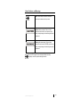
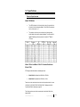
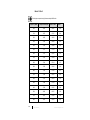
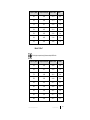
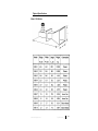
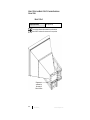
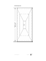
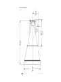
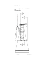
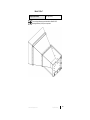
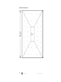
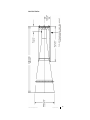
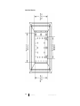
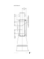
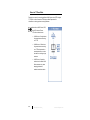
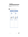
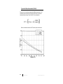
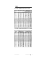
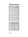
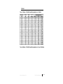
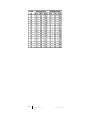
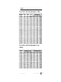
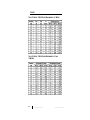
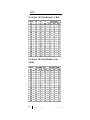
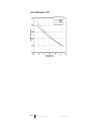
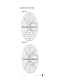
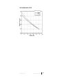
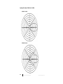
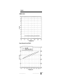
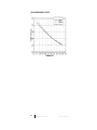
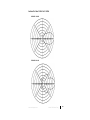
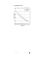
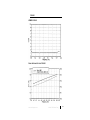
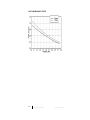
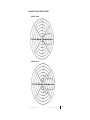
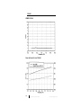
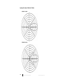
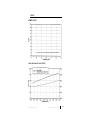
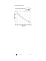
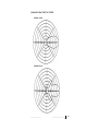
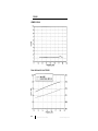
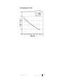
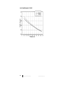
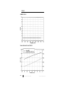
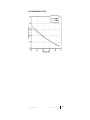
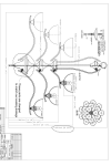
Model 3160 Series Pyramidal Horn Antenna User Manual ETS-Lindgren Inc. reserves the right to make changes to any product described herein in order to improve function, design, or for any other reason. Nothing contained herein shall constitute ETS-Lindgren Inc. assuming any liability whatsoever arising out of the application or use of any product or circuit described herein. ETS-Lindgren Inc. does not convey any license under its patent rights or the rights of others. © Copyright 1992–2014 by ETS-Lindgren Inc. All Rights Reserved. No part of this document may be copied by any means without written permission from ETS-Lindgren Inc. Trademarks used in this document: The ETS-Lindgren logo is a registered trademark of ETS-Lindgren Inc. Revision Record | MANUAL, 3160 SERIES | Part #399185, Rev. F ii Revision Description Date A Initial Release February, 1992 B Edits/updates October, 2002 C Edits/updates July, 2003 D Rebrand July, 2010 E Added 3160-u5 and 3160-u7 specifications November, 2011 F Added calculated gain formulas and data July, 2014 www.ets-lindgren.com Table of Contents Notes, Cautions, and Warnings .............................................. vii 1.0 Introduction .......................................................................... 9 Tripod Options .......................................................................................... 11 ETS-Lindgren Product Information Bulletin ............................................... 12 2.0 Maintenance ....................................................................... 13 Annual Calibration .................................................................................... 13 Service Procedures .................................................................................. 14 3.0 Specifications ..................................................................... 15 Electrical Specifications ............................................................................ 15 Model 3160 Series ............................................................................ 15 Model 3160-u5 and Model 3160-u7: Standard Gain Horns Below 1 GHz ..................................................................................... 15 Model 3160-u5 .......................................................................... 16 Model 3160-u7 .......................................................................... 17 Physical Specifications ............................................................................. 19 Model 3160 Series ............................................................................ 19 Model 3160-u5 and Model 3160-u7: Standard Gain Horns Below 1 GHz ..................................................................................... 20 Model 3160-u5 .......................................................................... 20 Model 3160-u7 .......................................................................... 25 4.0 Mounting Instructions ....................................................... 31 3160-09 and 3160-10 Only ....................................................................... 32 3160-09 ............................................................................................ 32 3160-10 ............................................................................................ 32 Mount to 4-TR........................................................................................... 33 Mount to 7-TR and Mast ........................................................................... 34 Mount to 2x2 Boom ................................................................................... 35 5.0 Typical Data ........................................................................ 37 Typical VSWR (3160-06) .......................................................................... 37 Typical Gain and Antenna Factor (3160-06) .............................................. 38 www.ets-lindgren.com iii Calculated Far Field Gain ......................................................................... 39 Geometry of the Horns ...................................................................... 40 Calculated Gain ................................................................................ 40 Typical Half-Power Beamwidth (3160-06) ................................................. 42 6.0 Radiated Emissions Measurements ................................ 43 Measure Ambient Field Strength Values ................................................... 43 Conversion Formulas ................................................................................ 44 Equation 1 ........................................................................................ 44 Equation 2 ........................................................................................ 45 Equation 3 ........................................................................................ 45 Equation 4 ........................................................................................ 45 Equation 5 ........................................................................................ 45 Equation 6 ........................................................................................ 46 Equation 7 ........................................................................................ 46 Equation 8 ........................................................................................ 46 Equation 9 ........................................................................................ 46 Appendix A: Warranty ............................................................. 47 Appendix B: Power Requirements ......................................... 49 3160-01 .................................................................................................... 50 Table 1: Model 3160-01 Power Requirements at 1 Meter.................. 50 Table 2: Model 3160-01 Power Requirements at 3 and 10 Meters .... 50 3160-02 .................................................................................................... 51 Table 3: Model 3160-02 Power Requirements at 1 Meter.................. 51 Table 4: Model 3160-02 Power Requirements at 3 and 10 Meters .... 51 3160-03 .................................................................................................... 52 Table 5: Model 3160-03 Power Requirements at 1 Meter.................. 52 Table 6: Model 3160-03 Power Requirements at 3 and 10 Meters .... 52 3160-04 .................................................................................................... 53 Table 7: Model 3160-04 Power Requirements at 1 Meter.................. 53 Table 8: Model 3160-04 Power Requirements at 3 and 10 Meters .... 53 3160-05 .................................................................................................... 55 Table 9: Model 3160-05 Power Requirements at 1 Meter.................. 55 Table 10: Model 3160-05 Power Requirements at 3 and 10 Meters .. 55 3160-06 .................................................................................................... 56 iv www.ets-lindgren.com Table 11: Model 3160-06 Power Requirements at 1 Meter ................ 56 Table 12: Model 3160-06 Power Requirements at 3 and 10 Meters .. 56 3160-07 .................................................................................................... 57 Table 13: Model 3160-07 Power Requirements at 1 Meter ................ 57 Table 14: Model 3160-07 Power Requirements at 3 and 10 Meters .. 57 3160-08 .................................................................................................... 58 Table 15: Model 3160-08 Power Requirements at 1 Meter ................ 58 Table 16: Model 3160-08 Power Requirements at 3 and 10 Meters .. 58 3160-09 .................................................................................................... 59 Table 17: Model 3160-09 Power Requirements at 1 Meter ................ 59 Table 18: Model 3160-09 Power Requirements at 3 and 10 Meters .. 59 3160-10 .................................................................................................... 60 Table 19: Model 3160-10 Power Requirements at 1 Meter ................ 60 Table 20: Model 3160-10 Power Requirements at 3 and 10 Meters .. 60 Appendix C: Model 3160 Series Data ..................................... 61 3160-01 .................................................................................................... 61 VSWR: 3160-01 ................................................................................ 61 Gain / Antenna Factor: 3160-01 ........................................................ 61 Half-Power Beamwidth: 3160-01 ....................................................... 62 Antenna Pattern: 3160-01 at 1.2 GHz ............................................... 63 3160-02 .................................................................................................... 64 VSWR: 3160-02 ................................................................................ 64 Gain / Antenna Factor: 3160-02 ........................................................ 64 Half-Power Beamwidth: 3160-02 ....................................................... 65 Antenna Pattern: 3160-02 at 1.41 GHz ............................................. 66 3160-03 .................................................................................................... 67 VSWR: 3160-03 ................................................................................ 67 Gain / Antenna Factor: 3160-03 ........................................................ 67 Half-Power Beamwidth: 3160-03 ....................................................... 68 Antenna Pattern: 3160-03 at 2.15 GHz ............................................. 69 3160-04 .................................................................................................... 70 VSWR: 3160-04 ................................................................................ 70 Gain / Antenna Factor: 3160-04 ........................................................ 70 Half-Power Beamwidth: 3160-04 ....................................................... 71 Antenna Pattern: 3160-04 at 3.3 GHz ............................................... 72 www.ets-lindgren.com v 3160-05 .................................................................................................... 73 VSWR: 3160-05 ................................................................................ 73 Gain / Antenna Factor: 3160-05 ........................................................ 73 Half-Power Beamwidth: 3160-05 ....................................................... 74 Antenna Pattern: 3160-05 at 4.9 GHz ............................................... 75 3160-06 .................................................................................................... 76 VSWR: 3160-06 ................................................................................ 76 Gain / Antenna Factor: 3160-06 ........................................................ 76 Half-Power Beamwidth: 3160-06 ....................................................... 77 Antenna Pattern: 3160-06 at 7.0 GHz ............................................... 78 3160-07 .................................................................................................... 79 VSWR: 3160-07 ................................................................................ 79 Gain / Antenna Factor: 3160-07 ........................................................ 79 Half-Power Beamwidth: 3160-07 ....................................................... 80 Antenna Pattern: 3160-07 at 10.3 GHz ............................................. 81 3160-08 .................................................................................................... 82 VSWR: 3160-08 ................................................................................ 82 Gain / Antenna Factor: 3160-08 ........................................................ 82 Half-Power Beamwidth: 3160-08 ....................................................... 83 Antenna Pattern: 3160-08 at 15.2 GHz ............................................. 84 3160-09 .................................................................................................... 85 VSWR: 3160-09 ................................................................................ 85 Gain / Antenna Factor: 3160-09 ........................................................ 85 Half-Power Beamwidth: 3160-09 ....................................................... 86 Antenna Pattern: 3160-09 at 22.0 GHz ............................................. 87 3160-10 .................................................................................................... 88 VSWR: 3160-10 ................................................................................ 88 Gain / Antenna Factor: 3160-10 ........................................................ 88 Half-Power Beamwidth: 3160-10 ....................................................... 89 Antenna Pattern: 3160-10 at 33.0 GHz ............................................. 90 vi www.ets-lindgren.com Notes, Cautions, and Warnings Note: Denotes helpful information intended to provide tips for better use of the product. Caution: Denotes a hazard. Failure to follow instructions could result in minor personal injury and/or property damage. Included text gives proper procedures. Warning: Denotes a hazard. Failure to follow instructions could result in SEVERE personal injury and/or property damage. Included text gives proper procedures. See the ETS-Lindgren Product Information Bulletin for safety, regulatory, and other product marking information. www.ets-lindgren.com vii This page intentionally left blank. viii www.ets-lindgren.com 1.0 Introduction The ETS-Lindgren Model 3160 Series Pyramidal Horn Antenna is a series of pyramidal standard gain horn antennas designed specifically for utilization in emissions and immunity testing over the frequency range of 1 GHz to 40 GHz. The Model 3160 Series includes models 3160-01 through 3160-10. Each Model 3160 Series antenna is linearly polarized and has medium gain, wide half-power beamwidth (HPBW) in both the horizontal and vertical planes, low VSWR over the recommended operating frequency range, and constant antenna factors so that the antennas can be used without looking up tables or charts. The performance of the Model 3160 Series is precise and predictable through design parameters. Both input and output are well matched to 50 Ω and 377 Ω respectively. Comparisons of measured versus computed gain and antenna factors have been found to be within ±0.5dB. The Model 3160 Series antennas are considered to be the standard reference of measurements above 1 GHz, as is the resonant dipole for measurements below 1 GHz. Each Model 3160 Series antenna is ruggedly constructed for good electromagnetic performance. Models 3160-01 through 3160-06 are welded using precise toolings and aluminum sheet metal. Models 3160-07 and 3160-08 are investment casted using an aluminum compound. Models 3160-09 and 3160-10 are electroformed using deposition of copper at a rate of 0.001 inch/hour for the highest precision available. Models 3160-01 through 3160-08 are conversion coated and painted for protection against corrosion and changes in the weather. www.ets-lindgren.com Introduction 9 Each Model 3160 Series antenna comes completely assembled with a high performance, low VSWR, coax-to-waveguide adapter. Below 18 GHz, the transition from coax to waveguide is made using a female Precision N connector. Above 18 GHz, the transition uses female K connectors. The coax-to-waveguide adapters are the only power-limiting component, and can be removed if high fields are desired. For this purpose, the RF generator must be equipped with waveguide ports. In such a configuration, fields in excess of 10,000 V/m at 10 meters can be obtained. Each Model 3160 Series antenna comes with a standard 1/4–20 mount. Horizontal and vertical polarizations are obtained by rotating the antennas from one position on the mount to the other. The mounts have been placed so as not to interfere with incoming electromagnetic energy. For the variety of mounting options available for the Model 3160 Series, see Mounting Instructions on page 20. The Model 3160 Series may be used for either transmission or reception. The 50 ohm input impedance is well-matched for generating high electric fields with little power reflected back to the amplifier, reducing the chance of saturation. As a receiver, the antennas are matched to free space (377 ohms). Typical performance data is provided beginning on page 37. Methods for radiated emissions measurement are described on page 43. For TEMPEST applications, all Model 3160 Series antennas, especially models 3160-03 and up, can be mounted on standard 12-, 18-, or 24-inch reflector dishes. The resulting antenna factor is usually about 20 dB lower than that of the antennas by themselves. However, the HPBW drops to less than 50 and the far field distance increases drastically making near field performance less predictable. 10 Introduction www.ets-lindgren.com Tripod Options Do not mount the Model 3160-01 or Model 3160-02 to a 4-TR. ETS-Lindgren offers the following non-metallic, non-reflective tripods for use at both indoor and outdoor EMC test sites. 4-TR Tripod—Constructed of linen phenolic and delrin, designed with an adjustable center post for precise height adjustments. Maximum height is 2.0 m (80.0 in), and minimum height is 94 cm (37.0 in). This tripod can support up to an 11.8 kg (26.0 lb) load. 7-TR Tripod—Constructed of PVC and fiberglass components, providing increased stability for physically large antennas. The unique design allows for quick assembly, disassembly, and convenient storage. Allows several different configurations, including options for manual or pneumatic polarization. Quick height adjustment and locking wheels provide ease of use during testing. Maximum height is 2.17 m (85.8 in), with a minimum height of 0.8 m (31.8 in). This tripod can support a 13.5 kg (30 lb) load. www.ets-lindgren.com Introduction 11 ETS-Lindgren Product Information Bulletin See the ETS-Lindgren Product Information Bulletin included with your shipment for the following: 12 Warranty information Safety, regulatory, and other product marking information Steps to receive your shipment Steps to return a component for service ETS-Lindgren calibration service ETS-Lindgren contact information Introduction www.ets-lindgren.com 2.0 Maintenance Before performing any maintenance, follow the safety information in the ETS-Lindgren Product Information Bulletin included with your shipment. WARRANTY Maintenance of the Model 3160 Series is limited to external components such as cables or connectors. If you have any questions concerning maintenance, contact ETS-Lindgren Customer Service. When not in use, the Model 3160 Series Pyramidal Horn Antenna should be stored on a shelf face down to keep dust out of the feed areas. If the Model 3160 Series is used outdoors, the antennas should be checked for water accumulations. Water has a high dielectric constant and can alter performance. If an antenna is dropped, the feed/horn joint should be checked for misalignment. Annual Calibration The electromagnetic performance of the Model 3160 Series is almost exclusively dependent on the physical dimensions of the horns. Comparisons with computed gain and antenna factor result in differences within 1 dB. Therefore, it is not necessary to calibrate Model 3160 Series antennas; only a mechanical check is required to guarantee performance. However, if calibration is required, see the Product Information Bulletin included with your shipment for information on ETS-Lindgren calibration services. www.ets-lindgren.com Maintenance 13 Service Procedures For the steps to return a system or system component to ETS-Lindgren for service, see the Product Information Bulletin included with your shipment. 14 Maintenance www.ets-lindgren.com 3.0 Specifications Electrical Specifications MODEL 3160 SERIES The VSWR indicated in the following table is that of the pyramidal horn antenna and coax-to-waveguide adapter. The VSWR of the antenna by itself is of the order of 1.1:1. The maximum continuous power indicated in the following table is mainly limited by the coax-to-waveguide adapter. The antenna itself is 4 capable of handling continuous power on the order of 10 Watts to 7 10 Watts. MODEL 3160-U5 AND MODEL 3160-U7: STANDARD GAIN HORNS BELOW 1 GHZ ETS-Lindgren also offers these two standard gain horns: Model 3160-u5—Operates from 500 MHz to 750 MHz. Model 3160-u7—Operates from 750 MHz to 1 GHz. These horns require customized mounts due to their large physical size; for more information see the Model 3160-u5 and Model 3160-u7 drawings provided in Physical Specifications beginning on page 20. The following sections provide the computed gain for the Model 3160-u5 and Model 3160-u7. www.ets-lindgren.com Specifications 15 MODEL 3160-U5 Far field gain computed using full wave analysis MW Studio. 16 Frequency (MHz) Computed Gain (dBi) Numeric Gain 500 16.42 43.87 1.48 510 16.76 47.37 1.43 520 16.95 49.52 1.35 530 17.02 50.40 1.24 540 17.06 50.80 1.13 550 17.11 51.44 1.07 560 17.21 52.56 1.12 570 17.32 53.93 1.17 580 17.42 55.19 1.17 590 17.50 56.25 1.13 600 17.58 57.30 1.07 610 17.68 58.55 1.06 620 17.78 60.01 1.13 630 17.88 61.44 1.18 640 17.96 62.55 1.18 650 18.02 63.37 1.16 670 18.18 65.80 1.10 680 18.33 68.09 1.08 Specifications VSWR www.ets-lindgren.com Frequency (MHz) Computed Gain (dBi) Numeric Gain VSWR 690 18.50 70.79 1.09 700 18.64 73.11 1.13 710 18.71 74.30 1.16 720 18.70 74.13 1.16 760 18.65 73.22 1.14 740 18.53 71.30 1.12 750 18.50 70.86 1.10 MODEL 3160-U7 Far field gain computed using full wave analysis MW Studio. Frequency (MHz) Computed Gain (dBi) Numeric Gain VSWR 750 14.64 29.09 1.35 760 14.77 29.99 1.33 770 14.90 30.91 1.34 780 15.03 31.84 1.38 790 15.15 32.77 1.41 800 15.26 33.60 1.42 810 15.35 34.27 1.38 820 15.41 34.77 1.31 830 15.46 35.17 1.21 www.ets-lindgren.com Specifications 17 18 Frequency (MHz) Computed Gain (dBi) Numeric Gain VSWR 840 15.51 35.57 1.11 850 15.57 36.07 1.07 860 15.64 36.67 1.11 870 15.73 37.39 1.16 890 15.93 39.14 1.19 900 16.04 40.15 1.18 910 16.15 41.24 1.16 920 16.27 42.35 1.12 930 16.38 43.45 1.09 940 16.49 44.53 1.08 950 16.59 45.56 1.11 960 16.68 46.51 1.16 970 16.76 47.37 1.22 980 16.82 48.12 1.26 990 16.88 48.76 1.28 1000 16.93 49.37 1.27 Specifications www.ets-lindgren.com Physical Specifications MODEL 3160 SERIES www.ets-lindgren.com Specifications 19 MODEL 3160-U5 AND MODEL 3160-U7: STANDARD GAIN HORNS BELOW 1 GHZ MODEL 3160-U5 Weight (approximate): 95.3 kg (210.0 lb) Two mounting subframes with hardware are provided with the Model 3160-u5. Hardware for customer mount is not provided. 20 Specifications www.ets-lindgren.com Model 3160-u5 Aperture View www.ets-lindgren.com Specifications 21 Model 3160-u5 Side View 22 Specifications www.ets-lindgren.com Model 3160-u5 Back View www.ets-lindgren.com Specifications 23 Model 3160-u5 Bottom View Clearance holes (7) in bottom of subframe are for M8 or 3/8–16 bolts. Hardware not provided. 24 Specifications www.ets-lindgren.com MODEL 3160-U7 Weight (approximate): 32.7 kg (72.0 lb) Two mounting platforms are provided with the Model 3160-u7. Mounting fasteners (1/4–20) are not provided. www.ets-lindgren.com Specifications 25 Model 3160-u7 Aperture View 26 Specifications www.ets-lindgren.com Model 3160-u7 Side View www.ets-lindgren.com Specifications 27 Model 3160-u7 Back View 28 Specifications www.ets-lindgren.com Model 3160-u7 Bottom View www.ets-lindgren.com Specifications 29 This page intentionally left blank. 30 Specifications www.ets-lindgren.com 4.0 Mounting Instructions Before connecting any components, follow the safety information in the ETS-Lindgren Product Information Bulletin included with your shipment. The Model 3160 Series antennas are precision measurement devices. Handle your antenna with care. Horizontal and vertical polarizations can be achieved by rotating the antenna from one mount to the other. The Model 3160-u5 and Model 3160-u7 horns require customized mounts due to their large physical size; for more information see the Model 3160-u5 and Model 3160-u7 drawings provided in Physical Specifications beginning on page 20. The Model 3160 Series Pyramidal Horn Antenna is equipped with a standard 1/4–20 mount. The mount is placed so as not to interfere with incoming electromagnetic energy. Once mounted, remove the red cover from the Type N connector and attach a cable between the antenna and a transmitting/receiving RF device. Rotate the antenna for horizontal and vertical polarizations as needed. www.ets-lindgren.com Mounting Instructions 31 3160-09 and 3160-10 Only The 3160-09 and 3160-10 antennas ship with a supplemental mount that may be used with the 4-TR Tripod, 7-TR Tripod, mast, and 2x2 boom. 3160-09 103255 Clamping Block 103256 Mounting Bracket 3160-10 103253 Clamping Block 103254 Mounting Bracket 32 Mounting Instructions www.ets-lindgren.com Mount to 4-TR Do not mount the Model 3160-01 or Model 3160-02 to a 4-TR. Model 3160 Series antennas mount directly to an ETS-Lindgren 4-TR Tripod; no additional hardware is required. Secure the mount onto the 4-TR by tightening the1/4–20 UNC mount knob. www.ets-lindgren.com Mounting Instructions 33 Mount to 7-TR and Mast Following is an option for mounting the Model 3160 Series onto an ETS-Lindgren 7-TR Tripod or mast. Contact the ETS-Lindgren Sales Department for information on ordering optional mounting hardware. Mast refers to 2070 Series, 2075, and 2175 Antenna Towers. 7-TR refers to these booms: 109042 boom— Straight boom; for general antenna mounting on a 7-TR 108983 boom— Offset boom; for general antenna mounting on a 7-TR with pneumatic or manual polarization; can also be used to mount stinger-type antennas 108507 boom—Centerline rotation boom for Model 3106 Series antennas only; when changing polarization, maintains centerline rotation 34 Mounting Instructions www.ets-lindgren.com Mount to 2x2 Boom Following are options for mounting the Model 3160 Series onto a 2x2 boom. Contact the ETS-Lindgren Sales Department for information on ordering optional mounting hardware. 2x2 boom refers to a typical 2-inch by 2-inch boom. www.ets-lindgren.com Mounting Instructions 35 This page intentionally left blank. 36 Mounting Instructions www.ets-lindgren.com 5.0 Typical Data Following is typical electromagnetic performance data for the Model 3160 Series Pyramidal Horn Antenna, using Model 3160-06 data as representative of the series. See Model 3160 Series Data on page 61 for data for all Model 3160 Series antennas. Typical VSWR (3160-06) The following shows the antenna/coax-to-waveguide adapter assembly. www.ets-lindgren.com Typical Data 37 Typical Gain and Antenna Factor (3160-06) Following is a plot of computed and measured gain and antenna factor versus frequency. The measured and computed results are within 3 dB, which is typical of pyramidal horns. Differences are attributed to imperfections in the measurements setup. The left vertical scale is for the gain measured in dBi, and -1 the right vertical scale is for the antenna factor in dB(m ). The antenna factor spans only 0.6 dB from minimum to maximum; therefore, it may be considered constant over the entire frequency band without loss of accuracy. The gain is computed from the antenna factor using: G(dB) = 20 log (fGHz ) - AFdB(m-1) + 30.22 38 Typical Data www.ets-lindgren.com Calculated Far Field Gain The gain of a pyramidal horn (linear gain, not dB) is calculated as follows: [ ( ) ( )] [( ( ) ( )) ( ( ) ( )) ] Where √ ( √ √ ) And √ √ ( √ ) Finally √ And C(x) and S(x) are the Fresnel Cosine Integral and the Fresnel Sine Integral functions. www.ets-lindgren.com Typical Data 39 GEOMETRY OF THE HORNS units in cm or degrees aperture waveguide flare Flares E and H angle H angle E A B a b L lE lH 3160-u5 41 36 155.42 120.88 35.56 17.78 159.16 253.11 171.98 3160-u7 32 28 80.41 59.99 25.07 12.38 96.14 167.07 108.31 3160-01 32 28 62.58 49.87 19.56 9.78 75.00 130.35 90.44 3160-02 32 27 52.82 39.55 16.51 8.26 64.00 111.20 72.46 3160-03 31 28 34.00 26.00 10.92 5.46 41.52 70.93 48.64 3160-04 23 20 23.50 17.50 7.21 3.40 40.00 67.71 43.86 3160-05 23 20 16.01 11.60 5.07 2.52 26.85 46.70 29.00 3160-06 23 20 11.59 8.59 3.49 1.58 20.00 34.18 21.92 3160-07 24 22 7.60 5.80 2.29 1.02 12.62 20.37 14.06 3160-08 29 24 5.01 3.73 1.50 0.71 7.02 11.91 7.51 3160-09 30 26 3.54 2.56 0.95 0.32 4.69 7.96 5.00 3160-10 31 26 2.46 1.77 0.60 0.24 3.13 5.51 3.27 CALCULATED GAIN 3160-u5 3160-u7 3160-01 3160-02 Frequency G Frequency G Frequency G Frequency G 0.5 16.42 0.75 14.5549 0.96 14.8231 1.12 14.4253 0.55 17.07 0.8 15.0711 1.06 15.6164 1.236 15.2158 0.6 17.64 0.85 15.5505 1.16 16.3255 1.352 15.9232 0.65 18.13 0.9 15.997 1.26 16.9633 1.468 16.5601 0.7 18.16 0.95 16.4139 1.36 17.5397 1.584 17.1364 0.75 18.92 1 16.8039 1.46 18.0626 1.7 17.6598 40 Typical Data www.ets-lindgren.com 3160-03 3160-04 3160-05 3160-06 Frequency G Frequency G Frequency G Frequency G 1.7 14.34 2.6 14.811 3.95 14.9746 5.85 15.6617 1.88 15.1526 2.87 15.6315 4.33 15.7343 6.32 16.2986 2.06 15.8791 3.14 16.371 4.71 16.4232 6.79 16.8847 2.24 16.5331 3.41 17.0425 5.09 17.09 7.26 17.4266 2.42 17.1247 3.68 17.6558 5.47 17.6294 7.73 17.9293 2.6 17.6622 3.95 18.2182 5.85 18.161 8.2 18.3973 3160-07 3160-08 3160-09 3160-10 Frequency G Frequency G Frequency G Frequency G 8.2 15.0692 12.4 14.8536 18 14.9048 26.5 15.0323 9.04 15.8748 13.52 15.5532 19.7 15.9601 29.2 15.7974 9.88 16.6011 14.64 16.1886 21.4 16.2776 31.9 16.4806 10.72 17.2604 15.76 16.7687 23.1 16.8683 34.6 17.0941 11.56 17.8623 16.88 17.3006 24.8 17.4065 37.3 17.6474 12.4 18.4142 18 17.7898 26.5 17.8984 40 18.148 www.ets-lindgren.com Typical Data 41 Typical Half-Power Beamwidth (3160-06) Following is a plot of the half-power beamwidth (HPBW) versus frequency. The information provides the size of the Equipment Under Test (EUT) that can be illuminated without scanning. The size of the EUT can be obtained as: EUT = 2 [ Distance · tan ( HPBW )] 2 Distance is the distance between the EUT and the aperture of the antenna 42 Typical Data www.ets-lindgren.com 6.0 Radiated Emissions Measurements Measure Ambient Field Strength Values 1. Install the antenna where measured field strength values are desired. 2. Adjust the desired orientation of the antenna for both bore site direction and polarization. 3. Connect the output connector of the antenna to the input of the receiving system using a low VSWR, low loss coaxial cable. The Model 3160 Series Pyramidal Horn Antennas are designed for receiving systems having 50 Ω input impedance. Other values of receiving system input impedance will require correction for the difference in impedance mismatch. 4. Set desired measurement frequency on the receiving system. Make sure that the selected frequency is one that can be used with the antenna that is connected to the system. 5. Measure the RF voltage, Va, referenced to the input port of the receiving system. The units of the measurement should be in decibels referenced to 1 microvolt, dB(µV). If the units of measurements are millivolts, they should be converted to dB(µV) by: Va 20 log 10 ( RF voltage in microvolts ) Va 20 log 10 Vd 6. Determine the field strength at the frequency of observation by adding the voltage reading on the receiving system in dB(µV) to the -1 antenna factor in dB(m ): RF Voltage, dB(µV) + Antenna Factor, dB(m-1) = Field Strength, dB(µV/m) Ea = Va + AF www.ets-lindgren.com Radiated Emissions Measurements 43 The losses of the coaxial cable, Ac , should be included in the computations. In this case, the previous equation becomes: RF Voltage, dB(µV) + Cable Loss, dB + Antenna Factor, DB(m-1) = Field Strength, dB(µV/m) Ea = Va + Ac + AF Conversion Formulas Following are some useful conversion formulas, including how the constants are obtained: EQUATION 1 dBm=dB(V)-107 The power is related to the voltage and the system impedance as: P V2 R In a 50 Ω system, the previous equation becomes: 10 log10 P 20 log10 V 10 log10 (50) Converting from dB to dBm for power and from dB(V) to dB(µV) for voltage, the overall constant becomes: 30 120 10 log10 ( 50 ) 107 44 Radiated Emissions Measurements www.ets-lindgren.com EQUATION 2 dB(mW /m2) = dB(V/m)-115.8 The constant in this equation is obtained by considering the 2 Poynting vector which relates the power density in (W/m ) to the electric field strength in (V/m) by: P= E 2 Where η is the free space characteristic impedance equal to 120π Ω. Transforming the previous questions to decibels and using the 2 2 appropriate conversion factors to convert dB(W/m ) to dB(mW/m ) for power density and dB(V/m) to dB(µV/m) for the electric field, the constant becomes: 30 120 10 log10 (120) 115.8 EQUATION 3 dB(V/m) = dB(V) + AF EQUATION 4 V/m = 10 dB ( V/m)-120 20 EQUATION 5 dB (A/m) = dB(V/m) - 51.5 The magnetic field strength is related to the electric field strength via the characteristic impedance of free space. When the transformation is made to decibels, the constant becomes: www.ets-lindgren.com Radiated Emissions Measurements 45 20 log 10 (120 ) 51. 5 EQUATION 6 A/m = 10 dB ( A/m)-120 20 EQUATION 7 dB(W/m2) = 10 log (V/m A/m) EQUATION 8 dB(mW/m2) = dB(W/m2) + 30.0 EQUATION 9 dB(pT) = dB(A/m) + 2.0 The magnetic flux density B in (T) is related to the magnetic field strength H in (A/m) by the permeability of the medium in (H/m). For -7 free space, the permeability is µo = 4π.10 H/m. Converting from (T) to (pT) and from (A/m) to (µA/m) and taking the log, the constant becomes: 240 120 20 log 10 ( 4 10 7 ) 2. 0 46 Radiated Emissions Measurements www.ets-lindgren.com Appendix A: Warranty See the Product Information Bulletin included with your shipment for the complete ETS-Lindgren warranty for your Model 3160 Series. DURATION OF WARRANTIES FOR MODEL 3160 SERIES All product warranties, except the warranty of title, and all remedies for warranty failures are limited to two years. Product Warranted Duration of Warranty Period Model 3160 Series Pyramidal Horn Antenna 2 Years www.ets-lindgren.com Warranty 47 This page intentionally left blank. 48 Warranty www.ets-lindgren.com Appendix B: Power Requirements The Model 3160 Series Pyramidal Horn Antenna is an efficient transmitting antenna, capable of generating high electric field strengths using little power. For a given electric field strength, the required power can be computed using the transmission equation: Power Transmitted= Pt (Field Strength ) 2 ( Distance in meters) 2 (30 Numeric Gain ) 2 E R2 30 g The typical power requirements in Watts for the 3161-06 are shown in Table 11 Table 12 on page 56. Distance is measured from the aperture of the antenna. The maximum continuous power that can be applied is 250 W, and the maximum peak power is 8 kW. For example, to generate an electric field equal to 100 V/m at a distance of 3 meters at a frequency of 6.25 GHz, the calibration antenna -1 factor read from Table 1 is 29.9 dB(m ). The gain in dB is computed using: G(dB)=20 log(FGHz ) – AF + 30.22 G(dB)=20 log(6.25) – 29.9 + 30.22 = 16.2 The numeric gain is obtained as: g = 101.62 = 42.1 Applying this equation, we obtain: www.ets-lindgren.com Power Requirements 49 3160-01 TABLE 1: MODEL 3160-01 POWER REQUIREMENTS AT 1 METER TABLE 2: MODEL 3160-01 POWER REQUIREMENTS AT 3 AND 10 METERS 50 Power Requirements www.ets-lindgren.com 3160-02 TABLE 3: MODEL 3160-02 POWER REQUIREMENTS AT 1 METER TABLE 4: MODEL 3160-02 POWER REQUIREMENTS AT 3 AND 10 METERS www.ets-lindgren.com Power Requirements 51 3160-03 TABLE 5: MODEL 3160-03 POWER REQUIREMENTS AT 1 METER TABLE 6: MODEL 3160-03 POWER REQUIREMENTS AT 3 AND 10 METERS 52 Power Requirements www.ets-lindgren.com 3160-04 TABLE 7: MODEL 3160-04 POWER REQUIREMENTS AT 1 METER TABLE 8: MODEL 3160-04 POWER REQUIREMENTS AT 3 AND 10 METERS www.ets-lindgren.com Power Requirements 53 54 Power Requirements www.ets-lindgren.com 3160-05 TABLE 9: MODEL 3160-05 POWER REQUIREMENTS AT 1 METER TABLE 10: MODEL 3160-05 POWER REQUIREMENTS AT 3 AND 10 METERS www.ets-lindgren.com Power Requirements 55 3160-06 TABLE 11: MODEL 3160-06 POWER REQUIREMENTS AT 1 METER TABLE 12: MODEL 3160-06 POWER REQUIREMENTS AT 3 AND 10 METERS 56 Power Requirements www.ets-lindgren.com 3160-07 TABLE 13: MODEL 3160-07 POWER REQUIREMENTS AT 1 METER TABLE 14: MODEL 3160-07 POWER REQUIREMENTS AT 3 AND 10 METERS www.ets-lindgren.com Power Requirements 57 3160-08 TABLE 15: MODEL 3160-08 POWER REQUIREMENTS AT 1 METER TABLE 16: MODEL 3160-08 POWER REQUIREMENTS AT 3 AND 10 METERS 58 Power Requirements www.ets-lindgren.com 3160-09 TABLE 17: MODEL 3160-09 POWER REQUIREMENTS AT 1 METER TABLE 18: MODEL 3160-09 POWER REQUIREMENTS AT 3 AND 10 METERS www.ets-lindgren.com Power Requirements 59 3160-10 TABLE 19: MODEL 3160-10 POWER REQUIREMENTS AT 1 METER TABLE 20: MODEL 3160-10 POWER REQUIREMENTS AT 3 AND 10 METERS 60 Power Requirements www.ets-lindgren.com Appendix C: Model 3160 Series Data 3160-01 VSWR: 3160-01 GAIN / ANTENNA FACTOR: 3160-01 www.ets-lindgren.com Model 3160 Series Data 61 HALF-POWER BEAMWIDTH: 3160-01 62 Model 3160 Series Data www.ets-lindgren.com ANTENNA PATTERN: 3160-01 AT 1.2 GHZ H-PLANE: 3160-01 E-PLANE: 3160-01 www.ets-lindgren.com Model 3160 Series Data 63 3160-02 VSWR: 3160-02 GAIN / ANTENNA FACTOR: 3160-02 64 Model 3160 Series Data www.ets-lindgren.com HALF-POWER BEAMWIDTH: 3160-02 www.ets-lindgren.com Model 3160 Series Data 65 ANTENNA PATTERN: 3160-02 AT 1.41 GHZ H-PLANE: 3160-02 E-PLANE: 3160-02 66 Model 3160 Series Data www.ets-lindgren.com 3160-03 VSWR: 3160-03 GAIN / ANTENNA FACTOR: 3160-03 www.ets-lindgren.com Model 3160 Series Data 67 HALF-POWER BEAMWIDTH: 3160-03 68 Model 3160 Series Data www.ets-lindgren.com ANTENNA PATTERN: 3160-03 AT 2.15 GHZ H-PLANE: 3160-03 E-PLANE: 3160-03 www.ets-lindgren.com Model 3160 Series Data 69 3160-04 VSWR: 3160-04 GAIN / ANTENNA FACTOR: 3160-04 70 Model 3160 Series Data www.ets-lindgren.com HALF-POWER BEAMWIDTH: 3160-04 www.ets-lindgren.com Model 3160 Series Data 71 ANTENNA PATTERN: 3160-04 AT 3.3 GHZ H-PLANE: 3160-04 E-PLANE: 3160-04 72 Model 3160 Series Data www.ets-lindgren.com 3160-05 VSWR: 3160-05 GAIN / ANTENNA FACTOR: 3160-05 www.ets-lindgren.com Model 3160 Series Data 73 HALF-POWER BEAMWIDTH: 3160-05 74 Model 3160 Series Data www.ets-lindgren.com ANTENNA PATTERN: 3160-05 AT 4.9 GHZ H-PLANE: 3160-05 E-PLANE: 3160-05 www.ets-lindgren.com Model 3160 Series Data 75 3160-06 VSWR: 3160-06 GAIN / ANTENNA FACTOR: 3160-06 76 Model 3160 Series Data www.ets-lindgren.com HALF-POWER BEAMWIDTH: 3160-06 www.ets-lindgren.com Model 3160 Series Data 77 ANTENNA PATTERN: 3160-06 AT 7.0 GHZ H-PLANE: 3160-06 E-PLANE: 3160-06 78 Model 3160 Series Data www.ets-lindgren.com 3160-07 VSWR: 3160-07 GAIN / ANTENNA FACTOR: 3160-07 www.ets-lindgren.com Model 3160 Series Data 79 HALF-POWER BEAMWIDTH: 3160-07 80 Model 3160 Series Data www.ets-lindgren.com ANTENNA PATTERN: 3160-07 AT 10.3 GHZ H-PLANE: 3160-07 E-PLANE: 3160-07 www.ets-lindgren.com Model 3160 Series Data 81 3160-08 VSWR: 3160-08 GAIN / ANTENNA FACTOR: 3160-08 82 Model 3160 Series Data www.ets-lindgren.com HALF-POWER BEAMWIDTH: 3160-08 www.ets-lindgren.com Model 3160 Series Data 83 ANTENNA PATTERN: 3160-08 AT 15.2 GHZ H-PLANE: 3160-08 E-PLANE: 3160-08 84 Model 3160 Series Data www.ets-lindgren.com 3160-09 VSWR: 3160-09 GAIN / ANTENNA FACTOR: 3160-09 www.ets-lindgren.com Model 3160 Series Data 85 HALF-POWER BEAMWIDTH: 3160-09 86 Model 3160 Series Data www.ets-lindgren.com ANTENNA PATTERN: 3160-09 AT 22.0 GHZ H-PLANE: 3160-09 E-PLANE: 3160-09 www.ets-lindgren.com Model 3160 Series Data 87 3160-10 VSWR: 3160-10 GAIN / ANTENNA FACTOR: 3160-10 88 Model 3160 Series Data www.ets-lindgren.com HALF-POWER BEAMWIDTH: 3160-10 www.ets-lindgren.com Model 3160 Series Data 89 ANTENNA PATTERN: 3160-10 AT 33.0 GHZ H-PLANE: 3160-10 E-PLANE: 3160-10 90 Model 3160 Series Data www.ets-lindgren.com