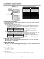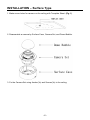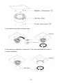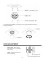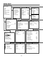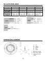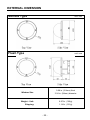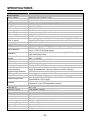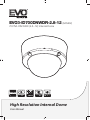
1
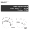
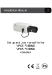
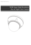
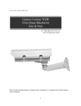
EVO3-ID700DNWDR-2.8-12 (S45462) 700TVL DN WDR (2.8~12) Internal Dome High Resolution Internal Dome User Manual LIMITATION OF LIABILITY THE INFORMATION IN THIS PUBLICATION IS BELIEVED TO BE ACCURATE IN ALL RESPECTS, HOWEVER, WE CANNOT ASSUME RESPONSIBILITY FOR ANY CONSEQUENCES RESULTING FROM THE USE THEREOF. THE INFORMATION CONTAINED HEREIN IS SUBJECT TO CHANGE WITHOUT NOTICE. REVISIONS OR NEW EDITIONS TO THIS PUBLICATION MAY BE ISSUED TO INCORPORATE SUCH CHANGES - ii - WARNING TO REDUCE THE RISK OF FIRE OR ELECTRIC SHOCK, DO NOT EXPOSE THIS PRODUCT TO RAIN OR MOISTURE. DO NOT INSERT ANY METALLIC OBJECTS THROUGH THE VENTILATION GRILLS OR OTHER OPENINGS ON THE EQUIPMEMT. CAUTION EXPLANATION OF GRAPHICAL SYMBOLS A. B. C. D. E. Up Right Down Left Enter The lightning flash with arrowhead symbol, within an equilateral triangle, is intended to alert the user to the presence of uninsulated “dangerous voltage” within the product’s enclosure that may be of sufficient magnitude to constitute a risk of electric shock to persons. The exclamation point within an equilateral is intended to alert the user to the presence of important operating and maintenance (servicing) instructions in the literature accompanying the appliance. - iii - FCC COMPIANCE STATEMENT FCC INFORMATION : This equipment has been tested and found to comply with the limits for a Class A digital device, pursuant to Part 15 of the FCC Rules. These limits are designed to provide reasonable protection against harmful interference when the equipment is operated in a commercial environment. This equipment generates, uses, and can radiate radio frequency energy and, if not installed and used in accordance with the instruction manual, may cause harmful interference to radio communications. Operation of this equipment in a residential area is likely to cause harmful interference in which case the user will be required to correct the interference at his own expense. CAUTION : Changes or modifications not expressly approved by the party responsible for compliance could void the user’s authority to operate the equipment. This Class A digital apparatus complies with Canadian ICES-003. Cet appareil numérique de la classe A est conforme à la norme NMB003 du Canada. CE COMPLIANCE STATEMENT WARNING This is a Class A product. In a domestic environment this product may cause radio interference in which case the user may be required to take adequate measures. - iv - IMPORTANT SAFETY INSTRUCTIONS 1. 2. 3. 4. 5. 6. 7. 8. 9. 10. 11. 12. 13. 14. 15. 16. Read these instructions. Keep these instructions. Heed all warnings. Follow all instructions. Do not use this apparatus near water. Clean only with dry cloth. Do not block any ventilation openings. Install in accordance with the m anufacturer’s instructions. Do not install near any heat sources such as radiators, heat registers, stoves, or other apparatus (including amplifiers) that produce heat. Do not defeat the safety purpose of the polarized or grounding-type plu g. A polarized plug has two blades with one wider than the other. A gro unding type plug has two blades and a third grounding prong. The wid e blade or the third prong are provided for your safety. If the provided p lug does not fit into your outlet, consult an electrician for replacement o f the obsolete outlet. Protect the power cord from being walked on or pinched particularly at plugs, convenience receptacles, and the point where they exit from th e apparatus. Only use attachments/accessories specified by the manufacturer. Use only with the cart, stand, tripod, bracket, or t able specified by the manufacturer, or sold with th e apparatus. When a cart is used, use caution wh en moving the cart/apparatus combination to avoi d injury from tip-over. Unplug this apparatus during lightning storms or when unused for long periods of time. Refer all servicing to qualified service personnel. Servicing is required when the apparatus has bee n damaged in any way, such as power-supply cord or plug is damaged, liquid has been moisture, does not operate normally, or has been drop ped. CAUTION – THESE SERVICING INSTRUCTIONS ARE FOR USE B Y QUALIFIED SERVICE PERSONNEL ONLY. TO REDUCE THE RIS K OF ELECTRIC SHOCK DO NOT PERFORM ANY SERVICING OT HER THAN THAT CONTAINED IN THE OPERATING INSTRUCTION S UNLESS YOU QRE QUALIFIED TO DO SO. Use satisfy clause 2.5 of IEC60950-1/UL60950-1 or Certified/Liste d Class 2 power source only. -v- PRECAUTIONS Before installation, carefully read the manual to ensure correct operation and setup, heeding all warnings and instructions. Do not block any ventilation openings. Install in accordance with the manufacturer's instructions. Ensure manual is kept in good condition for future use. Do not install the device near any heat sources such as radiators, heat registers, stoves, or other equipment (including amplifiers) that produce heat. Only use attachments/accessories specified by the manufacturer. Should any liquid get into the housing, immediately disconnect the device from the power supply and have it checked by authorized personnel before reusing. Do not install the device in a place of high humidity or where exposed to gas or oil. Installation and servicing by authorized personnel only, adhering to local safety regulations. Unless you are an authorized technician, never try to dismantle the device. To avoid electric shock, never remove the screws or covers. If a camera, do not expose the device to radioactivity. It will cause serious damage to the CCD. Use Certified/Listed Class 2 power source only. Cleaning Clean the device with a slightly damp soft cloth. Use a mild household detergent. Never use strong solvents such as thinner or benzene as they might damage the finish of the unit. - vi - TABLE OF CONTENTS CONTENTS OF PACKAGE ------------------------------------------------------------------------- 1 INTRODUCTION --------------------------------------------------------------------------------------- 2 CAMERA CONNECTIONS -------------------------------------------------------------------------- 3 INSTALLATION ----------------------------------------------------------------------------------------- 4 LENS ADJUSTMENT --------------------------------------------------------------------------------- 7 MENU MAP ---------------------------------------------------------------------------------------------- 8 OPERATING CAMERA ------------------------------------------------------------------------------- 10 CAMERA ADJUSTMENT ---------------------------------------------------------------------------- 11 EXTERNAL DIMENSION ---------------------------------------------------------------------------- 21 SPECIFICATIONS ------------------------------------------------------------------------------------- 22 CONTENTS OF PACKAGE Installation of the camera must be performed by qualified service personnel in accordance with all local and national electrical and mechanical codes. Carefully remove the colour camera and its accessories from the carton and verify that they were not damaged in shipment. The content of the package includes: 1. Camera in Housing 2. This Manual 3. Accessory Kit for Installing 4. Drilling guide label -1- INTRODUCTION The camera provided high-quality image using SONY 1/3” CCD and digital signal processing LSIs. Features: 1/3" Super-HADII CCD Super high-resolution (700TVL) Wide Dynamic Range (~x512) Day & Night(Auto, Manual, External, Filter delay, Change level adjust) 0.1Lux(Color), 0.01 Lux(BW) @ F1.2 50IRE Auto Electronic Shutter [1/50(60) ~ 1/100,000] and manual electronic shutter modes [1/50(60) ~ 1/10,000] Sens-Up (~x256) 2D-NR, 3D-NR UDF Function(Ultra Deep Field) Multi Camera Configuration Set (4-Sets/Night Profile, Ext DN Profile) PVA/PVA+ (Personal Video Analytics) Very High Configurable. Various Detection Methods(Motion, Loitering Object, Abandon, Scene Change, Unfocus, Windy Area) Various Zone Event Detection Methods, and Event Area Combinations. 8 Objects Trace, 4 Objects Display Concurrent Processing with All Detections, and All Objects. Two Counting Block. Event String Sending (Editable String) Digital Tracking(Using D-PTZ) Various Detection Area(MAX. 10 area, Line, Rectangle, 4-Point polygonal) Back Light Compensation (EHLC, Auto, Spot) i-Freeze Function(Reduce recording space) Privacy Mask or Mosaic(MAX. 10 area/4-point polygonal/transparency) Digital Image Stabilization. Digital PTZ Digital Effect (H/V reverse, 180 degree rotate, inverse, freeze) White Pixel Removal. Focus Aid Function. Color Rolling Suppression. System Lock (4-character password) Auto and Manual white balance modes Support Line-Lock external synchronization RS-485 Remote camera control User Certified / Listed Class 2 power source only Operates in 12VDC or 24VAC -2- CAMERA CONNECTIONS Connection Cable Description COLOR Description RED WHITE BLUE GREEN YELLOW GRAY BLACK&WHITE BLACK SKY BLUE PINK AC24V/DC12V AC24V/DC12V RS485(-) RS485(+) ALARM OUT DN EXT-IN DN EXT-OUT GND UTP+(Option) UTP- (Option) 1) External Day/Night Control Select Day/Night mode using external equipment, by connecting control lines to the appropriate terminals. DAY&NIGHT EXTERNAL INPUT Switches the cameras D/N mode to either Day or Night based on the input status. Refer to the diagram below. The cameras D/N mode must be set to EXT for this to function. Black GND ● Open contact: DAY Gray DAY&NIGHT INPUT ● Close contact: NIGHT DAY&NIGHT OUTPUT – Open Collector (5V/10mA) The camera turns on an external IR LED Lamp by detecting the sensitivity on the AGC level when the D&N mode is set "AUTO" on the OSD menu of the camera. Black&White DAY&NIGHT OUTPUT Black GND ● 5V/10mA : IR LED ON (NIGHT) ● 0V : IR LED OFF (DAY) ‘ 2) Alarm Out – Open Collector (5V/10mA) Motion detection signals are output through this port. (YELLOW AND GND) Active state is configurable. 3) Power Input Terminal RED & WHITE: These terminals accept 24VAC or 12 VDC. When using 12VDC it is recommended to use a DC power supply that can support an inrush current of 0.35A 4) Camera Control GREEN : RS 485+ BLUE : RS 4855) UTP (Option) Video signal through out the UTP Cable (SKY BLUE(+) & PINK(-)) -3- INSTALLATION – Surface Type 1. Make screw holes for camera on the ceiling with Template Sheet. (Fig. 1) 2. Disassemble a camera by Surface Case, Camera Set, and Dome Bubble. 3. Fix the Camera Set using Anchor(3x) and Screws(3x) to the ceiling. -4- 4. Assemble Camera Set to Surface Case. 5. Assemble Dome Bubble to Camera Set. Turn the Dome Bubble clockwise to complete installation. -5- INSTALLATION – Flush Type 1. Make screw holes for camera on the ceiling with Template Sheet. 2. Disassemble a camera by Surface case, Camera Set, and Dome Bubble. 3. Fix the Camera Set using Anchors(4x) and Screws(4x) to the ceiling -6- 4. Assemble Dome Bubble to Camera Set. Turn the Dome Bubble clockwise to complete installation. LENS ADJUSTMENT Field of view: Adjust setting from Telephoto (T) to wide (W) field of View. Focus: Adjust lens focus from near (N) to infinity. -7- MENU MAP Main Menu WB AE Privacy Mask PVA Picture/DNR Effect System Setup WB AE ATW/Wide ATW/Indoor ATW/Outdoor Fix/Indoor Fix/FL Fix/Outdoor Low Light AGC Sens-Up Suppress Apert Color Mode Full Auto+ UDF Off Low Light WDR Off BLC Off Brightness 50 Mid Off 25 25 WDR Visibility Comb Bal Brightness 2 1 50 System Setup General Setup Tools Lens DC LLC No Ext_Sync Day/Night EXT-I/O Counter General Setup Tools Cam Info System Lock Change PID Title Display Display PVA Motion Loitering Cam ID Title Display Pos Off Off Abandon Scene Change Zone Zone Func Shape MD Event System Config WPC On Focus Aid System Config Zone Env.Setup Display Setup dTracking Setup Motion UnLock Multi-CamSet Video Analytics Communication Cam ID Baud Rate Protocol Event Out Event Strings Off PVA 1 9600 Auto Off Env. Setup 0 Off Rect -8- MD Sens Loiter Time(s) Abandon/Absent Setup Scn Chg Setup 5 30 Privacy Mask Picture/DNR Zone Func Color Transparency Mosaic Frame Shape 0 Off 7 3 Off Off Rect Day/Night Lens Iris Speed Sharpness Resolution 2D-NR 3D-NR Link Motion DNR Demo Color Enh Detection Burst Delay(s) D/N Thre D>N N>D 50 08 Mid 2 2 On Freeze d-Effect Nega DIS dPTZ Preset i-Freeze Off Off Off Off 1 EXT-I/O Inter Off 5 Mid 0.08 0.30 Focus Aid SHT(S) Gain/dB Zoom Adj FAD Max FAD Effect D/N OUT D/N Out Set AUX0 NA ALARM OUT Alarm Out Set AUX1 NA D/N IN D/N Counter 1/2000 18 OFF Stop 0 0 Alarm On Zero Preset Cnt1 Preset Cnt2 Reset TextOut to Comm dTracking Setup Display Setup Alarm Counter Zone Area Moving Object Loitering Abandon/Absent 0 Off Off Off Off Off Off All Object Loitering Abandon Zone Off Off Off Off -9- 0 Off NA NA NA DC AUTO IRIS LENS 2.6-6mm Image Size Focal Length Ape. Ratio Angular Field of View (Degree) 4-9mm 1/3” CCD 2.6-6.0mm 1 : 1.6 2.8~12mm 1/3" CCD 5% 4.0-9.0mm 5% DIAGONAL 2.6mm : 134.6 6mm : 59.2 1 : 1.6 5% 5% DIAGONAL 4mm : 92.4 9mm : 39.2 6-50mm 1/3" CCD 2.8-12mm 1 : 1.4 1/3" CCD 5% 5% 6.0-50mm 1 : 1.6 DIAGONAL 2.8mm : 119.9 12mm : 28.8 5% 6.9% DIAGONAL 6mm : 58.6 50mm : 7.1 OPERATING CAMERA A. B. C. D. E. Up Right Down Left Enter F. BNC/UTP Switch G. Test Video Output H. External AD Key Input - 10 - <Remarks> 1) Menu: Represent present menu subject on top of screen. In case of used Multi-Camset, Represent CAM ID and “camset” name included. Common Headers: : Currently active menu item is displayed. Move by Up/Down keys. : There is sub-menu. Press Enter key going to sub-menu. : Indicates the selected menu item. Item: Displays the current control item you are adjusting. Item: Disabled menu item or can’t adjust. 2) Bottom Line Control Bar. Exit: Exit menu mode. Pop-up menu rise when configuration changed. - Overwrite: Save the changed data to save area. - Restore: Cancel the changes. Read from save area. - Cancel: Return to menu. Load: Load saved data - Default: Load default configuration from default area. - Backup: Load saved configuration from backup area. - Cancel: Return to menu. Save: Save current configuration. - Save: Save current configuration to save area. - Backup: Copy configurations to backup area. - Cancel: Return to menu. Back : Return to previous menu. NOTE: * There are 4 types of configuration area. Editing Area(No Save), Default(Read Only). Save Area(Use on Start), Backup * Don’t Power off while doing Save, Load, Backup, Overwrite CAMERA ADJUSTMENT <White Balance> 1) ATW/Wide Mode: No limits in the range of color temperature. 2) ATW/Indoor Mode: Suitable for low color temperature. - CRS (Color Rolling Suppression) Mode supported. NOTE: * When the CRS is selected, it will be processed in the following order: Checking Condition: Checking current environment within the range. Checking Variation: Measure color rolling range during 30 seconds. User can stop this action. No Need CRS: Variation is low. There is no need to use CRS function. Force CRS: Even if color variation is low, use CRS function. - ATW Range: Adjust AWB Range. - Convergence Shift: Adjust AWB target. R Variation: Represent blue variation. B Variation: Represent red variation. 3) ATW/Outdoor Mode: Suitable for high color temperature (natural light). 4) Fix/Indoor Mode: Fixed color temperature (3200 ºK) mode, for indoor environment. - R: Adjust red color. - 11 - - B: Adjust blue color. - Push/Set: Tracking WB of current screen and represent R, B values. - Default: Restore R, B default values. 5) Fix/FL Mode: Fixed color temperature mode (fluorescent lamp environment). 6) Fix/Outdoor Mode: Fixed color temperature (6300 ºK) mode, for outdoor environment. <Auto Exposure> NOTE: * MIN_SHT (Minimum shutter speed): NTSC: 1/60sec/PAL: 1/50sec * MAX_SHT (Maximum shutter speed): 1/100000 sec * FLC_SHT (Flickerless shutter speed): NTSC: 1/100sec/PAL: 1/120sec 1) AE Mode - Full Auto: DC Lens or Video Lens – Fix shutter speed to MIN_SHT. Manual Lens - Operating as shutter mode. - Full Auto+: shutter (1/50~1/250) + iris - Fast SHT (Fast shutter mode): Adjust range - 1/250~1/10000 - SHT Fix (Shutter Fix Mode): Shutter speed is fixed at a given value. NOTE: * If lighting is not enough, noise may be increased. * If lighting is enough using AGC maximum, automatically decreases shutter speed. 2) UDF (Ultra Deep Field) Depending on lighting conditions and motion state, automatically adjusts AE and DNR. Normally in low light environment, Sens-up feature may miss the movement of objects and high AGC value increases the noise. UDF function effectively improves this phenomenon. NOTE: * No Motion: Noise removal mode. * Motion has occurred: Fast screen update mode. 3) Low Light: If using UDF function, this function must be disabled. - AGC: Boost the signal and adjust the brightness (Off/Low/Mid/High). - Sens-Up: By adding up multiple fields, adjust the proper brightness in low light conditions (2X~ 256X) - Apert: In low light conditions, reduce noise by lowering the sharpness value. - Color: In low light conditions, reduce noise by lowering the color value. 4) WDR (Wide Dynamic Range)/WDR-Lite WDR function cannot be used with the BLC and is recommended in Full Auto Modes. - Visibility: Increase sharpness of the high brightness region. - Comb Bal (Combination Balance): Adjust the balance of high and low luminance areas. - Brightness: Adjust brightness level of WDR. 5) BLC: Backlight Compensation/BLC function cannot be used with WDR function. - EHLC (Excessive High Light Compensation): Fill high brightness areas with gray color; clip the area with more brightness than the threshold value. Clip Th (Clipping Threshold): Adjust clipping level. Clip Mask (Clip Mask Brightness): Select gray color of clipping area. - Auto: Weight on the dark area of AE, splitting among the 9 areas. - Spot: Weight on the specified area of AE. - 12 - 6) Brightness: Adjust AE reference level. <Mask> Up to 10 Privacy Zones can be configured. Because they share area ID with PVA Zones, they cannot use the same ID. 1) Zone: Select mask number. NOTE: *If you see "PVA" in the “Func” menu, PVA function is currently being used in the area. 2) Func: Select mask on/off. 3) Color: Select mask color (15 colors available). 4) Transparency: Change the mask transparency. 5) Mosaic: Make mosaic current area. 6) Frame: Border display current area. 7) Shape: Select the shape of mask (4-point polygon or rectangle). - Rect (Rectangle) Adjust rectangle size with 4-arrow keys; press [ENTER] key to finish editing area. - Poly (4-Point Polygon/each point can move) Select one of “a, b, c, d”; the active point is displayed. Move the point with 4-arrow keys; press [ENTER] key to finish editing area. NOTE: * More than 180º of interior angle is not permitted. - Posi: Adjust area position with 4-arrow keys. <PVA/PVA+ (Personal Video Analytics)> PVA is the name of the video analytics. If you exit menu, doing Initialize started while 4~5 seconds the background. During initialization the background, it is good to be none of moving objects. When Day / Night mode is changed or Camera Setting is changed, the background of the re-initialization performed. Global Functions: These functions are performed in the entire area. - Output Select: Specify the outputs for each function to be enabled; press [ENTER] key to select output of each detection zone. Alarm: Trigger alarm to output port. Communication: Event string sends on RS-485. Screen: Display on screen. Back: Return to previous menu. - Detections Motion: General motion detection. Loitering: Detect loitering objects on entire screen within a set period of time. NOTE: * Do not use this as a signal to start video recording. * The loitering detection can be inaccurate. Abandon/Absent: Detect the difference compared to stored background. NOTE: * Do not use this as a signal to start video recording. - 13 - * The abandon/absent detection can be inaccurate. Scene Change: Detect a change in the screen. NOTE: * This is good for detecting scene changes, including vertical lines or high contrast objects of the background. * Do not use this as a signal to start video recording. * The scene change detection can be inaccurate. Windy Area Detection: Detect continuous movement caused by wind, etc. If this same movement occurs in same area, alarm is ignored in this area. If no motion is detected for a period of time, windy area turns off. NOTE: * Do not use this as a signal to start video recording. * Not supported in Simple mode. * The windy area detection can be inaccurate. 1) Zone Based Functions Max. of 10 zones can be configured. NOTE: * Because they share area ID with Privacy Mask, it cannot use same ID. - Zone: Select zone ID. - Func (Function): Zone Function On/Off (blinking enabled area). - Shape: Select area shape. Color: Select area’s frame color. Rect (Rectangle): Adjust rectangle with 4-arrow keys; press [ENTER] key to finish editing area. Poly (Polygon) It you select one of “a, b, c, d”, the active point is displayed. Move the point with 4-arrow keys; press [ENTER] key to finish editing point. NOTE: * More than 180º of interior angle is not permitted. Line: Select Start/End Point. If you select one of start/end, the active point is displayed. Move the point with 4-arrow keys; press [ENTER] key to finish editing point. Posi: Adjust area position with 4-arrow keys. - MD Event NOTE: * The MD event detection can be inaccurate. Zone: Configurations for various zone events. Following area, possible events are different. Output Select: Press [ENTER] key on icon for event popup box to appear. Alarm: Trigger alarm to output port. Communication: Event string sends on RS-485. Screen: Display on screen. Back: Return to previous menu. , : Send event to counting machine (OFF: No Effect/INC: Increment - 14 - counting value/DEC: Decrement counting value). NOTE: * The counting value can be inaccurate. Screen: Printed event at bottom side by side scrolling. Icon Subject Range Motion occurred. Motion Rect, Poly, Line Motion occurred in the area. Motion Inside Rect, Poly Object on outside moves into the area. Move Into Rect, Poly Object which appeared inside. Appear Inside Rect, Poly *) Not supported in Simple mode. Object moves out. Move Out Rect, Poly *) Don’t use as a signal for starting video recording. Object which appeared inside, and moves out Appeared & Rect, Poly *) Don’t use as a signal for starting video Move Out recording. *) Not supported in Simple mode. Object disappeared inside. Disappear Rect, Poly *) Don’t use as a signal for starting video Inside recording. *) Not supported in Simple mode. Objects from outside, move into inside, and Moved In & Rect, Poly disappears inside. Disappear *) Don’t use as a signal for starting video recording. *) Not supported in Simple mode. Detect moving object within the zone during a Loitering Rect, Poly time. *) Don’t use as a signal for starting video recording. *) Not supported in Simple mode. Detect different region to stored background. Abandon/ Rect, Poly *) Don’t use as a signal for starting video Absent recording. *) Not supported in Simple mode. Detect object moving. From top to enter of In & Out Rect area, detecting direction of moving out. Direction *) Don’t use as a signal for starting video recording. *) Not supported in Simple mode. Detect object moving. From right to enter of In & Out Rect area, detecting direction of moving out. Direction *) Don’t use as a signal for starting video recording. *) Not supported in Simple mode. In & Out Direction Rect In & Out Direction Rect Detect object moving. From left to enter of area, detecting direction of moving out. *) Don’t use as a signal for starting video recording. *) Not supported in Simple mode. Detect object moving. From bottom to enter of area, detecting direction of moving out. *) Don’t use as a signal for starting video - 15 - Move Clockwise Line Move ConterClockwise Line recording. *) Not supported in Simple mode. Event will occur the object moves in a clockwise direction that start around. *) Don’t use as a signal for starting video recording. Event will occur the object moves in a counterclockwise direction that start around. *) Don’t use as a signal for starting video recording. Path Event: Detect route between two zones (max. detection of 10 paths.) NOTE: * Disabled zone cannot be configured. * Not supported in Simple mode. * The path event detection can be inaccurate. Output Direction Setup: Same as zone output configuration. Clear All: All path combinations clear. 2) Env. Setup (Environment setup): Configurations for each PVA function. - Md Sens (MD Sensitivity): Adjust motion sensitivity (HW sensitivity). - Loiter Time (min): Time to judge if loitering object. - Abandon/Absent Setup Sens (Sensitivity): Adjust sensitivity of abandon/absent detection. Det Time (min): Time to judge if absent/abandon area. Rst Time (sec): Time to maintain event. After this time, background will update. - Scn Chg Setup (Scene Change Setup) Sens (Sensitivity): Adjust sensitivity of scene change detection. Chg Ratio: Adjust judgment ratio of change from the stored background. Det Time (sec): Time to judge scene changes. Rst Time (sec): Time to maintain event. After this, background will update. Unfocus: Detection on/off of unfocused state/defocused state. - Windy Setup (Windy Area Detection Setup): Not applied in Simple PVA mode. Sens (Sensitivity): Adjust sensitivity of windy object detection. Det Time (sec): Time to judge if windy object. Rst Time (sec): Time to release if windy object stays with no motion 3) Display Setup: Configuration for information on screen. NOTE: * Priority: Abandon/Absent > Loiter > Moving Object > Windy * Same priority: large object size order Alarm: Represent alarm icon on right-up side by of screen. Counter: Represent counting on left-bottom (Det Only: When an event occurs). Zone Area: Represent active zone. Moving Object: Represent moving object with white rectangle. Loitering: Represent loitering object with green rectangle. Abandon/Absent: Represent abandon/absent area with wine colored rectangle. Windy Area: Represent moving object with violet rectangle. 4) dTracking Setup: Configurations for digital Pan/Tilt/Zoom. NOTE: * Priority: Tracking priority: Zone > Loitering > Abandon/Absent > Obj. * Maximum 4 objects can be represented. - 16 - * Same priority: Continuing detect. And Obj. > Size - All Object: Tracking all detected objects. - Loitering: Tracking detected loitering object. - Abandon/Absent: Tracking detected absent/abandon area. - Zone: When zone event occurs, tracking the area. <Picture/DNR (Picture/Digital Noise Reduction)> Menu for adjustment of video quality and DNR. 1) Sharpness: Adjust sharpness of outlines (0~15). 2) Enhancement: Select high resolution mode (Low/Mid/High). 3) 2D-NR: Adjust 2D-NR strength. 4) 3D-NR: Adjust 3D-NR strength. Remove noise by adding up several frames. 5) DNR Demo: Represent DNR effect. Left side is no DNR screen, right side shows DNR screen. 6) Color Enh (Color Enhance): Adjust color strength. <Effect> 1) Freeze: When [ENTER] key is pressed, still image is output on the screen. 2) d-Effect: Off/Rotation/Mirror/V Flip 3) Nega (Negative Picture): Inverse color effect. 4) DIS (Digital Image Stabilization): Compensation for image vibration. Use of this function causes d-PTZ screen magnification to change. 5) dPTZ Preset: Configuration for d-PTZ preset. This will be applied when menu is exited. - Zoom: Adjust magnification. - Pan&Tilt: Adjust Pan/Tilt position. - Up/Down: Adjust tilt position. - Left/Right: Adjust pan position. 6) i-Freeze: Select time of refresh rate for output video. This function is useful to reduce the recording data storage. When motion is detected during i-Freeze, image is refreshed to live mode. This is used not only to reduce the recording data but also not to miss object movement. - No Motion(s): Adjust Interval while no motion. - Motion (0.1s): Adjust Interval while motion exists. <System Setup> 1) General - Cam Info: Display camera basic information. NOTE: * Cam ID/Baud rate/Protocol/Lens Type/CCD Type/Video System/Firmware Version - System Lock: System locking by 4-character PID (Lock/Unlock). - Change PID: Change PID used in the system lock. NOTE: * Enter PID: Input previous password. Default PID is “0000”. * Enter New PID: Input new password. * Retype New PID: Confirm new password. - Title: Change camera title (max. of 8 characters). - Display: Configurations for display camera ID & title. - 17 - Cam ID: Select camera ID display on/off. Title: Select title display on/off. Display Pos: Change position the string location. - Language: Change menu OSD language. 2) Setup Tools - System Config Multi-Camset: Select On (user can use 4 configuration sets)/Off Video Analytics: Select PVA mode. (Simple PVA/PVA+) Communication: Configuration for RS-485. Cam ID: Select the camera ID (001 - 255). Baud Rate: Select serial communication speed (2400/4800/9600/19200). Protocol: RS-485 protocol (Auto, FASTRAX/PELCO-D/PELCO-P). Event Out: Off, Text-Out, FxLink Event Strings: Select & edit sending strings for PVA/PVA+ Events. NOTE: * Text Out: Send event string through RS-485 line. This function can work with IDIS DVRs Text-in feature. * FxLink: Send event to PC application. - WPC (White Pixel Compensation): Compensation for defective pixel on CCD. NOTE: * While operating in WPC, Iris will close automatically if using DC/IRIS lens; for manual lens, block the lens hole. Static/Auto: Automatic detecting of defective pixel and compensation. Proceeding: Doing detection for white pixel. NOTE: * If brightness is too high, stop the process and print message “Bright Too High”. * This function can compensate a max. of 63 points. * If detected points are more than 63 points, repeats this detection by changes of conditions. * If more than 63 points while changing conditions, stop the process and print “Too Many WH Pixels”. * User can stop the proceeding during operation. Done: Complete white pixel detection. View Detected WP: print detected pixel on screen. Retry: Restart WPC process. Accept: Store WPC result and return to previous menu. Dynamic Automated white pixel compensation for non-compensated pixels using static method; no limits of compensation pixel number. Select level (Low/Mid/High). Higher value setting compensates for more pixels. NOTE: * If the scene contains high frequency components, this can cause a loss. Static/Manual: Manual white pixel compensation by appointment method. Move Finder window using 4-arrow keys. Marker: Expand finder window using digital zoom. Move compensation pixel using 4-arrow keys. Register: Adding compensation pixel. NOTE: * If registered points are more than 63 points, print “Memory Full” and stop action. Marker: Use this if user sees other points. - 18 - Finder: Use this to move finder screen. UnDo: Cancel the registered point. Done: Return to previous menu. Unregist: Deleting registered pixel. NOTE: * No more existing registered pixel; print “Memory empty” and stop action. Marker: Select to continue unregistered action. UnDo: Cancel the unregistered point. Done: Return to previous menu. Default: Recover to factory adjustment state. - Focus Aid To prevent the spread of light, AE mode changed to Shutter Fix Mode. Min SHT (sec): Adjust minimum shutter speed. Zoom: Zoom to focus window. Adj: Adjust. Start: Start measurement of maximum focus value. Stop: Stop the measurement and initialize maximum focus value. NOTE: * FAD Max: Hold maximum focus value. * FAD Val: Print present focus value. * Usage: Step 1: Point target to focus window. Good target: higher contrast, more complex patterns. Step 2: Minimize the spread of light by adjusting shutter speed. Step 3: Turn the lens focus ring to end, start “Adj”. Step 4: Turn the lens focus ring slowly to opposite side; record max focus value. Step 5: If current fad value is lower than max fad value, stop turning focus ring. Step 6: Adjust focus ring to be closer to the max fad value. 3) Lens : Select lens (DC lens/Video lens/Manual lens) - Iris Speed: Adjust Iris speed (only for DC/Video Lens). NOTE: * If iris speed is too high, AE hunting can occur. * If iris speed is too low, IRIS adjustment can operate too slowly. 4) LLC (Line Lock Control) Active only when AC power is used. Select Int (Internal)/Ext (External) mode. If mode is set to Ext, Sync Phase can be adjusted. 5) Day/Night - Detection: Configure D/N change method (Internal/Fix-Day/Fix-Night/EXT-IN). Internal: Operating DN changes with internal detection algorithm. Fix-Day: Day mode fixed. Fix-Night: Night mode fixed. External: Work with EXT-IN mode. If port input voltage is high, DN mode is Night; if port voltage is low, DN mode is Day. - Burst: Select burst signal on/off in night mode. - Delay (sec): Select delay time for D/N mode to change. - D/N Threshold: Configure the threshold level for D/N mode to change (Low/Mid/High/User). NOTE: * User Mode: Difference between D>N Level and N>D Level must be more than 2 and D>N must be less than N>D. - 19 - D>N: Adjust level of changing point of Day -> Night. N>D: Adjust level of changing point of Night -> Day. - OPD: Optical detector value. Represent present physical brightness. - Use Alt Camset (N), Alt Camset: Select camera configuration set to apply in night mode. NOTE: * Not supported in single Camset mode. 6) EXT-I/O - D/N OUT (Day&Night Output): Select output method, No Func/D/N Out/AUX0. AUX0: User defined output 0. Set AUX0: Output voltage through to D/N OUT port [Open Collector (5V/10mA)]. - ALARM OUT: Select output method, No Func/Alarm Out/AUX1. AUX1: User defined output 1. Set AUX1: Output voltage through to D/N OUT port [Open Collector (5V/10mA)]. - D/N IN: Select input method, No Func/Alt Camset. Alt. Camset: When inputting signal, change camera configuration. Select Camset number. 7) Counter: Configurations for output of counting machine. , : Represent counting value/adjust offset value. - Alarm On Zero: When counter value reaches zero, camera will be alarmed. Preset Cnt1, Cnt2: When counter reaches zero, counter value will be reset to this value. Reset: Initialize counter (Default Zero or Alarm on zero enabled: Offset Value). TextOut to Comm: Event string sends through RS-485 lines. NOTE: * Event Out must be activated. Marker: Select for if you continue unregister action. UnDo: Cancel the unregistered point. Done: Return to previous menu. Default: Recover to factory adjustment state. - Focus Aid For prevent the spread of light, AE mode changed to Shutter Fix Mode. Min SHT (sec): Adjust minimum shutter speed. Zoom: Zoom to focus window. Adj: Adjust. Start: Start measurement of maximum focus value. Stop: Stop the measurement. And initialize maximum focus value. NOTE: * FAD Max: Hold maximum focus value. * FAD Val: Print present focus value. * Usage: Step1: Point target to focus window. Good target: higher contrast, more complex patterns. Step2: Minimize the spread of light with adjust shutter speed. Step3 : Turn the lens focus ring to end, start “Adj” Step4: Turn the lens focus ring slow by opposite side, record max focus value. Step5: If current fad value is lower than Max fad value, stop turning focus ring. Step6: Adjust focus ring to be closer to the max fad value. - 20 - 3) Lens : Select lens (DC lens/Video lens/Manual Lens) - Iris Speed: Only for DC/Video Lens, Adjust Iris speed. NOTE: * If iris speed is too high, it can occur AE hunting. * If iris speed is too low, IRIS adjusting operates too slowly. 4) LLC (Line Lock Control) Active only used AC Power. - Int(Internal)/Ext(External) If mode is set to Ext, Sync Phase can be adjusted. 5) Day/Night - Detection: Configuration D/N change method. (Internal/Fix-Day/Fix-Night/EXT-IN) Internal: Operating DN changing with internal detection algorithm. Fix-Day: Day mode fixed. Fix-Night: Night mode fixed. External: Work with EXT-IN mode. If port input voltage is high, DN mode is Night. And If port w voltage is low, DN mode is Day. - Burst: Select burst signal on/off at night mode. - Delay (sec): Select Delay time in D/N mode changing. - D/N Threshold: Configuration for threshold level in D/N mode changing. (Low/Mid/High/User) NOTE: * User Mode : Difference of D>N Level and N>D Level must be more than 2, and D>N must be less than N>D. D>N: Adjust level that changing point of Day -> Night. N>D: Adjust level that changing point of Night -> Day. - OPD: Optical detector value. Represent present physical brightness. - Use Alt Camset(N), Alt Camset: Select camera configuration set to apply in night mode. NOTE: * Not support in single camset mode. 6) EXT-I/O - D/N OUT (Day&Night Output) : Select output method, No Func/D/N Out/AUX0 AUX0: User Defined output 0. Set AUX0: Output voltage through to D/N OUT port (Open Collector (5V/10mA)) - ALARM OUT: Select output method, No Func/Alarm Out/AUX1 AUX1: User Defined output 1. Set AUX1: Output voltage through to D/N OUT port (Open Collector (5V/10mA)) - D/N IN: Select input method. No Func/Alt Camset. Alt. Camset: When inputted signal, change camera configuration. Select camset number 7) Counter: Configurations for output of counting machine. , : Represent counting value / adjust offset value. - Alarm On Zero: When counter value reached zero, will be alarmed. Preset Cnt1, Cnt2: When counter reached zero, counter value will be reset this value. Reset: Initialize counter. (Default Zero, or Alarm on zero enabled: Offset Value) TextOut to Comm: Event string sends through RS-485 lines. NOTE: * Event Out must be activated. - 21 - EXTERNAL DIMENSION Surface Type unit: mm Flush Type unit: mm 0.08 in. (2.0mm) thick Window Size 3.54 in. (90mm) diameter Weight – Unit: 0.87 lb. (395g) Shipping: 1.14 lb. (512g) - 22 - SPECIFICATIONS ITEM ELECTRICAL Input Voltage Power Consumption Power Connector VIDEO Image Device Total Pixels Effective Pixels Scanning System Sync. System Scanning Freq. Horizontal Resolution Min. illumination S/N (Y signal) Video Output OPERATIONAL WDR White Balance Exposure Electronic Shutter Speed Dynamic Noise Reduction Day & Night Sens-up Backlight Compensation Motion Detection& Video Analytics Digital Image Stabilizer Privacy Masking Digital Zoom Digital Image Effect Display Language Camera ID Camera Control Protocol Connector & etc Power input Video output Lens mount Lens Operating Temp. Operating humidity External dimension Weight EVO3-ID700DNWDR-2.8-12 DUAL(DC12V, AC24V) ±10% 3.5 Watts(300mA) 2-Pin Terminal Block 1/3" Sony Super-HAD II PS 960H CCD 1020(H) x 596(V) 976(H) x 582(V) 2:1 Interlace Internal / Line Lock (Phase Control) 15.625KHz(H),50Hz(V) 700TVL 0.1 Lux(Color), 0.01 Lux(BW), 0.0001 Lux(Sens-Up B/W) @ F1.2 50IRE More than 50dB CVBS 1.0Vp-p, 75Ω x512(Level Adjust) , WDR-Full ATW/Wide, ATW/Indoor, ATW/Outdoor, Fix/Indoor, Fix/Outdoor, Fix/FL, CRS, ATW Range Adjust Full Auto , Manual Shutter , Flickerless, Low Light(AGC, Sens-Up), UDF(Ultra Deep Field) 1/50 ~ 1/10,000 Auto : ~ 100,000 2D + 3D : Gain Adjust, DNR Demo Auto , Day , Night , Ext x256 EHLC , AUTO , SPOT PVA(Motion, Loitering, Abandon, Scene Change, Unfocus, Windy Area)/ Simple(Motion, Loitering, Abandon, Scene Change) OFF / ON Max 10 ( 4-point polygonal, Color, Transparancy, Mosaic ) x4 / D-PTZ Support V-FLIP, MIRROR , ROTATION , NEGA&POSI , FREEZE , SHARPNESS, STILL SHOT Camera Name : ON / OFF/Adjustable Location Camera ID : ON / OFF/Adjustable Location English 001~ 255 Tact Switch , RS485 Auto, FASTRAX , PELCO-D, PELCO-P Terminal block BNC Fixed Mount 2.8~12mm D&N DC IRIS Vari-Focal Lens -10ºC to +50ºC Less than 90% 123(W) x 100(H) 395g - 23 - WARRANTY INFORMATION Please keep this document in a safe place. DO NOT return this document to Pacific Communications. EQUIPMENT DETAILS MODEL SERIAL NUMBER DATE OF PURCHASE IMPORTANT INFORMATION PLEASE RETAIN ALL MANUALS SUPPLIED WITH THE EQUIPMENT AND PROOF OF PURCHASE. PROOF OF PURCHASE WILL BE REQUIRED IF YOU NEED TO MAKE A WARRANTY CLAIM. Please ensure that the following instructions are followed when operating the Equipment. • This is a commercial grade product and should only be installed or serviced by a qualified technician. • Please read the Owner’s Manual before installing the device. • Never place the Equipment in a confined space (eg bookcase, built‐in cabinet) unless proper ventilation is available. It is advised to leave a 10cm space around the unit. • To prevent fire or shock hazard, do not expose the Equipment to water. Ensure that objects filled with liquid (eg vases) are not placed on or near the Equipment. • Avoid keeping or using the Equipment in a dusty, wet or electromagnetic environment. • Before making a warranty claim, ensure that you have read the “Troubleshooting” section of the Owner’s Manual. PACIFIC COMMUNICATIONS A division of Hills Holdings Limited ACN 007 573 417 Unit 10, 331 Ingles Street City Link Estate, PORT MELBOURNE VIC 3207, AUSTRALIA www.pacom.com.au WARRANTY TERMS 1. Pacific Communications provides consumers with the following warranty in relation to this Equipment, in addition to complying with the requirements of any relevant legislation, including the Competition and Consumer Act 2010 (Cth) in Australia and the Consumer Guarantees Act 1993 in New Zealand (the Acts), except where a New Zealand consumer acquires the relevant Product for the purposes of a business. 2. In this warranty, we have used the following definitions: 5. (a) Pacific Communications, our or we means Pacific Communications, a division of Hills Holdings Limited ABN 35 007 573 417 of 159 Port Road Hindmarsh South Australia 5007. (b) Equipment means the goods described in the table headed “Equipment Details” overleaf. (c) Material means a material or component used by Pacific Communications in the manufacture of the Equipment. (d) Warranty Period means 36 months from the date of purchase of the Equipment. If the Equipment or part (as the case may be) is repaired or replaced, there will be no extension to the original warranty period. (Note: HDD’s installed in equipment have a 12 month warranty period) (e) Workmanship means the handling, assembly and manufacturing processes performed by or on behalf of Pacific Communications in order to manufacture the Equipment. 3. Pacific Communications warrants that for the duration of the Warranty Period, the Equipment will be free of faults arising from defects in Workmanship or Materials, on the terms and conditions set out in this warranty. 4. Pacific Communications undertakes that if during the Warranty Period, the Equipment, or any part of the Equipment, has failed to operate correctly due to faulty Workmanship or defective Material, it will repair or replace the Equipment or part (as the case may be) free of charge on the following terms: (a) The consumer must retain proof of purchase of the Equipment. Pacific Communications may reject a warranty claim on Equipment where the consumer is unable to substantiate proof of purchase to the reasonable satisfaction of Pacific Communications. (b) The consumer must contact the service provider (installer) who installed the Equipment at first instance, upon becoming aware of a defect to any Equipment. Alternatively, the consumer may contact Pacific Communications on (03) 9676 0222. (c) Following consultation between the service provider and Pacific Communications, Pacific Communications will determine whether there is a defect, and if so Pacific Communications agrees (at Pacific Communications’ option) to repair, replace or supply equivalent goods, or pay the cost of any of those remedies to the consumer. (d) If requested by Pacific Communications, the consumer must return the Equipment to Pacific Communications. The consumer will be responsible for the collection and freight costs of returning the Equipment to Pacific Communications or to any designated Pacific Communications Authorised Service Centre for repair or replacement. The consumer will also be responsible for the freight costs to deliver any new or repaired Equipment to the consumer. (e) This warranty does not include, and Pacific Communications will not be responsible for, any costs associated with the inspection or evaluation of the Equipment, nor the removal or re‐installation of the Equipment. (f) Please note that a service charge will apply if no fault is identified or if any fault does not fall within the conditions of this warranty. For details of the applicable service charge, please discuss this with your service provider prior to making a claim under this warranty. The consumer’s right to this warranty will cease to apply where: (a) Security labels, identification numbers or serial numbers are tampered with or removed; (b) The Equipment has not been used in accordance with the instructions provided in the Owner’s Manual supplied with the Equipment, or in accordance with usual use for that type of equipment; (c) Alterations, modifications or repairs have been carried out on the Equipment (unless authorised by Pacific Communications); (d) Upgrades (including software upgrades) are not authorised and registered by Pacific Communications. 6. This warranty is in addition to any non‐excludable legal rights or remedies conferred on the consumer under any applicable Act and any similar laws. To the extent permitted by law, Pacific Communications’ liability for any non‐excludable condition or warranty is limited to rectifying any defect at its option, as set out in paragraph 4(c). 7. Subject to the requirements of any applicable Act or legislation and to the extent permitted by law, no liability (whether expressed or implied) of any nature whatsoever, is accepted by Pacific Communications for any consequential loss, damage or injury arising as a result of any fault in the Equipment. 8. This warranty does not extend to damage to Equipment which occurs during transit or transportation, or which is caused by any abuse, accident or improper installation, connection, use, adjustment or repair of goods otherwise than in accordance with instructions issued by Pacific Communications. 9. The following applies to consumers who purchased a relevant Product in Australia: Our goods come with guarantees that cannot be excluded under the Australian Consumer Law. You are entitled to a replacement or refund for a major failure and compensation for any other reasonably foreseeable loss or damage. You are also entitled to have the goods repaired or replaced if the goods fail to be of acceptable quality and the failure does not amount to a major failure. 50303577A V1.0