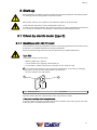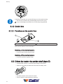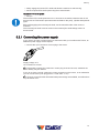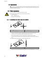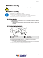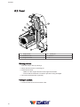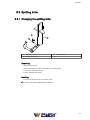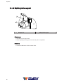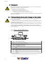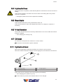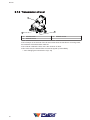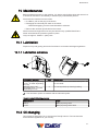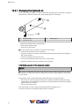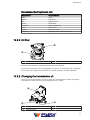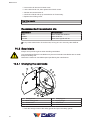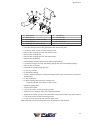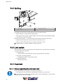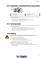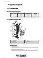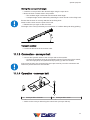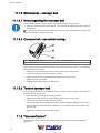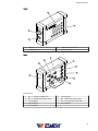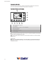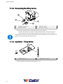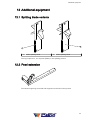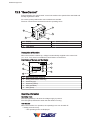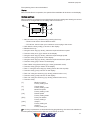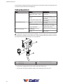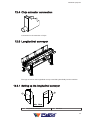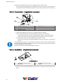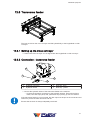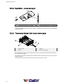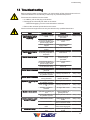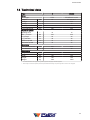
1
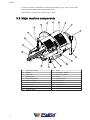
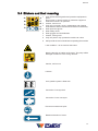
Operating Instructions
SpaltFix S-360
D1010473 - V001
*D1010473-V001*
English
Copyright by Posch Gesellschaft m.b.H., Made in Austria
Manufacturer
Manufacturer
POSCH Gesellschaft m.b.H.
Paul-Anton-Keller-Strasse 40
A-8430 Leibnitz
Tel.: +43 (0) 3452/82954
Fax: +43 (0) 3452/82954-53
E-mail: [email protected]
http://www.posch.com
© Copyright by POSCH Gesellschaft m.b.H., Made in Austria
Please be sure to fill this in before starting. Then you can be sure that this document relates
to your machine, so if you have any queries you will be given the correct information.
Machine number:..............................................................................
Serial number:.....................................................................................
POSCH Austria:
8430 Leibnitz, Paul-Anton-Keller-Strasse 40, telephone: +43 (0) 3452/82954, fax: +43 (0) 3452/82954-53, e-mail: [email protected]
POSCH Germany:
84149 Velden/Vils, Preysingallee 19, telephone: +49 (0) 8742/2081, fax: +49 (0) 8742/2083, e-mail: [email protected]
2
Contents
Contents
1
Foreword
5
1.1
Copyright notice
5
1.2
Liability for defects
5
1.3
Reservations
5
1.4
Definitions
5
1.5
Operating instructions
6
2
Safety information
7
2.1
Explanation of symbols
7
2.2
General safety information
8
2.3
Safety instructions for cut-splitters
9
2.4
Safety instructions for conveyor belts
9
2.5
Noise
10
2.6
Remaining risks
10
2.7
Proper use
10
2.8
Incorrect use
10
3
General
11
3.1
Scope
11
3.2
Description
11
3.3
Major machine components
12
3.4
Stickers and their meaning
13
4
Set-up
16
4.1
Folding down the feed
16
4.2
Conveyor belt
16
5
Start-up
17
5.1
Driven by electric motor (type E)
17
5.2
Driven by tractor via cardan shaft (type Z)
18
6
Operation
20
6.1
Work operation
20
6.2
Feed
22
6.3
Splitting knife
23
7
Put out of operation
25
7.1
Switching off the machine
25
8
Transport
26
8.1
Transporting by three-point linkage on the tractor
26
8.2
Lifting with a crane
27
3
Contents
4
9
Checks
28
9.1
Protective guards
28
9.2
Screw fittings
28
9.3
Electrical equipment
28
9.4
Hydraulic lines
29
9.5
Saw blade
29
9.6
V-belt tension
29
9.7
Oil level
29
10
Maintenance
31
10.1
Lubrication
31
10.2
Oil changing
31
10.3
Saw blade
34
10.4
Changing the V-belt
36
10.5
Splitting
40
10.6
Limit switch
40
10.7
Feed belt
40
10.8
Cleaning
41
11
Special equipment
42
11.1
Conveyor belt
42
11.2
“VolumeControl”
44
11.3
Oil cooler
53
11.4
Lifting device
53
12
Additional equipment
55
12.1
Splitting blade variants
55
12.2
Feed extension
55
12.3
“SawControl”
56
12.4
Chip extractor connection
59
12.5
Longitudinal conveyor
59
12.6
Transverse feeder
61
13
Troubleshooting
63
13.1
Disposal
64
14
Technical data
65
15
Service
66
EC Declaration of Conformity
67
Foreword
1 Foreword
Thank you for buying our product.
This machine has been built in conformity with applicable European standards and
regulations.
These operating instructions explain how to operate the machine safely and efficiently and
how to maintain it.
Any person entrusted with the transport, installation, commissioning, operation or
maintenance of the machine must have read and understood:
▪ the operating instructions
▪ the safety instructions
▪ the safety information given in the individual chapters.
To avoid operator error and ensure problem-free operation, the operating instructions must
be available to the operating personnel at all times.
1.1 Copyright notice
All documents are protected by the law of copyright.
Documents including excerpts thereof may not be distributed or reproduced nor may their
content be communicated without express permission.
1.2 Liability for defects
Read these operating instructions through carefully before putting the machine into
operation.
We accept no liability for damage or disruptions caused by failure to observe the operating
instructions.
Claims for liability must be reported as soon as the defect is identified.
Claims are null and void for example in the following cases:
▪ improper use
▪ faulty attachments and drives not supplied with the machine
▪ failure to use original spare parts and accessories
▪ conversions or modifications, where not agreed with us in writing
We are not liable for defects of wearing parts.
1.3 Reservations
Technical data, dimensions, illustrations of the machine and safety standards are subject
to continual change and are therefore not in any circumstances binding in relation to the
supplied machine.
We accept no liability for printing and typesetting errors.
1.4 Definitions
Operator
The operator is the party which operates the machine and uses it for its intended purpose
or causes it to be operated by suitable, trained personnel.
Operating personnel
5
Foreword
The operating personnel (operators) are those entrusted by the operator to operate the
machine.
Technical personnel
Technical personnel are persons entrusted by the operator of the machine with special tasks
such as installation, set-up, maintenance and troubleshooting.
Electrician
An electrician is a person who, by virtue of his specialist training, has knowledge of electrical
systems, standards and regulations and is able to identify and prevent possible hazards.
Machine
The term machine replaces the commercial designation of the object to which these
operating instructions relate (see cover sheet).
1.5 Operating instructions
This manual is a "translation of the original operating manual"
6
Safety information
2 Safety information
2.1 Explanation of symbols
The following symbols and instructions in this manual provide warnings about possible
personal injury or property damage or give useful information about working with the
machine.
DANGER
Warning about danger zones
Instruction regarding safe working, where non-compliance entails the risk of serious or
fatal injury.
Always observe these instructions and ensure that you work with particular caution and
care.
DANGER
Warning of dangerous electrical voltage
Contact with live parts can result in immediate death.
Protective covers and enclosures marked with this sign may only be opened by qualified
electricians after the electricity supply has been turned off.
DANGER
Laser radiation - class 2 (EN 60825-1)
Risk of injury to the eyes by staring into the laser beam.
DANGER
Crushing hazard
Risk of injury through upper limbs getting trapped.
DANGER
Danger of cut injuries
Risk of injury from cuts to limbs.
NOTICE
Instruction
Symbol for proper use of the machine.
Non-observance can result in malfunctions by or damage to the machine.
7
Safety information
Noise
Symbol for an area where noise levels can exceed 85 dB(A).
Non-observance can cause hearing problems or deafness.
Further information
Symbol for further information relating to a bought-in part.
Information
Action-related information.
2.2 General safety information
The machine may only be operated by persons who are familiar with the machine’s
operation and hazards and with the user manual.
▪ It is the operator’s responsibility to provide appropriate staff training.
Persons under the influence of alcohol, drugs or pharmaceutical products that impair
responsiveness must not operate the machine or carry out maintenance work on it.
The machine may only be operated if it is in perfect working condition.
If faults occur on the machine, work must be stopped immediately.
Ensure the machine is stable before starting it.
Minimum age of operative: 18 years.
Only one person may operate the machine at a time.
Take regular breaks to ensure concentration.
Ensure that your workplace is adequately illuminated as poor lighting can significantly
increase the risk of injury.
Never work without the protective guards in place.
Only carry out repair, set-up, maintenance and cleaning work when the drive is switched off
and the tool is stationary.
▪ If the machine has a PTO drive, the universal joint shaft must be removed from the
tractor.
▪ The electric motor must be switched off and the power cable disconnected.
Never leave the machine running unattended.
Switch off the machine's drive unit before carrying out any adjustments.
Only use original - POSCH - spare parts.
Do not modify or tamper with the machine.
Work on electrical equipment must only be carried out by qualified electricians.
Never use damaged cables.
Machines with electric motors must not be used in the rain as this can lead to a malfunction
of the switch or the motor.
Never stare into the laser beam.
For further information, please consult the supplied laser sensor user guide.
8
Safety information
2.3 Safety instructions for cut-splitters
Prior to starting up the machine, the machine operator must agree the safety provisions with
the operator for wood manipulation (crane, forklift, front-end loader, etc.) and must observe
these safety provisions and the safety instructions from the wood manipulation operator.
▪ This may mean that the machine operator is required to leave the place of operation
while the wood feed is loaded, in order to comply with the necessary safety distances.
These measures must be observed irrespective of how the wood feed takes place (roller,
chain, cross or step conveyor), for both stationary and mobile use.
Do not hold the log in your hand while sawing.
Do not remove offcuts or other parts of the workpiece from the cutting area while the
machine is running.
Never reach towards the rotating saw blade with gloves.
Only use the machine outdoors.
▪ Should the machine be used indoors, however, a local extractor unit (extraction at
source) is required.
The machine must always be properly maintained and must be kept free of waste material
such as chips and sawn-off pieces of wood.
Wear goggles or a face mask while working.
Use respiratory protection to reduce the risk of inhaling harmful dust.
Wear safety shoes and close-fitting clothes when working with this device.
Only use saw blades that are designed to reduce noise.
Do not use damaged or deformed saw blades.
Minimum saw blade
diameter
890 mm
Maximum saw blade
diameter
900 mm
Bore
40 mm
Only saw blades conforming to the EN 847-1 standard may be used.
When turning off the machine, always be careful of the tool runout until the machine has
come to a standstill.
The working pressure of the hydraulic system must not exceed 230 bar.
2.4 Safety instructions for conveyor belts
Persons must keep clear of the danger zone.
It must be expected that material will be ejected at high speed to any position within this
area.
Never reach into the hopper or touch the conveyor belt when the machine is running.
Shut the drive down before removing any jammed pieces of wood.
The machine must not be started up without a conveyor belt (must be fitted) as an item of
protective equipment separating it from the splitting area (in line with EN ISO 13857-1).
Wear safety shoes and close-fitting clothes when working with this device.
Only use the machine outdoors.
9
Safety information
Wear protective gloves.
The working pressure of the hydraulic system must not exceed 230 bar.
2.5 Noise
The workplace-related, A-rated emission sound pressure level is
▪ 87 dB(A) when idling or
▪ 94 dB(A) when sawing,
measured at the operative's ear.
In the case of machines with a PTO drive, the noise level depends on the noise of the tractor.
Ear protection is therefore necessary.
The stated values are emissions values, and thus do not necessarily represent reliable
values for the work area. Although there is a correlation between emission and pollutant
levels, it is not possible to deduce reliably from that whether or not additional precautionary
measures are necessary. Factors that influence the level of pollutants present in the work
area include the individual nature of the work area, other sources of noise, e.g. the number
of machines and other work operations being carried out in the vicinity. Equally, permissible
values for a work area may vary between different countries. However, this information
should enable the user to estimate the dangers and risks more accurately.
2.6 Remaining risks
Even if all safety precautions are observed and the machine is used in accordance with the
instructions, some risks still remain:
▪ Touching of revolving parts or tools.
▪ Injury caused by flying logs or log pieces.
▪ Risk of burns if the engine is not properly ventilated.
▪ Hearing loss if ear protection is not worn when working.
▪ Human error (e.g. due to excessive physical exertion, mental strain, etc.)
With every machine, some risks still remain. Therefore you should always be very careful
when working. It is up to the operating personnel to ensure that work is carried out safely.
2.7 Proper use
The SpaltFix S-360 is a cutting and splitting machine for logs with a diameter of 7 - 35 cm.
Using pre-split firewood can lead to a lower level of firewood quality and decreased
performance of the machine.
The machine splits logs with a splitting force of 12 t into 2, 4, 6 or 8 sections. The section
length is adjustable from 20 - 50 cm.
The machine may only be used to process firewood.
2.8 Incorrect use
Any incorrect use or use other than that specified under "Proper use" is expressly forbidden.
10
General
3 General
3.1 Scope
This user manual applies to the following machines:
Machine type
Article no. *
M3857
M3877
Designation - Type
SpaltFix S-360 - Z
SpaltFix S-360 - ZE22D
Drive
PTO
PTO/Electric motor
*....The article number is stamped on the machine's rating plate.
Models
Special equipment
.....C
With oil cooler
.....F15
Conveyor belt 1.5 m, hydraulic drive
.....KF4
4 m sliding conveyor belt, hydraulic drive
.....KF5
5 m sliding conveyor belt, hydraulic drive
SO577
VolumeControl
Additional equipment
F0003458
Feed extension
F0002952
Chips - 100 mm extractor connection
F0001898
Tank heating
F0003485
SawControl
F0001826
6-billet splitting blade
F0001832
8-billet splitting blade
F0002955
Lighting unit
F0002251
Hour counter for machines with PTO drive
F0002942
Timber support block with lifting device
Longitudinal
conveyors
are available in lengths of 2, 3 and 4 m
Cross conveyors are available in lengths of 2.2 / 3.2 and 4.2 m - with 2 to 4 chain strands
3.2 Description
The SpaltFix S-360 machine is a firewood processing machine which is used to cut and
then split firewood.
The log is cut in a horizontal position and is held in place with the claw while being cut.
The log is then cut to length by the hydraulically advanced saw blade.
Once the log has been sawn through, it drops into the splitting trough.
The ram of the hydraulic splitter advances and presses the log against the splitting knife.
The hydraulically height-adjustable splitting knife allows the optimum setting to be achieved
in any operating situation.
11
General
A choice of options is available for discharging the split logs, e.g. via a conveyor belt.
The cutting and splitting tool is hydraulically driven.
The machine is driven by an electric motor or a pto.
3.3 Major machine components
4
5
3
2
6
1
7
19
8
9
10
11
18
17
16
15
12
13
1
2
3
4
5
6
7
8
9
10
12
Hold-down device
Splitter
Saw unit
Rating plate
Rear safety guard
Cover - V-belt
Drive – PTO shaft
Switch/plug
Three-point linkage
Electric motor
14
11
12
13
14
15
16
17
18
19
Feed
Operation - splitter
Front guard plate
Frame
Hydraulic tank
Control box
Operation
Safety guard
Splitting blade
General
Z2001156
3.4 Stickers and their meaning
1
9
1
8
2
7
3
6
4
5
2
3
4
5
6
7
8
9
Only operate with all guards and protective equipment in
place
Do not open or remove guards or protective equipment
while the machine is in operation
Caution, tool runs on
Only carry out repair, set-up, maintenance and cleaning
work when the drive is switched off and the tool is stationary.
Wear protective gloves
Wear safety shoes
Wear goggles and ear defenders
Caution, moving tools
Only one person may operate the machine at a time
Always read the user manual before operating the machine
Laser radiation – do not look into the beam!
Note the direction of rotation of the motor. The pump will be
damaged if rotation is in the wrong direction.
Z2001170
Caution, tool runs on
Z2001320
Lift here
Z2001084
Our hydraulic system is filled with:
Z2001149
Connection: Conveyor belt
Z2001199
Connection: Cross conveyors
Z2001201
Pressure measurement point
bar
Z2001214
Rotational direction of motor
Z2001220
13
General
Rotational direction of PTO
Z2001220
Rotational direction of saw blade
Z2001220
PTO speed
Lifting point for forklift
Z2001311
Oil level
Z2001360
Maximum saw blade diameter
max 900 mm
min 890 mm
40 mm
Z2001394
Lubrication point
Z2050400
Stickers on controls
Stop
4
1
2
5
7
3
6
1
2
3
4
5
6
7
Feed (forwards)
Feed (backwards)
Saw
Split
Splitting knife (up / down)
Cross conveyor (forwards / backwards)
Conveyor belt (forwards / backwards)
Z2001405
Split
Z2040020
14
General
Stickers on belt conveyor
Danger zone
5
m
Z2001162
Maximum angle (on conveyor belt)
max.
35˚
Z2001206
Lubrication point
Z2050400
Stickers on longitudinal conveyor
Danger zone
5
m
Z2001162
Caution, moving tools
Lubrication point
Z2050400
Stickers on the cross-conveyor
Danger zone
Z2001204
5
m
Z2001162
Maximum weight load
max.
1,5 t
1m
Lubrication point
Z2050400
15
Set-up
4 Set-up
Ensure the machine is stable before starting it.
Set up the machine on a level, firm and clear work surface.
The machine must be placed directly on the ground. Do not place wooden boards, flat pieces
of metal etc. underneath it.
The machine must not be set up under an overhead electrical power line.
4.1 Folding down the feed
See ..... Feed [➙ 22]
4.2 Conveyor belt
▪ Move the conveyer belt to the working position.
See ..... Conveyor belt [➙ 42]
16
Start-up
5 Start-up
Before starting to operate the machine, please check that the protective and safety systems
are working and also the hydraulic hoses and oil level.
Before each start-up, the condition of the electrical cables must be checked.
Check that the saw blade is firmly seated before each use.
If a fault occurs during operation, the machine must be shut down immediately and secured
so it cannot be switched on accidentally or started-up by unauthorised persons.
5.1 Driven by electric motor (type E)
5.1.1 Machines with 400 V motor
The machine must only be operated on electric circuits equipped with 30 mA FI fault current
protection or a Portable Residual Current Device (PRCD).
Work on electrical equipment must only be carried out by qualified electricians.
Type E22
Connect the machine to the mains:
▪ Mains voltage 400 V (50 Hz)
▪ Circuit-breaker 32 A (tripping characteristic C)
▪ For the feed, a cable cross-section of at least 10 mm² must be used.
This cable cross-section is only a minimum specification. In the event of a lengthy
supply cable, its size must be determined by an electrician.
▪ Turn the switch to the ON position.
1
2
1
Neutral position
2
On position
Note the rotation direction of the electric motor (see arrow on motor).
If the motor is rotating in the wrong direction:
A phase inverter in the plug controls the direction of rotation of the motor (press in the disc
in the plug with a screwdriver and turn 180˚).
17
Start-up
A tight plug connection can rip the CEE plug out of the switch housing.
▪ This can be remedied using standard plugs and a silicone spray.
Any such damage to the switch is not covered by the guarantee.
5.1.2 Control box
5.1.2.1 Functions on the control box
1
2
1
Button (green) – Start system
2
Button (red) – Stop system
There are two buttons on the control box.
Switching on the electrical system:
▪ Press the green button (System start).
Switching off the electrical system:
▪ Press the red button (System stop).
5.2 Driven by tractor via cardan shaft (type Z)
▪ Assemble the machine on the three-point linkage of the tractor.
▪ Attach the universal joint shaft and secure with the safety chain.
▪ Clockwise rotation of the tractor PTO shaft.
▪ Turn the tractor's manual throttle to minimum.
18
Start-up
▪ Slowly engage the tractor PTO shaft and allow the machine to start moving.
▪ Set the required PTO shaft speed using the manual throttle.
Maximum PTO shaft speed:
▪ 480 rpm
The maximum PTO shaft speed must on no account be exceeded, otherwise the oil will
become too hot. This leads to premature wear and leaks in the pump, cylinder and hydraulic
pipes.
Before disengaging the universal joint shaft, set the manual throttle of the tractor to
minimum.
The universal joint shaft must be stored in the universal joint shaft linkage when it is
disconnected.
5.2.1 Connecting the power supply
If you use an oil cooler, VolumeControl or SawControl with your machine with Z-drive, an
additional power supply will be required.
▪ Connect the 3-pin continuous current plug to the tractor.
Supply voltage 12 V
16 A Continuous current
Remember to unplug the continuous current plug at the end of work, otherwise the
tractor battery may be drained.
If you do not have a 3-pole continuous current connection on the tractor, as an alternative
you can connect the 7-pole plug (brown + to 58L blue - to 31).
However, ensure that the aforementioned power ratings are available, as malfunctions
may otherwise occur.
19
Operation
6 Operation
At outdoor temperatures below 0°C, let the machine idle for approximately five minutes
to allow the hydraulic system to reach the correct operating temperature (the hydraulic pipes
will then be warm to the touch).
6.1 Work operation
Only one person may operate the machine at a time.
Ensure that no other people are in the vicinity of the machine.
▪ Start the machine.
See ..... Start-up [➙ 17]
▪ Place the wood on the feed.
6.1.1 Operating the feed, saw and splitter
1
4
2
3
1
2
Split
Feed - backwards
3
4
Saw
Feed - forwards
▪ Using the control lever (Infeed - advance) move the log as far as the log stop.
▪ Pull the control lever (sawing) forwards and saw through the wood.
▪ Hold the lever towards you until the log has been completely sawn through.
▪ Use the control lever (Split) to start a splitting stroke (push the lever briefly away from
you).
The splitting knife can be adjusted (to set the split centre point).
1
2
1
Splitting blade – up
2
Splitting blade - down
▪ Adjust the centre of the splitting knife using the control lever (Splitting knife – up / down).
20
Operation
6.1.1.1 Notes on sawing
The drive must always be switched off before clearing a blockage.
6.1.1.2 Notes on splitting
Only use logs up to a diameter of 7 - 35 cm.
Logs must be pushed longitudinally towards the splitting blade.
▪ If necessary, correct the positioning and only then start the splitting process.
Remove jammed wood from the splitting blade with a striking tool.
6.1.2 Stop function
▪ If the safety guards are opened during work, the splitter will stop and the saw will return
to its home position.
– After closing the safety guards the splitting process will continue from where it was
interrupted.
6.1.3 Adjusting the log length
2
4
3
1
1
2
Fastening screw
Stop
3
4
Stop support
Threaded hole
The log length can be adjusted to 20, 25, 30, 33, 40, 45 or 50 cm using the stop.
1. Undo the fastening screw and remove the stop.
– On the stop support there are threaded holes for adjusting the cut length required.
2. Select the desired length and retighten the fastening screws.
21
Operation
6.2 Feed
5
1
4
2
3
1
2
3
Snap-in lock
Stabiliser foot
Support holder
4
5
Cotter pin
Feed
Working position:
▪ Open the snap-in lock by turning it.
▪ Unlock and remove the connecting pin.
▪ Fold down the feed.
– Make sure the support foot fits in the support foot holder.
– Ensure that the feed belt is centred to prevent it being damaged.
▪ Pull out the feed extension (optional).
Transport position:
▪ Proceed as above but in the reverse order.
22
Operation
6.3 Splitting knife
6.3.1 Changing the splitting knife
1
3
2
1
2
Clip pin
Splitting knife pin
3
Splitting knife
Removing:
▪ Remove the clip pin.
▪ Support the splitting knife to prevent it from falling down.
▪ Pull out the splitting knife pin.
▪ Lift the splitting knife clear.
Installing:
▪ Proceed as above but in the reverse order.
Grease the splitting blade before refitting it.
23
Operation
6.3.2 Splitting knife support
1
2
1
Hexagon bolt
2
Splitting knife support
Removing:
▪ Undo the four hexagon bolts.
▪ Tilt the splitting knife support forwards and pull it out upwards.
Installing:
▪ Proceed as above but in the reverse order.
24
Put out of operation
7 Put out of operation
Before switching off the machine, depressurise all hydraulic functions
by placing all control levers in the neutral position.
7.1 Switching off the machine
Driven by electric motor (Type E)
Type E22
▪ Move the switch to the 0 position.
Driven by tractor via universal joint shaft (type PZG)
▪ Disengage the universal joint shaft on the tractor.
– Before disengaging, turn the manual throttle to minimum.
25
Transport
8 Transport
Before transport, it is vital to switch off the drive and secure it so it cannot be switched on
accidentally or started-up by unauthorised persons.
Disconnect the machine from the mains.
▪ In addition, pull out the plug of the device.
▪ Disengage the universal joint shaft on the tractor.
– Before disengaging, turn the manual throttle to minimum.
When turning off the machine, always be careful of the saw blade runout until the machine
has come to a standstill.
8.1 Transporting by three-point linkage on the tractor
No one is permitted to stand in the area between the tractor and the machine during the
raising or lowering process.
▪ Attach the machine to the three-point linkage and use the tractor hydraulics to raise it.
If the tractor's rear lights are obscured, a light must be fitted to the rear of the machine (e.g.
magnetic holder, clip-on light, etc.)
Due to the weight of the machine, the tractor-machine combination can become unstable.
In order to test the overall stability, the following formula can be used to calculate the
minimum weight on the front side IF,min with a minimum front axle load of 20% of the empty
weight of the tractor:
I F,min =
(I R x ( c
+ d )) - ( TF x b ) +( 0,2 x TE x b )
a + b
TE
IF
TF
TR
IR
TE
(kg)
Empty weight of the tractor
*
TF
(kg)
Front axle load of the empty tractor
*
TR
(kg)
Rear axle load of the empty tractor
*
IR
(kg)
Total weight of the machine
**
IF
(kg)
Total weight of the front load
a
(m)
b
c
(m)
(m)
d
(m)
Distance between front load's centre of gravity and centre of the front
axle
Wheelbase of the tractor
Distance between centre of the rear axle and centre of the lower link
balls
Distance between centre of the lower link balls and the machine's centre
of gravity
*….. see tractor operating instructions
**….. see "Technical Data" (It is vital to ensure that the weight of any additional equipment on the machine is taken into account)
***….. take measurement
26
***
***
***
***
Transport
Observe the road traffic regulations when driving on public highways.
Maximum transport speed: 25 km/h
When the machine is uncoupled from the tractor, it must be placed on a firm, level
surface.
8.2 Lifting with a crane
1
2
2
2
1
Lifting gear
2
Lifting eye
When using a crane, only lift the machine by the lifting eyes.
Only lifting gear with the permitted load capacity may be used.
27
Checks
9 Checks
Before control work on the machine, it is vital to switch off the drive and secure it so it cannot
be switched on accidentally or started-up by unauthorised persons.
Disconnect the machine from the mains.
▪ In addition, pull out the plug of the device.
▪ Disengage the universal joint shaft on the tractor.
– Before disengaging, turn the manual throttle to minimum.
▪ Remove the universal joint shaft from the tractor.
When turning off the machine, always be careful of the saw blade runout until the machine
has come to a standstill.
9.1 Protective guards
All the protective guards (covers, safety grilles, etc.) must be in place on the machine at all
times!
9.2 Screw fittings
Tighten all screws and nuts after the first hour of operation.
Tighten the screws and nuts after every 100 hours of operation.
▪ Replace missing screws and nuts.
9.3 Electrical equipment
Before each start-up, the condition of the electrical cables must be checked.
▪ Damaged cables must be replaced immediately.
A regular test of the electrical equipment should be carried out by an electrical specialist in
line with the statutory requirements, but at least every three years, with the test results being
recorded. As a minimum, the test should cover the following points:
▪ Visual inspection of correct condition
▪ Protective measures to prevent direct contact (basic protection)
▪ Protective measures to prevent indirect contact (fault protection)
▪ Where appropriate, protective measures providing additional protection
▪ Where appropriate, recording of the temperature of relevant electrical operating
resources.
In the case of moveable electrical operating resources, the tests must cover the following,
as a minimum:
▪ Visual inspection of correct condition
▪ Function test
▪ Where appropriate, test of the earth conductor and measurement of the earth conductor
current
▪ Where appropriate, measurement of the insulation resistance.
Work on electrical equipment must only be carried out by qualified electricians.
28
Checks
9.4 Hydraulic lines
After the first hour of operation, check that all hydraulic connections are secure and are not
leaking.
Check that all hydraulic connections are secure and are not leaking after every further
100 hours of operation.
▪ Damaged hydraulic lines must be replaced immediately.
9.5 Saw blade
Check that the saw blade is firmly seated before each use.
Check the saw blade for wear and damage before each use. Sharpen or replace it if
necessary.
9.6 V-belt tension
The V-belts must be tensioned so that they deflect about 8 mm in the middle when thumb
pressure is applied.
▪ See: Changing the V-belt [➙ 36]
9.7 Oil level
To check the oil level place the machine on an even surface.
Check the oil level with the pusher retracted.
9.7.1 Hydraulic oil level
When the oil sight glass is filled above halfway, the oil level is at its maximum.
When the oil level is towards the bottom of the oil sight glass, the oil level its at its minimum.
1
3
2
1
2
Oil inlet screw
Oil drain screw
3
Oil sight glass
If this is the case, the hydraulic oil must be topped up immediately.
▪ See: Changing the hydraulic oil [➙ 32]
The oil filter only needs to be checked when the oil is changed.
29
Checks
9.7.2 Transmission oil level
1
3
2
1
2
Oil inlet screw
Oil level screw
3
Oil drain screw
If the oil seeps out of the hole of the oil level screw when the machine is on level ground,
the maximum oil level has been reached.
If the oil level is below the hole, this is the minimum oil level.
If this is the case, the transmission oil must be topped up immediately.
▪ See: Changing the transmission oil [➙ 33]
30
Maintenance
10 Maintenance
Before maintenance work on the machine, it is vital to switch off the drive and secure it so
it cannot be switched on accidentally or started-up by unauthorised persons.
Disconnect the machine from the mains.
▪ In addition, pull out the plug of the device.
▪ Disengage the universal joint shaft on the tractor.
– Before disengaging, turn the manual throttle to minimum.
▪ Remove the universal joint shaft from the tractor.
Work on electrical equipment must only be carried out by qualified electricians.
Never work without the protective guards in place.
Only use original - POSCH - spare parts.
10.1 Lubrication
Dispose of oily and greasy parts and oil residues in accordance with legal regulations.
10.1.1 Lubrication schedule
1
Lubrication intervals
Weekly (every 40 operating
hours - or fewer depending
on use)
Monthly (every 160
operating hours - or fewer
depending on use)
2
Item
1
2
What/where
On the back of the central lubrication point - for
the saw shaft
On conveyor belt, top housing bearing
The lubrication points are marked with the lubricate symbol.
Recommended lubricating greases:
Manufacturer
Genol
Fuchs
Type
Multi-purpose grease
Multi-purpose grease 5028
10.2 Oil changing
Old oil must be disposed of in an environment-friendly manner. Find out about the
environmental regulations in your country.
31
Maintenance
10.2.1 Changing the hydraulic oil
The first oil change should be carried out after 500 operating hours, all further oil changes
should then be carried out after every 1000 operating hours or annually.
1
3
2
1
2
Oil inlet screw
Oil drain screw
3
Oil sight glass
▪ Retract the pusher before changing the oil.
▪ Remove the oil filling screw.
▪ Open the oil drain screw.
The oil drain screw is located on the base of the oil tank.
▪ Drain the old hydraulic oil into a container.
▪ Screw the oil drain screw back into the tank and fill with new hydraulic oil through the
filler screw opening.
▪ Screw the oil filling screw into the tank.
▪ Turn on the machine and allow it to run for a short while.
▪ Check the oil level and top up hydraulic oil if necessary.
Total filling capacity of the hydraulic system:
Quantity
60 litre
Please note that the information here concerns initial oil filling. Depending on the type
and variant, the refill quantity may be slightly less (as some of the hydraulic components
are not empty).
Our hydraulic system is filled with high-quality OMV ATF II transmission fluid.
▪ This oil has an extremely high viscosity index, exhibits excellent foaming and aging
characteristics and excellent flow properties at low temperatures and protects reliably
against wear and corrosion.
▪ Viscosity class ISO VG 46.
This high-quality oil comes highly recommended when changing the oil.
A mixture of products of the same quality poses no problem.
32
Maintenance
Recommended hydraulic oils
Manufacturer
OMV
SHELL
ELF
ESSO
CASTROL
ARAL
GENOL
FUCHS
Oil specification
ATF II
Donax TA
Hydrelf DS 46
Univis N46
Hyspin AWH-M 46
Vitam VF46
Hydraulic oil 520
Plantohyd 32S * / Renolin B46 HVI
*.....biological hydraulic oils
10.2.2 Oil filter
1
2
1
Filter cover
2
Filter insert
The filter insert should be changed every time the oil is changed.
Any aluminium particles can be disregarded, as these occur when the pump is running in.
Do not wash out the filter insert with petrol or paraffin products, as these damage it.
10.2.3 Changing the transmission oil
The first oil change should be carried out after 100 operating hours, further oil changes
should then be carried out every 500 operating hours or yearly.
1
3
2
1
2
Oil inlet screw
Oil level screw
3
Oil drain screw
33
Maintenance
▪ Unscrew the oil inlet and oil drain screw.
▪ Let the old oil drain out, then replace the oil drain screw.
▪ Add the new transmission oil.
▪ Check the oil level and top up transmission oil if necessary.
▪ Replace the oil filling screw.
Total filling capacity
0.8 litres
Recommended transmission oils
Manufacturer
OMV
GENOL
FUCHS
Oil specification
Gear Oil MP SAE 85W-90
Gear oil MP 90
Titan Gear Hypoid SAE 90
Any other transmission oil can be used, so long as it is in viscosity class SAE 90.
10.3 Saw blade
Always wear protective gloves when handling saw blades.
Only strengthened POSCH saw blades may be used. Standard saw blades are too weak
and pose a safety risk.
Observe the maximum saw blade speed specified by the manufacturer.
10.3.1 Changing the saw blade
3
1
7
5
2
6
8
4
1
2
3
4
Hexagon bolt
Rear safety guard
Wood insert
Circular saw wrench
5
6
7
8
Clamping nut
Spring flange
Saw blade
Limit switch
▪ Undo the hexagon bolts of the safety guards and open the safety guards.
34
Maintenance
▪ Hold the circular saw shaft with the spring flange wrench and undo the clamping nut
with the circular saw wrench.
▪ Remove the spring flange and the saw blade.
▪ Put the new blade in and secure it.
The clamping nut must be screwed back on as it was before.
Position the saw blade in such a way that the saw blade teeth are pointing in the
direction of rotation (see arrow).
▪ Fasten the wood insert about 2 mm away from the saw blade.
▪ Close the safety guards and secure them again.
Ensure that all chips are removed from around the limit switch.
The tongue of the limit switch must slip easily into the limit switch when closing.
Recommended saw blade
Item no.
Z1300130
Diameter
900 mm
Hole
40 mm
Teeth
96
Type
Carbide (widia)
Only saw blades conforming to the EN 847-1 standard may be used.
Safety of the saw blade
In accordance with the EN 1870-6 standard, the saw blade is secured with Aluminium
inserts.
These are subject to wear and should be replaced as soon as they are worn out.
10.3.2 Sharpening the saw blade
Saw blades should only be resharpened by a specialist company.
Carbide saw blade
Usage tips for carbide saw blades
Carbide tipped circular saw blades have a long service life. These blades are high precision
machine tools, so must always be correctly handled and used.
▪ The hardness of the carbide tips means they must be protected from nicks.
– Incorrect storage can result in damage to the tips of the teeth. Place the circular saw
blade on foam rubber or a similar surface.
– Do not attempt to cut any nails, metal brackets or anything similar that may be in
the wood.
– The circular saw blade must not be subjected to any impacts or knocks.
▪ Before starting up the motor, check the free-running of the circular saw blade and ensure
that the direction of rotation is correct.
▪ Running down circular saw blades must not be slowed by external means.
▪ Feed slowly and continuously, avoid any jerky cutting movements.
▪ Clean the circular saw blade regularly with a resin removing agent.
▪ In no-load operation the carbide circular saw blade generates less noise. When cutting
the noise level depends on the type of wood being cut.
Incorrect use will invalidate any warranty claims. Resin-coated blades are excluded
from the warranty exchange service.
35
Maintenance
10.4 Changing the V-belt
10.4.1 Tips on changing the V-belt
If one V-belt is being changed, then all V-belts must be changed!
The V-belts must be fitted loose. If they are "forced" onto the V-belt pulley, they may be
damaged and quickly tear.
The V-belts must be tensioned so that they deflect about 8 mm in the middle when
thumb pressure is applied.
V-belt types
Machine type
Z
ZE22D
Belt
XPA 1285 Lw
XPA 1285 Lw
Number (pcs.)
4
4
10.4.2 Changing the V-belts on PTO drives
3
2
1
1
2
Lock nut
Tensioning screw
3
Tension spring
▪ Loosen the lock nuts on both tensioning screws.
▪ Remove both tension springs from the saw feed completely.
36
Item no.
Z1940086
Z1940086
Maintenance
1
2
4
5
6
3
1
2
3
Cover - V-belt
PTO shaft cover
Hexagon bolt - adjustment plate
4
5
6
Adjustment plate
Lock nut - tensioning screw
Tensioning screw
▪ Remove the cover for the V-belt and the PTO shaft cover.
▪ Undo the four hexagon bolts of the adjustment plate.
▪ Undo the lock nuts of both tensioning screws, so that the adjustment plate is lowered.
1
2
1
Shaft guard
2
V-belt
▪ Remove the shaft guard.
▪ Remove the old V-belts.
▪ Unthread the V-belt through the hole.
▪ Fit the new V-belts.
▪ Fit the shaft guard.
▪ Tension the V-belts.
▪ Lock the lock nuts on both tensioning screws.
▪ Tighten the four hexagon bolts of the adjustment plate.
▪ Tighten both tension springs on the saw feed, as they were before they were undone.
▪ Lock the lock nuts on both tensioning screws.
▪ Fit the cover for the V-belt and the PTO shaft cover.
Before operating, all protective guards must be attached to the machine.
37
Maintenance
10.4.3 Changing the V-belts on PTO/electric drives
3
2
1
1
2
Lock nut
Tensioning screw
3
Tension spring
▪ Loosen the lock nuts on both tensioning screws.
▪ Remove both tension springs from the saw feed completely.
1
2
4
5
6
3
1
2
3
Cover - V-belt
PTO shaft cover
Hexagon bolt - adjustment plate
4
5
6
Adjustment plate
Lock nut - tensioning screw
Tensioning screw
▪ Remove the cover for the V-belt and the PTO shaft cover.
▪ Undo the four hexagon bolts of the adjustment plate.
▪ Undo the lock nuts of both tensioning screws, so that the adjustment plate is lowered.
38
Maintenance
7
6
9
1
5
4
3
8
2
1
2
3
4
5
Guard plate
Allen screw
Coupling part – electric motor
Coupling hub
Coupling part - transmission
6
7
8
9
Parallel key
Threaded pin
Hexagon nut
Bearing flange
▪ Undo the hexagon bolts of the guard plate and remove the plate.
▪ Loosen the Allen screws from the coupling parts.
▪ Remove the coupling part from the electric motor.
▪ Remove the coupling hub.
▪ Remove the coupling part from the transmission.
▪ Remove the parallel key.
▪ Unscrew both threaded pins from the plate flange bearing.
▪ Loosen the hexagon nut from the bearing flange and pull out the bearing flange.
▪ Remove the old V-belts.
▪ Unthread the V-belt through the hole.
▪ Fit the new V-belts.
▪ Fit the bearing flange.
▪ Screw in both threaded pins of the plate flange bearing and secure them (Loctite 242
threadlocker).
▪ Fit the parallel key.
▪ Fit both coupling parts using the coupling hub.
– Tightening torque of the Allen screws: 70 Nm
▪ Attach the guard plate.
▪ Tension the V-belts.
▪ Lock the lock nuts on both tensioning screws.
▪ Tighten the four hexagon bolts of the adjustment plate.
▪ Tighten both tension springs on the saw feed, as they were before they were undone.
▪ Lock the lock nuts on both tensioning screws.
▪ Fit the cover for the V-belt and the PTO shaft cover.
Before operating, all protective guards must be attached to the machine.
39
Maintenance
10.5 Splitting
1
1
2
3
1
2
Lock nut
Shut-off rod
3
Valve shut-off rod
If the splitter pusher does not automatically retract, proceed as follows:
▪ Remove the front control panel and guard plate.
▪ Undo the lock nuts and turn inwards slightly - the shut-off rod will be shortened slightly.
▪ Lock the nuts in this new position.
Ensure a play of approx. 1 - 2 mm between the nuts and the valve shut-off rod (3).
▪ Switch on the machine and carry out a work cycle with no wood.
▪ Switch on the machine and carry out a work cycle with no wood.
Repeat points 1-4 until the splitter is working correctly.
10.6 Limit switch
If the motor will not start on machines with a PTO/electric drive, the limit switch may be dirty,
incorrectly adjusted or defective.
▪ Limit switch dirty.
– Clean all dirt form the limit switch (using compressed air if necessary).
▪ Limit switch incorrectly adjusted:
– Readjust limit switch or limit switch tongue.
▪ Limit switch defective:
– Replace limit switch.
10.7 Feed belt
10.7.1 Notes regarding the conveyor belt
Check that the belt runs centrally. It must not run off centre.
▪ If this happens, centre the belt by adjusting the drive pulley or return drum.
From time to time remove the material that drops down underneath the conveyor belt,
otherwise the belt may be damaged.
40
Maintenance
10.7.2 Conveyor belt - ensuring the machine is running centrally
1
2
3
4
1
2
Conveyor belt
Return drum
3
4
Tensioning screw
Lock nut
If the conveyor belt is not running centrally on the drive and/or return drum, it is possible to
adjust the direction of travel.
▪ Loosen the lock nuts on both tensioning screws.
▪ Align the return drum by tightening both tensioning screws evenly.
▪ Lock the lock nuts on both tensioning screws.
10.7.3 Tensioning the belt
The conveyor belt may become slack over time as a result of wear and tear. If this happens,
the belt must be retensioned.
▪ Loosen the lock nuts on both tensioning screws.
▪ Tension the conveyor belt by tightening both tensioning screws evenly.
▪ Tension the conveyor belt sufficiently (underside of belt must not sag).
▪ Lock the lock nuts on both tensioning screws.
10.8 Cleaning
Before cleaning work on the machine, it is vital to switch off the drive and secure it so it
cannot be switched on accidentally or started-up by unauthorised persons.
Disconnect the machine from the mains.
▪ In addition, pull out the plug of the device.
▪ Disengage the universal joint shaft on the tractor.
– Before disengaging, turn the manual throttle to minimum.
▪ Remove the universal joint shaft from the tractor.
Clean the machine regularly to ensure proper operation.
Only wash new machines (during the first 3 months) with a sponge.
▪ The paint is not yet completely set, so cleaning with a high pressure cleaner may
damage the finish.
41
Special equipment
11 Special equipment
11.1 Conveyor belt
11.1.1 Conveyor belt types
Conveyor belt type
F15
KF4
KF5
Conveyor belt length
150 cm
400 cm
500 cm
Conveyor height
100 cm
250 cm
300 cm
Belt width
30 cm
30 cm
30 cm
11.1.2 Set up conveyor belt
5
3
2
4
1
1
2
3
Spring cotter
Rope winch
Securing hook
4
5
Tab
Eccentric lock
Working position:
▪ Pull out the spring pin.
▪ Gently tension the rope winch, so that the securing hook can be pulled out of the tab.
▪ Fold out the conveyor belt completely using the rope winch, until the rope becomes slack
and the conveyor belt is stretched out.
▪ Use the cam-type closure to secure the upper and lower parts of the conveyor belt.
42
Special equipment
Setting the conveyor belt angle:
▪ Crank the conveyor belt to the desired height using the rope winch.
▪ Mount the chain on both sides in this position.
– The smallest angle is achieved with the whole chain length.
– A steeper angle can be achieved by attaching the chain shorter on the fixing hook.
Ensure that the chain is correctly attached to the fixing hook.
Never hook the chain onto the point of the hook.
▪ Release the rope again so that it is slack.
The angle of the conveyor belt may not exceed 35° or it will be destroyed during splitting.
max. 35˚
Transport position:
▪ Proceed as above but in the reverse order.
11.1.3 Connection - conveyor belt
▪ Connect the hydraulic hoses of the conveyor belt to the machine.
– Connect the hydraulic hoses to the hydraulic sleeves. Ensure that colours match;
blue dust caps (flow) and yellow dust caps (return) go with one another.
If the conveyor belt is not connected, the dust caps must be put on the connectors and
sleeves to protect them from dust and dirt.
11.1.4 Operation - conveyor belt
1
2
1
Conveyor belt - forwards
2
Conveyor belt - return
▪ Switch on the conveyor belt using the control lever (conveyor belt on).
43
Special equipment
11.1.5 Maintenance - conveyor belt
11.1.5.1 Notes regarding the conveyor belt
Check that the belt is running centrally. The belt drive dogs must not move.
▪ If they do, the belt must be corrected so it runs centrally by adjusting the drive pulley or
return drum.
From time to time remove the material that drops down underneath the conveyor belt
to prevent damage to the belt drive dogs.
11.1.5.2 Conveyor belt - set central running
1
2
3
1
2
Fastening screw
Lock nut
3
Tensioning screw
If the conveyor belt is not running centrally on the drive and/or tail pulleys, it is possible to
adjust the direction of travel.
▪ Slightly loosen the fastening screws on each side of the conveyor belt.
▪ Loosen the lock nuts on both tensioning screws.
▪ Align the return drum by tightening both tensioning screws evenly.
▪ Tighten the lock nuts again.
▪ Tighten the fastening screws on both sides.
11.1.5.3 Tension conveyor belt
The conveyor belt may become slack over time as a result of wear and tear. If this happens,
the belt must be retensioned.
▪ Move the conveyer belt to the working position.
▪ Slightly loosen the fastening screws on each side of the conveyor belt.
▪ Loosen the lock nuts on both tensioning screws.
▪ Tension the upper part of the conveyor belt by tightening both tensioning screws evenly.
▪ After the belt has been tensioned sufficiently, lock the tensioning screws again using
the lock nuts.
▪ Tighten the fastening screws on both sides.
11.2 “VolumeControl”
The “VolumeControl” control unit is used to detect the volume of wood that has been
processed.
44
Special equipment
Front:
1
2
3
4
1
2
Display
Control buttons
3
4
USB socket with cover
Update button
Rear:
8
7
4
6
3
2
9
1
5
Connections:
1
2
3
4
5
No. 1 – Supply voltage SS1
No. 2 – Rope hoist sensor SS8
not assigned
not assigned
not assigned
6
7
8
9
not assigned
No. 7 Pressure sensor SS6
No. 8 Log diameter laser SS7
not assigned
45
Special equipment
Description of function
When the machine is started up, voltage is automatically supplied to the control unit
(10 - 30 V - DC), there is no additional On/Off button on the device.
Significance of the keys and the display:
1
7
Esc
6
5
A
2
1
2
3
4
5
6
7
F1
F2
F3
F4
3
3
3
3
4
Basic display after switch-on
not assigned
Function keys F1 – F2 (F3 – F4 not assigned)
Enter key (confirm)
Arrow key (down)
Escape key (cancel/exit)
Arrow key (up)
F1 - Switch between daily and total volume counter “m³ FIXED COUNTER” (reset the daily
volume counter by holding down the key)
F2 - Switch between daily and total hour counter (reset the daily hour counter by holding
down the key)
General note:
With second splitting operations, care must be taken to ensure that the wood is not
positioned below the laser beam again, as an excessively large volume of wood will be
calculated otherwise.
46
Special equipment
User settings
In principle, the values are set to an optimum level and should not be changed.
However, the user can change some settings if necessary.
▪ Using the arrow key [down], navigate to the [EIN1] field (15) and select [Client Menu]
with the [Enter key].
15
▪ Using the arrow key [up / down], select the desired adjustment.
▪ Press the [Enter key] and change the value using the arrow key [up/down].
▪ Confirm the new value with the [Enter key].
16
[Load relieving:]
[Tolerance pressure:]
[Log deviation:]
[Volume no ø-value:]
[Splitter release:]
[Language:]
[Display:]
[Contrast:]
[Log file:]
[Flash Disk ready]
[V2.00]
not assigned
Difference in pressure when length measurement is activated.
Factory setting: 5 bar
not assigned
If no log section is found under the log diameter laser sensor when
triggering the splitting process (wood too short, transverse, etc.),
a selection can be made as to whether the last log diameter is
included in the volume calculation (ON) or not (OFF).
Factory setting: ON
not assigned
Menu language (German, English, French)
Factory setting: German
Light/dark - mode
Factory setting: Day
Display contrast
Factory setting: 22
Creating a record → see Creating a log file
Factory setting: OFF
USB stick connected and ready
Version number
47
Special equipment
▪ Using the arrow key [up], return to the [START] field (16) and return to the start menu
using the [Enter key].
Creating a log file:
▪ Open the USB socket cover at the side of the housing.
▪ Connect the USB stick (FAT32 compatible) to the USB port.
▪ Navigate to the [Client menu] (see "User settings" for description).
▪ Using the arrow key [up], navigate to the [Log file: / OFF] field and press the [Enter key].
▪ Using the arrow key [up / down], set the value to [ON].
▪ Press the [Enter key].
▪ Using the arrow key [up], navigate to the [NEW] field and press the [Enter key] → The
log file will be saved, increasing the number of log files by 1.
– Each time the [Enter key] is pressed, the number of log files will increase by 1, which
makes it possible to create a new log file for each volume unit (packing unit).
Wait approximately another 15 secs after the last splitting process.
▪ Using the arrow key [up], return to the [START] field and return to the start menu using
the [Enter key].
▪ Disconnect the USB stick at the side of the housing.
▪ Close the cover of the USB socket again.
48
Special equipment
Operating information
This is where the operating conditions of the machine are displayed.
▪ Using the arrow key [up / down], navigate to the [INFO] field (17) and press the [Enter
key].
17
▪ Using the arrow key [up / down], navigate to the desired row.
16
[Activation:]
[Splitting strokes:]
[Maximum pressures:]
[Occurrences ø %:]
Number of activation processes
not assigned
not assigned
Percentage of processed log diameters
▪ Using the arrow key [up], return to the [START] field (16) and return to the start menu
using the [Enter key].
Error messages
In the event of faulty wires or sensors, an error message (18) is displayed.
18
▪ Delete this message by pressing the [Enter key] or [Esc key].
– Please contact Posch Service if necessary.
Notification
“Diameter too large”
Cause
log too large
Rectification
remove log that is too large
49
Special equipment
System settings
When a machine or individual control is delivered, the basic settings are already pre-set and
should not be changed without consulting with Posch Service.
▪ Using the arrow key [up / down], navigate to the [SERV] field (19) and press the [Enter
key].
19
▪ Using the arrow key [up / down], navigate to the first digit (20) in the line [Code].
20
▪ Press the [Enter key] and enter the value 1 using the arrow key [up/down].
▪ Confirm the value 1 with the [Enter key].
▪ Using the arrow key [up / down], navigate to the second digit.
▪ Press the [Enter key] and enter the value 2 using the arrow key [up/down].
▪ Confirm the value 2 with the [Enter key].
▪ Using the arrow key [up / down], navigate to the third digit.
▪ Press the [Enter key] and enter the value 3 using the arrow key [up/down].
▪ Confirm the value 3 with the [Enter key].
▪ Using the arrow key [down], navigate to the line [OK] (21) and navigate to the system
menu with the [Enter key].
21
▪ Using the arrow key [up / down], select the desired adjustment.
▪ Press the [Enter key] and change the value using the arrow key [up/down].
▪ Confirm the new value with the [Enter key].
50
Special equipment
22
[maximum stroke:]
[Trough angle:]
[Sensor height:]
[Laser ø value)
[Calibrate]
[Function:]
[Nominal pressure:]
[Max. log length:]
[Max. log diameter:]
[Splitter S-400]
not assigned
Angle of the splitting trough
Distance of the "log diameter" laser sensor from the centre of the
splitting trough (displayed on the sensor)
See ........ Calibration function (in accordance with the table)
Displayed internal value (cannot be changed, is only displayed)
The "log diameter" laser sensor is calibrated
See ........ Calibration function (in accordance with the table)
Automatic: Knife adjustment and volume measurement
Measurement operation: volume measurement only (e.g. for
S-360)
not assigned
Maximum length of the sawn piece of wood
Maximum applicable log diameter
not assigned
Calibration function:
▪ To set the sensor height, place the supplied angle plate (a solid sheet of paper) in the
splitting trough so that the laser beam hits the centre.
2
1
1
Splitting trough
2
Laser beam
Never stare into the laser beam.
For further information, please consult the supplied laser sensor user guide.
▪ Read the value off the laser sensor and enter in the [Sensor height] field.
▪ Using the arrow key [up / down], return to the [Calibrate] field and confirm with the [Enter
key].
Using the calibration function, any possible transmission discrepancy between the laser
sensor and control is offset.
▪ Using the arrow key [up], return to the [START] field (22) and return to the start menu
using the [Enter key].
51
Special equipment
Software update
It is possible to install new operating software using a USB stick
(FAT32 compatible).
This software is provided by POSCH.
After loading the new software, all system settings and
counter values are retained.
1
2
Update procedure:
▪ Disconnect the device from the electricity supply.
– Pull out the supply plug on the rear or switch off the machine.
▪ Open the USB socket cover at the side of the housing.
▪ Connect the USB stick to the USB socket (1) and press/hold down the Update key (2).
▪ Restore the power supply.
▪ Once the display begins to flash blue, release the Update key.
– The display continues to flash for approximately 30 seconds and then glows blue
continuously → loading is complete.
▪ Disconnect the device from the electricity supply and remove the USB stick.
▪ Close the cover of the USB socket again.
▪ Restore the power supply.
– The update procedure is complete and the new software has been loaded.
Pressing the Update key at another time or in another operating mode does not have
any effect.
External voltage
If work is to be carried out on the machine with an external voltage source (e.g. welding
equipment, external start-up aid in the case of a combustion motor, etc.), it is vital that the
voltage supply to control is interrupted.
▪ Remove the plug for the voltage supply at the rear.
52
Special equipment
11.3 Oil cooler
2
1
1
Oil cooler
2
Switchgear cabinet
The oil cooler protects the hydraulic system against high temperatures and hence the need
for frequent maintenance.
11.4 Lifting device
The log can easily be raised with the hydraulic lifting device.
11.4.1 Setting up the lifting device
Position the lifting device so it is aligned with the machine.
53
Special equipment
11.4.2 Connecting the lifting device
4
1
2
3
1
2
Hydraulic connector
Hydraulic sleeve
3
4
Dust cap - blue
Dust cap - yellow
▪ Connect the hydraulic hoses of the lifting device to the machine.
– Connect the hydraulic connectors to the hydraulic sleeves. Ensure that colours
match; blue dust caps (flow) and yellow dust caps (return) go with one another.
If the transverse feeder is not connected, the dust caps must be put on the connectors and
sleeves to protect the latter from dust and dirt.
11.4.3 Operation - lifting device
1
2
1
Lifting device – up
2
Lifting device - down
▪ Lift the log with the control lever (lifting device - up).
54
Additional equipment
12 Additional equipment
12.1 Splitting blade variants
2
1
1
6-billet splitting blade
2
8-billet splitting blade
The log is split into 4, 6 or 8 pieces (billets) in one splitting process.
12.2 Feed extension
This allows longer logs to be laid and supported on the feed conveyor belt.
55
Additional equipment
12.3 “SawControl”
During operation, the “SawControl” control unit monitors the speed of the saw blade and
thereby regulates the feed.
As a result, power peaks and/or saw overloads are avoided.
The hour counter that is included records the operating hours.
2
4
S
4
123
1
5
1
2
3
3
Display
Control buttons
LED display
4
5
Sensor connector
Fuse
Description of function
When the machine is started up, voltage is automatically supplied to the control unit
(10 - 30 V - DC), there is no additional On/Off button on the device.
Significance of the keys and the display:
3
1
S
5
2
4
6
1
2
3
4
5
6
Basic display after switch-on
S-key (select and/or save key)
Arrow key (up)
Arrow key (down)
LED (operation)
LED (pulse)
Operating information
Operating mode
The LED (operation) is lit when the voltage supply is present.
The LED (pulse) flashes/is lit when the saw blade is running.
Hour counter
When the machine is in operation, the operating hours can be read off.
▪ Briefly press the S-key.
– The operating hours are displayed.
56
Additional equipment
The operating hours cannot be deleted.
Display
When the machine is in operation, the speed of the saw blade will be shown on the display.
System settings
When a machine or individual control is delivered, the basic settings are already pre-set and
should not be changed without consulting with Posch Service.
3
1
S
2
4
▪ Start the machine by simultaneously pressing the S-key:
– Electric motor driven: Press “Machine start”
– PTO driven: Connect the 3-pin continuous current plug to the tractor.
▪ Hold down the S-key until [L] is shown on the display.
▪ Release the S-key.
▪ Using the arrow key [up / down], select the required minimum speed.
▪ Press the S-key once, [n] is shown on the display.
▪ Using the arrow key [up / down], select the required target speed.
▪ Press the S-key, [H] is shown on the display.
▪ Using the arrow key [up / down], select the required maximum speed.
▪ Press the S-key, [ret] is shown on the display.
▪ Enter “0000” using the arrow key [up / down] (automatic mode).
▪ Press the S-key, [IPU] is shown on the display.
▪ Enter “1” using the arrow key [up / down] (sensor disc has a pulse).
▪ Press the S-key, [out1] is shown on the display.
▪ Enter “etr” using the arrow key [up / down] (solenoid valve 1 on).
▪ Press the S-key, [out2] is shown on the display.
▪ Enter “etr” using the arrow key [up / down] (solenoid valve 2 on).
▪ Press the S-key.
[L]
[n]
[H]
[ret]
[IPU]
[out1]
[out2]
Minimum speed
Factory setting: P15
Target speed
Factory setting: 1450
Maximum speed
Factory setting: 1700
Restart speed
Factory setting: 0000
Pulse per rotation
Factory setting: 1
Output 1
Factory setting: etr
Output 2
Factory setting: etr
If no key is pressed for a certain time during programming, the control unit switches to
normal operating mode and the data set most recently is saved.
57
Additional equipment
If a parameter is skipped during programming (S-key pressed too often), the setting process
must be recommenced from the beginning.
Faults on the control unit
Fault
LED (operation) is not lit
Cause
Fuse faulty
(Glass tube 5x20 - 250V T
8A)
with PTO drive: no power
supply
Faulty power supply cable
LED (pulse) is not lit
Distance - sensor to sensor
disc
faulty sensor cable
Sensor defective
Sensor does not regulate, or modified or incorrect
does so incorrectly
parameters
faulty cables to the control
valves
Rectification
Check the fuse on the control
unit/tractor
Connect the 3-pin
continuous current plug to
the tractor
Have the cable examined by
a specialist
Check/set distance, distance
2 – 3 mm
Have the sensor cable
examined by a specialist
Replace the sensor
Check/re-enter parameters
Have the cable examined by
a specialist
If the faults cannot be eliminated immediately, you can bypass the control unit using
the emergency operation plug provided and continue working with the machine. However,
this means that the saw feed control is not operational.
1
S
4
123
3
2
1
2
Control unit
Supply plug
3
Emergency operation plug
▪ Unscrew the supply plug from the control unit and disconnect it.
▪ Connect the emergency operation plug to the supply plug and screw it on.
58
Additional equipment
12.4 Chip extractor connection
Connection for the extraction of chips.
12.5 Longitudinal conveyor
The logs are laid on the longitudinal conveyor and fed hydraulically into the machine.
12.5.1 Setting up the longitudinal conveyor
2
1
min. 18 cm
1
Longitudinal conveyor
2
Machine
59
Additional equipment
Position the longitudinal conveyor so it is aligned with the machine feed.
▪ The conveyor must be kept at a lateral distance of at least 18 cm from the machine (in
accordance with "EN 349 Minimum gaps to avoid crushing of parts of the human body")
12.5.2 Connection - longitudinal conveyor
4
1
5
2
3
1
2
3
Hydraulic connector
Hydraulic sleeve
Dust cap - green
4
5
Dust cap - red
Ball valve
▪ Position the longitudinal conveyor so it is aligned with the machine.
▪ Connect the hydraulic hoses of the longitudinal conveyor to the machine.
– Connect the hydraulic connectors to the hydraulic sleeves. Ensure that colours
match; green dust caps (flow) and red dust caps (return) go with one another.
▪ The ball cock is used to turn the longitudinal conveyor on or off.
– If the lever is horizontal, then the longitudinal conveyor is turned on, if vertical, then
it is off.
If the longitudinal conveyor is not connected, the ball cock must be put in a vertical position
before turning the machine on and the dust caps must be put on the connectors and sleeves
to protect the latter from dirt and dust.
Ensure that the chain is always adequately tensioned.
12.5.3 Operation - longitudinal conveyor
1
1
Longitudinal conveyor chain backwards
2
2
Longitudinal conveyor chain forwards
▪ Using the control lever (longitudinal conveyor chain - forwards) move the log up to the
feed.
60
Additional equipment
12.6 Transverse feeder
The logs are laid on the cross conveyor and fed hydraulically to the longitudinal or roller
conveyor.
12.6.1 Setting up the cross conveyor
▪ Position the cross conveyor so it is aligned with the longitudinal or roller conveyor.
12.6.2 Connection - transverse feeder
4
1
2
3
1
2
Hydraulic connector
Hydraulic sleeve
3
4
Dust cap - blue
Dust cap - yellow
▪ Connect the hydraulic hoses of the transverse feeder to the machine.
– Connect the hydraulic connectors to the hydraulic sleeves. Ensure that colours
match; blue dust caps (flow) and yellow dust caps (return) go with one another.
If the transverse feeder is not connected, the dust caps must be put on the connectors and
sleeves to protect the latter from dust and dirt.
Ensure that the chain is always adequately tensioned.
61
Additional equipment
12.6.3 Operation - cross-conveyor
1
2
1
Cross-conveyor chain - forwards
2
Transverse feeder chain - backwards
Using the control lever (cross-conveyor chain - forwards) move the log up to the longitudinal
or roller conveyor.
12.6.4 Transverse feeder with tractor travel gear
2
3
4
1
1
2
Support foot
Wheel
3
4
Towbar
Spherical coupling
Before beginning work, the four support feet must be cranked fully downwards until there
is no load on the wheels.
For transport, the timber support block is attached to the spherical coupling on the machine
using the towbar.
During transport the support feet must be fully retracted and secured.
62
Troubleshooting
13 Troubleshooting
Before rectifying faults on the machine, it is vital to switch off the drive and secure it so it
cannot be switched on accidentally or started-up by unauthorised persons.
Disconnect the machine from the mains.
▪ In addition, pull out the plug of the device.
▪ Disengage the universal joint shaft on the tractor.
– Before disengaging, turn the manual throttle to minimum.
▪ Remove the universal joint shaft from the tractor.
Work on electrical equipment must only be carried out by qualified electricians.
Fault
Possible cause
Remedy
See page
Electric motor fails to
start or switches off
frequently
Faulty power supply
cable
Have the cable
examined by a
specialist
Use correctly-rated
fuses
See [➙ 17]
Fuses keep tripping incorrectly rated fuse for
power supply cable
Motor circuit breaker
Use stronger power
tripped
supply cable
Direction of rotation
Swap over two phases
wrong
Electric motor fails to
start
Switch does not work
Limit switch not closed, Close, adjust or change
incorrectly adjusted or
limit switch
defective
Faulty power supply
cable
Have the cable
examined by a
specialist
Use correctly-rated
fuses
See [➙ 17]
Fuses keep tripping incorrectly rated fuse for
power supply cable
Contactor or motor
Have switch checked or
circuit breaker faulty
send it in
Pusher does not extend
Pusher does not extend
Switch elements
Check switch elements
jammed
Not enough hydraulic oil Change hydraulic oil
in hydraulic system
PTO shaft rotates in
wrong direction
Change PTO shaft
rotation direction
Hydraulic oil getting too Not enough hydraulic oil Check hydraulic oil level
hot
in hydraulic system
Poor quality hydraulic
Change hydraulic oil
oil
Oil filter unclean or
Change filter insert
blocked
Machine loses power
Sawing requires great
amount of power
Hydraulic oil getting too
See "Hydraulic oil
hot
getting too hot"
Not enough hydraulic oil Check hydraulic oil level
in hydraulic system
Saw blade is blunt
See [➙ 18]
See [➙ 29]
See [➙ 32]
See [➙ 33]
See [➙ 32]
See [➙ 34]
Saw disc is coated in
resin
Sharpening the saw
blade
Tighten the hexagon
nut on the drive shaft
Clean saw blade with a
resin removing agent
PTO shaft running too
fast
Adhere to specified
speed
See [➙ 18]
Loose saw blade
Machine is noisy
See [➙ 32]
See [➙ 34]
63
Troubleshooting
Machine is noisy
Oil filter unclean or
blocked
Change filter insert
Feed belt jerks or does Not enough hydraulic oil Check hydraulic oil level
not move
in hydraulic system
Poor quality hydraulic
Change hydraulic oil
oil
Conveyor belt too slack
Tensioning the belt
Hydraulic cylinder
leaking
See [➙ 33]
See [➙ 29]
See [➙ 31]
See [➙ 40]
Sealing sleeve worn Renew sealing sleeves
Piston rod guide loose
Retighten piston rod
guide
Piston rod damaged
Renew piston rod
Conveyor belt jerks or Not enough hydraulic oil Check hydraulic oil level
does not move
in hydraulic system
Poor quality hydraulic
Change hydraulic oil
oil
See [➙ 29]
See [➙ 32]
13.1 Disposal
Disposal must be carried out in accordance with the relevant national applicable regulations
and/or guidelines.
Dispose of recyclable materials separately ensuring they are clean for recycling.
64
Technical data
14 Technical data
Type
Drive
Drive type
Output
Voltage
Fusing
Motor speed
PTO shaft speed
Hydraulic system
Splitting force
Max. pressure
Log length
Log diameter
Advance speed
Retraction speed
Saw blade
Saw blade diameter
Cut diameter
Dimensions *
Length
Width
Height
Weight
Z
ZE22D
kW
V
A
rpm
rpm
PTO
27
480
PTO/Electric motor
27 / 22 S6 **
400
32
1450
480
t
bar
cm
cm
cm/s
cm/s
12
230
50
35
47
42
12
230
50
35
47
42
mm
cm
900
35
900
35
cm
cm
cm
kg
370
190
160
1180
370
190
160
1260
*......The stated dimensions and weights are for guidance purposes and apply to the basic equipment.
**....Power rating S6: continuous-operation periodic duty with related load changes – the percentage value is shown on the rating plate.
65
Service
15 Service
POSCH- Product
To order spare parts for your machine please contact your local dealer directly.
If you require a replacement parts list for your machine, you can download this at any
time by entering the serial number at the following link:
www.posch.com/download
66
EC Declaration of Conformity
EC Declaration of Conformity
We hereby declare that the following machine, its design and manufacture, comply with the
health and safety requirements of the EC Machinery Directive 2006/42/EC.
The machine furthermore complies with the EC Low Voltage Directive 2006/95/EC and the
EC Electromagnetic Compatibility (EMC) Directive 2004/108/EC.
This Declaration is not valid for any modifications to the machine which are not approved
by us.
Splitting knife - SpaltFix S-360
Item no.:
Serial no.:
M3857 , M3877
from 1,301,001A
To implement the health and safety requirements mentioned in the EC Directives, the
following standards are applied:
▪ EN ISO 12100 Safety of machinery - Basic concepts, general principles for design
▪ EN ISO 4254-1 Agricultural machinery – Safety - General requirements
▪ EN ISO 13857 Safety distances to prevent hazard zones being reached by upper and
lower limbs
▪ EN 349 Minimum gaps to avoid crushing of parts of the human body
▪ EN 60204-1 Electrical equipment of machines
▪ EN 1870-6 Circular sawing machines
▪ EN 847-1 Safety requirements - circular saw blades
▪ EN 609-1 Safety of log splitters
▪ EN ISO 4413 Safety requirements - Hydraulics
▪ EN 620 Continuous handling equipment and systems
Internal measures ensure that this series of devices always complies with the requirements
of the EC Directives and the applied standards.
The following notified body
„PZ.LSV" (Prüf- und Zertifizierungsstelle des Spitzenverbandes der landwirtschaftlichen
Sozialversicherung [Testing and Certification Centre of the Central Association of the
Agricultural Social Security Fund], Weißenstraße 70 – 72, 34131 Kassel), notified under
registration number 2157,
carried out the EC type examination procedure mentioned in Annex IX of 2006/42/EC.
The product is identical to the type-tested model that, under the number
▪ LSV-EG-2011/116
holds an EC type-examination certificate, and under the number
▪ LSV-GS-2011/124
has received a certificate for occupational safety.
Below is the name and address of the person who signs the above EC Declaration of
Conformity and is authorised to compile the technical documentation.
Leibnitz, date:
07.01.2013
Posch
Gesellschaft m. b. H.
Paul-Anton-Kellerstrasse 40
8430 Leibnitz, Austria
Ing. Johann Tinnacher
Managing Director
67
Your Posch-Dealer