1
The development of a multi-sensory
Mental Rotation Test platform
Master’s Thesis in Computing Science and Engineering, 2 x 20p
Authors:
Markus Häggqvist and Andreas Lundqvist
Supervisors:
Interaction Design Lab: Tomer Shalit
VRlab, Umeå University: Anders Backman
Abstract
Mental Rotation Tests are often used as an aptitude test to estimate
the capacity of three-dimensional thinking and spatial ability. They
have almost exclusively been presented on paper or on a
conventional computer screen. Previous research indicates
differences in cognitive skills depending on the number of
available cues. This thesis covers the implementation of a multisensory platform for mental rotation tests, utilising both
stereoscopic vision and haptic interaction. An explanation of the
haptic concept and a survey of the haptic field are also presented.
The implementation has resulted in a fully functioning application,
which is ready to be used for cognitive studies. A conclusion that
can be drawn from the survey is the fact that this is still an
undeveloped research area. Today, haptic interaction techniques are
not widely used, and further research efforts are required to prove
their advantages.
iii
Mental Grasp
Table of Contents
Table of Contents
1. INTRODUCTION..................................................................................................................................... 1
1.1. BACKGROUND........................................................................................................................................1
1.2. PURPOSE .................................................................................................................................................1
1.3. COMMISSION/FUNDING.........................................................................................................................2
1.4. M ETHODS AND TOOLS..........................................................................................................................2
1.4.1. Reachin Display........................................................................................................................... 2
1.4.2. Reachin API.................................................................................................................................. 3
1.4.3. VRML ............................................................................................................................................. 3
1.4.4. Borland C++ Builder ................................................................................................................. 3
1.4.5. Information Sources.................................................................................................................... 4
1.5. DEMARCATION.......................................................................................................................................4
1.6. OUTLINE .................................................................................................................................................4
2. ESSENTIAL CONCEPTS ...................................................................................................................... 5
2.1. HAPTICS..................................................................................................................................................5
2.2. SCENE GRAPH ........................................................................................................................................6
2.3. NODES AND FIELDS...............................................................................................................................7
2.4. EVENT HANDLING.................................................................................................................................8
2.5. GRAPHIC AND HAPTIC RENDERING ....................................................................................................9
2.5.1. Scene Graph Loop....................................................................................................................... 9
2.5.2. Real-time Loop............................................................................................................................. 9
2.6. FORCE OPERATORS .............................................................................................................................10
3. A HAPTIC SURVEY .............................................................................................................................11
3.1. OVERVIEW............................................................................................................................................11
3.2. SIMULATION /TRAINING......................................................................................................................12
3.2.1. Possibilities and problems .......................................................................................................12
3.2.2. Actors and products ..................................................................................................................13
3.2.3. Reflections...................................................................................................................................14
3.3. SCIENTIFIC VISUALISATION...............................................................................................................16
3.3.1. Potential Application Areas.....................................................................................................16
3.3.2. Possibilities and Problems.......................................................................................................16
3.3.3. Actors and Products..................................................................................................................17
3.3.4. Reflections...................................................................................................................................19
3.4. TELEOPERATION..................................................................................................................................20
3.4.1. Possibilities and Problems.......................................................................................................20
3.4.2. Actors and Products..................................................................................................................21
3.4.3. Reflections...................................................................................................................................22
3.5. DESIGN /M ODELLING...........................................................................................................................23
3.5.1. Possibilities and Problems.......................................................................................................23
3.5.2. Actors and Products..................................................................................................................24
3.5.3. Reflections...................................................................................................................................24
3.6. ENTERTAINMENT .................................................................................................................................25
3.6.1. Gaming ........................................................................................................................................25
3.6.2. Actors and Products..................................................................................................................26
3.6.3. Reflections...................................................................................................................................26
3.7. SHARED VIRTUAL ENVIRONMENTS..................................................................................................27
3.7.1. Possibilities and Problems.......................................................................................................27
3.7.2. Reflections...................................................................................................................................28
3.8. HUMAN FACTORS................................................................................................................................29
3.8.1. Research Findings.....................................................................................................................30
3.8.2. Further Research.......................................................................................................................30
3.8.3. Issues and Problems..................................................................................................................31
v
Mental Grasp
Table of Contents
3.9. HAPTIC INTERACTION DESIGN ..........................................................................................................32
3.9.1. Haptic Design Space.................................................................................................................32
3.9.2. Design Principles.......................................................................................................................34
3.10. DEVICES AND TECHNIQUES .............................................................................................................37
3.10.1. Hardware..................................................................................................................................37
3.10.2. Rendering Techniques ............................................................................................................41
4. DEVELOPMENT OF THE TEST ENVIRONMENT..................................................................43
4.1. REQUIREMENTS...................................................................................................................................43
4.1.1. Overview......................................................................................................................................43
4.1.2. Setup possibilities......................................................................................................................43
4.1.3. Interaction techniques...............................................................................................................44
4.1.4. Information Gathering..............................................................................................................46
4.2. A DDITIONAL REQUIREMENTS............................................................................................................46
4.3. SYSTEM DESIGN ..................................................................................................................................47
4.3.1. Component Overview................................................................................................................47
4.3.2. Classes.........................................................................................................................................48
4.3.3. Class Diagram ...........................................................................................................................53
4.3.4. MRT-figures................................................................................................................................54
4.4. A LGORITHMS........................................................................................................................................55
4.4.1. Main Algorithm..........................................................................................................................55
4.4.2. Sheet Loading.............................................................................................................................56
4.4.3. Figure Rotation..........................................................................................................................56
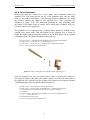
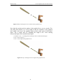
4.4.4. Lever Placement.........................................................................................................................57
4.4.5. Force Generation.......................................................................................................................59
4.5. RESULTS................................................................................................................................................59
4.6. FUTURE WORK .....................................................................................................................................61
5. DISCUSSION...........................................................................................................................................62
6. ACKNOWLEDGEMENTS ..................................................................................................................64
7. REFERENCES ........................................................................................................................................65
7.1. BOOKS ...................................................................................................................................................65
7.2. A RTICLES..............................................................................................................................................65
7.3. INTERNET RESOURCES ........................................................................................................................68
APPENDIX A. WORD LIS T....................................................................................................................70
APPENDIX B. USER’S MANUAL ........................................................................................................72
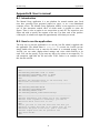
B.1. INTRODUCTION....................................................................................................................................72
B.2. HOW TO RUN THE APPLICATION........................................................................................................72
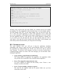
B.3. COMMON ERRORS...............................................................................................................................73
B.4. THE WORKSPACE .................................................................................................................................74
B.5. INTERACTION MODELS.......................................................................................................................76
B.6. TRIALS..................................................................................................................................................77
B.7. SHEETS.................................................................................................................................................78
B.8. FIGURES ...............................................................................................................................................79
B.9. REBUILDING THE APPLICATION ........................................................................................................81
B.10. A NALYSING THE DATA FILES ..........................................................................................................84
All trademarks mentioned in this thesis report are the property of their respective owners.
vi
Mental Grasp
1. Introduction
1. Introduction
1.1. Background
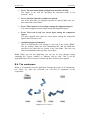
The classical Mental Rotation Test (MRT) is a cognitive test where a number of
similar, three-dimensional, geometric figures are presented to a test subject. These
figures are rotated in different dimensions in relation to each other. The subject is
then supposed to determine whether any of the figures are identical. To be able to
decide if two figures are identical or not, the subject has to perform a mental
rotation of the figures. Mental rotation tests are often used as an aptitude test to
estimate the capacity of three-dimensional thinking and spatial ability. These tests
have almost exclusively been presented printed on paper or displayed on a
conventional computer screen. The two-dimensional nature of these presentation
mediums implies that the figures are displayed in a monoscopic mode. Therefore,
only perspective depth cues are available when comparing the figures.
Experiments have shown that male subjects, in general, are better at performing
mental rotations than female subjects when figures are presented in a monoscopic
mode. Mental rotation tests performed using stereoscopic displays shows that this
difference is no longer noticeable when the subject is able to use stereoscopic
depth cues to achieve true depth-vision. These results indicate differences in
cognitive skills depending on the number of available cues. Consequently, it
would be interesting to examine how additional cues affect mental rotation skills.
From a cognitive aspect it would also be of interest to analyse how test subjects
perform the mental rotations. The only way to elicit this information at present is
to ask the test subjects. The problem is that test subjects are often unable to
express how they perform the mental rotations. One way to gather this
information would be to use dynamic figures that can be physically rotated. It
would then be possible to see exactly how the test subjects rotate the figures.
1.2. Purpose
The main purpose of this master’s thesis is to develop a generic, multi-sensory
mental rotation test platform in a virtual environment. In this test platform, the
three-dimensional, geometric figures will be presented to the test subjects in
stereoscopic mode and with haptic feedback. This means that the test subject will
both be able to view the figures using depth-vision and to touch and feel the
figures. Within the test platform it will be possible to set different test conditions
by switching stereoscopic vision and haptic feedback on/off in an independent
way. Furthermore, the test supervisor must be able to generate different test setups
using some kind of user interface. The system must also contain functionality for
saving test data for evaluating purposes.
An additional purpose is to perform a survey of the haptic field. Within this
survey we are going to identify and examine different haptic application areas.
There are two main objectives of this survey. The first objective is to provide an
overview of the haptic field at present. The second one is to find out what kind of
research that is required to be able to design functional and reliable haptic user
interfaces that utilise haptics as an efficient display technique.
1
Mental Grasp
1. Introduction
1.3. Commission/funding
This master’s thesis is a feasibility study within the programme Athena-Skill
Acquisition Lab, which is partly financed with funds from Objective 1 “Norra
Norrland” (EU Structural Funds). Athena-Skill Acquisition Lab is a joint project
involving the Department of Psychology and the Centre for Educational
Technology (CUT) with Leif Hedman as the research director. The actual work
has been performed with Tomer Shalit as supervisor at the Interaction Design Lab
(which is also partly financed with funds from Objective 1 “Norra Norrland”) at
Umeå Institute of Design as a part of a larger project. The purpose of this main
project is to study the importance of haptics for human perception and humancomputer interaction. The intention is that this master’s thesis will result in a
unique test platform for multi-sensory mental rotation tests. With this platform it
will be possible to examine how haptic interaction and stereoscopic vision affect
this isolated cognitive task. It also enables high-resolution measurements of
interaction data. The platform will be used in forthcoming master’s theses, within
the main project, to perform extensive mental rotation test studies. Hopefully, it
will be a useful tool and lead to new insights concerning the influence of haptics
in cognitive tasks. Regarding the survey, the intention is to use it as a basis for
further haptic research at the Interaction Design Lab.
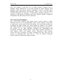
1.4. Methods and Tools
In this section, we will describe the most important tools and methods that have
been used during the development of the Mental Grasp application and the work
with the survey of the haptic field. Information sources as well as software and
hardware are covered.
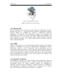
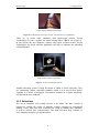
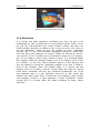
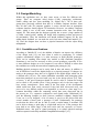
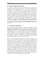
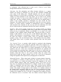
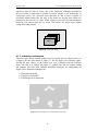
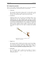
1.4.1. Reachin Display
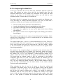
The test platform will be built upon a Reachin Developer Display from Reachin
Technologies [52], see Figure 1. This is a hand-immersive hardware platform that
integrates stereoscopic graphics and haptic feedback in a consistent, seamless
way. The display provides complex, high-quality haptic feedback through a
PHANTOM™ Premium 1.5 interaction device from Sensable Technologies [53].
Stereovision is provided by a stereo-output graphics card and a pair of
CrystalEyes® shutter glasses from StereoGraphics Corporation [54]. The screen is
directed downwards a semi-transparent mirror that reflects the stereoscopic image.
This yields an interface where graphics and haptics are totally consistent. The user
perceives an illusion of reaching into a three-dimensional workspace located
below the mirror. The graphics and the physical interaction device are perceived
as being totally co-located within the workspace. In this way, the virtual
environment is seen and felt at the exact same position.
2
Mental Grasp
1. Introduction
Image courtesy of Reachin Technologies.
Figure 1. The Reachin Developer Display.
1.4.2. Reachin API
The main software tool for creating the mental rotation test application will be the
Reachin API. This is a scene-graph based application programming interface,
specially designed for facilitating the creation of multi-sensory, interactive
applications. The Reachin API automatically manages the calculations and
synchronisation necessary for graphic and haptic rendering and simulation. The
API is built upon C++ but it also integrates Python, VRML, OpenGL and special
haptic rendering technology. It is strictly object-oriented and utilises advanced
object-oriented mechanisms.
1.4.3. VRML
VRML is an acronym for the Virtual Reality Modeling Language. The language
provides a standardised file format for modelling and representation of threedimensional, interactive, virtual environments. These environments and the
objects they contain can be static as well as dynamic. VRML is closely integrated
in the Reachin API, which in fact is structurally equivalent to VRML. Objects and
worlds can be specified in a VRML file, which is then read by the API and loaded
into an application. The main part of the visible objects in the Mental Grasp
application is modelled using VRML.
1.4.4. Borland C++ Builder
The Borland C++ Builder is an object-oriented, visual programming environment
for rapid application development. The C++ Builder 6.0 has been used during the
development process for editing, compiling, building and debugging the
application. The main reason for choosing C++ Builder was that it is currently the
only programming development environment that is supported by the Reachin
API. This is because the API requires total ANSI C++ compliance.
3
Mental Grasp
1. Introduction
1.4.5. Information Sources
In the process of writing the haptic survey we have used a large amount of
research papers. These papers were found by structured and thorough use of web
resources. The two dominating information sources are the IEEE Computer
Society Digital Library [46] and ACM Digital Library [43].
1.5. Demarcation
As mentioned above, the main concern of this master’s thesis is to develop a test
platform for mental rotation tests and to perform a survey regarding the field of
haptics. It is outside the scope of this master’s thesis to use the application for any
real mental rotation tests; this will be done in forthcoming master’s theses. The
survey will not include anything about haptics for the visually impaired. This is
because our main area of interest is multi-sensory applications, i.e. applications
that utilises both vision and haptics for interaction with the users. Furthermore, we
do not intend to discuss the more hardware specific areas of haptic algorithms,
since this is a very technically advanced area.
1.6. Outline
Below follows an outline of the different sections of the thesis. The sections are
all described shortly under their respective heading.
•
Essential concepts
In this section we will describe the haptic concept in human-computer
interaction. Concepts important for the implementation of the application
are also covered.
•
A haptic survey
This section holds the main theoretical part of the thesis; a survey of the
haptic field. It covers previous and current research. Different areas of
application, end user applications, haptic hardware and software are also
discussed.
•
Development of the test environment
The Mental Grasp application and its development are described in this
section. The main parts are a component diagram, the system design and
various algorithms.
•
Discussion
In this section we will discuss our findings from the haptic survey, some
conclusions will also be drawn.
4
Mental Grasp
2. Essential Concepts
2. Essential Concepts
The purpose of this section is to give a definition of haptics and explain what it is
all about. Concepts related to the implementation process and the Reachin API are
also described.
2.1. Haptics
There exists a wide variety of different definitions of the word “haptic”. The
common thing for these definitions is that they all relate to the sense of touch. On
the basis of the touch modality, different definitions are suitable in different
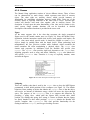
contexts. The following definition is from the Merriam-Webster online dictionary
[48].
Pronunciation: ‘hap-tik
Function: adjective
Etymology: International Scientific Vocabulary, from Greek haptesthai to
touch
Date: circa 1890
Relating to or based on the sense of touch
The Merriam-Webster definition of the haptic concept is general and versatile
since it relates to all aspects of touch. Another definition more suitable in the
context of this thesis is a slightly altered version of the definition on whatis.com
[56].
Haptics (pronounced ‘hap-tiks) is the science of applying tactile and
kinesthetic touch sensations and control to interaction with computer
applications. The word derives from the Greek word haptesthai, which
means “to touch”. By using special input/output devices such as joysticks,
data gloves, or other devices, users can receive feedback from computer
applications in the form of felt sensations in the hand or other parts of the
body.
What this definition really says is that haptics allow us to interact with computer
applications by literally touching and feeling virtual objects that only exist in
digital form. The haptic concept in this context is often referred to as force
feedback. The definition also states that haptics enable us to perceive two main
types of touch feedback. The first type is tactile feedback, which applies direct
stimuli to the skin. It enables us to feel sensations such as vibration, pressure and
textures. The second type is kinesthetic feedback, which stimulates various
sensors located in muscles, tendons and joints within our body. Kinesthetic
feedback simulates touch sensations such as weight and resistance. In
combination, these types of touch feedback are able to simulate and apply a wide
variety of touch sensations to the user [2].
5
Mental Grasp
2. Essential Concepts
2.2. Scene Graph
The scene graph is an important concept when working with virtual reality and
three-dimensional worlds. It can be described as a hierarchical data structure that
defines a three-dimensional scene. More specifically, the scene graph is a
directed, acyclic graph, which is used to group objects in the scene in a
hierarchical way according to their spatial location. Using a scene graph for
structuring the virtual world offers performance improvements compared to
grouping objects in a linear list. If the virtual world is large, for example, the
processes of rendering and determining which objects are visible (culling) can be
made more efficient. Instead of testing every object for culling, only certain parts
of the scene graph have to be tested [3].
The main building block of a scene graph is called a node (see section 2.3). The
internal nodes of the scene graph are used to group related objects in the scene.
Each internal node has an arbitrary number of children nodes. At the bottom, the
scene graph contains leaf nodes. The leaf nodes hold the shape, geometry and
appearance attributes of the objects that are visible in the world. The scene graph
concept makes it easy to express relationships between objects in the world.
Objects can be grouped within shared coordinate systems such that movements
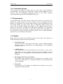
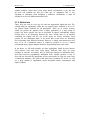
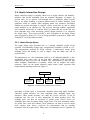
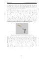
and rotations will not disturb the relationship between related objects [3]. Imagine
modelling a chess set for example. When moving the entire chessboard, all of the
pieces shall remain in their places, but it must also be possible to move each piece
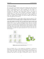
independently. A possible scene graph representation for a part of the chess set is
shown in Figure 2.
Image courtesy of Reachin Technologies.
Figure 2. The scene graph representation for a part of a chess set
containing the board, one castle and one pawn.
Since the Reachin API is a tool designed for development of multi-sensory
applications, its scene graph has some special characteristics. To be able to see, as
well as touch objects in the world, they must be rendered with both graphics and
haptics. Both the graphic and haptic rendering engines need to work with
geometrical data from the scene graph. As described in section 2.5, these two
6
Mental Grasp
2. Essential Concepts
types of rendering are performed in two separate event loops. Therefore, the
Reachin API uses a multi-sensory scene graph. This means that it utilises one
single scene graph, which shares its data between graphic and haptic rendering.
The multi-sensory scene graph avoids problems related to mutual updating and
synchronisation which arise when using one copy of the scene graph for each type
of rendering [3].
2.3. Nodes and Fields
Nodes and fields are the two most important building blocks in the Reachin API
scene graph. Both of these concepts are inherited from VRML and the Reachin
API uses a scene graph, which is structurally equivalent to the VRML scene
graph. In this way the API offers a structure, which is completely consistent with
the widely used VRML standard.
The node is the main building block in the Reachin API scene graph. It can be
abstractly described as a building block, which contains certain attributes. Nodes
are used to define and describe objects in the virtual world. Individual nodes can
for example describe viewpoints, light sources, shapes, colours and so on. The
second most important building block in the scene graph is the field. Fields are
entities that define and store the attributes of the nodes. Each field belongs to a
particular node. Different types of nodes contain various numbers of fields. Every
field has a default value, which is used unless its value is explicitly set. One thing
that can be a bit confusing is that nodes and fields can have the same name. This
is because a field of one node can store another node as its value. Therefore, it is
important to distinguish between nodes and fields. If a field shares its name with a
node, that field is always used to stores instances of the corresponding node [1, 3].
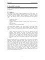
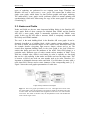
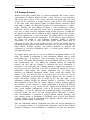
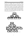
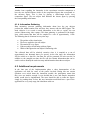
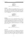
Figure 3 shows the scene graph representation of a cubic box.
Image courtesy of Reachin Technologies.
Figure 3. The scene graph representation of a box. The highest-level node of the
box is the Shape node. The appearance and geometry fields of the Shape node refer
to other nodes. The material field of the Appearance node refers to a node with the
same name. The fields of the Box node, the SimpleSurface node and the Material
node contain single values.
7
Mental Grasp
2. Essential Concepts
The Reachin API includes various augmentations compared to VRML. Standard
VRML is exclusively used for displaying graphical world representations,
interactions and behaviours. In addition to this, the Reachin API also includes
nodes and fields, which define haptic properties. These augmentations preserve
the structure of the scene graph so that it is still structurally equivalent to the
VRML scene graph. In this way haptic properties can be integrated directly within
a scene in a VRML manner [3]. The SimpleSurface node in Figure 3 is a haptic
node, which defines a simple touchable surface.
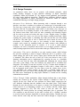
2.4. Event Handling
The scene graph and its nodes are structures designated for describing, arranging
and structuring a scene. This representation is only a static description of the
scene. To be able to represent a dynamic world with behaviour, movements and
interactive possibilities, the scene graph must be complemented with event
handling capabilities. The basic event handling mechanism of the Reachin API is
the field network. As the name suggests, the basic idea of the field network is to
link fields and their values together. This provides possibilities to express
dependencies between different data. Both fields within a single node and fields in
multiple separate nodes can be linked together. This is done by creating a route. A
route can be described as a directed connection, which passes the value of the
source field to the target field. The simplest type of dependency is to link two
fields together directly. When the value of the source field is changed, like in this
case, the value of the target field gets updated. This type of routing requires that
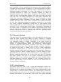
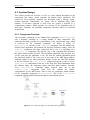
the two fields are of the same type. Figure 4 shows a graphical example of a direct
route.
Image courtesy of Reachin Technologies.
Figure 4. A direct route from a field in one node to a field in another node.
Direct routing between fields is an efficient way to express simple dependencies.
This is not very general though. It does not offer any possibilities to process or
manipulate the field values. For this purpose, the Reachin API offers a building
block called function field. Function fields are equivalent to normal value bearing
fields except that it is possible to specify their value. The value of a function field
can be defined as an arbitrary function of its input fields. It can be seen as an
intermediate object, which performs necessary calculations. To use a function
field, the input fields are first routed to it. When any of the input fields are
changed, the function field performs calculations based on the input field values.
The result of the calculations is thereafter assigned as the value of the function
field. This is then sent to the routed output field. By using this building block for
node functionality it is possible to specify a wide range of behaviours. Figure 5
shows a graphical example of a function field. By using routes and function fields,
the field network provides a base for implementation of complex applications [3].
8
Mental Grasp
2. Essential Concepts
Image courtesy of Reachin Technologies.
Figure 5. The function field Avarage calculates the average value of its
two input fields. The calculated value is thereafter sent to the target field.
2.5. Graphic and Haptic Rendering
Multi-sensory applications by definition utilise several modalities for interaction.
In order to output and visualise data, it is necessary to transform the underlying
data into a representation, which is suitable for each modality. This transformation
process is called rendering. By using the Reachin API it is possible to create
applications, which use both the visual and the haptic modalities. Therefore it is
necessary to perform both graphic and haptic rendering. These two types of
rendering are very different from each other when it comes to calculation
complexity and performance requirements. To handle these differences and to
satisfy the requirements of both types of rendering, the Reachin API uses two
parallel event loops, which are run in different frequencies and executed in
separate threads. These two loops are called the scene graph loop and the realtime loop [3].
2.5.1. Scene Graph Loop
This is the most complex of the two event loops. The scene graph loop performs
all tasks and calculations, which are too time-consuming to be executed in the
real-time loop. The scene graph loop has its name from the fact that it is the event
loop that interfaces with and interprets the scene graph. These interfacing
activities include the graphics rendering and collision traversal. The collision
traversal is the part of the haptics rendering process that is too time-consuming to
be performed in the real-time loop. It is a traversal of the scene graph whose
purpose is to detect collisions between the haptic device and objects in the scene.
The scene graph loop is run as fast as possible without slowing down the real-time
loop. The update frequency depends on the complexity of the scene and on the
processor performance. In order to have a meaningful interaction, an update
frequency of 20-30 times per second is accepted [3].
2.5.2. Real-time Loop
Haptic rendering requires a much higher update rate compared to graphic
rendering. If the output forces are not updated close to a thousand times per
second, the haptic illusion vanishes. The output forces become unstable and the
user will start to experience artefacts and latency. To provide the required update
rate, the haptic rendering is executed in a separate loop called the real-time loop.
9
Mental Grasp
2. Essential Concepts
The real-time loop has a higher priority than the scene graph loop. In order to
retain a constant, high update rate, complex processing and calculations are
avoided in the real-time loop. It does not interface directly to the scene graph or
field network. To render the output forces it uses temporary and simplified
representations, which are generated in the scene graph loop [3].
2.6. Force Operators
One of the strengths of the Reachin API is that it automatically calculates,
generates and outputs haptic touch sensations when the haptic device is in direct
contact with an object in the world. When creating specific multi-sensory
applications, developers often need to create force effects, which are not explicitly
provided by the API. For example, there is often a need to use free space force
effects that do not require direct contact between the haptic device and objects in
the world. Such force effects can be for example magnetic fields, friction forces,
spring forces and vibrations. To allow implementation of this kind of force effects
the Reachin API offers force operators [3].
A force operator is actually nothing more than a mapping function from the haptic
device position to an output force in Newtons (N). This means that a force
operator uses the position of the haptic device to calculate and generate a suitable
haptic output force, which is applied to the user via the haptic device. By using
force operators it is possible to simulate practically any touch sensation the haptic
device is able to output. To provide realistic, high quality touch sensations, haptic
output forces must be updated around one thousand times per second. This means
that the force operators must be called from the real-time loop. Even though force
operators are called in the real-time loop, they are created in the scene graph loop.
Each force operator only exists for one pass in the scene graph loop. During its
lifetime, it is called several times from the real-time loop. The only time a force
operator receives information about the state of the scene graph is when it is
created. The state of the scene graph can change between the creation of two
successive force operators. This may result in a large and sudden change of the
output force, called a tic, when switching between two force operators. To reduce
this problem the Reachin API extends the lifetime of the previous force operator
for one more pass in the scene graph loop. Both the current and the previous force
operator are called from the real-time loop and the resulting output force is a
linear interpolation between them. In this way, two force operators always work
simultaneously to provide stable output forces [3].
10
Mental Grasp
3. A Haptic Survey
3. A Haptic Survey
This section is an extensive, though not all-embracing, survey of the field of
haptics within human-computer interaction. The purpose of the survey is to
identify and examine previous, as well as current, work, research and
development within the field. Areas spanning from human factors to haptic
hardware devices are covered. Various application areas and end user applications
are also discussed. By examining previous work and the field at present the
ambition is to identify what kind of research efforts are required, in order to
evolve, improve and facilitate haptic interaction design. This concept refers to the
design of user interfaces, which include haptics, as well as the design of haptic
interaction hardware. Hopefully, the survey can be used as a foundation for
further haptic research. It can be considered as an independent part of this report
and can therefore be read separately.
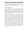
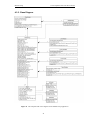
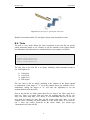
3.1. Overview
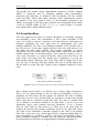
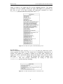
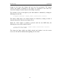
The figure below provides a model of the current haptic field. Each one of the
sub-areas contained ni the figure will be covered, described and discussed in this
survey.
Vehicle Sim.
Haptic
Interaction
Design
Medical Sim.
Simulation/
Training
Medicine
Sensorics
Environment
Physics/
Chemistry
Scientific
Visualisation
Devices/
Techniques
Prototyping
Human
Factors
Design/
Modelling
Haptics
Digital Clay
Shared
Environment
s
Teleoperation
Entertainment
Telemedicine
Telerobotics
Figure 6. A model of the current haptic field.
11
Mental Grasp
3. A Haptic Survey
3.2. Simulation/Training
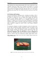
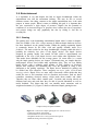
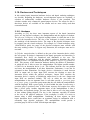
Virtual reality has been used in simulators for quite some time now as a fully
accepted tool. It has been shown that it is much safer and cheaper to have people
train in simulators compared to letting them train in real situations. Today, you
can find simulators for just about anything, but the word “simulator” is perhaps
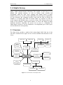
most associated with various types of vehicle simulators. Many of these are flight
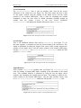
simulators (see Figure 7), but there are also simulators for trains, ships, cars, all
sorts of military vehicles and so on. Not all of these simulators incorporate haptic
force feedback, but it still shows that there is a large interest for simulators in
general. It is easy to understand why simulators have become so popular; neither
the user nor the equipment is at any risk. Furthermore, a simulator often costs less
than the actual vehicle.
Image courtesy of Saab Avionics AB.
Figure 7. Swedish Air Force Combat Simulation Center.
Even though the vehicle simulators seem to be the largest group within the
simulation area, more and more application areas are starting to show an interest
in simulators and how to use them for training and education. One of these areas
is surgery and medicine in general. There is also research going on in areas such
as assembly [4] and dental training [50].
3.2.1. Possibilities and problems
What are the advantages of using a training simulator then? Well, there are a
number of reasons. As already mentioned, it can be much safer and cheaper
compared to training in real situations. A training simulator gives you the
possibility to train dangerous and/or advanced procedures in a virtual
environment. You do not risk damaging expensive equipment, or, even worse,
hurting or injuring someone. A training simulator does not only offer the
possibility of practising entire procedures; isolated motor skills can also be
trained.
12
Mental Grasp
3. A Haptic Survey
Using a training simulator will also increase the efficiency of the training, since it
reduces the need of a supervisor being present at all times during the training
session. The user can train in the simulator as often as he or she wants, not only
when there is a supervisor available. Another positive thing is the fact that the
exact same training situation can be reproduced over and over again. A medical
simulator will also reduce the stress exposure for both the student and the patient,
since the latter no longer has to be involved in the training.
Within the field of surgery, it has been shown that training in a simulator will give
the same effect as training in the real world on a real patient [21]. This means that
there is a transfer of skills from the training in a simulator to the real task.
Research within laparoscopic surgery, or minimally invasive surgery, indicates
that training in a virtual world might even be better than conventional surgical
training, or at least that students training in a simulator performed more correct
incisions and less incorrect incisions than those who had received conventional
education [21]. There is also research showing that a certain virtual reality
surgical simulator can be used as an “… objective assessment tool for evaluating
psychomotor skills for laparoscopic surgery” [15]. This means that the simulator
was able to distinguish between skilled laparoscopic surgeons, junior laparoscopic
surgeons and novices. As of yet, there is no research, which indicates whether or
not haptics can improve the simulations. But it seems probable that simulators for
tasks that require manual manipulation (such as surgery or assembly) should
benefit from haptic force feedback [4].
3.2.2. Actors and products
There are a lot of different simulators on the market. However, there are not so
many with haptic feedback. Not very surprisingly, most of the simulators with
haptic feedback seem to be medical applications. Many medical simulators
require the user to be able to touch and feel, which is not always the case with a
vehicle simulator for example. This implicates that the simulators described here
will be mainly medical simulators.
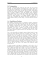
At present, there is one type of medical simulator, which receives almost all the
attention, namely simulators for minimally invasive surgery, or laparoscopic
surgery (which is the actual medical term). Not all of them integrate haptic
feedback, though. There exist a number of commercially available simulators for
laparoscopic training on the market, among these there are three Swedish
products. Reachin Technologies [52], Mentice Medical Simulation [49] and
Surgical Science [55] all have laparoscopic training systems. Currently, only
Reachin’s product has haptic feedback (see Figure 8). However, Mentice Medical
Simulation is working on implementing haptics in their system.
13
Mental Grasp
3. A Haptic Survey
Image courtesy of Reachin Technologies.
Figure 8. The Reachin Laparascopic Trainer. The dissection of a gallbladder.
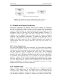
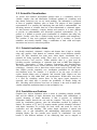
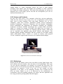
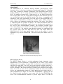
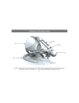
There are of course other simulators than laparoscopic trainers. Novint
Technologies [51] has a product for dental training called VRDTS (see Figure 9).
In this system, the user diagnoses, removes and repairs occlusal cavities. Novint
Technologies also hopes that this application will help to automate the generation
of dental implants.
Image courtesy of Novint Technologies.
Figure 9. Novint Technologies VRDTS.
Another interesting system is being developed at VRlab at Umeå University. They
are constructing a haptic wheelchair simulator, which is to be used in their Stroke
simulator as a means of navigation. Servomotors mounted on a regular wheelchair
will provide the force feedback.
3.2.3. Reflections
The use of simulators will certainly increase in the future, but more research is
required to validate the results of simulator training compared to conventional
training. Today, more and more companies are trying to validate their simulators,
in order to increase their competitiveness. This trend will most likely continue, as
new companies attempt to get into the market.
14
Mental Grasp
3. A Haptic Survey
Medical simulators with haptic feedback will probably continue to grow in use
and popularity, since they offer an effective and safe way of training medical
procedures, which previously required an actual patient. Today, most
manufacturers of medical simulators are trying to make the simulation as “real” as
possible. Advances in graphics hardware as well as raw processing power have
made it possible to simulate for example soft tissues and fluids in a very realistic
way. In combination with haptics to provide touch, this means that training in a
simulator can be experienced almost as real as ordinary training on a patient.
However, is it certain that this is the best way to train? Do we really need all this
realism? Should we not instead focus on the skills needed to perform a certain
procedure? Perhaps it is better to make smaller “training modules” to train motor
skills instead of focusing on realism and entire procedures. As we have already
mentioned, further research is required within this area before any definite
answers can be given.
15
Mental Grasp
3. A Haptic Survey
3.3. Scientific Visualisation
As science and technical development advance there is a cumulative need to
visualise complex data and information. Traditional methods for visualising such
data almost exclusively rely on our visual modality. The information is presented
in form of graphical diagrams, plots or charts. The purpose of these graphical
representations is to structure the underlying data and make it understandable. An
increasing amount of scientific data has a three-dimensional or volumetric nature.
As data becomes volumetric, complex, abstract and extensive, it is more difficult
to provide an understandable and foreseeable graphical representation [31]. In
general, it is difficult to provide good visualisations of volumetric data using only
graphics. Usually, such data is rendered using layered graphics and transparency.
The problem is that such graphical renderings have a tendency to become
unintuitive and visually cluttered. Using a combination of both visual and haptic
interaction can, however, reduce this problem.
3.3.1. Potential Application Areas
As already mentioned, volumetric, complex and abstract data is hard to visualise
using only graphics. Such datasets are common within several different scientific
areas. We have identified four main areas where haptic visualisation has a
potential for being especially useful. These areas are medicine, environment,
physics/chemistry and sensorics. Within medicine there is a great need for
providing accurate visualisations of volumetric data such as MRT-data (Magnetic
Resonance Tomography), CT-data (Computer Tomography) and ultrasound-data.
The environment area covers several sub-areas such as meteorology, geology and
seismology. Sensorics refer to data from various sensors such as radar and sonar
data. Haptics provide completely new visualisation possibilities for the physics
and chemistry areas. For example, it is possible to use the sense of touch to
explore abstract things such as magnetic and electrical fields. Haptics can also
advantageously be used within fluid- and aerodynamics. Within these areas there
is a need for visualising various flows. In this aspect, haptic interaction is
especially well suited since it provides the possibilities of literally feeling the
flow. One thing, which all these areas have in common, is the need to handle and
visualise volumetric, multivariate data in a clear and intuitive way.
3.3.2. Possibilities and Problems
Graphics have obvious limitations when it comes to visualising complex scientific
data, and the addition of haptic interaction may facilitate such visualisations. A
general advantage of haptic interaction is that it provides an additional
information channel between the user and the computer. This may be especially
useful for visualisation purposes, since the information provided by graphics is
limited. The authors of [7] and [33] mention another general advantage associated
with haptic interaction. In everyday life both vision and touch are used for
exploration and task handling. This makes haptic interaction a natural and
intuitive way to gain information and understanding. Multi-sensory interaction,
including haptics, has also benefits more specific to visualisation. One such
benefit is that different attributes of the underlying data can be mapped to
16
Mental Grasp
3. A Haptic Survey
different senses [7, 33]. For example, imagine a volumetric dataset consisting of
weather data for a certain area. This data is multivariate in the sense that it
contains several important factors. For example, both air temperature and air
pressure are of interest. The problem is that it is difficult to visualise both
attributes simultaneously using graphics. This problem can be solved by mapping
temperature to colour graphics and pressure to haptics. Consequently, it is
possible to present a larger amount of information using both graphics and
haptics. Another visualisation-specific advantage is that haptics is well suited for
indicating structural information in data [31]. Haptic barriers and different
resistance levels can indicate limits and boundaries in data.
Although haptic interaction has a potential for improving and facilitating the
understanding of complex scientific data, there are also problems and challenges.
One drawback, related to the nature of haptic interaction, is that the user only can
touch a limited part of the data at once [37]. Consequently, it becomes difficult to
get a haptic overview of the data. This drawback is worsened by the fact that the
majority of the current haptic systems use single-point interaction. This means
that the user can only interact with one point at a time. When applying both haptic
and graphical interaction, however, this is not a severe problem. Graphics
provides the necessary overview that the haptics lack. A problem when
representing volumetric data is that haptic output forces are usually based on
graphics. Graphics is further represented by polygon surfaces. A surface-based
generation of haptic output forces is not always sufficient to represent continuous
internal structures of the data set [36]. High-quality haptic representation of such
data may require other, more complex rendering techniques. Another important
issue to be dealt with is how to visualise abstract data using haptics. The problem
is how to present data, which has no corresponding concrete concept, in an
understandable way. Even if output forces can represent the data, the user must
still know what the forces mean and how to interpret them [33]. Research is
needed to find appropriate metaphors, which describe how to perform mapping
from abstract data into haptic output in an effective and understandable way.
3.3.3. Actors and Products
Despite the potential for haptics within scientific visualisation, there do not exist
many end user products on the market at present. The only companies, which
have invested in haptic visualisation tools in any larger scale, are various
petroleum corporations. The Norwegian oil company Norsk Hydro in cooperation
with Reachin Technologies from Sweden are developing a product for threedimensional, haptic well-path planning. This product goes under the name “Well
Path Planner” (see Figure 10) and will result in a commercial product in early
2003.
17
Mental Grasp
3. A Haptic Survey
Image courtesy of Reachin Technologies.
Figure 10. Screenshot from the Reachin Well Path Planner application.
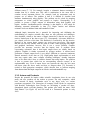
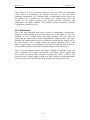
Another company, which is creating haptic visualisation tools for the petroleum
industry, is Novint Technologies. The VoxelNotepad is a commercial product for
volumetric oil exploration and reservoir and well path modelling (see Figure 11).
The application is currently under development. VoxelNotepad will support
volumetric datasets from commercial oil reservoir modelling programs. The
intention is to use it as an everyday tool in the oil production process.
Image courtesy of Novint Technologies.
Figure 11. Screenshot from the Novint VoxelNotepad application.
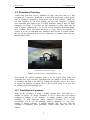
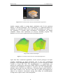
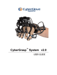
Apart from these commercial applications, several research prototypes for haptic
scientific visualisation are being developed. One of the most sophisticated
prototypes is the nanoManipulator [41] (see Figure 12) at the University of North
Carolina at Chapel Hill, USA. The nanoManipulator is a graphic/haptic user
interface for scanned-probe microscopes (SPM). SPMs are microscopes that allow
exploration and manipulation of surfaces to an atomic scale. The nanoManipulator
translates subject data from the SPM into a 3D-surface haptic model scaled by a
factor about a million to one. The user is then able to explore and manipulate the
subject in an immersive environment. Among other things, the nanoManipulator
is being used to explore various viruses and proteins.
18
Mental Grasp
3. A Haptic Survey
Figure 12. The nanoManipulator interface.
3.3.4. Reflections
It is obvious that haptic augmented visualisation tools have not had its big
breakthrough yet. This is probably due to several different reasons. Firstly, it does
not exist any well-documented and verified scientific evidence that shows the
benefit of haptic interaction. In addition to this, it does not exist a wide variety of
end user applications, which can show the strengths of haptic visualisation.
Secondly, this is a new and unevaluated visualisation technique. It usually takes
some time before new techniques are accepted. Thirdly, the tools that do exist are
very expensive. Even if potential users are interested in testing the new technique,
they are not willing to spend a huge amount of money. It is interesting though,
that companies within the petroleum industry seem to be willing to invest in this
new technique. As they have almost unlimited resources at their disposal, they
have the potential to develop this visualisation technique. If one actor is willing to
invest in the technique, others will probably follow. It is obvious that this
technique still is in its infancy. Extensive research efforts and testing are required
before haptic visualisation will have any commercial breakthrough. One of the
most important tasks is to gain knowledge about how to map various data
attributes into haptic output forces. General rules and metaphors, which describe
such mappings, would be of great importance to haptic visualisation. Another
essential task is to develop stable and reliable techniques for haptic volume
interaction.
19
Mental Grasp
3. A Haptic Survey
3.4. Teleoperation
The field of teleoperation has existed for quite some years now and the
application areas include hazardous environments such as nuclear plants, outer
space and deep-sea exploration [24, 34]. In addition, teleoperation is also used in
non-hazardous areas such as surgery [42] and other areas, which “demand human
intervention for monitoring and detection of abnormalities” [24]. Teleoperation
makes it possible for humans to explore and manipulate remote environments
without actually having to be on location. The advantages are obvious; dangerous
environments, e.g. deep oceans or outer space, can be explored without risking
human lives. Unsafe workplaces, e.g. oil drilling platforms or mines, can be
operated from a comfortable office. Surgeons can perform operations/surgery on
patients situated in another part of the country, or even from the other side of the
world.
3.4.1. Possibilities and Problems
When building a teleoperation system, it is important to make the operator/user
feel as if he or she is physically present at the remote site. This is often referred to
as “telepresence” [24, 34]. This is where haptics enters into the picture, since
haptic feedback is important when there is contact at the remote site, especially
when performing precision work or when working in fragile or delicate
environments, e.g. in surgery or assembly. It has been shown that when haptic
feedback is used in robotic surgery, it considerably reduces both the average
forces and the peak forces applied to sensitive tissue. The number of errors is also
greatly reduced [42].
There is also the possibility of altering the amount of haptic feedback. It seems
obvious that different materials should have feel different, like in reality. This
means that the user does not have to rely on vision alone when it comes to
separating two or more materials from each other. In reality, a surgeon can
separate two different tissues simply by touching them. The surgeon receives the
same information from both vision and touch; the information is redundant. For
some actions it may be of interest to give more haptic feedback than there actually
would be in reality. This could, for example, be applied to surgery, where you
could define sensitive tissue to be protected, which would make it seem hard as a
rock to the surgeon performing the operation via a surgical robot. Such a robot
could also filter out any tremors in the surgeon’s hand, making the surgical
operation safer [5].
A problem associated with haptics in teleoperation is the fact that a lot of
information has to be transferred back and forth between the local and the remote
site. The haptic loop typically runs at 1000Hz, or at least at several hundred Hz.
This means that the sensors on the robot at the remote site have to send
information about position and force back to the local site one thousand times per
second. The information is then used at the local site to provide haptic feedback to
the user/operator and to update the graphics. Information is also sent the opposite
way; the operator sends movement instructions to the robot at the remote site. It is
easy to understand that even very small network latency would be unfortunate,
since that could ruin the synchronisation of the movements of the robotic arm, the
20
Mental Grasp
3. A Haptic Survey
haptic feedback to the operator and the graphics. This, in turn, could lead to a very
“unrealistic contact force feeling” [24]. A solution to this problem is to use the
notion of force-reflection, which means that the virtual forces are generated
locally, instead of receiving the actual forces from the sensors on the robot at the
remote site [24, 34]. Naturally, this implies that there has to be a very accurate
mapping between actual forces at the remote site and the virtual forces at the local
site.
3.4.2. Actors and Products
The field of teleoperation is definitely not new. According to the authors of [29] it
originated in the first part of the 20th century. At that time it was mostly used by
the military to minimise the risk of accidents when dealing with radioactive
material or other dangerous substances. The first teleoperation devices were
purely mechanical and their purpose was to “manipulate (handle and move)
objects at a distance” [29]. The next step in the development of teleoperation
techniques was the addition of electronics, which made teleoperation more widely
used in the industry. In the 1970s, the introduction of computers to teleoperation
made it possible to program the devices, which in turn rendered telerobotics
possible [29].
The introduction of haptics to the field of teleoperation is still in its infancy; there
are not many commercially available teleoperation products with haptics on the
market. However, most teleoperation systems have to be custom-built, which
means that there probably exist industrial or military teleoperation systems with
haptic feedback, even though such information is hard to find. The only
commercial teleoperation system with haptic feedback we have actually found is
from Novint Technologies. They are developing a system for simulation and
steering of an underwater vehicle, which is to be used in deep-sea exploration (see
Figure 13). However, there exist commercially available surgical robots without
haptic feedback on the market, such as the Zeus Robotic Surgical System from
Computer Motion [44].
Image courtesy of Novint Technologies.
Figure 13. Telerobotic Underwater Vehicle Control from Novint Technologies.
21
Mental Grasp
3. A Haptic Survey
There seems to be a lot of research going on in the area, much of it concerning
various forms of telemedicine, for example telesurgery [9, 42] and remote
ultrasound examinations [16]. Different kinds of teleoperated robotic devices are
also getting a lot of attention (see for example [22]). Another large part of the
research on the subject concerns more general problems associated with
teleoperation and haptic feedback. This includes network distribution problems
[29] and force reflection [24, 34].
3.4.3. Reflections
One of the most interesting areas when it comes to teleoperation is telemedicine,
which is a rapidly growing area (see for example [6]). In the future, we will most
definitely see more surgical robots with haptic feedback. Not only when the
patient and the surgeon are separated geographically. Surgical robots with haptic
feedback will without doubt be used even when the patient and the surgeon are on
the same location. This is simply because the surgical operations will be safer
when a surgical robot is used. However, this does not mean that there will be no
need for human surgeons in the future, but that the surgeon’s tools will improve.
The use of teleoperation systems with haptic feedback in hazardous areas and
unsafe workplaces will certainly also increase in the future. Special vehicles with
force sensors will perhaps allow scientists to actually feel what it is like to walk
around on Mars, without actually having to be there. Robots for disarming bombs
can also be improved by providing the sense of touch to the operator and so on.
22
Mental Grasp
3. A Haptic Survey
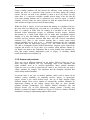
3.5. Design/Modelling
Within this application area we have come across at least five different subgroups. These are computer aided design (CAD), prototyping, architecture,
surface editing and free form modelling (or “digital clay”). All of these subgroups have previously suffered from lack of a suitable computer interface. Since
they all deal with 3D computer graphics, it seems obvious that an appropriate
computer interface should support 3D interaction. However, an ordinary computer
mouse, which is one of the most common interaction tools, does not directly
support 3D. This means that the designer typically has to move a large number of
so called “control points” making the design time-consuming, tedious and most of
all non-intuitive. Thus, the interaction tool should definitely support 3D. By also
adding haptic feedback we can make the work feel more natural and intuitive [12,
26], since the designer then can have a physical interaction with the object being
manipulated.
3.5.1. Possibilities and Problems
According to Dachiile IX et al, the addition of haptics can improve the efficiency
of the design work [12], not least when it comes to prototyping. To evaluate
complex (mechanical) designs it is often necessary to build physical prototypes.
These can be anything from simple clay models to fully functional prototypes.
Sometimes it can even be necessary to have several prototypes, especially if two
or more different designs are to be compared. It can also be difficult to ensure that
the conditions are exactly the same when comparing the prototypes [10].
Building physical prototypes can be costly, both in time and money. In addition, it
can be difficult to convert the digital design to a physical prototype. If changes are
made to the prototype, these have to be applied to the digital design, which can be
a difficult task [10] too. The various difficulties associated with prototyping often
mean that prototypes are not used until very late in the design process [10]. This,
of course, is not good. Prototypes should be used in order to evaluate the design
and to check it for possible errors. Using prototypes only in the later stages can
have serious consequences. Errors made in the first stages of the development,
which could have been easily corrected if they had been discovered early, can
prove to be very difficult, maybe even impossible, to correct at a later stage. It is
common knowledge within the computing society that errors discovered late in
the process are very expensive compared to errors found earlier. Hollerbach [19]
gave the following example (we have, however, modified it slightly). Imagine that
a new car is to be designed. A lot of money is put in to the project and after
several months of hard work a prototype is built. Unfortunately, the prototype
reveals that the driver will not be able to reach a certain button; a mechanic will
not be able to change a spark plug or a light bulb and so on. If the prototype had
been built at an earlier stage it had been easier and less expensive to correct.
Hollerbach states, “the goal of virtual prototyping is to replace physical mockups
with less expensive and easily modifiable computational mockups” [19].
23
Mental Grasp
3. A Haptic Survey
Adding haptics to virtual prototyping reduces the need to build physical
prototypes, since haptics gives the designer the possibility to touch, experience
and evaluate the design continuously. This means that prototyping can become an
integrated part of the design process and that the development cycle will be
shortened considerably [12].
3.5.2. Actors and Products
We have only come across a few companies, which have end-user applications
within this area. However, there seems to be a lot of applications at the research
stage, most of them regarding CAD with haptic interfaces [10, 18, 30].
Companies, which have end-user applications, include Novint Technologies,
Sensable Technologies, Immersion Corporation [47] and Reachin Technologies.
Novint Technologies has applications for automotive modelling, tire modelling,
architecture and layout. Sensable Technologies has a product called “Freeform”,
which is a product for creating 3D models with digital clay (see Figure 14).
Immersion Corporation has products for digitising physical objects, which then
can be interacted with haptically using special software and hardware. The
Swedish company Reachin Technologies AB has a product for 3D surface editing
called “3DH Surface Editor”, which is a version of T-Surf’s CAD program
“Gocad”, modified to support haptic interaction via a standard Reachin Display.
Image courtesy of Sensable Technologies.
Figure 14. Freeform from Sensable Technologies.
3.5.3. Reflections
Despite the fact that haptics seems to have the ability to make digital design work
more efficient and more intuitive, there has been no real breakthrough. There exist
very few end-user applications, even though a lot research has been done. The
reasons for this are not obvious, but maybe the technology is considered to be too
new and/or too expensive. If this is the case, we will certainly see more
applications in the future, as the technology becomes more accepted and the
prices go down. Haptics is yet to be discovered by the manufacturers of
conventional CAD and modelling programs. We believe that this application area
has a large potential of growing rapidly when this happens.
24
Mental Grasp
3. A Haptic Survey
3.6. Entertainment
It is legitimate to say that haptics has had its largest breakthrough within the
entertainment area and the amusement industry. This may be due to several
different reasons. One thing, common to the whole entertainment area, is the main
purpose to amuse people. When it comes to fulfilling this goal, it is important that
the user experiences a high degree of presence. Haptics has the potential to
contribute to an increased degree of presence since it allows the user to experience
and perceive things not only graphically but also by feeling it. Just like in
everyday life.
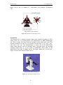
3.6.1. Gaming
The gaming area is the dominating entertainment branch when it comes to haptics.
Since the middle of the 90’s a large amount of different haptic hardware devices
has been introduced on the gaming market. Within the gaming community haptics
is commonly known by the more vivid and popular scientific name force
feedback. The main reason for the large breakthrough of haptics within this area is
probably the relatively low price of the haptic devices. The haptic devices
designed for gaming usually cost around 50-200€ which is approximately one
hundredth of the cost of the haptic devices used within other application areas.
This makes them affordable for the average gamer. Of course there is a reason
why the haptic gaming devices are cheaper. Consistently they are simpler than the
multi-purpose devices used within other application areas. They are low fidelity
haptic devices with a relatively small number of DOF (degrees of freedom).
Despite their simplicity and limitations they have the potential to bring a new
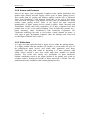
dimension to the gaming experience. The haptic devices intended for gaming can
be divided into four categories. These categories are mice, pads, joysticks and
steering wheels. Haptic mice are most often vibro-tactile which means that they
enable the user to feel sensations such as vibrations and textures. Pads are hand
controllers containing electrical motors, which make them rumble and shake.
Therefore they are often called “rumble pads”. Joysticks and steering wheels are
different from mice and pads since they are able to provide kinesthetic as well as
tactile feedback. This means that they can simulate touch sensations such as
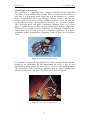
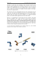
weight and resistance [11]. Figure 15 shows a collection of haptic gaming devices.
Images courtesy of Logitech and Saitek.
Figure 15. A collection of haptic gaming devices. The devises are:
- Touch Force Mouse from Saitek
- P2500 Rumble Force Pad from Saitek
- WingMan® Strike Force™ 3D joystick from Logitech
- MOMO® Racing wheel from Logitech
25
Mental Grasp
3. A Haptic Survey
3.6.2. Actors and Products
Most of the larger game development companies today market applications that
include haptic features and that support various types of haptic gaming devices.
This pertains both PC gaming and different gaming consoles such as Microsoft
Xbox, Sony PlayStation 2 and Nintendo GameCube. At the end of 2002 there
exist more than 500 games using haptics and more than 20 manufacturers, which
produce haptic gaming devices. Some of the largest and most successful
manufacturers of haptic gaming devices include Logitech, Saitek, Microsoft and
ThrustMaster. Despite their being competitors, all of these companies base their
product more or less on the same technology. They all build their products on a
haptic technology called TouchSense™ from Immersion Corporation. The
TouchSense technology has more or less become a haptic standard for games. A
wide range of game development companies utilise the technique and it has been
an official part of DirectX since version 5.
3.6.3. Reflections
It is quite clear that haptics has had its largest success within the gaming industry.
It is highly probable that this situation will continue to prevail unless the price of
the multi-purpose haptic devices used within other application areas drops
significantly. One thing that would be interesting is if those advanced, high
quality devices reached a price level, which made them available for gaming
purposes. This would open entirely new possibilities for game interaction.
Another contributing reason to the unique position of the gaming area is that no
scientific evidence, showing the benefits of haptic interaction, is needed. The only
justification necessary for haptics is that it makes gaming more fun.
26
Mental Grasp
3. A Haptic Survey
3.7. Shared Virtual Environments
The research on haptics within virtual environments has previously almost
exclusively dealt with single user systems. Now, more and more research focuses
on haptics in virtual environments for two or more users, so called shared
environments. A lot of attention is paid to the subjective feeling of presence and
how to achieve this in a shared virtual environment. Presence in single user
environments is often defined as “the feeling of being there”. But when it comes
to shared environments, you also want to make the users feel as if they are
together in the virtual environment. The users should be able to interact, not only
with the environment, but also with each other. Furthermore, the users should be
able to “display their actions and express their emotions to each other” [8]. This
augmented form of presence has been given many different names, such as
“togetherness”, “co-presence” or “social presence”. In this report we will hereafter
use the term “co-presence”. Shared environments have many potential application
areas; they can be applied to any virtual environment where you want the users to
have a common, or mutual, experience. This includes distributed meetings, virtual
prototyping, online museums and anywhere else where collaborative tasks are to
be performed.
3.7.1. Possibilities and Problems
Previous research has shown that presence in single user environments can be
increased with “high graphics update rate, low latency, wide field of view and [a]
high degree of interactivity” [13]. Of course, the same applies to shared
environments. But how can we increase the sense of co-presence? Durlach and
Slater claim that the sense of co-presence will increase if changes made to the
environment by one user are clearly perceptible by the other users. Manipulation
of the environment as a result of several users cooperating can have an even
greater effect on co-presence [13]. Basdogan et al [8] have shown that adding
haptic feedback to a shared environment increases the feeling of co-presence and
task performance. Sallnäs et al [38] show similar results; haptic feedback
increased task performance as well as presence and co-presence.
There are of course many problems associated with shared environments. If the
users are located at different geographical sites you will have problems with
network latencies. In the average case you will not have a dedicated network
connection; you will most probably have to use already existing networks, such as
the Internet. This means that you cannot control the traffic on the network; access
times will vary from time to time. Since the use of haptics requires a lot of
information to be sent back and forth, it is easy to understand that a slow network
connection can be a potentially large problem. This problem will of course
increase with the number of users, since the information has to be sent to all actors
in the shared environment. Hespanha et al [17] suggest a solution by introducing
“groups”. Users residing on hosts that are close to each other (with low
communication latency) are put into fast local groups. Within the local group,
users can interact with each other and the environment in a non-restricted way.
Users with a high communication delay are only allowed a slower form of
interaction; they can touch and feel objects but they cannot apply forces to them.
Even though this is not an optimal solution, it could still prove useful.
27
Mental Grasp
3. A Haptic Survey
Another problem, which arises when using shared environments, is the fact that
all users will probably not have the same type of equipment. This is very
important to remember when designing a multi-user environment; it must be
possible to use several different interaction tools.
3.7.2. Reflections
There does not seem to exist any real end-user applications within this area. The
existing multi-user applications either do not support haptic feedback at all or do
not support haptic feedback for all participants. There are of course systems,
which can present the graphics from a haptic application to a large group of
people, but these systems can not be described as shared environments, simply
because there is no interaction between the users. Mostly there is an operator
controlling the haptics and the rest of the group are merely spectators. Such
systems are not distributed either, in the sense that several users are interacting
and cooperating from different locations. However, a shared environment does not
have to be of a distributed nature. It would be possible to set up a shared
environment using a single computer and have all participants in the same room.
In the future, we will most certainly see more applications, which let users interact
and cooperate with each other using haptic feedback. Still, there are some
problems to consider, for instance how to send large amounts of information back
and forth between geographically distributed users. Another problem is how to
deal with the fact that the participants will not necessarily be using the same kind
of interaction hardware. We believe that when these problems are solved, we will
see a large number of applications, which incorporate shared environments with
haptic feedback.
28
Mental Grasp
3. A Haptic Survey
3.8. Human Factors
Within virtual reality research there is a general assumption, that a more accurate
representation of physical objects provides a more immersive user experience.
This means that if objects in the virtual world look and behave like real world
objects, the user experiences a stronger sense of virtual presence. This assumption
is also often made when applying haptics in human-computer interaction. When
using haptic feedback, the interaction resembles real world interaction to a higher
degree. Therefore, the mere addition of haptics is often considered to reinforce
immersion. Thereby also improving factors such as performance, efficiency, and
error rate. In some cases this assumption might be true. However, we think that
the general conviction, that the addition of haptic feedback implies these benefits,
should be regarded with a certain reservation. Just adding haptics is no guarantee
for higher immersion and better performance. On the contrary, haptics applied in
the wrong way might as well complicate interaction, leading to reduced
performance. To be able to avoid such haptic pitfalls, human factors must be
taken into account. The concept “human factors” concerns the human physical,
psychological and cognitive mechanisms that enable us to perceive and react on
haptic stimuli. If haptic hardware and software interfaces are designed and
constructed to suit these mechanisms, there is a much greater chance of the
assumption being valid.
The human haptic sense can be seen as an additional information channel to the
brain. This channel is independent of other information channels such as vision
and hearing [40]. In contrast to vision and hearing, the haptic channel is bidirectional. This means that information can be transferred both to and from the
user simultaneously [25].
By adding this additional channel, the bandwidth
between the user and the computer is increased and more information is
transferred to the brain [40]. One common problem in complex user interfaces is
information overload. The brain is not able to process and manage all received
information, which implies that relevant information may be missed [35].
Intuitively, an additional information channel would worsen this problem. The
authors of [35] state that this does not necessarily have to be the case. On the
contrary, information presented through different channels has the potential to
reduce information overload. This is related to the fact that much of the
information presented through the different channels is redundant. This means
that information received from the various channels is neither distinctly different
nor repetitive. Instead, identical or related information is presented in different
formats. According to [14], current theories suggest that information received
from several channels simultaneously result in an increased understanding and
performance. In [20], the following three potential advantages of redundancy are
presented. Firstly, the risk of the user missing relevant information is reduced,
since the information is presented in several different formats. Secondly, long
time memory storage of information is facilitated when received from different
channels. Thirdly, access to information from different channels enable users to
apply their personal cognitive learning style.
Since the information channels complement each other and present information in
an over-lapping manner, it is important that information received from different
channels is consistent. If the information is contradictory the brain does not know
29
Mental Grasp
3. A Haptic Survey
how to translate it. Some research has been devoted to this particular problem.
The major part of this research, including [14, 23], has focused on the dominance
problem. This research aims to determine the relative contribution of the different
information channels to perception as a whole. The authors of [23] refer to an
experiment performed by Heller. The experiment examines the ability to
discriminate surfaces with various degrees of roughness. The conclusion was that
people are better at discriminating roughness when using only haptics than when
using only vision. This indicates that haptics has a larger relative contribution than
vision when perceiving roughness. Lederman et al [23] performed a similar
experiment where auditory information was used instead of vision. The result
indicated that haptics had a larger relative contribution than auditory information
as well. These experiments examined the dominance problem for a very specific
task, namely roughness discrimination. Results may be quite different when
studying another task. No major conclusions can be drawn from haptic interaction
in general. In [23] Lederman states that the degree of dominance is depending on
two factors. Partly it is determined by the channel’s appropriateness for the actual
task and partly by the reliability and quality of the information available from the
channel. Lederman also refers to Ernst & Banks who have performed similar
experiments and drawn the same conclusions.
3.8.1. Research Findings
The major part of the research performed so far, concerning this area, has been
within the classic cognition field without any direct connection to computer
science or virtual reality. Unfortunately, this research has in most cases examined
each information channel in isolation. Furthermore, it has mainly focused on
studying vision and hearing. A relatively small amount of research has been
devoted to computer-generated haptics and multi-sensory human-computer
interaction. Despite the small amount of research a few, more or less general,
conclusions have been drawn. One of the most important conclusions is that users
in general do not seem to perform tasks as well in virtual, multi-sensory
environments, including haptics, as in the real world. However, user performance
increases noticeable when using both haptic and visual interaction compared to
vision-only interaction. Another essential conclusion is that the addition of haptic
interaction does not show any obvious improvements in task completion time.
However, significant improvements can be seen in user error rates [35], indicating
that haptics provides some sort of user support. Experiments measuring the
subjective grade of user frustration also indicate that haptic feedback reduces
frustration compared to vision-only feedback [35]. This is probably related to the
fact that haptic feedback seems to reduce the user-error rate, which lessens the
experienced degree of frustration.
3.8.2. Further Research
The haptics within HCI field is still a young and undeveloped research area.
Findings and theories indicate that haptic feedback has a potential to improve and
facilitate the way we interact with computers. To be able to take advantage of this
potential there is a need for extensive research. The “human factors” research has
not developed at the same pace as the technical development of haptic interaction
hardware and software. At present there exist several high quality interaction
30
Mental Grasp
3. A Haptic Survey
tools. The problem is that there are no formal, properly evaluated rules or
guidelines, which establish how to use haptic feedback in various situations. Such
guidelines, based upon human cognitive mechanisms, would be invaluable when
designing haptic, multi-sensory user interfaces. There is also a need for further
research investigating the perception of multi-channel redundant information. It is
important to gain greater knowledge about how different channels complement
and dominate each other under various circumstances.
3.8.3. Issues and Problems
One of the major problems with human factors research related to haptic
interaction seems to be its interdisciplinary nature. Classic cognitive science has,
as stated above, mostly studied vision and hearing. The research that actually has
investigated the haptic channel, has mostly studied the channel in its isolation.
Since haptic feedback is most interesting in multi-sensory interfaces, large parts of
this research are not fully applicable. Designing and implementing valid
experiments measuring different human factor aspects demand competence in
both cognitive science and computer science. Researchers within cognitive
science may have knowledge to design experiments but they often lack the
resources to implement them. Thus, there is a need for broader cooperation
between cognitive scientists and computer scientists.
31
Mental Grasp
3. A Haptic Survey
3.9. Haptic Interaction Design
Haptic interaction design is basically about how to design software and hardware
interfaces that benefit maximally from the potential advantages of haptics. At
present, there are no general, well-evaluated rules or guidelines, which describe
how to use haptic feedback to perform different tasks in various situations. Such
guidelines would be valuable when designing haptic user interfaces. Developers
without any special knowledge in cognitive science would then be able to design
haptic interfaces in an efficient way. The need for thorough usability experiments
and evaluation would also be reduced. Keith [32] states that one of the first and
most important steps when developing general design principles is to categorise
the design space. This section provides a brief description of the haptic design
space proposed by Keith [32]. A set of design guidelines, proposed by Miller and
Zeleznik [27, 28] is thereafter presented.
3.9.1. Haptic Design Space
The haptic design space described here is a strongly simplified version of the
extended Card-Mackinlay design space categorisation presented by Keith in [32].
The categorisation proposed by Keith concerns a multi-sensory design space
including vision and hearing as well as haptics. Only the haptic part will be
presented here.
The unstructured raw data information, which is to be displayed haptically, is first
transformed into a data table. In the data table, attributes of the raw data are
structured and placed in rows and columns. The categorisation of data into data
tables facilitates identification of relations, which can be mapped into haptic
structures. These are the spatial substrate, haptic marks, haptic properties and
haptic temporal encoding as shown in Figure 16.
Haptic Structures
Haptic Spatial
Substrate
Haptic
Marks
Haptic
Properties
Haptic Temporal
Encoding
Figure 16. A model showing different haptic structures.
According to Keith, space is perceptually dominant when using haptic feedback.
Therefore, spatial structures are most important when designing haptic user
interfaces. These spatial structures are called the spatial substrate. It can be
partitioned into one, two or three dimensions by using dividing axles. The
resulting space can then be structured in various ways. Haptic marks are
modelling units used to generate haptic output forces. The most elementary marks
are points, lines, areas and volumes. These primitives can then be used to model
more complex units. Haptic properties are characteristics that are specially
associated with the haptic senses. Many types of information can be registered by
32
Mental Grasp
3. A Haptic Survey
these senses. This information includes for example pain, temperature,
chemogenic, tactile and kinesthetic stimuli. The haptic information is perceived
and processed in two different ways. Automatic processing involves a direct
encoding of data attributes to perceptual capabilities. Controlled processing on the
other hand requires cognitive effort to interpret the received information. In haptic
interaction design it is desirable to take advantage of automatic processing
because it does not contribute to cognitive overload. Current haptic interaction
devices are only able to display tactile and kinesthetic information. These devices
are relatively well suited for presenting what Keith calls “direct haptic properties”,
i.e. properties perceived with automatic processing. Direct tactile and kinesthetic
haptic properties are shown in Figure 17 and Figure 18. The last haptic structure is
haptic temporal encodings. Temporal encodings modify the properties of haptic
marks over time. As an example, imagine that the surface stiffness of a virtual
object changes proportionally to some time factor.
Direct Haptic
Properties
Tactile
Properties
Surface
Texture
Kinesthetic
Properties
Shape
(mm size)
Compliance
Indentation
Figure 17. A model of the tactile sub-part of the haptic properties.
Direct Haptic
Properties
Tactile
Properties
Position
Vibration
Kinesthetic
Properties
Motion
Force
Distribution
Viscosity
Inertia
Force
Direction
Force
Magnitude
Friction
Figure 18. A model of the kinesthetic sub-part of the haptic properties.
33
Mental Grasp
3. A Haptic Survey
3.9.2. Design Principles
As mentioned earlier, there are no general, well-evaluated principles, which
enable interface designers to take maximal advantage of haptic interaction
capabilities. Miller and Zeleznik [27, 28] suggest several guidelines and principles
for using haptic feedback interaction. Through these guidelines, different aspects
and usage possibilities of haptic interaction are discovered. Miller & Zeleznik
establish the following set of haptic design principles:
Movement Error Reduction: When interacting with a computer through a user
interface, users have a tendency to perform two certain types of movement errors.
The first type is large-scale errors, which originate from the fact that humans are
imprecise and bad at performing certain kinds of movements. One such type of
error, that most of us probably recognise, is the tendency to drift off scrollbars and
slip between menu items. Such errors are time consuming and frustrating. Haptics
can be used to prevent and reduce this type of error. Imagine using a scrollbar.
The user places the cursor over the bar and begins scrolling downwards. While
scrolling, the system outputs a controlling force that prevents the user from sliding
off the bar. The other type of error is small-scale errors caused by noise in our
movements. All humans are more or less unsteady in their movements. For
example, noise caused by trembling hands can make accuracy tasks difficult to
perform. If the interaction device is sensitive or if it has a small physical
workspace, the noise is amplified and becomes an even bigger problem. Constant,
small, resisting output forces can be used to reduce this type of small-scale errors.
Anticipation: This can be described as an early warning system, which informs
the user that something is about to happen. When the user is to perform a task,
which changes the state of the system, output forces indicate that the state change
is imminent. This allows the user to back off, if the event about to occur is not
intended. Anticipation can be implemented by exposing the user to a breakable
force. The user feels the force and understands that continuing the current action
will cause a state change. If the user continues, the output force is overridden and
disappears. The change of state has occurred. In [28], a volume knob metaphor is
used in order to describe anticipation. Imagine a radio with a volume knob that
has an integrated on/off switch. The user starts to turn the volume down. As the
user approaches the switch position of the knob, a resisting output force is
generated. The user now knows that continuing the turning of the knob will shut
the radio down. Anticipation by using haptic feedback is a useful tool for avoiding
unintentional user actions.
Follow Through: Unlike anticipation, follow through indicates that a state change
actually has occurred in the system. Follow through is intended to work as a
support for the user. When the user performs an action, haptic output gives the
user feedback, indicating that the intended event has taken place. Using follow
through, the user does not have to be unsure or wonder if the designated operation
really occurred. As an illustrating example, let us continue with the volume knob
metaphor suggested in [28]. The user wants to turn the radio off. When
approaching the switch position, the resisting anticipation force is generated. The
user continues to turn the knob. As the radio is turned off, a “clicking” sensation
is perceived and it becomes impossible to turn the knob further. Thereby, the user
knows that the radio really has been turned off. Follow through is a logical sequel
34
Mental Grasp
3. A Haptic Survey
to anticipation. After indication that a certain event is about to occur, follow
through indicates that the event did in fact occur.
Indication: Just like anticipation and follow through, indication is a support
method. The purpose of indication is to give the user continuous feedback that
some action is still taking place. Through indication, the user gets immediate
haptic feedback if a present action is interrupted. Users do not have to concentrate
visually on certain operations to the same degree. Let us return to the scrollbar
example once again. As long as the scrollbar is pulled, the user is exposed to an
output force. The force resembles friction, just like if the bar was dragged along a
surface. If the scrolling operation is interrupted, for some reason, the force
disappears. The sudden removal of the output force makes the user aware that the
action is no longer effective. Indication is advantageously used in combination
with movement error reduction. In this way the users can continuously feel what
they are doing and they are immediately informed if the action is interrupted.
Guidance: This concept regards steering the user towards possible or preferred
inputs. As the user is performing some action, output forces are applied, which
inform the user of appropriate settings or possibilities. Let us return to the radio
metaphor in [28]. Imagine another turnable knob. This time the knob is used for
tuning in radio stations. As the user tries to find different radio stations, forces
indicate valid frequencies, corresponding to known stations. When the user turns
the knob and reaches a known station, forces are generated simulating for
example a cavity. The user then knows that a valid frequency has been reached.
This method allows users to perform certain operations faster and with greater
accuracy.
User Inspired Forces: A question, which should be considered, when designing
haptic user interfaces, is how strong the generated output forces ought to be. A
common way to decide the magnitude of the forces is to use user inspired forces.
This means that the output forces are directly proportional to the input forces
applied by the user. If the user’s movements and behaviour are powerful, the
system responds by generating larger output forces. If the user is careful and uses
soft movements, the output forces become smaller. By using this technique, haptic
interfaces adapt their forces to the person currently using the system. User
inspired forces make the haptic interface easier to use. Users can by themselves
change the magnitude of the output forces by changing their own behaviour.
Magnitude/Distance: When using haptic feedback in human-computer interaction,
it is important to consider in what context the output forces are used. One
important aspect is to consider the balance between the magnitude of the forces
and the distance between single force generating objects. If the forces are too
large, they can complicate the interaction. For example, consider the use of haptic
output in combination with drop down menus. When moving between different
menu items, resisting forces are used to indicate the transition from one item to
another. The purpose of using haptics in this situation is to facilitate selection of
the intended menu item and to reduce the error rate. If the resisting force is large,
the user must use a significant amount of power to overcome the force. When the
resisting force vanishes, the user is not able to compensate fast enough and causes
the interaction device to accelerate. Since the distance between adjacent menu
35
Mental Grasp
3. A Haptic Survey
items is short, this might result in slipping over several items and missing the
intended item. To avoid this problem, it is important to adapt the output forces to
the accuracy demanded in the actual operation.
Multiple Functionality: Haptic output makes it possible to make use of the same
interface object for performing several operations. Different levels of output
forces support this functionality. Haptics can be used to implement force
boundaries that separate the different functionalities. Imagine that you are
manipulating objects on your desktop. When moving the interaction hardware
device over a window in the usual way, the cursor simply moves over the
window. If the user pushes the interaction hardware down at the same time as
moving it, another effect is achieved. When performing this action the window
slides with the cursor over the desktop. This type of multiple functionality can be
time saving. The user does not have to change tools as often as usual to interact
with the system.
The design principles and techniques presented in this section are some of the
methods, which can be used, advantageously, for designing and implementing
user interfaces that include haptics.
36
Mental Grasp
3. A Haptic Survey
3.10. Devices and Techniques
In this section haptic interaction hardware devices and haptic rendering techniques
are describe. Regarding the hardware, several m
i portant aspects are explained. A
selection of commercially available hardware devices is also presented. This
selection contains only commercial general-purpose devices. The reason for this is
that these devices are available on the market and are more widely used than
custom-built tools.
3.10.1. Hardware
According to [39], the three most important aspects of the haptic interaction
device are the physical workspace, the manipulendum and the degrees of freedom.
The physical workspace is the physical working-volume, in which the user is free
to move the interaction device. The size of the workspace is closely connected to
the sensitivity of the interaction device. The range of the physical workspace must
be mapped onto the virtual workspace. For example, in a virtual workspace using
1280x1024x516 pixels, the range of the physical workspace must coincide with
the same working volume. To support easy interaction, the workspace must not be
too small.
In [39] the manipulendum is defined as the part of the interaction device, which
the user grasps. Its design is important for the haptic perception and interaction. It
determines how forces are transferred and distributed to the user. The
manipulendum in combination with the physical workspace determine the user’s
freedom to move. An important concept in this context is degrees of freedom or
DOF. This property of the interaction hardware defines the number of dimensions
in which the user is able to move the manipulendum. The highest possible number
of DOF for an interaction device is six. This indicates that the user can position
and move the manipulendum in all three dimensions. Furthermore, it can also be
orientated in three dimensions. For haptic devices a distinction is made between
DOF in output and in input. Input DOF concerns the freedom to move the
interaction device within the physical workspace. Output DOF considers the
interaction device’s capacity of transferring output forces to the user. Output and
input DOF are measured similarly. The way in which the user holds the
manipulendum is also an important issue. It can either provide a precision grasp
or a power grasp. A precision grasp means that the user holds the manipulendum
with the fingertips. With a power grasp, it is held within the palm. In most cases, a
precision grasp is preferred, since it offers better accuracy and requires less effort
than a power grasp. Another important aspect of the manipulendum is that it
should have an ergonomic design. The user must be able to use it for long periods
of time without getting fatigued. The size is also important, especially in relation
to the size of the physical workspace. If the workspace is small, it is easier to
interact using a small manipulendum. Considering all these aspects, an ideal
haptic interaction device would have an ergonomic design in combination with a
reasonably large physical workspace. The manipulendum would provide a
precision grasp as well as six DOF for both input and output.
37
Mental Grasp
3. A Haptic Survey
PHANTOM
The PHANTOM is an advanced, desktop mounted, general-purpose, haptic
interaction device. It has been developed at Massachusetts Institute of Technology
and is now a product of SensAble Technologies. The PHANTOM comes in five
models, differing in the size of the physical workspace and the number of output
DOF. The number of output DOF is either three or six. All PHANTOM devices
have six input DOF. The size of the physical workspace varies between 16x13x13
cm and 41x59x84 cm for the different models. The device is compatible with
standard PC and UNIX workstations. As seen in Figure 19, the PHANTOM has a
stylus shaped manipulendum, providing a precision grasp. While using this
device, sensors are continuously tracking the position of the stylus. This position
is compared against the position of objects in the virtual environment. Based on
these comparisons, corresponding output forces are calculated and transferred to
the user by three electromechanical actuators. The maximum exertable output
force varies between 6.4 N and 22 N for the different models. The haptic update
rate is 1 kHz. [53]. The relatively large physical workspace in combination with
the precision grasp stylus and high DOF for input and output makes the
PHANTOM one of the most popular haptic devices on the market. It is also
legitimate to say that the PHANTOM is the most widely used haptic device at
present.
Image courtesy of SensAble Technologies.
Figure 19. The PHANTOM Desktop haptic device.
DELTA Haptic Device
The DELTA Haptic Device is a high performance haptic interaction device
manufactured by Force Dimension in Switzerland [45]. It comes in two variants
differing only in the number of output DOF. One has three output DOF and the
other has six output DOF. The device has a large physical workspace shaped as a
cylinder with a diameter of 36 cm and a length of 30 cm. Compared to the other
devices presented in this section, the DELTA Haptic Device has the largest output
forces. It is able to exert 25 N continuously. Unlike the other two grounded
devices, the manipulendum consists of a knob attached to three robotic arms in a
delta configuration (see Figure 20). The knob manipulendum is grasped with all
five fingers, thereby providing a power grasp. Just like the PHANTOM, the
device uses electromechanical actuators to provide output forces. The DELTA
38
Mental Grasp
3. A Haptic Survey
Haptic Device runs on standard PC workstations with Windows XP/2000/NT
[45].
Image courtesy of Force Dimension.
Figure 20. The DELTA 6-DOF haptic device.
Freedom 6S
The Freedom 6S is a tabletop mounted, haptic hand controller providing six DOF
output forces. It is a general-purpose tool manufactured by MPB Technologies
Inc. [50] in Canada. The device has been available on the market since 1999. The
physical workspace has the size of 22x24x22 cm and offers a 330° roll, a 100°
pitch and a 100° yaw. The manipulendum is a stylus, like on the PHANTOM,
which implies that the device is operated using a precision grasp. The maximal
exertable output force is 2.5 N, which is significantly lower than on the
PHANTOM or the DELTA Haptic Device. The haptic update rate is 1 kHz [50].
Figure 21 shows the Freedom 6S haptic device.
Image courtesy of MPB Technologies
Figure 21. The Freedom 6S haptic device.
39
Mental Grasp
3. A Haptic Survey
CyberGrasp
/CyberForce®
The CyberGrasp is a lightweight force reflecting exoskeleton for the hand. The
CyberGrasp is quite different from the other devices presented in this section. To
start with, it is ungrounded which means that it is not stationary on a desktop.
Since it is ungrounded it has a large workspace. The user is able to move the arm
relatively freely and to move the body in different directions. Forces are generated
by five different actuators and transferred to the fingers by a network of tendons.
The CyberGrasp device can apply a maximum continuous force of 12 N per
finger. It enables the user to grasp and grab virtual objects with the whole hand.
The device has a weight of 350 g. CyberGrasp was originally developed for the
United States Navy in order to be used in telerobotic applications. It is now a
commercial product of Immersion Corporation. Figure 22 shows the CyberGrasp
device.
Figure 22. The CyberGrasp haptic device.
It is possible to augment the CyberGrasp device with a grounded robotic armature
attached to the exoskeleton. By this augmentation the device is able to exert
independent grounded force to the whole arm as well as to each individual finger.
The combination of the CyberGrasp exoskeleton and the robotic armature goes
under the product name CyberForce [47]. This device is shown in Figure 23.
Figure 23. The CyberForce haptic device.
40
Mental Grasp
3. A Haptic Survey
3.10.2. Rendering Techniques
A haptic rendering technique can be described as a method for calculating the
output forces from the underlying data representation describing the virtual
environment. Current rendering techniques can be divided into two main
categories, namely surface rendering and volume rendering. These main
categories can also be divided into single-point and multi-point based rendering.
As the name indicates, surface rendering uses surface representations to calculate
output forces. This is the most widely used rendering technique at present. Objects
in the virtual environment are represented by geometric surface polygons, mostly
triangles. The greatest advantage of surface rendering is that it can utilise the same
object representation as graphical rendering [36]. The technique is best suited to
render rigid bodies such as various geometric objects. The main drawback is that
it is only possible to render object surfaces. The geometric data representation
provides no information about internal object structures [36].
Volume rendering concerns haptic representation of volumetric objects. Such
objects are usually represented by a three-dimensional array of small volume
elements or voxels. Each voxel contains a number of scalar attributes such as
colour and density. An appropriate interpolation function is applied to these
attributes in order to produce continuous output forces [7]. The main advantage of
volume rendering is that internal object structures can be visualised using haptics.
However, this is significantly more computationally expensive than surface
rendering.
Petersik et al. [36] state that most of the rendering techniques used today are
single-point based. This means that haptic output forces are calculated in only one
point at any given time. They also present two different approaches for singlepoint haptic rendering. The first approach is a penalty-based, which implies the
usage of precomputed force fields. This is a primitive method where the forces are
based only on the shortest distance to object surfaces. A severe problem is that
several points in an object may have the same distance to the surface. In such
situations, output forces become unstable since force directions may start to
change rapidly. Since, force fields are precomputed, this method is not appropriate
in dynamic environments. The second approach is constraint based. This
approach uses an intermediate virtual object, called a proxy, which never
penetrates any object. As long as the interaction device does not collide with any
virtual object, the position of the device and the proxy is the same. However,
when the device penetrates an object, the proxy remains on the object’s surface
(see Figure 24).
Image courtesy of Reachin Technologies.
Figure 24. A close-up view of a proxy -surface contact.
41
Mental Grasp
3. A Haptic Survey
The difference vector between the proxy and the device position is used in order
to calculate a proportional output force. To update the proxy position while the
device moves within the object, the distance between the device and the proxy
position is simply locally minimised (see Figure 25). Constraint based rendering
methods eliminate the problem of unstable haptic output. Since the output forces
are calculated in real-time, these methods are also suited for dynamic
environments. Because of the real-time rendering, constraint based methods are
more computationally expensive than penalty based methods.
Image courtesy of Reachin Technologies.
Figure 25. The principle of proxy position updating.
Multi-point based rendering is another increasingly utilised rendering technique
under development. The fact that single-point interaction only uses one point to
calculate output forces implies two general drawbacks [36]. To start with, it does
not behave well when rendering surfaces with sharp edges. This is because it is
problematic to calculate the correct force vector on an edge using only one point.
As a result, output forces become discontinuous. The other problem is that the
single interaction point is infinitely small. Thus, virtual tools can reach points,
which cannot be reached by the corresponding real world tool. For example, a
large tool can potentially reach into a smaller hole. These drawbacks are
eliminated when using multi-point based rendering techniques. Such techniques
provide higher realism than single-point interaction. Real world tools with
multiple interaction points such as pliers can also be simulated.
The general trend within this area seems to be that single-point rendering is being
replaced by multi-point rendering to a higher extent. An increasing amount of
research is also devoted to examining volumetric rendering techniques.
42
Mental Grasp
4. Development of the Test Environment
4. Development of the Test Environment
4.1. Requirements
The requirements for the test platform have been put together in consultation with
Tomer Shalit at Interaction Design Lab in Umeå and Tim Poston at Johns
Hopkins in Singapore. The requirements document was iterated between the
parties involved until the document was satisfactory. Below you find these
original requirements. During the implementation of the test platform, some of the
requirements were changed. These changes can be found in section 4.2.
4.1.1. Overview
Within the mental rotation test platform, three main components can be identified.
These are the test setup component, the test execution component and the post test
evaluation component. The test setup component is a tool where the test
supervisor can create different test series and test setups. The test execution
component is the actual test environment, where the test subjects perform the test
session. The measurements and recordings of the test subjects’ interactive actions
are also carried out within this component. The post test evaluation component is
an evaluation tool used to analyse data gathered during the test execution. The
first two components are of the highest priority in this master thesis. The third
component will only be implemented if there is enough time to do so. Regarding
the requirements on the test platform, there are three especially important aspects.
These aspects are setup possibilities, interaction techniques and information
gathering. Each of these aspects will be described in detail below.
4.1.2. Setup possibilities
The requirements in this section concern the test setup component of the system.
This is one of the most important parts of the system since it determines the
freedom and the possibilities that the test supervisor has when creating different
test situations.
Sheets
The basic component of an experiment is the sheet. A sheet corresponds to one
single test instance and it contains one reference figure and several other
comparison figures (see Figure 26). Among the comparison figures, one is
identical to the reference figure. The test supervisor must be able to create sheets
by choosing the reference and comparison figures from a pool of predefined
VRML test-figures. It will be possible to choose a varying number of comparison
figures for each test sheet. It will also be possible to determine the initial rotation
of each individual figure by using either the keyboard or the haptic interaction
device. In order to reproduce test situations, functionality for saving and loading
sheets must be included.
Trials
Complete test sessions are defined by trials. One trial consists of a series of an
arbitrary number of sheets (see Figure 26). When creating a trial, the test
43
Mental Grasp
4. Development of the Test Environment
supervisor must be able to choose one of the interaction techniques described in
the next section. Is must also be possible to choose whether to use monoscopic or
stereoscopic vision. The supervisor must thereafter be able to load a number of
previously defined sheets into the trial. In the actual test session, these sheets are
presented to the user one at a time. When creating a test trial, relevant information
about the test subject must also be noted. Like sheets, the system must support
saving and loading of trials.
trial
sheet
Figure 26. Trials and sheets.
4.1.3. Interaction techniques
The basic setup for the mental rotation test is to present the test subject with a set
of figures, like the ones shown in Figure 27. The top figure is the reference figure.
Among the other figures on the bottom row, one is identical with the reference
figure. The task is to identify this figure. To perform this task, the mental rotation
test platform will offer three different interaction techniques for manipulating the
figures. These interaction techniques are:
• Vision only interaction.
• 3 DOF lever interaction.
• 3 DOF haptic lever interaction.
Figure 27. An example of a mental rotation test sheet.
44
Mental Grasp
4. Development of the Test Environment
As suggested by the name, when using vision only interaction the user can only
look at the figures. The figures cannot be manipulated at all. This resembles the
way classical mental rotation tests are performed. The difference is that the test
subject can use stereoscopic vision to view the objects.
3 DOF lever interaction enables the test subject to rotate the figures by using the
haptic interaction device. A figure is selected by placing the virtual stylus close to
it and pressing the stylus button. The virtual stylus then extends into a visual
virtual lever, which attaches to the figure’s centre point (see Figure 28). By using
the virtual lever, the test subject is able to rotate the figure using 3 DOF, as long
as the button is pressed. The angle between the lever and the figure remains
preserved at all times during the rotation operation. The figures can thereby be
rotated by moving the physical interaction device in three-dimensional space
(changing its translation). Rotating the interaction device (changing its
orientation) has no effect on the figure’s rotation. It will only change the visual
orientation of the virtual stylus. The subject cannot change the translation (the
position of the figure’s centre point) of a figure at any time. If the subject
performs such a motion, the virtual lever will just adjust its length accordingly.
Figure 28. A selected object. The virtual lever extends the virtual stylus.
The 3 DOF haptic lever interaction technique is similar to 3 DOF lever interaction
with the augmentation of haptic interaction. Initially, the figures will be absolutely
rigid. The test subject can then touch them and feel their form, but not rotate them.
The selection and rotation techniques are the same as for 3 DOF lever interaction.
The main difference with this method is that haptic output forces are applied to
the test subject. When rotating the figures, the test subject will thereby perceive
frictional resistive forces, counteracting with the rotational motion. The behaviour
of the virtual lever is also different from the previous interaction method. Since
haptic interaction is used, the lever can be simulated as absolutely rigid. If the
subject tries to perform movements relative to the figure’s centre, which would
change the length of the virtual lever, strong resistive forces will be generated.
45
Mental Grasp
4. Development of the Test Environment
Another issue regarding the interaction in the experiment execution component is
how the user should indicate which of the comparison figures that corresponds to
the reference figure. This is done by placing a radio-button below every
comparison figure. The test subject then indicates the chosen figure by pressing
the corresponding radio button.
4.1.4. Information Gathering
Data measuring concerns gathering information about how the test subjects
perform the mental rotation tests and how they interact with the MRT-figures. The
main objective is to record as much information to be able to “replay” the test
session without using video capture. This data gathering is performed in the haptic
loop, which means that data will be sampled in a rate of approximately 1 kHz.
The following data is of interest in every time step:
•
•
•
•
•
The position of the virtual stylus.
The forces applied to the test subject.
The rotation of every figure.
If the test subject is interacting with any figure.
Which of the figures the test subject is interacting with.
The collected data will be relatively extensive since it is sampled at a rate of
approximately one thousand times per second. At the first stage, the information
will be written to a data file. One data file will be generated for each test trial. In
addition to the sampled test data, the file will also contain information that can be
used in order to identify the used test setup and information about the test subject.
4.2. Additional requirements
In the later part of the implementation phase a short demonstration of the
application was held for some of the parties involved. During this test session
questions were raised about the interaction models; the participants meant that
they were not intuitive enough. It was decided that a new and simpler interaction
model would also be implemented. The users should be able to rotate the figures
simply by pushing them. In fact, this new interaction model had been a part of the
application at a very early stage, but it had been ruled out.
46
Mental Grasp
4. Development of the Test Environment
4.3. System Design
This section provides an overview as well as a more detailed description of the
components and classes, which constitute the Mental Grasp application. The
system has been designed, modelled and developed using a strongly objectoriented approach. Consequently, the system will be described using UML
notation. A top-down approach is used. First, the system is depicted in a
comprehensive manner, which provides an overview of the application and its
main parts. Thereafter, the individual components and their classes are described
in more detail.
4.3.1. Component Overview
The executable component of the Mental Grasp application (MentalGrasp.exe)
uses a hierarchy consisting of a varying number of other components. This
component hierarchy provides the representation of the experimental setup, which
is processed by the executable component. As shown in Figure 29,
MentalGrasp.exe depends on the runme.bat component. This file launches the
Mental Grasp application and performs all necessary hardware settings. Since the
runme.bat component also states which trial file to use, it is depending on a
trial_file.trl component. The trial file (.trl) is the component that represents
the whole mental rotation test trial. The executable component only processes one
.trl file each time the application is run. The trial file contains information about
the interaction model to use in the test. It also states if the MRT-figures shall be
randomly rotated or not. Most importantly though, it states the sheet files included
in the test. Thereby, the trial_file.trl component depends on one or several
sheet_file.sht components. Each one of the sheet files holds information about
the reference figure, the comparison figures and their initial rotations. Therefore,
every sheet_file.sht component further depends upon one to four
figure_file.wrl
components. Each such file contains the VRMLrepresentations of one MRT-figure. There is also one component, which depends
on the executable component MentalGrasp.exe. This is the data_file.mrt
component. This file collects all interaction data recorded during the test.
Figure 29. The component diagram for the Mental Grasp application.
47
Mental Grasp
4. Development of the Test Environment
4.3.2. Classes
The Mental Grasp application consists of eleven different classes. Three of these
can be characterised as main classes, which represent some kind of concrete
object. The other eight are auxiliary classes, which provide instances of
functionality for performing calculations between routed fields. Each one of the
auxiliary classes is logically connected to the main class it serves. Therefore this
section will describe each main class together with its auxiliary classes. The
description is based upon the main functionality of the class and its relation to the
entire system. Single member functions will not be described. A detailed
description of the member functions is provided in the source code.
Figure
As the name suggests, this is the class that represents the single geometrical
figures used in the mental rotation tests (see Figure 30). Since the Mental Grasp
application includes interaction models that involve both graphics and haptics, the
Figure class must satisfy special needs. It should be possible to rotate Figure
objects simply by pushing them with the haptic device. When performing such
manipulations, the user perceives realistic touch feedback, which resembles the
touch sensations felt when manipulating a physical object. The Figure class
obtains such properties by inheritance from the Reachin API specific class
Dynamic. The Dynamic class provides rigid body dynamics to the Figure class,
including properties such as mass and inertia. Indirectly, Figure also inherits the
API specific Transform class. Therefore it is easy to explicitly translate, rotate
and scale the figures.
Figure 30. An UML description of the Figure class.
LinSpring
This is an auxiliary class that is used by the Figure class to keep the MRT-figures
permanently in their initial positions in the workspace (see Figure 31). The default
behaviour when pushing an object that inherits the Dynamic class is that the object
will receive an amount of kinesthetic energy, which will move the object through
space. The purpose of the LinSpring class is to suppress this behaviour by
providing a spring force, which pulls the figures back towards their initial
position. By making this spring force strong, it creates an illusion that the figures
are firmly attached to their initial positions. LinSpring inherits the Reachin API
specific, template class TypedField. This class provides functionality for the
routing to and from LinSpring and for type-checking of routes.
48
Mental Grasp
4. Development of the Test Environment
Figure 31. An UML description of the LinSpring class.
LinDamper
The LinDamper auxiliary class is used in combination with the LinSpring class in
order to keep the MRT-figures permanently attached to their initial positions (see
Figure 32). If the LinSpring class alone is used, once a figure is touched, it will
start to oscillate around its initial positions. The purpose of this class is to reduce
this oscillating behavior. By using a large degree of damping, the oscillations are
reduced so quickly that the user never perceives them. This class also inherits the
TypedField template class.
Figure 32. An UML description of the LinDamper class.
RotDamper
This is another auxiliary class used for controlling figure behavior (see Figure 33).
It resembles the LinDamper class to a great extent. The difference is that it
reduces rotational motion instead of linear motion. If a Dynamic object is rotated
by pushing it with the haptic device, it will continue to rotate as long as it is not
stopped. In the Mental Grasp application, a figure shall only rotate as long as it is
being actively pushed by the user. The purpose of RotDamper is to provide this
behavior. This is achieved by continuously decreasing the torque of the rotating
figure. Just like the other two auxiliary classes used by Figure, RotDamper inherits
the TypedField class.
Figure 33. An UML description of the RotDamper class.
MentalGrasp
The MentalGrasp class provides the main functionality in the Mental Grasp
application (see Figure 34). Each MentalGrasp object represents one sheet in a
mental rotation test trial. The class composes all the figures and the virtual lever
in order to create the MRT-world. It handles the most important and distinctive
functionality in the application. The haptic output forces are calculated and
generated by this class. It also manages the recording of the interaction data,
49
Mental Grasp
4. Development of the Test Environment
which is written to an output data file for later analysing purposes. The rotation
operations used for explicitly rotating the single MRT-figures are performed by
this class as well. To be able to gather all components contained in a sheet,
MentalGrasp inherits the Reachin API specific class Group.
Figure 34. An UML description of the MentalGrasp class.
LeverPosition
This is an auxiliary class used by MentalGrasp to place the virtual lever in the
correct position (see Figure 35). The virtual lever is graphically represented by a
cylinder. The position of a cylinder is defined as its centre point. Therefore, the
virtual lever will be positioned halfway between the haptic device and the hooked
MRT-figure. LeverPosition inherits the Reachin API specific template class
EvaldFField. This class provides functionality for routing to and from
LeverPosition and for route type-checking.
Figure 35. An UML description of the LeverPosition class.
50
Mental Grasp
4. Development of the Test Environment
LeverOrientation
The LeverOrientation class is also an auxiliary class used for the correct
placement of the virtual lever (see Figure 36). This class rotates the lever so that
its end points coincide with the position of the haptic device and the centre
position of the hooked MRT-figure. This is done by calculating the rotation
demanded to rotate the lever from its default orientation (pointing straight up
parallel with the positive Y-axis) to the new correct orientation.
LeverOrientation also inherits the Reachin API specific class EvaldFField.
Figure 36. An UML description of the LeverOrientaion class.
LeverLength
This is one additional auxiliary class used by MentalGrasp (see Figure 37). As
the name suggests, it calculates and sets the correct length of the virtual lever. The
length is determined by taking the length of the vector, which reaches between the
position of the haptic device and the centre position of the hooked MRT-figure.
Just like LeverPosition and LeverOrientation, LeverLength inherits the API
specific EvaldFField class.
Figure 37. An UML description of the LeverLength class.
FigureRotation
This is another MentalGrasp auxiliary class (see Figure 38). FigureRotation is
used for rotating a hooked MRT-figure according to the movements of the virtual
lever. This rotational behavior is generated by using the last two haptic device
positions and calculating the rotation between them. This rotation is added to the
earlier rotation of the hooked MRT-figure. Like the other auxiliary classes used
by MentalGrasp, FigureRotation inherits the API specific EvaldFField class.
Figure 38. An UML description of the FigureRotation class.
51
Mental Grasp
4. Development of the Test Environment
SheetLoader
The SheetLoader class is used for loading individual sheets in an ongoing mental
rotation test trial (see Figure 39). For each sheet included in the trial the
SheetLoader class loads the correct MRT-figures and sets their rotations as
specified in the corresponding sheet file.
Figure 39. An UML description of the SheetLoader class.
ButtonEnable
This class is exclusively used for handling the Next/Exit button for each MRTsheet (see Figure 40). The Next/Exit button will only be active if one of the MRTfigures is selected. When a figure is selected, the ButtonEnable will set the
correct routings for the select buttons. It will also indicate which figure is selected
and whether it was the correct one or not.
Figure 40. An UML description of the ButtonEnable class.
52
Mental Grasp
4. Development of the Test Environment
4.3.3. Class Diagram
Figure 41. The complete UML class-diagram for the Mental Grasp application.
53
Mental Grasp
4. Development of the Test Environment
4.3.4. MRT-figures
Each sheet in the Mental Grasp application consists of a number of threedimensional geometrical figures. These figures are composed of a varying number
of segments, which are perpendicularly connected to each other. As seen in Figure
42, the individual segments are internally composed of cubic boxes. The reason
for using boxes to represent the figures is that this helps determining segment
length. The figures used in the application are modelled in VRML. In the VRML
representation, each figure consists of one original box. The original box defines
the representation of all boxes in the figure. This original box is then instantiated
for each of the other boxes in the figure. This means that the original box is
simply cloned in order to create the other boxes. This procedure has several
advantages compared to defining every box separately. Less VRML code is
needed in order to model the figures. Another advantage is that it is easy to
change the appearance of a figure since only the original box has to be altered.
Figure 42. An example of the geometrical
figures used in the Mental Grasp application
54
Mental Grasp
4. Development of the Test Environment
4.4. Algorithms
In this section, the most important algorithms for the Mental Grasp application
will be explained. Both a high level algorithm, which describes the control flow of
the application and low-level algorithms for various sub-problems, will be
presented. The low level algorithms mainly concern functionality related to the
manipulation and interaction with the individual MRT-figures.
4.4.1. Main Algorithm
This is the main algorithm, which describes the control flow of the application.
Important sub-algorithms included in the main algorithm are described separately
later.
1. Check for correct command line argument.
2. Open the trial file.
3. Set the correct rotations for all MRT-figures.
4. If interaction data shall be recorded.
4.1. Open the output file.
4.2. Write a file header to the output file.
5. Close the trial file.
6. Setup the user interface.
7. If a sheet is currently loaded
7.1. Unload the sheet.
8. Create and load a new sheet (algorithm 4.4.2.)
9. While the scene is running.
9.1 In the scene graph loop do the following.
9.1.1. If the interaction model is “virtual lever” or “haptic lever”.
9.1.1.1. Paint the comparison figure closest to the haptic device.
9.1.1.2. If the stylus button is pressed.
9.1.1.2.1. Extend and place the virtual lever (algorithm 4.4.4.).
9.1.1.2.2. Explicitly rotate the hooked figure (algorithm 4.4.3.).
9.1.2. If the interaction model is “haptic lever”.
9.1.2.1. Create and initialise a force operator instance.
9.1.3. If one of the select radiobuttons is pressed.
9.1.3.1. Indicate which figure that is selected.
9.1.3.2. Write selection information to the output file.
9.1.4. If the next/exit button is pressed.
9.1.4.1. If this is not the last sheet in the trial.
9.1.4.1.1 Goto step 7.
9.1.4.2. Otherwise
9.1.4.2.1. Exit application.
9.1.5. Goto step 9.1.1.
9.2. In the real-time loop do the following.
9.2.1. If the interaction model is “haptic lever”.
9.2.1.1. Generate output forces (algorithm 4.4.5.).
9.2.2. If interaction data shall be recorded.
9.2.2.1. Write interaction data to the output file.
9.2.2. Goto step 9.2.1.
55
Mental Grasp
4. Development of the Test Environment
4.4.2. Sheet Loading
This algorithm controls the loading of the individual sheets contained in each
mental rotation test trial. For every sheet, all figure information is read from the
sheet file and the VRML files it refers to. This information is thereafter loaded
into the main application.
1. Open the sheet file.
2. Get the reference figure.
2.1. Read the figure from its VRML file.
2.2. Load the figure into the application.
2.3. Set the position and rotation of the figure.
3. Get the comparison figures.
3.1. For each comparison figure.
3.1.1. Read the figure from its VRML file.
3.1.2. Load the figure into the application.
3.1.3. Set the position and rotation of the figure.
3.1.4. If the interaction model is “push & pull”.
3.1.4.1. Set the mass and inertia for the figure.
3.1.5. Otherwise
3.1.5.1. Set an infinite mass for the figure.
4. Close the sheet file.
5. Setup the select buttons for the comparison figures.
6. Load the rest of the world from its VRML file into the application.
7. Setup all routes necessary for the interaction.
4.4.3. Figure Rotation
Figure rotations must be explicitly calculated and performed when using the
“virtual lever” or the “haptic lever” interaction model. In this case, the rotation of
the hooked figure will coincide with the rotation of the graphical lever. To find
the correct rotation of the hooked figure, the rotation caused by the movement of
the haptic device during the last time step, must be found and added to the current
rotation of the hooked figure. This new composite rotation is calculated in the
following way.
1. Let r0 be the current rotation of the hooked figure.
2. Let p0 be the last position of the haptic device.
3. Let p1 be the current position of the haptic device.
4. Let p be the position of the hooked figure.
5. Let the vector v0 be the product p0 + (-p)
6. Let the vector v1 be the product p1 + (-p)
7. Let r be the rotation from v0 to v1 .
8. Normalise the rotation axis of r .
9. Set the new rotation of the hooked figure as the composite rotation r x r0 .
56
Mental Grasp
4. Development of the Test Environment
4.4.4. Lever Placement
When using either the “virtual lever” or the “haptic lever” interaction model, the
graphical lever will reach between the tip of the graphical stylus and the centre
point of the hooked MRT-figure. This placement requires calculations for setting
the position, rotation and length of the graphical lever. These operations are
illustrated by Figure 43-45. The placement operations are only performed when
the button of the haptic stylus is pressed and a MRT-figure is hooked. They are
executed from the scene graph loop.
The graphical lever is represented by a cylinder whose position is defined as the
position of its centre point. Thus, the position of the graphical lever is found by
taking the middle point between the position of the hooked figure and the position
of the haptic device. This point is found in the following way:
1. Find the vector v1 reaching between the haptic device and the hooked figure.
2. Set the vector v2 as the half of v1 by multiplying v1 by 0.5 .
3. Set the vector v3 as the sum of v2 and the position of the hooked figure.
4. Set v3 as the position of the graphical lever.
Figure 43. Step 1: Setting the correct position of the graphical lever.
Since the graphical lever uses its centre point to define its position, the rotation is
also stated in regard to this point. The rotation must be set so that the end points of
the graphical lever coincide with the position of the haptic device and the position
of the hooked figure. This is achieved in the following way.
5. Let the vector v1 be the position of the graphical lever.
6. Let the vector v2 be the vector reaching between v1 and the figure position.
This is the direction in which the graphical lever should be directed.
7. Normalise v2 .
8. Find the rotation r that will rotate the graphical lever from its default direction
(0, 1, 0) to the direction v2 .
9. Normalise the rotation axis of r .
10. Set r as the rotation of the graphical lever.
57
Mental Grasp
4. Development of the Test Environment
Figure 44. Step 2: Setting the correct rotation of the graphical lever.
Now both the position and the rotation of the graphical lever are set correctly. The
only thing that remains is to set the length so that the endpoints of the graphical
lever attach to the tip of the graphical stylus and the centre point of the hooked
figure. This is simply done by calculating the length of the vector reaching
between the haptic device and the hooked figure.
11. Find the vector v1 reaching between the haptic device and the hooked figure.
12. Let l be the length of v1 .
13. Set l as the length of the graphical lever.
Figure 45. Step 3: Setting the correct length of the graphical lever.
58
Mental Grasp
4. Development of the Test Environment
4.4.5. Force Generation
When using the “haptic lever” interaction model, output forces must be explicitly
calculated and generated. When simulating the virtual lever there is no direct
contact between the MRT-figures and the haptic device. To provide the illusion of
an absolutely rigid lever, free space force effects must therefore be generated.
These forces are calculated as described below. The final force vector is given in
Newtons (N) and applied to the user by the haptic device. The vector vi is the
vector, which reaches between the haptic device and the MRT-figure at the time
the figure is first hooked. The force generation is performed in the real-time loop.
1. Find the vector v1 reaching between the haptic device and the hooked figure.
2. Calculate the length l of v1 .
3. Calculate the unit vector v2 that corresponds to v1 .
4. Calculate the length difference ld between the vector v1 and the initial lever
vector vi .
5. Let the vector v3 be the product ld x v2 .
6. Multiply v3 by a suitable scalar constant and use it as the output force applied
to the user.
4.5. Results
The results of the application development are mainly positive, in the sense that
our major objective, to implement the test execution part of the system, has been
fulfilled. The application is fully functioning and ready to use, exactly as
intended. However, not all of the requirements were met. We did not have time to
implement a test setup application and we did not perform a pilot study. On the
other hand, we have implemented additional functionality, which was not in the
original requirements.
Our first intention was to develop a test setup application with a haptic user
interface using the Reachin User Interface Toolkit. Unfortunately, this toolkit
lacks many of the components we would have needed, such as components for
listing directories and files, and it does not have a good keyboard support. After
consulting Adam Nybäck at Reachin’s support, it was decided that it would be too
complex to implement such an interface, and the idea was ruled out. The backup
plan was to implement a test setup application with an “ordinary” graphical user
interface (GUI) after we had finished the implementation of the main application.
As mentioned earlier, the requirements were changed at a very late stage in the
implementation phase (see section 4.2.). It was decided that an additional
interaction model was to be implemented. This meant that we had to prioritise,
and the interaction model was given a higher priority than a test setup application.
Setup files were to be used instead. This is, of course, one example of suggested
future work, since it would definitely be better with a setup application instead of
using setup files.
59
Mental Grasp
4. Development of the Test Environment
Obviously, it would have been preferable to have all parties involved present
when the original requirements were established. Since this was not the case, late
changes of the requirements had to be accepted. However, the new interaction
model was successfully added to the main application after a number of problems,
some of which were non-trivial. For example, the internal structure of the Figure
class had to be completely rebuilt.
The total time used for the implementation phase has been approximately four and
a half week. The most time-consuming part proved to be the interaction models,
which took at least half of the entire implementation time. In spite of the problems
with the haptic user interface and the late addition of an additional interaction
model, we are satisfied with the application and our own achievements.
However, it is regrettable that we did not have the time to perform a pilot study
with the test platform. Such a study would have served at least two purposes.
First, it would have been a valuable test of the platform. Problems and errors
could have been discovered, and we would have had the possibility to improve the
application before any real studies were undertaken. Second, it would have given
us, and the other participants in the project, an opportunity to try out different test
designs for the mental rotation tests. It is therefore recommended that a pilot study
is carried out before using the test platform for any real studies.
A screen shot from the application can be found in Figure 46, a more detailed
description of the workspace can be found in section B.4.
Figure 46. A screenshot from the application.
60
Mental Grasp
4. Development of the Test Environment
4.6. Future work
Here are some suggestions of things that could be improved or added to the
application. Most of the suggested work would not be very hard to implement.
•
Build a GUI for setting options in the .bat, sheet and trial files.
This should be very easy in Borland C++ Builder, Visual C++ or Visual
Basic. A haptic GUI would be even better, since it would enable the test
supervisor to set the rotations of the figures physically.
•
Move file output from the real-time loop to the scene graph loop.
This could possibly be done by having two output vectors. The real-time
loop checks a flag to see which vector to write to. The scene graph loop
prints the contents of the other vector to the output file. When that vector
is empty, the flag is changed and the other vector can be read.
•
Make it possible to have more than one correct comparison figure.
This can be done by changing the SheetLoader::createSheet
function. There is a RadioFrame called "rf_outer". Change this into an
ordinary Frame and this will make it possible to select more than one
figure. There are, however, more changes you have to do. The
MentalGrasp class has two member variables, which indicate the correct
index and the currently selected index. These have to be changed into
arrays or vectors. There are also some print functions in SheetLoader,
which you would have to change. You probably have to make some
alterations in the routing as well.
•
Make it possible to rotate the reference figure.
This could be done by making the reference figure an instance of the
Figure class. However, this would also require some rebuilding of the
MentalGrasp class, which could prove to be difficult.
•
Present the results to the user at the end of the test session.
To be able to do this, some changes have to be made to the SheetLoader
class. The results have to be saved, not only in the output file, but also as
a variable of some sort in the SheetLoader class. After the last sheet,
you could simply remove all figures from the scene graph and add a Bar
on which you present the results.
61
Mental Grasp
5. Discussion
5. Discussion
Regarding the survey of the haptic field we think that it has fulfilled its main
objectives stated in the introduction of this thesis. It provides a clear and
structured overview of the field where different application areas are presented.
The survey also supplies a basic description of how haptic feedback is generated,
rendered and applied to the user via different haptic interaction devices. Several
conclusions can be drawn from the survey. We intend to present these conclusions
here and also contribute with our own thoughts and reflections.
To begin with we would like to point out that the field of haptics within humancomputer interaction still is a young and in many ways undeveloped scientific
area. Increasing activities within the area however indicate that haptics is about to
become a mainstream research topic. Both educational instances and companies
on the private market have taken interest in the technique and our work. Most of
the larger universities both in Sweden and world-wide seem to be working on
projects relating to this area. Only in the Umeå region there are several actors,
which are currently planning to start working with haptic interaction techniques. It
is apparent that haptics presents entirely new interactive possibilities since it
allows us to use the sense of touch when interacting with computer applications.
One thing we found a bit surprising was the relatively low number of end-user
applications, which utilise haptic interaction at present. We have identified several
different factors we think could contribute to this fact. Despite the new interaction
possibilities offered by haptics and the increasing interest in haptic multi-sensory
interaction, extensive research is still missing within the area. Scientific evidence
showing real advantages of haptic interaction is probably required before there
can be any major breakthrough for the technique. Occasional experiments, which
indicate increased performance in, for example task execution time and error rate
for isolated tasks, have been performed. This is not sufficient though. We believe
that extensive, well-documented research showing generic benefits in user
interfaces, which include haptics, would be invaluable. Another essential thing
missing within the haptic area is generally accepted rules and principles for haptic
interaction design. Rules that state how haptic feedback should be applied in
different situations to be able to take maximal advantage of haptic interaction
possibilities would be an extremely useful tool. Interface designers could then use
the rules without possessing any significant knowledge about human cognitive or
psychological mechanisms. Consequently, we think that research efforts should be
focused on establishing such rules and guidelines. Another contributing reason
behind the limited impact of haptic interaction is the exceptionally high price of
the multi-purpose haptic devices commercially available at present. If haptics is
going to be a generally available interaction technique, prices must be
significantly reduced. Even if actors are interested in the technique, they are not
willing to put up a huge amount of money in order to try it. Furthermore, most of
the current haptic devices only provide limited interaction capabilities. The
majority of these devices, including the commercially dominating PHANTOM
device, apply single-point haptic interaction, which only allows the user to
interact in a single point using a stylus tool. This limited type of interaction is not
62
Mental Grasp
5. Discussion
always sufficient. At present, though, it is possible to discern a trend towards
multi-point interaction though.
Despite the fact that haptic interaction has not had any large-scale breakthrough, it
is interesting to notice that various actors within the petroleum industry and the
medical industry seem interested and willing to invest in the technique.
Companies within these business areas are often large and possess almost
unlimited resources. Therefore they have the potential to develop the technique
and to attract attention to its possibilities as an interaction tool. Right now
advanced, high-quality haptics is most widely used in medical simulation
applications. Foremost it is used in minimally invasive surgery simulators.
Haptics is well suited for this type of simulators since the interaction possibilities
provided by minimally invasive surgery are strictly limited by nature. Since these
simulators provide unique opportunities for practising surgical procedures it is
highly probable that this will continue to be the dominating haptic application
area. A promising trend within medical applications is the wish to validate this
equipment and technique. To be able to announce positive training results
showing that the simulators really work, bring obvious advantages compared to
other competitors. In a larger context, it is also favourable for the entire haptic
field since it shows real advantages of using haptic interaction.
63
Mental Grasp
6. Acknowledgements
6. Acknowledgements
First we thank our external supervisor, Tomer Shalit, for giving us the opportunity
to carry out our master’s thesis at the Interaction Design Lab at Umeå Institute of
Design. We would also like to thank our internal supervisor, Anders Backman at
VRlab, for his help and assistance with the thesis work. Furthermore, we thank
Adam Nybäck at Reachin Technologies for invaluable technical support regarding
the Reachin API and the Reachin Display. Large thanks also go to Oryx
Simulations in Umeå for lending us their equipment and for letting us use one of
their offices during the first couple of weeks. Special thanks to Andreas Lindqvist
at Oryx Simulations for additional technical support. Finally we would like to
thank Marianne Berglund for reading and commenting on the draft version of this
report.
64
Mental Grasp
7. References
7. References
7.1. Books
[1]
Ames, A.L. et al, “VRML 2.0 Sourcebook Second Edition”, John Wiley &
Sons Inc., 1997.
[2]
Burdea, G.C., “Force and Touh Feedback for Virtual Reality”, John Wiley
& Sons Inc., 1996.
[3]
Reachin Technologies, “Reachin API 3.0 Programmer’s Guide”,
Stockholm, Sweden, 2001.
7.2. Articles
[4]
Adams, R.J. et al, “Virtual Training for a Manual Assembly Task”,
Haptics-e, Volume 2, Issue 2, October 2001.
[5]
Akin, D., “Sensational devices”, The Globe and Mail, January 19, 2002.
[6]
Angood, P.B., “Telemedicine, the Internet, and World Wide Web:
Overview, Current Status, and Relevance to Surgeons”, World Journal of
Surgery, Volume 25, Issue 11, pp. 1449-1457, September 2001.
[7]
Avila, R.S., Sobierajski L. M., ”A Haptic Interaction Method for Volume
Visualization”, Proceedings of the conference on Visualization '96, pp.
197-ff, San Francisco, USA, 1996.
[8]
Basdogan, C. et al, “An experimental Study on the Role of Touch in
Shared Virtual Environments”, ACM Transactions on Computer-Human
Interaction, Volume 7, Issue 4, pp. 443-460, December 2000.
[9]
Butner, S.E., Ghodoussi, M., “A real-time System for Tele-Surgery”,
Proceedings of the 21st International Conference on Distributed
Computing Systems, pp. 236-246, Mesa, USA, April 2001.
[10]
Buttolo, P. et al, “A Haptic Hybrid Controller for Virtual Prototyping of
Vehicle Mechanisms”, Proceedings of the 10th Symposium on Haptic
Interfaces for Virtual Environment and Teleoperator Systems, pp.249-254,
Orlando, USA, March 2002.
[11]
Chang, D., “Haptics: Gamings’s New Sensation” Entertainment
Computing, Volume 35, Number 8, pp. 84-86, 2002.
[12]
Dachille IX, F. et al, “Haptic sculpting of dynamic surfaces”, Proceedings
of the 1999 symposium on Interactive 3D graphics, pp. 103-110, Atlanta,
USA, 1999.
65
Mental Grasp
7. References
[13]
Durlach, N., Slater, M., “Presence in virtual environments and virtual
togetherness”, Presence in Shared Virtual Environments Workshop, UK,
1998.
[14]
Feygin, D. et al, “Haptic Guidance: Experimental Evaluation of a Haptic
Training Method for a Perceptual Motor Skill”, Proceedings of the 10th
Symposium on Haptic Interfaces for Virtual Environments & Teleoperator
Systems, Orlando, USA, March 2002.
[15]
Gallagher, A.G. et al, “Objective Psychomotor Skills Assessment of
Experienced, Junior, and Novice Laparoscopists with Virtual Reality”,
World Journal of Surgery, Volume 25, Issue 11, pp. 1478-1483,
September 2001.
[16]
Guerraz, A. et al, “A haptic command station for remote ultrasound
examinations”, Proceedings of the 10th Symposium on Haptic Interfaces
for Virtual Environment and Teleoperator Systems, pp. 88-96, Orlando,
USA, March 2002.
[17]
Hespanha, J.P. et al, “Haptic Collaboration over the Internet”, Proceedings
of the Fifth PHANTOM Users Group Workshop, pp. 9-13, Aspen, USA,
October 2000.
[18
Hollerbach, J.M. et al, “Haptic interfacing for virtual prototyping of
mechanical CAD designs”, ASME Design for Manufacturing Symposium,
Sacramento, USA, September 1997.
[19]
Hollerbach, J.M., “Some current issues in haptics research”, Proceedings
of IEEE International Conference on Robotics and Automation, pp.757762, San Francisco, April 24-28, 2000.
[20]
Jacobson, R.D., “Representing Spatial Information through Multimodal
Interfaces”, Proceedings of the Sixth International Conference on
Information Visualisation, 2002.
[21]
Jordan, J.A. et al, “Virtual reality training leads to faster adaptation to the
novel psychomotor restrictions encountered by laparoscopic surgeons”,
Surgical Endoscopy, Volume 15, Issue 10, pp. 1080-1084, September
2001.
[22]
Khatib, O. et al, “Robotics and Interactive Simulation”, Communications
of the ACM, Volume 45, Issue 3, pp. 46 - 51, March 2002.
[23]
Lederman, S.J. et al, ”Integrating Multimodal Information about Surface
Texture via a Probe: Relative Contributions of Haptic and Touch-Produced
Sound Sources”, Proceedings of the 10th Symposium on Haptic Interfaces
for Virtual Environments & Teleoperator Systems, Orlando, USA, March
2002.
66
Mental Grasp
7. References
[24]
Liao,Y.Y. et al, “Force Reflection and Manipulation for a VR-based
Telerobotic System”, Proceedings of the National Science Council, Part
A: Physical Science and Engineering, pp. 382-389, Taiwan, 2000.
[25]
MacLean, K.E., “Designing with Haptic Feedback”, Proceedings of IEEE
Robotics and Automation – Symposium on Haptic Feedback, San
Francisco, April 24-28, 2000.
[26]
Massie, T., “A Tangible Goal for 3D Modeling.”, IEEE Computer
Graphics and Applications, Volume 18, Number 3, pp. 62-65, May-June
1998.
[27]
Miller, T., Zeleznik R., “An Insidious Haptic Invasion: Adding Force
Feedback to the X Desktop”, Proceedings of UIST’98, pp. 59-64, San
Francisco, USA, November 1998.
[28]
Miller, T., Zeleznik R., “The Design of 3D Haptic Widgets”, Proceedings
of 1999 Symposium on Interactive 3D Graphics, pp. 97-102, Atlanta,
USA, April 1999.
[29]
Monaco, F.M., Gonzaga, A., “Remote Device Command and Resource
Sharing over the Internet: A New Approach Based on a Distributed
Layered Architecture”, IEEE Transactions on Computers, Volume 51,
Number 7, pp. 787-792, July 2002.
[30]
Nahvi, A. et al, “Haptic manipulation of virtual mechanisms from
mechanical CAD designs”, Proceedings of IEEE International Conference
on Robotics and Automation, pp. 375-380, Leuven, Belgium, May 16-21,
1998.
[31]
Nesbitt, K.V., “A Classification of Multi-sensory Metaphors for
Understanding Abstract Data in a Virtual Environments”, Proceedings of
the IEEE International Conference on Information Visualization, 2000.
[32]
Nesbit, K.V., “Modeling the Multi-Sensory Design Space”, Australian
symposium on Information visualisation, Volume 9, pp. 27-36, Sydney,
Australia, 2001.
[33]
Nesbit, K. V. et al, “Using Force Feedback for Multi-sensory Display”,
Proceedings of the 2nd Australasian conference on User interfaces,
Queensland, Australia, 2001.
[34]
Ni, L., Wang, D.W.L., “A Gain-switching Control Scheme for Positionerror-based Force-reflecting Teleoperation”, Proceedings of 10th
Symposium on Haptic Interfaces for Virtual Environment and
Teleoperator Systems, pp. 239-248, Orlando, USA, March 2002.
[35]
Oakley, I. et al, “Putting the Feel in 'Look and Feel'”, CHI Letters, Volume
2, Issue 1, pp. 415-422, April 2000.
67
Mental Grasp
7. References
[36]
Petersik, A. et al, “Haptic Volume Interaction with Anatomic Models at
Sub-Voxel Resolution”, Proceedings of the 10th Symposium on Haptic
Interfaces for Virtual Environments & Teleoperator Systems, Orlando,
USA, March 2002.
[37]
Roberts, J. C., “Virtual Haptic Exploratory Visualization of Line Graphs
and Charts”, Proceedings of the SPIE Volume 4660, San Jose, USA,
January 2002.
[38]
Sallnäs, E.L. et al, “Supporting Presence in Collaborative Environments
by Haptic Force Feedback”, ACM Transactions on Computer-Human
Interaction, Volume 7, Issue 4, pp. 461-476, December 2000.
[39]
Sjöström, C., “The IT Potential of Haptics – Touch access for people with
disabilities”, Licentiate Thesis, Lund, Sweden, 2000.
[40]
Smith, C.M., “Human Factors in Haptic Interfaces”, ACM Crossroads
Student Magazine, www.acm.org/crossroads/xrds3-3/haptic.html, January
24, 2001.
[41]
Taylor, R. M. et al, “The nanoManipulator: A Virtual-Reality Interface to
Scanned-Probe Microscopes”, Computer Science, Physics and Astronomy,
and Applied and Material Sciences, UNC-Chapel Hill, USA, March 2002.
[42]
Wagner, C.R. et al, “The Role Of Force Feedback In Surgery: Analysis Of
Blunt Dissection”, Proceedings of the 10th Symposium on Haptic
Interfaces for Virtual Environment and Teleoperator Systems, pp. 73-79,
Orlando, USA, March 2002.
7.3. Internet resources
[43]
ACM, http://www.acm.org
[44]
Computer Motion, http://www.computermotion.com
[45]
Force Dimension, http://www.forcedimension.com
[46]
IEEE Computer Society, http://www.computer.org
[47]
Immersion, http://www.immersion.com
[48]
Merriam-Webster Online, http://www.m-w.com
[49]
Mentice, http://www.mentice.com
[50]
MPB Technologies Inc., http://www.mpb-technologies.ca/
[51]
Novint Technologies, http://www.novint.com
[52]
Reachin Technologies, http://www.reachin.se
68
Mental Grasp
7. References
[53]
Sensable Technologies, http://www.sensable.com
[54]
StereoGraphics Corporation, http://www.stereographics.com
[55]
Surgical Science, http://www.surgical-science.com
[56]
whatis.com, http://whatis.techtarget.com/
69
Mental Grasp
Appendix A
Appendix A. Word list
API:
Abbreviation for Application Programmer Interface. A category
of tools intended to facilitate software development.
Co-presence:
The sense of being together with other users in a virtual
environment. Increases if changes made to the environment by
one user are clearly perceptible by the other users. Manipulation
of the environment as a result of several users cooperating can
have an even greater effect on co-presence.
DOF:
Abbreviation for Degrees Of Freedom. A property of hardware
interaction devices, which defines in how many dimensions the
user is able to move the device.
Field:
A building block of the scene graph. An entity, which defines
and stores the attributes of the nodes.
Force feedback: A popular-scientific denotation equivalent to haptics. This term
is most widely used within the gaming industry.
Force operator: A mapping function, which maps the haptic device position to
an output force. The mechanism is explicitly used for specifying
output forces in the Reachin API.
Force-reflection: This concept concerns haptics in teleoperation. Output forces are
generated locally, instead of being received from the sensors at
the remote site.
Haptic(s):
The science of applying computer generated touch sensations in
human-computer interaction.
Kinesthetic:
One of two main types of haptic feedback. It enables us to
perceive touch sensations, such as weight and resistance.
Manipulendum: The part of the hardware interaction device the user grasps.
Modality:
Technical term for a human sense. For example vision, hearing
or touch.
Monoscopic:
The two-dimensional lack of depth associated with seeing with
one eye. This lack of depth also emerges when both eyes receive
the exact same view of the world.
Multi-sensory:
Indicates that several of the human senses are used in humancomputer interaction.
70
Mental Grasp
Appendix A
Node:
The main building block in the Reachin API scene graph and the
VRML scene graph. Defines and describes objects in the virtual
world.
Presence:
The sense of “being there”. Increases with a high graphics
update rate, low latency, a wide field of view and a high degree
of interactivity.
Redundancy:
The concept of presenting identical or related information
simultaneously in several different formats.
Rendering:
The process of transforming underlying data describing the
virtual world into a representation suitable for the designated
modality. For example, the transformation of polygon
representations into graphics and haptic output forces.
Route:
A directed connection between two fields, which passes the
value of the source field to the target field. It is used as an event
handling mechanism in the Reachin API.
Scene:
The virtual, computer generated world and the objects it
contains.
Scene graph:
A data structure used for spatially structuring a scene.
Social presence: See co-presence.
Stereoscopic:
The three-dimensional effect of depth associated with seeing
with two eyes. Each eye receives a distinct view of the world
which produces a depth sensation.
Tactile:
One of two main types of haptic feedback. It can be described as
direct stimuli to the skin in the form of vibrations, pressure and
textures.
Telepresence:
The feeling of being present at a remote site.
Togetherness:
See co-presence.
71
Mental Grasp
Appendix B
Appendix B. User’s manual
B.1. Introduction
The Mental Grasp application is a test platform for mental rotation tests. Such
tests have generally been presented printed on paper, or on a two-dimensional
computer screen. The Mental Grasp application enables a test supervisor to select
one of four interaction models, three of which make it possible to rotate the
figures. There is also an option to set stereovision on and off. The supervisor uses
sheets and trials to specify the contents of the test. Test data, such as the position
of the stylus, is written to an output file approximately 1000 times per second.
B.2. How to run the application
The best way to start the application is to use the .bat-file, which is supplied with
the application. The default name is runme.bat. To execute the .bat-file you can
simply double-click the icon or enter the file name in a command prompt. In the
.bat-file you can make display-related settings and select which trial-file to be
used. You can also specify if you want any data to be written to an output file. To
edit runme.bat, right-click the file and select "Edit". Below is an example of how
this .bat-file can look.
@echo off
REM
REM
REM
REM
REM
REM
REM
REM
-----------------------------------------------REACHIN_MIRRORED= TRUE or FALSE
REACHIN_FULLSCREEN= TRUE or FALSE
REACHIN_STEREO= "OFF" or "FULL"
SET
SET
SET
SET
REACHIN_MIRRORED=FALSE
REACHIN_FULLSCREEN=TRUE
REACHIN_STEREO="OFF"
REACHIN_WINDOW_TITLE="MentalGrasp"
REM
REM
REM
REM
REM
REM
REM
REM
REM
REM
REM
-----------------------------------------------The executable file takes one or two arguments.
The first argument is mandatory; you have to
state which trial file to use.
Edit the settings below to set mirrored, full
screen and stereo on/off.
------------------------------------------------
If you want to save the data from the test you
have to enter the name of an output file. Do not
enter the path to the file, just a file name.
The output file will be placed in the
/data-folder.
72
Mental Grasp
REM
REM
REM
REM
REM
REM
REM
REM
REM
REM
REM
Appendix B
The output file must be "new", i.e. it cannot
exist already. If you do not supply an output
file, no data will be saved.
The syntax is:
MentalGrasp trialfile.trl [outputfile.mrt]
Set the arguments to the executable at the
bottom of this file!
------------------------------------------------
@echo on
MentalGrasp first_trial.trl
All lines in the .bat-file that start with "REM" are comments and do not actually
do anything. The first commented section describes how to set the display options.
The lines starting with "SET" are the actual settings. The very last line in the .batfile is where the actual application is called. The application can be called with
one or two arguments, as described in the second commented area in the .bat-file.
The first argument must be a valid trial file. The second argument is optional, but
if you want to save the data from the trial, you must enter the name of a file to
write data to. The data file will be placed in the data folder. If the filename you
enter already exists in the data folder, you will get an error message.
B.3. Common errors
The most common error you will get is that the application terminates
immediately after start-up, which can have several different causes. If you started
the application by double-clicking the .bat-file, you will not be able to read the
error message. To read the error message you have to run the .bat-file from a
command prompt. Below are some of the error messages you can encounter when
running the application.
•
Usage: mental_grasp filename.trl [outfile.mrt]
The wrong number of arguments was supplied to the application. Make
sure you have one (a trial file) or two (a trial file and an output file).
•
Error: The output file [output] already exists.
You have supplied an output file that already exists. Choose a new
filename or remove the old file.
•
Error: The file [trialfile] could not be opened.
The trial file you supplied could not be opened. Make sure you have
entered the correct name.
73
Mental Grasp
Appendix B
•
Error: The interaction model specified in the trial file is invalid.
The integer in the trial file specifying the interaction model is not
between 1 and 4.
•
Error: Sheet file [sheetfile] could not be opened.
One of the sheet files you supplied could not be opened. Make sure you
have entered the correct name.
•
Error: There must be a correct figure among the comparison figures.
You have not supplied a correct figure among the comparison figures.
•
Error: There can be only one correct figure among the comparison
figures.
You have supplied more than one correct figure among the comparison
figures, there can only be one.
•
Abnormal program termination
This is an API-specific error message. It can occur if any of the VRMLfiles are missing. Make sure that "MentalGrasp.wrl" and all VRML-files
specified in the sheet files are present in the vrml folder. This error can
also occur immediately after any of the errors above.
Note! When you exit the application, you can get an error message saying
something like "Access violation" or "Memory can't be read". This is not the
application's fault. This is because of a minor bug in the API and can be ignored.
B.4. The workspace
Below is a screenshot from the application, showing the layout of all components
(see Figure 47). After the screenshot you will find an explanation of the
components.
Figure 47. The workspace.
74
Mental Grasp
Appendix B
Here follows a description of the components in the workspace.
•
Reference figure
In the middle of the workspace, you can see a total of five blue
geometrical figures. The one at the top is the reference figure. This is the
figure the other four figures should be compared to.
•
Comparison figures
Below the reference figure there are four other figures, these are the
comparison figures. One of these figures is identical to the reference
figure. The task is to find that figure.
•
Selection buttons
Just below each comparison figure you can see a button marked "Select".
These buttons are used to select the figure which the user thinks is
identical to the reference figure. The selection buttons can only be active
one at a time. The button that was pressed last will be marked with a
different colour.
•
Next button
In the top right corner you can see a button marked "Next sheet". This
button changes sheets and gives you a new set of figures. This button will
be disabled until one of the comparison figures have been selected using
the corresponding "Select" button. If the current sheet is the last one, the
text on the button will change to "Exit".
•
Stylus
In the centre of the workspace you can see a stylus. This is what you
control with the Phantom. Depending on the selected interaction model
you can interact with the comparison figures in different ways.
•
Logotype and bar
In the top left corner you can see two components, none of which can be
interacted with. At the top is the logotype of the application and below it,
a bar indicating the interaction model currently in use.
There is also the possibility to change the background colour of the workspace.
There is a file called MentalGrasp.wrl in the vrml folder. At the top of this file, a
Background node is defined. This node has a color field, which by default is set
to 1 1 1, which is white (0 0 0 is black). Editing these numbers will change the
background colour of the workspace. Please note that the numbers have to be
between one and zero.
75
Mental Grasp
Appendix B
B.5. Interaction models
There are four possible interaction models that can be used in the application.
They are all described below. The interaction model is set in the trial file.
1. Vision only
This interaction model makes the figures rigid. It is still possible to touch
them, but they cannot be rotated. The user can only use vision to
determine which comparison figure is identical to the reference figure.
2. Virtual lever
Pushing the button on the "real" stylus (on the Phantom) makes a lever
extend from the tip of the virtual stylus to the centre of the closest
comparison figure. The closest comparison figure will always be marked
with a different colour, making it easier to know which figure is going to
be selected when pushing the button. The lever will be extended as long
as the button is pressed. When the lever is extended, it is possible to
rotate the selected comparison figure by simply moving the stylus in the
desired direction. Moving the stylus towards or away from the figure
only changes the length of the lever. Figure 48 illustrates this interaction
model.
Figure 48. The principle of “virtual lever” and
“haptic lever” interaction.
3. Haptic lever
This interaction model is identical to the previous, except for two things.
First, once the lever has been extended, its length cannot be altered. The
lever itself feels absolutely rigid. Second, when rotating a figure, a
resistive force will be applied in the opposite direction of the movement.
Thus, you will feel a small resistance when trying to rotate a figure.
4. Pull & push
The last interaction model is perhaps the most intuitive. To rotate a
figure, you simply push it with the stylus. This interaction model is
illustrated by Figure 49.
76
Mental Grasp
Appendix B
Figure 49. The principle of “pull & push” interaction.
Note! For interaction model 2-4, the figures always rotate around their centre.
B.6. Trials
The trial is a file, which defines the entire experiment. In the trial file you specify
which interaction model to use, whether or not the rotations of the figures should
be randomised, and which sheets are included. Below is an example of a trial file.
4
1
sheets/first_sheet.sht
sheets/second_sheet.sht
sheets/third_sheet.sht
The first entry in the trial file is an integer indicating which interaction model to
use. Valid options are:
1.
2.
3.
4.
Vision only
Visual lever
Haptic lever
Pull & push
The next entry is also an integer, indicating if the rotations of the figures should
be randomised. If the integer is "1" (as in the example above) the rotations will be
randomised. Setting the integer to “0” will force the application to use the
rotations defined in the sheet files.
Next in the trial file we define which sheet files we want to use. There must be at
least one. There is no upper limit, but since the resulting data file will be very
large even when using only a few sheets, it is recommended that you do not use
more than five sheets per trial. Place the file names under each other, as in the
example above. Normally, all sheets should be in the sheets folder. If you want to
use a sheet file named sheet1.sht in the sheets folder, you would type
"sheets/sheet1.sht" in the trial file.
77
Mental Grasp
Appendix B
B.7. Sheets
In the sheet file you define which figures to use and their rotations. There must be
at least three figures but not more than five. The first figure defined will be used
as the reference figure; the rest will be comparison figures. Below are an example
and an explanation of a sheet file.
vrml/figure1.wrl
vrml/figure2.wrl
vrml/figure5.wrl
vrml/figure3.wrl
vrml/figure1.wrl
0
1
1
1
1
1
0
1
1
1
0
0
0
0
1
0.8
1.1
0.9
0.2
3.2
The rows in the sheet file all look the same. On each row you first specify the
name of a VRML file (should be in the vrml folder). Then you specify the figures’
rotation with four numbers. The first three decide the rotation axis. The last
number specifies the actual rotation in radians. You must specify the rotation even
if you intend to use random rotations. It is important to make sure that the same
VRML file that is used for the reference figure must be used for one of the
comparison figures as well. Otherwise there will be no correct solution. It is
equally important to make sure that there is only one correct comparison figure.
The application actually checks for both of these potential problems when reading
the files. If something is wrong you will get an error message.
78
Mental Grasp
Appendix B
B.8. Figures
The figures are simply VRML files composed in a certain way. Below is an
example how such a file can, and must, look. After that you will find a short
description.
#
#
#
#
#
#
#
#
#
This VRML-file defines the scene graph
representation for the figure. To connect
the fields in the VRML interface we need
a way of referencing the different nodes
in the VRML file. By using the VRML DEF
command, we can use the DEFed names to
access those nodes. To be able to use these
DEFed names they are saved in a mapping
table in the file Figure.h
DEF OBJECT Transform {
children [
DEF figureShape Shape {
geometry DEF figureBox Box {
size 0.01 0.01 0.01
}
appearance DEF figureAppearance Appearance {
material DEF figureMaterial Material {
diffuseColor 0.5 0.69 0.89
}
texture ImageTexture {
url "textures/square_white.png"
}
surface FrictionalSurface {
stiffness 200
}
}
},
Transform {
translation 0 0.01 0
children [
USE figureShape
]
},
Transform {
translation 0 0.02 0
children [
USE figureShape
]
},
Transform {
translation 0 0.03 0
children [
USE figureShape
]
},
79
Mental Grasp
Appendix B
Transform {
translation 0 0.03 -0.01
children [
USE figureShape
]
},
Transform {
translation 0 0.03 -0.02
children [
USE figureShape
]
},
Transform {
translation -0.01 0 0
children [
USE figureShape
]
},
Transform {
translation -0.02 0 0
children [
USE figureShape
]
},
Transform {
translation -0.03 0 0
children [
USE figureShape
]
},
Transform {
translation -0.03 -0.01 0
children [
USE figureShape
]
}
]
}
This is how a valid figure should be written in VRML. There are 12 predefined
figures (figure1 - figure12). If you want to create your own figures, the easiest
way is probably to start with an existing file and edit the translations of the
internal transform nodes. If you want to create an entirely new figure, start with an
existing file again and edit the geometry in the shape node.
80
Mental Grasp
Appendix B
B.9. Rebuilding the application
The Mental Grasp application can be rebuilt in two ways. You can create a new
project in Borland C++ Builder 6.0 and compile it from there or you can use the
free Borland C++ Compiler 5.5. If the latter is the case, you need a correctly set
up Makefile. Using the C++ Builder requires that you make some special settings
to the project; these can be found below.
To compile the source code with Borland C++ Builder 6.0, you first have to create
a new project and make certain settings. The following section is taken from the
FAQ on Reachin’s website (http://www.reachin.se/support/faq/). Some changes
have been made in order for it to suit our application.
1.
To create a new project, choose New from the File menu and use the
Console Wizard. Make sure only C++, Multi Threaded and Console
Application are selected. Then click the Ok button.
2.
Choose Options in the Project menu.
3.
Select the Directories/Conditionals tab and add
";C:\Reachin\API\include\;
C:\Reachin\API\include\python\Include\;
C:\Reachin\API\include\UserInterface" to the Include path,
";C:\Reachin\API\lib\" to the Library path and
";HAVE_PROTOTYPES; HAVE_STDARG_PROTOTYPES;
REACHIN_NT;_RTLDLL" to the Conditional defines.
4.
Select the C++ tab and unselect the options in the General area called
"Zero length empty base classes" and "Zero length empty
class members".
5.
Select the Compiler tab and select Pre-compiled headers - None. Then
click the Ok button.
6.
Choose "Add to project..." from the Project menu and add the files
C:\Reachin\API\lib\ReachinAPI.lib and
C:\Reachin\API\lib\UserInterface.lib.
Note: If you installed Reachin to somewhere else than "C:\Reachin\API\", change
the path to where you installed it.
On the next few pages you will find an example of a correct Makefile.
81
Mental Grasp
#
#
#
#
#
#
#
#
#
#
#
#
#
#
#
#
#
#
#
#
#
#
#
#
Appendix B
Copyright (c) 1997-2002, Reachin Technologies AB.
ALL RIGHTS RESERVED
This is a makefile for producing binaries that use the
ReachinAPI DLL. The file produces two basic targets; an
optimised or debugged EXE. The object files and target
will be placed into either an "opt" or "dbg"
subdirectory respectively.
To compile the entire EXE in optimised mode, you can
execute:
make -f Makefile.bcb opt
And to compile an individual object file in optimised
mode:
make -f Makefile.bcb opt\Tool.obj
To compile the entire EXE in debugged mode, you can
execute:
make -f Makefile.bcb dbg
And to compile an individual object file in debugged mode:
make -f Makefile.bcb -DDEBUG dbg\Tool.obj
.AUTODEPEND
#
#
#
#
#
#
#
#
The file Settings.bcb (by default located in
"..\Settings.bcb") should be used to customise your
installation of the API and the components required by
the API (e.g. the location of ZLib and libpng). The file
Rules.bcb contains the compiler flags used to produce a
DLL or executable that uses the API. It is strongly
recommended that you do not change the contents of the
Rules file.
!if $d(REACHIN_ROOT)
!include $(REACHIN_ROOT)\Settings.bcb
!include $(REACHIN_ROOT)\Rules.bcb
!else
!if $d(MAGMA_ROOT)
!error "Error: MAGMA_ROOT has been depricated in favour of
REACHIN_ROOT"
!else
!message "Warning: You should set REACHIN_ROOT first!"
!include "..\..\Settings.bcb"
!include "..\..\Rules.bcb"
!endif
!endif
# Define the EXE target for this Makefile:
TARGET=MentalGrasp
82
Mental Grasp
Appendix B
# add any user flags, user -Ddefines, etc, here.
# CUSERFLAGS added to a C++ compile line,
# LUSERFLAGS added to a link line.
CUSERFLAGS=-I$(REACHIN_INC_DIR)
-I$(REACHIN_INC_DIR)\UserInterface
LUSERFLAGS=
# Specify -DVERBOSE on the make command line (note: must
# come before the target to be built, eg make -DVERBOSE
# opt).
!if $d(VERBOSE)
CC=bcc32
!else
CC=@bcc32
!endif
# Define your C++ classes here. Each entry should be the
# name for an object file that will be produced and linked
# into the target DLL or executable. Note: You must make
# sure that the last entry does not have any white space
# after it and that the others do!
CLASSES =
\
Figure \
MentalGrasp \
MentalMain \
SheetLoader\
$(NULL)
# Convert the above list into a set of make targets to
# build
OBJSEXTS=$(CLASSES:^
=.obj)
DIRSLASH=$(DIR)\\
OBJTMP=$(OBJSEXTS:^ =$(DIRSLASH))
OBJS=$(DIR)\$(OBJTMP:.obj=.obj )
.PATH.cpp=.
# By default we build the target EXE.
default: $(DIR)\$(TARGET).exe
# This will install the current target into the resources
# directory.It will not maintain separate folders for dbg
# or opt binaries; the user is expected to track this.
install: $(DIR)\$(TARGET).exe
-mkdir $(REACHIN_ROOT)\bin\$(DIR)
@copy $(DIR)\$(TARGET).exe $(REACHIN_ROOT)\bin\$(DIR)
@echo Installed $(DIR) $(TARGET) in
$(REACHIN_ROOT)\bin\$(DIR).
@copy $(DIR)\$(TARGET).exe $(REACHIN_ROOT)\bin
@echo Installed $(DIR) $(TARGET) in
$(REACHIN_ROOT)\bin.
$(DIR)\$(TARGET).exe: $(DIR)\.marker $(OBJS)
$(CC) -e$@ $(EXE_LINKF) -L$(REACHIN_ROOT)\lib\nt \
-L$(REACHIN_ROOT)\lib\$(DIR) \
$(OBJS) ReachinAPI.lib ReachinAPIExtras.lib
UserInterface.lib $(LDLIBS)
83
Mental Grasp
Appendix B
B.10. Analysing the data files
At the top of the data file you will find some information about the
setup. This includes the name of the trial file, the included sheet
interaction method used, if the rotations were randomised and the name
rotation for the figures in all included sheets. Below you will find
information which is written at the top of each data file.
actual test
files, the
and initial
the same
The data in this file is structured in rows from left to right in the following way.
Every data entity, for example individual components of a vector, is ended with a
semicolon to facilitate the use of analysis tools like Microsoft Excel.
•
•
•
•
•
Time in seconds since the start of the current MRT-sheet.
A truth-value indicating if the user is manipulating any of the figures.
The position of the haptic device (three floating point numbers).
The output force applied to the user by the haptic device (three floating
point numbers).
The rotation of each of the comparison figures (four floating point numbers
for each figure).
The position of the haptic device is given in three-dimensional coordinates. Metric
units are used. The position 0.1; 0.0; 0.0; would therefore be one decimetre to the
right of the centre of the screen.
The applied output force is given as a three-dimensional force vector. Forces are
given in Newtons. The force vector 0.0; 0.0; -1.0; would thereby pull the haptic
device away from the user with 1N. Notice that this is the force which is applied
to the user's hand by the haptic device and not the force the user applies on the
figure being manipulated.
The rotation of the comparison figures are denoted by four decimal values. The
first three values denote the axis of rotation. The fourth value denotes the counterclockwise rotation around the specified rotation axis in radians. As an example,
the rotation 0.0; 1.0; 0.0; 2.0; represents a counter-clockwise rotation of 2.0
radians around the Y-axis. Notice that the figures are indexed from left to right.
This means that the leftmost rotation in this file corresponds to the leftmost
comparison figure and vice versa. For stability reasons, all rotational axes are
normalized. This means that the length of the rotational axes is set to 1. This does
not in any way change the rotation. Because of this, the initial rotations in the top
of the file may seem different from the initial rotations in the rotation columns.
These are exactly equivalent though.
When analysing the data, it may be of interest to know the velocity and
acceleration of the haptic device, as well as the angular velocity and the angular
acceleration of each of the figures. If this information was explicitly included in
this file, the file would be almost twice as large. It is possible to extract this
information from the rest of the data. To calculate the velocity of the haptic
device, divide the latest positional change by the latest time change. After doing
this, it is also possible to calculate the acceleration. Divide the latest velocity
84
Mental Grasp
Appendix B
change by the latest time change and you have the acceleration. The angular
velocity and angular acceleration of the figures are calculated in the same way.
Just use the change of rotation instead of the change of position.
The selection of one of the figures by the radio buttons is indicated by writing the
following row to the file:
# Figure selected: figure_index (Correct/Not correct)
This shows which figure was selected (figures are indexed by starting at index 0
from the left) and if it was the correct figure or not.
When the “Next” button is pushed to proceed with the next MRT-sheet, the
following two rows will be written to the file:
! Last selected figure: figure index (Correct/Not correct)
BEGINNING OF NEW SHEET
This shows the figure which was finally selected and whether it was the correct
one or not. The last row indicates the beginning of a new sheet.
85