1
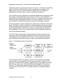
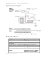
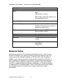
CyberGrasp™ System v2.0
_________________________________________________________________________________________________
USER GUIDE
CyberGrasp™ User’s Guide
|
Version 2.0, rev E, December 2007
CyberGrasp™ System
User Guide v2.0
CyberGlove Systems LLC
2355 Paragon Drive, Suite D
San Jose, CA 95131
Tel: (408) 451-9463
Fax: (408) 689-4362
[email protected]
© 2009 CyberGlove Systems LLC
2
CyberGrasp™ User’s Guide
|
Version 2.0, rev E, December 2007
© 2009 CyberGlove Systems LLC
3
CyberGrasp™ User’s Guide
|
Version 2.0, rev E, December 2007
Table of Contents
OVERVIEW ..........................................................................................................5
SYSTEM COMPONENTS ........................................................................................5
SYSTEM COMPONENT DIAGRAMS ..........................................................................7
TECHNICAL SPECIFICATIONS ................................................................................7
NETWORK SETUP ................................................................................................8
HARDWARE SETUP ............................................................................................12
1. Connect the CyberGlove to the FCU. ...............................................12
2. Connect the position tracker to the FCU..........................................13
3. Mount the position tracker on the CyberGrasp exoskeleton. ........13
4. Connect the actuator enclosure to the FCU. ...................................13
5. Physically connect the FCU to the network.....................................13
6. Connect the power cord to the FCU. ................................................13
7. OPTIONAL: Connect a monitor to the FCU......................................14
FCU BOOT-UP SEQUENCE .................................................................................17
WEARING THE CYBERGRASP EXOSKELETON .......................................................17
ESTABLISH THE DEVICE CONFIGURATION ............................................................21
CALIBRATE THE CYBERGRASP SYSTEM ..............................................................22
APPENDIX A......................................................................................................23
Controlling the FCU Over the Network.....................................................23
APPENDIX B......................................................................................................23
FCU Software Installation.........................................................................23
Initializing the FCU for Software Installation.............................................24
Installing/Updating the FCU Software Over the Network .........................24
APPENDIX C......................................................................................................25
Maintenance & Troubleshooting...............................................................25
CYBERGRASP LIMITED HARDWARE WARRANTY ....................................28
© 2009 CyberGlove Systems LLC
4
CyberGrasp™ User’s Guide
|
Version 2.0, rev E, December 2007
Overview
Congratulations on purchasing your new CyberGrasp™ haptic-feedback
interface, a force-feedback option for CyberGlove Systems LLC’s CyberGlove®
instrumented glove. With its intuitive “reach in and grab it” paradigm, this novel
device provides a natural way to interface with complex 3D computer-generated
worlds and to control end-effectors in telerobotic applications requiring a high
level of dexterity. Possible applications include CAD, training and simulation,
virtual reality, rapid prototyping, telerobotics, medical training, data visualization,
education, and underwater exploration and salvage operations.
This manual describes how to set up and get your CyberGrasp unit operational.
Refer to the CyberGlove user’s manual for information on using the CyberGlove
and to the VirtualHand® Suite User’s Guide and Programmer’s Guide for
additional software information. The rest of this chapter explains how to set-up
your system and wear the CyberGrasp exoskeleton.
!
WARNING: If equipment is used in a manner not specified in this
manual or by CyberGlove Systems, the protection provided by the
equipment may be impaired.
System Components
The CyberGrasp system includes the following parts:
•
•
•
•
•
•
•
•
•
•
•
CyberGrasp Exoskeleton / Actuator Enclosure (Left hand: CGR2202-L-LF,
Right hand: CGR2202-R-LF)
FCU : Force Controller Unit (01307)
3 Finger Ring Middle Small (IV-RMDA-SA719)
1 Finger Ring Small (IV-RMDA-SA717)
1 Finger Ring Thumb Small (IV-RTHB-SA719)
CyberGrasp Data Cable (HAR708-LF)
Umbilical Cable (IV-RHAR708)
AC Power Cable (Depends on country: CCABLE-IEC-XX)
Tracker adapter kit (IV-GSHP-SA110)
o 2 #6-32 Nylon screws
o 2 #4-40 Nylon screws
o 2 Velcro attachment kits (Polhemus and Ascension)
Setup Disk (CS-CYBERGRASP)
CyberGrasp User Manual
© 2009 CyberGlove Systems LLC
5
CyberGrasp™ User’s Guide
|
Version 2.0, rev E, December 2007
CyberGrasp system components are shown in Figure 1. A 22-sensor CyberGlove
system is the core of the interface, used to measure the joint angles of the
fingers, hand, and wrist. This information is used by the host to display a
graphical hand on the screen or control a telerobotic manipulator.
The CyberGlove glove is attached to an Interface Module that processes the data
and sends it to the CyberGrasp Force Control Unit (FCU). The exoskeleton is
responsible for providing force feedback to the user. It attaches to the back of the
hand and guides force-applying tendons to the user’s fingertips. The tension in
the tendons is controlled by the actuators located in the actuator enclosure.
A third party position tracker measures the position and orientation of the hand in
space. The position tracker is attached to a tracker interface unit that processes
the tracker data and communicates it to the FCU. Polhemus® and Ascension®
electromagnetic position trackers are currently supported and are required for
most applications. They are not included as part of the CyberGrasp option and
must be purchased separately.
The FCU is the interface between the devices worn by the user and the host
computers, which communicate via ethernet. The host computers need only
communicate with the CyberGrasp FCU, which in turn communicates with all
other peripherals (CyberGlove, position tracker, and CyberGrasp actuators).
Figure 1: CyberGrasp System Components
Figure 1
CyberGrasp
System
Components
The front panel of the FCU is shown in Figure 5. The actuator power switch
controls power to the exoskeleton’s motors only and does not affect the FCU
processor. To reset the FCU (reboot), toggle the FCU Power switch on the front
panel. Power to the motors will automatically be disengaged if FCU power is
turned off. The Main Power switch located at the rear of the case (Figure 6)
controls power to the whole FCU, and when turned off, overrides front panel
switches.
© 2009 CyberGlove Systems LLC
6
CyberGrasp™ User’s Guide
|
Version 2.0, rev E, December 2007
System Component Diagrams
Figure 2
CyberGrasp
FCU Circuit
Diagram
Figure 3
CyberGrasp
Circuit
Diagram
Technical Specifications
Performance
Specification
Force
Description
12 N Max Continuous per finger
Environment
For indoor use only. Intended to be used in laboratory/office environment.
Specification
Description
Temperature
+5 to +40 degrees C
Altitude
Up to 2000 m above sea level
Humidity
Max humidity 80% up to 31 degrees C,
decreasing to 50% at 40 degrees C.
© 2009 CyberGlove Systems LLC
7
CyberGrasp™ User’s Guide
|
Version 2.0, rev E, December 2007
Electrical
Specification
Mains
Description
FCU
100-240 VAC, 47-63 Hz
Mains supply voltage fluctuation not to
exceed plus/minus 10%.
Overvoltage Category
II
Protective Earthing
Equipment is Class I Earthed
equipment and must be connected to a
properly grounded mains.
Interface
Ethernet (standard STP Category 5
Ethernet cable required)
Mechanicals
Specification
Workspace
Description
1 meter spherical radius from actuator
module
Weight
0.45 kg (Exoskeleton without
CyberGlove)
20 kg (FCU)
Network Setup
Communication with the FCU is achieved via Ethernet protocol. The FCU must
therefore be added to your network just like any other new network device. The
system comes with a default IP address of 192.168.4.254. If this IP address is
suitable for your network, the device can be powered up without modification. If
this IP address is not suitable for your network, you must follow the procedure in
this section. These configuration steps are only needed: 1) when first installing
your FCU; 2) when changing your network configuration; or 3) when re-installing
or updating the FCU internal software. If some of the network terminology used in
the following sections is not familiar to you, please contact your system
administrator.
© 2009 CyberGlove Systems LLC
8
CyberGrasp™ User’s Guide
!
|
Version 2.0, rev E, December 2007
WARNING: A Microsoft Windows (XP) PC with a 1.44 MB floppy
drive is required for editing the FCU configuration floppy disk.
Four steps are required to configure the network settings for the FCU:
1) Physically connect the FCU to the network and power.
2) Create an FCU initialization floppy disk.
3) Write your network setting information onto the disk using the
netcfg.exe utility. 4) Initialize the FCU using the floppy disk.
You will first initialize the FCU by making minimal hardware connections to the
Ethernet network and to FCU power, as described below. Afterwards, proceed
with hardware setup, page 13, before the final rebooting. Always be sure all
devices are powered off before making or changing cable connections.
1) Physically connect the FCU to the network and to power.
a) Make physical connections for initializing the FCU.
Using a standard STP Category 5 Ethernet cable, connect the FCU to your
network hub. The Ethernet connector is located on the back panel of the FCU
(see Figure 6). The FCU can also be connected directly to the host computer if a
cross-over cable is used.
b) Connect power cords to the FCU.
Make sure the main power switch located on the back of the FCU is in the OFF
position. Connect the AC power cord to the back of the FCU (Figure 6) and then
to the mains. Turn the main power switch to ON position.
c) Power up the FCU.
Depress the FCU power switch on the front of the controller. Wait for it to boot
up. When it is ready, it will emit three beeps. This will take approximately 20 to 30
seconds.
2) Create the FCU initialization floppy.
This process consists of transferring a disk image onto a floppy disk. The disk
image is located in the FCU Installation/CyberForce/RevE directory of the
VirtualHand SDK distribution directory.
1. Load VirtualHand SDK onto a compatible Microsoft Windows computer
© 2009 CyberGlove Systems LLC
9
CyberGrasp™ User’s Guide
|
Version 2.0, rev E, December 2007
2. Put a blank formatted floppy into the floppy drive
3. Open a DOS shell, and change your directory to
FCUInstallation/CyberForce/RevE inside the VirtualHand install directory. To
open a DOS shell, click the Windows Start button on the bottom left corner of
your screen. Go to the Run pull-out and Type Run to get an MS-DOS prompt.
4. Finally, type the line below and follow the instructions:
rawrite -f disc.raw -d a
The floppy drive will be active for approximately 30 - 45 seconds as it writes the
disk.
!
WARNING: Once the disk image has been copied to the floppy disk,
remove it from your drive and label it carefully. Booting your
computer from that floppy disk may result in unrecoverable data loss
as the CyberGrasp software replaces the contents on your main
disk!
3) Record your network configuration settings on the FCU initialization
disk.
The network settings for the FCU are stored on the FCU initialization disk by
running the netcfg.exe utility provided on the disk. The netcfg.exe utility runs in a
Microsoft Windows XP environment.
Before running the utility, you will need to obtain the following information from
your system administrator:
•
•
•
•
•
•
fcu name: a name by which the FCU will be known within your network
network domain: the name of your network domain (if any)
IP address: an IP address that is assigned to the FCU within your network
network gateway: an IP address that refers to the network gateway for the
network segment in which the FCU will be connected
domain name server: an IP address for the computer that serves the domain
names for your network
netmask: an IP mask that is used by the segment in which the FCU will be
connected
On a computer running Microsoft Windows, open a DOS shell (Start > Run),
then type cmd and insert the FCU initialization floppy into drive A. At the DOS
shell prompt, type the following:
cd a:
netcfg
© 2009 CyberGlove Systems LLC
10
CyberGrasp™ User’s Guide
|
Version 2.0, rev E, December 2007
The utility will prompt you with the configuration questions, and present a default
answer (in brackets) for each question. You can either enter a new value, or
press enter to accept the default answer. The FCU comes with its software preinstalled, so at the final question select “network configuration only.” If you need
to perform a full FCU software installation, refer to Appendix B, FCU Software
Installation.
!
WARNING: When the floppy disk has been written, remove it from
drive and label it carefully. Booting your computer with that floppy disk
may result in unrecoverable data loss as the CyberGrasp software
replaces the contents on your main disk!
4) Initialize the FCU.
After you have provided all the network configuration information, the FCU must
be initialized with the floppy. To do so, put the initialization floppy into the FCU
floppy drive and power it on or re-boot it if it is already on. The FCU initialization
will start automatically. When the initialization is complete, the FCU will beep
three times. Take the floppy disk out of the floppy drive.
Power the FCU down and complete the hardware setup as described below. Be
sure all the devices are off while making the connections.
© 2009 CyberGlove Systems LLC
11
CyberGrasp™ User’s Guide
|
Version 2.0, rev E, December 2007
Hardware Setup
!
WARNING: Make sure the CyberGrasp Controller is powered-off
when connecting the various components.
Figure 4
CyberGrasp
Block Diagram
!
WARNING: The FCU can be operated in either vertical or horizontal
positions, but avoid putting anything on top of the enclosure as this
could adversely affect the performance of the device.
1. Connect the CyberGlove to the FCU.
The interconnection details of the sub-systems are shown in Figure 4. All
harnesses and cables are labeled. The FCU communicates with the CyberGlove
and tracker systems via a serial RS-232 link. The CyberGrasp system is
controlled using I/O card on the system bus. The following steps are required to
connect all the devices.
!
NOTE: If you have an older CyberGrasp Force Control Unit, refer to
its original manual for the port layout.
© 2009 CyberGlove Systems LLC
12
CyberGrasp™ User’s Guide
|
Version 2.0, rev E, December 2007
2. Connect the position tracker to the FCU.
The serial cord coming from your Ascension or Polhemus position tracker should
connect to serial port 2 on the FCU (Figure 6). Make sure the tracker is
configured to operate at 115 kbaud by setting the dip switches on the
instrumentation unit. Refer to your tracker’s manual for information on using it.
3. Mount the position tracker on the CyberGrasp
exoskeleton.
The tracker sensor is attached to the CyberGrasp exoskeleton via a mounting
block located on the CyberGrasp backplate, as illustrated in Figure 7. The unit
should be positioned such that the tracker cable runs in the same direction as the
force-applying tendons.
There are two sets of holes on the mounting block. One set is used for the
Polhemus trackers, the other set for Ascension trackers. #6-32 nylon screws are
used to secure the Ascension trackers and smaller #4-40 nylon screws should be
used for Polhemus trackers. Both types of screws are supplied with the
CyberGrasp system. As mentioned previously, a position tracker is required to
use the CyberGrasp unit and must be purchased separately.
4. Connect the actuator enclosure to the FCU.
Connect the black cable that attaches to the actuator enclosure (Figure 8) to the
back of the FCU (Figure 6). The actuator enclosure is the box that contains the
motors that drive the tendons on the CyberGrasp exoskeleton.
5. Physically connect the FCU to the network.
Using a standard STP category 5 Ethernet cable, connect the FCU to your
network hub. The Ethernet connector is located on the back panel of the FCU
(Figure 6). The FCU can also be connected directly to the host computer if the
proper Ethernet cable is used.
6. Connect the power cord to the FCU.
Make sure the main power switch located on the back of the FCU is in the OFF
position. Connect the AC power cord to the back of the FCU (Figure 6).
© 2009 CyberGlove Systems LLC
13
CyberGrasp™ User’s Guide
|
Version 2.0, rev E, December 2007
7. OPTIONAL: Connect a monitor to the FCU.
For debugging purposes, a VGA (or SVGA) monitor can be connected to the
FCU to view error messages, but is not required.
!
WARNING: Refer to the CyberGlove system and position tracker
manuals to obtain more information on how to configure them
properly. Do not attempt to run your CyberGrasp unit before
familiarizing yourself with the peripheral devices!
Figure 5
FCU Front Panel
FCU Reset
FCU
Power Switch
!
CyberGrasp Actuator
Power Indicator
CyberGrasp
Actuator Power
NOTE: The CyberGrasp actuator power indicator light will flash
intermittently upon shut-off as the amplifiers for the motors power
down.
© 2009 CyberGlove Systems LLC
14
CyberGrasp™ User’s Guide
|
Version 2.0, rev E, December 2007
Figure 6
Force Control Unit
Rear Panel Layout
Serial Port
for tracker
Ethernet (Host
Link)
VGA Monitor
(for debugging)
CyberGlove
Serial
CyberGrasp
Data
(HAR708-LF)
Internal
Ethernet (do
NOT use)
Keyboard
Main Power
Switch
External AC
Power
NOTE: At the rear panel of the FCU, as shown above, there are a number of
unused motherboard ports including USB, mouse, parallel, sound, and auxiliary
Ethernet. These additional ports are not to be used during normal operation of
the CyberGrasp system. Only attach devices to the appropriately labeled ports as
documented in this manual.
© 2009 CyberGlove Systems LLC
15
CyberGrasp™ User’s Guide
|
Version 2.0, rev E, December 2007
Figure 7
Mounting
the Position
Tracker
!
NOTE: It is important to use nylon or plastic screws when fixing the
electromagnetic position tracker to the backplate. Metal screws can
distort the magnetic field and could adversely affect the accuracy of
the sensor.
Figure 8
CyberGrasp
Actuator Unit
and
Exoskeleton
CyberGrasp
Actuator Unit
CyberGrasp
Data Cable
(HAR708-LF)
© 2009 CyberGlove Systems LLC
Exoskeleton
16
CyberGrasp™ User’s Guide
|
Version 2.0, rev E, December 2007
FCU Boot-up Sequence
1. Make sure there is no disk in the floppy drive and that the FCU power button
is in the OFF (0) position. The FCU power button is located on the front panel
of the system controller (see Figure 5).
2. Make sure that the CyberGrasp actuator power switch is OFF (out).
3. Put the FCU Main Power switch in the ON (I) position. The switch is located
in the back of the FCU (see Figure 6).
4. Depress the FCU Power switch for few seconds. The switch is located in the
front of the controller (see Figure 5).
5. Wait for the FCU to boot up. When it is ready, it will emit three consecutive
beeps. This will take approximately 20 to 30 seconds.
6. After your software is ready to control the actuators, push the CyberGrasp
actuator power switch on the FCU so that it is ON (in). See Figure 5. Both
switches should be illuminated when on.
Wearing the CyberGrasp Exoskeleton
The user should first put on the CyberGlove (fabric glove) and then follow steps 1
through 8 to properly position the CyberGrasp exoskeleton on the hand:
1. Make sure the tendon cables and the CyberGlove cable are not tangled
before beginning. They should all fall to the right of the arm for a right-handed
system, and to the left of the arm for a left-handed system.
2. Make sure the thumb tendon cable goes over the arm and not under.
© 2009 CyberGlove Systems LLC
17
CyberGrasp™ User’s Guide
|
Version 2.0, rev E, December 2007
Figure 10
CyberGrasp System
Velcro Straps
3. Position the CyberGrasp backplate in the middle of the back of the hand such
that the plate is just behind the abduction sensors (the U-shaped elements rising
from the back of the glove). The plate should rest comfortably on the back of the
hand. All cables should go over the hand towards the little finger.
!
WARNING: Do not place the backplate on top or against, the
abduction sensors! This may result in damage to the sensors and is
not covered under warranty.
© 2009 CyberGlove Systems LLC
18
CyberGrasp™ User’s Guide
|
Version 2.0, rev E, December 2007
Figure 11
CyberGrasp System
Back Plate
4. Tighten both Velcro straps as tightly as possible without making the fit
uncomfortable. At this point, the backplate should be firmly and squarely
positioned on the back of the hand.
Figure 12
Finger Loops
5. Slide all the finger loops onto the corresponding fingers. If they are too tight,
loosen them using the thumbscrew. The force applicator rings should then be slid
© 2009 CyberGlove Systems LLC
19
CyberGrasp™ User’s Guide
|
Version 2.0, rev E, December 2007
onto the fingertips (distal phalanges) midway between the tip of the finger and
the first joint.
Figure 13
Thumbscrews
6. The finger loops can be tightened using the thumbscrews. Position the cam in
the center of the middle phalanx before tightening. Flexing the finger makes it
easy to locate the middle phalanx. The device comes with multiple finger rings. If
the current ring is too small or too large to reliably stay on the fingertip, use the
ring clip to replace it with another one.
Figure 14
Properly
Aligned
Thumb
Assembly
© 2009 CyberGlove Systems LLC
20
CyberGrasp™ User’s Guide
|
Version 2.0, rev E, December 2007
7. The next step is to ensure that the thumb assembly is properly aligned with the
thumb as indicated in the Figure 13. This is achieved with the adjustment screw
shown in Figure 14.
8. When the adjustment screw is loosened, it is possible to slide the thumb
assembly back and forth in the slots. The slots are designed so the orientation of
the assembly does not change as it slides through the slots. When moving the
assembly, hold on to the adjustment screw, not the assembly itself, as it may
bind. Very little torque is required to sufficiently tighten the screw. Excessive
torque may cause damage.
Figure 15
Misaligned
Thumb
Assembly
Loosening the adjustment screw will allow
you to slide the thumb assembly in the
slot so it can be aligned with the thumb.
!
WARNING: Do not place the backplate on top or against, the
abduction sensors! This may result in damage to the sensors and is
not covered under warranty!
Establish the Device Configuration
After all devices have been physically connected, their relationship to each other
needs to be established within the Device Configuration Utility (DCU). The
configuration also includes the unique calibration settings for each user of the
Cyber systems. See the VirtualHand SDK User Guide for complete instructions,
but in summary, establishing device relationships requires that you:
© 2009 CyberGlove Systems LLC
21
CyberGrasp™ User’s Guide
▪
▪
▪
▪
|
Version 2.0, rev E, December 2007
Start the Device Manager and the DCU on your host PC.
Create a new configuration using the DCU’s Configuration menu.
Add the devices that make up the configuration by using the DCU’s Device
menu.
Connect to each device by selecting it in the DCU’s Devices window, then
pulling down Device > Connect.
Figure 9
Device Configuration
Utility
Calibrate the CyberGrasp System
Refer to the VirtualHand SDK user guide for complete instructions, but in
summary, calibrating the devices relative to the CyberGrasp system requires that
you:
▪
▪
▪
Select the device you want to calibrate from the device list within the DCU,
then pull down Device > Calibrate.
Follow the onscreen instructions, which require you to move your hand and
fingers in specific ways.
Save the calibration.
© 2009 CyberGlove Systems LLC
22
CyberGrasp™ User’s Guide
|
Version 2.0, rev E, December 2007
Appendix A
Controlling the FCU Over the Network
The FCU can be controlled and monitored over the network for maximum
flexibility. The FCUInstallation/CyberForce/RevE directory of the
distribution CD contains a shell-based utility called nc that will let you
perform remote management. To use it, you must go to the appropriate
directory, and type:
nc numeric_ip_address_of_force 24
The following menu will appear on the screen:
=========================================================
a. restart the device manager
b. restart the device manager and watch its output
c. reboot the grasp controller
d. shutdown the grasp controller
q. quit
=========================================================
Type your choice and hit <enter>. You can choose any above menu items
by type its leading character and hit the enter key.
Appendix B
FCU Software Installation
The Force Control Unit (FCU) comes with Device Manager and all other
associated software pre-installed at the factory. In normal situations, it
must only be given a network name and address so that it can operate
over an Ethernet and a TCP/IP network. This procedure is explained in
Network Setup.
If for any reason the FCU software should become damaged, the
VirtualHand SDK CD contains all necessary files for initializing and
configuring the FCU. Re-installing the software is done in two steps. First,
you must initialize the FCU as described in the Network Setup section and
with the modifications below. Then you must download the FCU software
over the network.
© 2009 CyberGlove Systems LLC
23
CyberGrasp™ User’s Guide
!
|
Version 2.0, rev E, December 2007
WARNING: Reinstalling the FCU software is not required on new
units! Only refer to this section if upgrading the FCU software or
reinstalling it to replace lost/damaged files.
Initializing the FCU for Software Installation
Follow the instructions under 2) Create the FCU Initialization Floppy
section to create the disk. Then follow the instructions in the 3) Record
your network configuration settings on the FCU initialization disk section,
but instead of selecting “network configuration only,” select “full FCU
software installation” in response to the last question.
!
WARNING: Once the disk image has been copied to the floppy disk,
remove it from your disk drive and label it carefully. Booting your
computer with that floppy disk may result in unrecoverable data loss
as the CyberGrasp software automatically replaces the contents on
your main disk!
Next, follow the instructions in the 4) Initialize the FCU section. Once the
initial installation has succeeded, instead of beeping three times (as
happens if you are only configuring the network settings), the FCU will
beep once every 10 seconds to indicate that it is awaiting the rest of the
Device Manager software to be installed over the network.
Installing/Updating the FCU Software Over the Network
Note: These instructions apply to the hardware revision E of the
CyberGrasp system. If you purchased your CyberGrasp system before
January 2007, please contact [email protected] for modified
instructions.
This process consists of transferring the software packages from your
workstation to the FCU using the network link. The software packages are
contained in three archives, located in the
FCUInstallation/CyberForce/RevE directory of the VirtualHand SDK
installation directory.
From a DOS command prompt , go to the appropriate directory, and type:
update_FCU.bat numeric_ip_address_of_force main.tgz
update_FCU.bat numeric_ip_address_of_force stg_update.tgz
© 2009 CyberGlove Systems LLC
24
CyberGrasp™ User’s Guide
|
Version 2.0, rev E, December 2007
The numeric_ip_address_of_force is the number you provided at the
configuration stage of the initialization floppy disk.
Depending on your network capacity and traffic, the data transfer will take
from one to ten seconds. The FCU will beep three times after the software
packages have successfully been installed.
You will then re-boot your FCU. Upon re-boot, a Device Manager is started
automatically and is ready to handle client requests. You can use either the
Device Configuration Utility or the demo applications supplied in the
distribution CD to ensure that the system is working properly. Please refer to
the VirtualHand SDK User’s Guide for instructions on how to do so.
Appendix C
Maintenance & Troubleshooting
Maintenance
CyberGrasp is factory serviceable only, containing no user serviceable
parts. The surfaces of the FCU may be cleaned with mild detergent using
a slightly damp cloth.
Troubleshooting
If you are experiencing problems with your CyberGrasp unit, please read
the following list of problems carefully. If you are still unable to solve your
problem, you can contact CyberGlove Systems LLC support staff at
[email protected]
PROBLEM: Cannot hear the three beeps after the floppy drive light goes
off.
SOLUTION: This is most likely caused by a defective boot floppy. Try to
make another boot floppy, preferably using a new diskette, and boot the
FCU with it. If it still fails, try to make the floppy on another machine. DO
NOT USE THE FCU INITIALIZATION FLOPPY TO BOOT YOUR PC.
BOOTING YOUR COMPUTER WITH THIS DISK MAY RESULT IN
UNRECOVERABLE DATA LOSS AS THE CYBERGRASP SOFTWARE
REPLACES THE CONTENTS ON YOUR MAIN DISK!
© 2009 CyberGlove Systems LLC
25
CyberGrasp™ User’s Guide
|
Version 2.0, rev E, December 2007
PROBLEM: The update_FCU.bat on XP prompts “Failed to connect to the
CyberGrasp.”
SOLUTION: The message indicates that the installation program cannot
establish a stable connection to the FCU. The following should be
checked:
•
Make sure the network setting for the FCU is configured properly, and has
access to your LAN. Any typographic error in the information you provided
when running netcfg.exe will likely cause the FCU network interface to be
configured incorrectly. Examine the settings by running netcfg.exe on the
boot floppy again. Contact your network administrator if you are not sure
about the settings.
•
Make sure the host computer can access the FCU over the network. This
can be verified by using the ping command and “pinging” the FCU from
the host machine as:
ping grasp_ip.
•
Only one update session is allowed to run at any time. Attempts to start
the update process will be denied if there is another update session
running. If you aborted an update; please wait for at least 10 seconds
before another attempt.
PROBLEM: Could not hear the three beeps after the installation program
finished on the host computer.
SOLUTION: Your network may be experiencing heavy traffic at the
moment you run the update program. Therefore it may time-out before it
finishes the update. Try to run the update program a few more times. Also,
the beeps may be too weak to hear if you are at a distance from the FCU.
Verify whether the Device Manager is running with the Device Control
Utility. You can also use the nc program to restart the Device Manager or
reboot the FCU manually.
PROBLEM: The FCU beeps continuously after it is booted with the
Installation floppy.
SOLUTION: The beeps are normally an indication of a serious hardware
problem. Please contact CyberGlove Systems technical support for further
assistance.
© 2009 CyberGlove Systems LLC
26
CyberGrasp™ User’s Guide
|
Version 2.0, rev E, December 2007
PROBLEM: The software installation finished successfully, but I could not
access the FCU with the nc utility.
SOLUTION: Reboot the FCU.
© 2009 CyberGlove Systems LLC
27
CyberGrasp™ User’s Guide
|
Version 2.0, rev E, December 2007
CYBERGRASP LIMITED HARDWARE
WARRANTY
PLEASE READ THIS DOCUMENT CAREFULLY! IT CONTAINS VERY
IMPORTANT INFORMATION ABOUT CUSTOMER RIGHTS AND OBLIGATIONS,
AS WELL AS LIMITATIONS AND EXCLUSIONS THAT MAY APPLY TO THIS
LIMITED WARRANTY.
TERM: The term of this warranty (“Warranty Period”) is one (1) year from the date of
delivery of the CyberGrasp Product (“Product”) only to the initial end user purchaser
(“Customer”) located anywhere in the world, except a member state of the European
Union. For end user purchasers located in a member state of the European Union
only, the term of this warranty (“Warranty Period”) is two (2) years from the date of
delivery of the Product only to the initial end user purchaser (“Customer”).
LIMITED WARRANTY REPAIRS: During the Warranty Period, CyberGlove Systems
agrees to repair or replace the Customer’s Product if such Product does not perform
substantially in accordance with CyberGlove Systems’ then-current, published
functional specifications for the Product at the date of the Product’s manufacture.
To request warranty service, Customer must contact CyberGlove Systems'
Customer Technical Support within the applicable Warranty Period. Customer
agrees to provide CyberGlove Systems the following information: (i) Product model;
(ii) Product serial number; (iii) description of problem or reason for coverage; and (iv)
such other information as CyberGlove Systems may request. If CyberGlove Systems
determines service is required and covered by this warranty, CyberGlove Systems
will issue a Return Material Authorization (“RMA”) Number and return instructions.
Once Customer has received an RMA number, Customer must ship the Product to
CyberGlove Systems (or another location specified by CyberGlove Systems) in its
original or equivalent packaging and in accordance with CyberGlove Systems’ return
instructions, include the RMA number, prepay shipping charges, and insure the
shipment or accept the risk of loss or damage during shipment.
CyberGlove Systems will ship the repaired or replacement Product to Customer
freight prepaid (Incoterms 2000 - Delivery Duty Unpaid), if the repair or replacement
is covered by this warranty. CyberGlove Systems assumes no responsibility for
freight and all other taxes and charges for non-warranty repairs or replacement
(Incoterms 2000 - ExWorks).
CyberGlove Systems owns all parts removed from repaired Products. CyberGlove
Systems uses new and reconditioned parts made by CyberGlove Systems and/or
various manufacturers in performing limited warranty repairs and building
replacement Products. If CyberGlove Systems repairs or replaces a Product, the
Warranty Period is not extended.
© 2009 CyberGlove Systems LLC
28
CyberGrasp™ User’s Guide
|
Version 2.0, rev E, December 2007
EXCLUSIONS: This warranty does not apply to Products that CyberGlove Systems
determines, upon inspection, have become defective, damaged, or nonconforming
due to external causes, including accident, abuse, mishandling, misuse, alteration,
negligence, normal wear and tear, improper installation by a party other than
CyberGlove Systems, problems with electrical power, use which is not in accordance
with the information and precautions described in the applicable end user manual
and/or documentation, service by a party other than CyberGlove Systems, failure to
perform required preventive maintenance, problems caused by use of parts or
components not supplied by CyberGlove Systems, operation or storage of the
Product in a temperature or environment outside of those specified, damage during
shipment, or other causes beyond CyberGlove Systems' control. This warranty does
not apply to (i) any third party products, software, or components not manufactured
by CyberGlove Systems or (ii) any third party products sold by CyberGlove Systems
for use with the Product.
THIS WARRANTY IS PROVIDED IN LIEU OF ALL OTHER RIGHTS, CONDITIONS
AND WARRANTIES. CYBERGLOVE SYSTEMS MAKES NO OTHER EXPRESS
OR IMPLIED WARRANTY WITH RESPECT TO THE SOFTWARE, HARDWARE,
PRODUCTS, DOCUMENTATION, OR CYBERGLOVE SYSTEMS SUPPORT,
INCLUDING, WITHOUT LIMITATION, ANY WARRANTY OF MERCHANTABILITY,
FITNESS FOR A PARTICULAR PURPOSE, THOSE ARISING FROM A COURSE
OF DEALING, USAGE, OR TRADE PRACTICE AND NON-INFRINGEMENT.
CYBERGLOVE SYSTEMS DOES NOT WARRANT THAT ANY PRODUCTS WILL
BE ERROR-FREE, OR THAT ANY DEFECTS THAT MAY EXIST IN ITS
PRODUCTS CAN BE CORRECTED. IN NO EVENT SHALL CYBERGLOVE
SYSTEMS BE LIABLE FOR COST OF PROCUREMENT OF SUBSTITUTE
GOODS, LOST PROFITS OR ANY OTHER SPECIAL, INDIRECT,
CONSEQUENTIAL, OR INCIDENTAL DAMAGES (INCLUDING BUT NOT LIMITED
TO LOST DATA), HOWEVER CAUSED WHETHER OR NOT CYBERGLOVE
SYSTEMS HAS BEEN ADVISED OF THE POSSIBILITY OF SUCH DAMAGES.
NO RESELLER IS AUTHORIZED TO MAKE ANY MODIFICATIONS,
EXTENSIONS, OR ADDITION TO THIS WARRANTY.
THE WARRANTIES EXPRESSLY SET FORTH IN THIS LIMITED WARRANTY
STATEMENT ARE LIMITED IN DURATION TO THE LIMITED WARRANTY
PERIOD SET FORTH ABOVE AND NO WARRANTIES, WHETHER EXPRESS OR
IMPLIED, WILL APPLY AFTER SUCH PERIOD.
Some jurisdictions do not allow the exclusion or limitation of incidental or
consequential damages, so the above exclusion or limitation may not apply.
Additionally, some jurisdictions do not allow the exclusion of certain implied
warranties or conditions or limitations as to the term of warranty or condition.
Therefore the foregoing disclaimers may not apply in the jurisdiction of Customer’s
purchase.
© 2009 CyberGlove Systems LLC
29
CyberGrasp™ User’s Guide
|
Version 2.0, rev E, December 2007
The CyberGrasp system was partially developed with funding from the Office of
Naval Research’s STTR program (contract #N00014-97-C-0112).
This equipment has been tested and found to comply with the limits for a Class A
digital device, pursuant to part 15 of the FCC Rules. These limits are designed to
provide reasonable protection against harmful interference when the equipment
is operated in a commercial environment. This equipment generates, uses, and
can radiate radio frequency energy and, if not installed and used in accordance
with the instructions, may cause harmful interference to radio communications.
Operation of this equipment in a residential area is likely to cause harmful
interference, in which case the user will be required to correct the interference at
personal expense.
CyberGlove Systems LLC
2355 Paragon Drive, Suite D
San Jose, CA 95131
Tel: (408) 451-9463
Fax: (408) 689-4362
[email protected]
This document does not create any express or implied warranty about CyberGlove Systems or
about its products or services. CyberGlove Systems has made reasonable efforts to verify that
the information contained herein is accurate, but CyberGlove Systems assumes no responsibility
for its use. All information is provided "as-is." The product specifications and features described in
this publication are based on the latest information available; however, specifications are subject
to change without notice, and certain features may not be available upon initial product release.
Contact CyberGlove Systems for current information regarding its products or services.
CyberGlove Systems’ products and services are subject to CyberGlove Systems’ standard terms
and conditions.
©2009 CyberGlove Systems LLC. All rights reserved. CyberGlove Systems, the CyberGlove
Systems logo, CyberForce, CyberGlove, CyberGrasp, and VirtualHand are trademarks of
CyberGlove Systems LLC in the U.S. and other countries. All other trademarks are the property
of their respective owners. CyberForce is produced under license from SensAble Technologies,
Inc.
Doc P/N M01011, rev A, 12/07
© 2009 CyberGlove Systems LLC
30