1
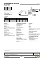
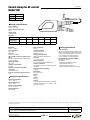
CLAMPS
C
hauvin Arnoux has been designing,
developing and manufacturing measurement
instruments for over one hundred years now.
As the inventor of the current clamp in 1934,
Chauvin Arnoux masters the principles
of current capture and measurement to perfection.
Backed by its in-depth knowledge of practical
professional requirements, Chauvin Arnoux is able
to provide users with:
n A large number of digital display models for the
measurement of harmonics, power and earths, ...
n Together with a large number of special
products, developed for customers, or personalised
to their specifications.
By combining innovation with technological
expertise, Chauvin Arnoux manufactures products
with a reputation for quality that comply with
international standards.
Chauvin Arnoux,
world leader in current clamps.
the Current
catalogue
Clamps
“ accessories ”
and flexible probes
Theoretical overview.......................................... i.1
Selection guides
AC.............................................................................i.2
AC/DC.......................................................................i.3
Leakage / Scope / Process / CT output.......................i.4
AC current clamps and flexible probes
MINI series..........................................................1.0
● MN series............................................................2.0
● Y series...............................................................3.0
● C series...............................................................4.0
● D series...............................................................5.0
● B series...............................................................6.0
● MiniFLEX series..................................................7.0
● AmpFLEX™ series..............................................8.0
●
AC/DC current clamps
K series...............................................................9.0
● E series.............................................................10.0
● PAC series.........................................................11.0
●
Accessories ....................................................... 12.0
See last page for details of "made to order" model.
Non-contractual document
Table of contents - Ed 3
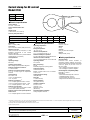
Current clamps
A modern method for measuring electrical currents
Current measurement
Introduction
Clamp are designed to extend
the current measuring capabilities
of DMMs, power instruments,
oscilloscopes, hand-held scopes,
recorders or loggers, and other
diverse instruments.
The clamp is placed around the
current-carrying conductor to perform
non-contact current measurements
without interrupting the circuit under
test. The clamp outputs current or
voltage signals directly proportional
to the measured current, thereby
providing current measuring and
displaying capabilities to instruments
with low current or voltage inputs.
Non-contractual document
906111964 - Ed 3
When making a measurement, the
current-carrying conductor circuit is
not broken and remains electrically
isolated from the instrument's input
terminals. As a result, the instrument’s
low input terminal may be either
floated or earthed. It is not necessary
to interrupt the power supply when
using a current clamp for taking
measurements, so costly downtime
can be eliminated.
True RMS measurements within the
clamp's frequency response are possible by using most Chauvin Arnoux
current clamps with a true RMS
multimeter.
i.1 (1/4)
In most cases, RMS measurements
are not limited by the clamps, but
by the instrument to which they are
connected. Best results are provided
by clamps offering inherent high
accuracy, good frequency response,
and minimal phase shift.
Several Chauvin Arnoux clamps are
patented for their unique circuitry and
design.
Current clamps
Current measurement
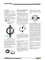
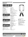
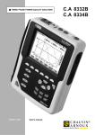
A transformer (figure 1) is essentially
two coils wound on a common iron
core. A current I1 is applied through
the coil C1, inducing through the common core a current I2 in the coil C2.
The number of turns of each coil and
the current are related by:
N1 x I1 = N2 x I2
I2
Récepteur
Receptor
Production
Conducteur
Câble
current
I1
▼
▼
I2
B1 (N1)
B2 (N2)
Z
Circuit
magnétique
Iron
core
Figure 1
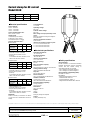
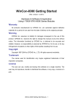
This same principle is applied to a
current clamp (figure 2). The articulated magnetic core holds the coil B2
and clamps onto a conductor where
the current I1 is flowing.
B1 is simply the conductor where the
user is measuring the current with the
number of turns N1 equal to one. The
current sensor clamped around the
conductor provides an output proportional to the number of turns in its coil
B2, such that:
I2 (clamp output) = N1/N2 x I1 where
N1 = 1 or clamp output = I1/N2 (number
of turns in the clamp's coil).
906111964 - Ed 3
mA ou A
mA
or A le
suivant
range
on your
calibre
de
instrument
l'appareil
Figure 2
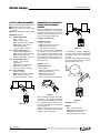
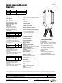
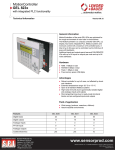
Current clamps may be used with
other instruments with current ranges,
provided that these instruments have
the required input impedance (see
figure 3).
A
I
AC
If N2 equals 1000, then the clamp has
a ratio of N1/N2 or 1/1000, which is
expressed as 1000:1. Another way
to express this ratio is to say that the
clamp output is 1 mA/A - the clamp
output is 1 mA (I2) for 1 A (or 1 A @
1000 A) flowing in the jaw window.
There are numerous other ratios
possible : 500:5, 2000:2, 3000:1,
3000:5, etc. for different applications.
Figure 3
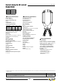
Current clamps may also have AC or
DC voltage outputs to accommodate
current measurements with instru
ments (loggers, scopes, etc.) with voltage ranges only (figures 4 and 5).
R
I
V
AC
The most common application is the
use of a current clamp with a digital
multimeter. Take as an example a
current clamp with a ratio of 1000:1
(model C100) with an output of
1 mA/A. This ratio means that any
current flowing through the probe
jaws will result in a current flowing at
the output:
Conductor input
Clamp ouput
1000 A
750 A
250 A
10 A
1A
750 mA
250 mA
10 mA
Non-contractual document
A
B2 (N2)
Mâchoires
Probes jaws
where N1 and N2 are the number of
turns in each coil.
From this relationship:
I2 = N1 x I1/N2 ou I1 = N2 x I2/N1.
Conductor/cable
Conducteur/Câble
I1
i.1 (2/4)
Figure 4
▼
An AC current clamp may be viewed
as a variant of a simple current
transformer.
The clamp output is connected to
a DMM set on the AC current range
to handle the clamp output. Then, to
determine the current in the conductor, multiply the reading of the DMM
by the ratio (e.g., 150 mA read on
the 200 mA DMM range represents
150 mA x 1000 = 150 A in the conductor measured).
▼
Theory of Operation:
It is often difficult to measure I1
directly because of currents which
are too high to be fed directly into
a meter or simply because breaking into the circuit is not possible. To
provide a manageable output level,
a known number of turns is made on
the clamp's coil.
▼
AC CURRENT CLAMPS
I
V
DC
Figure 5
This is simply done by conditioning
the current clamp output inside the
clamp to provide voltage (e.g., model
Y4N or MINI09). In these cases, the
probe mV output is proportional to
the measured current.
Current clamps
Current measurement
Theory of Operation (Hall effect)
Unlike on traditional AC transformers,
AC/DC current measurement is often
achieved by measuring the strength
of a magnetic field created by a current-carrying conductor in a semi
conductor chip using the Hall-effect
principle.
When a thin semiconductor (figure 6)
is placed at right angles to a magnetic
field (B), and a current (Id) is applied to
it, a voltage (Vh) is developed across
the semiconductor. This voltage is
known as the Hall voltage, named
after the US scientist Edwin Hall who
first reported the phenomenon.
Id
i
u
Vh
r
B
Figure 6
When the Hall device drive current
(Id) is held constant, the magnetic
field (B) is directly proportional to the
current in a conductor. Thus, the Hall
output voltage (Vh) is representative
of that current.
n = turns with
cross-section S
Rogowski coil
This AC voltage u is then passed via
a screened cable to the casing containing all the processing electronics
and the battery power supply.
Because there are not magnetic circuits on these sensors, they are very
lightweight and flexible. Without magnetic circuits, there is no saturation
effect or overheating.
This feature offers ensures excellent
linearity and low phase shift.
+
V1 = k dI
dt
-
Such an arrangement has two
important benefits for universal
current measurement.
First, since the Hall voltage is not
dependent on a reversing magnetic field, but only on its strength,
the device can be used for DC
measurement.
Second, when the magnetic field
strength varies due to varying current
flow in the conductor, response to
change is instantaneous. Thus, complex AC wave forms may be detected
and measured with high accuracy and
low phase shift
V2 = kI
I
Figure 14-10 : Principe de la bobine de Rogowski
Non-contractual document
906111964 - Ed 3
i.1 (3/4)
Iron core
→
The AmpFLEX™ and MiniFLEX sensors are based on the principle of the
Rogowski coil.
The primary circuit is constituted by
the conductor carrying the alternating current to be measured, while the
secondary is formed by a special coil
wound on a flexible support.
At its terminals, this coil develops a
voltage proportional to the derivative
of the primary current to be measured:
µ .n
di
u = 0 x S.
2π.r
dt
where µ0 = vacuum permeability
S = surface area of a turn
n = number of turns
r = core radius
The basic construction of a clamp jaw
assembly is shown in figure 7, (note:
one or two Hall generators are used
depending on the type of current
clamp).
→
AC/DC CLAMP-ON CURRENT PROBES
OPERATING PRINCIPLE
Air gap
Hall
generator
Conductor
Figure 7
The Chauvin Arnoux AC/DC current
clamps were developed using the
above principle, together with patented
electronic circuitry incorporating signal
conditioning for linear output and a
temperature compensation network.
These have a wide dynamic range
and frequency response with highly
accurate linear output, for application in all areas of current measurement up to 1,500 A. Direct currents
can be measured without the need of
expensive, power-consuming shunts,
and alternating currents up to several
kHz can be measured accurately to
respond to the requirements of complex signals and RMS measurements.
The clamp outputs are in mV (mV
DC when measuring DC, and mV AC
when measuring AC) and may be
connected to most instruments with
a voltage input, such as DMMs, loggers, oscilloscopes, handheld scopes,
recorders, etc.
Chauvin Arnoux also offers various
technologies for DC measurements,
as in the K1 and K2, designed to
measure very low DC currents and
using saturated magnetic circuit
technology.
The AC/DC clamps also offer the
opportunity to display or measure
True RMS in AC or AC+DC.
Current clamps
Examples (figure 8):
AC:
clamp model: Y2N
Ratio : 1000:1
Output: 1 mA AC/A AC
DMM: set to 200 mA AC range
DMM reading: 125 mA AC
Current in conductor :
125 mA x 1000 = 125 A AC
DC : clamp model: PAC 21
1 mV DC/A DC (Hall sensor)
DMM: set to 200 mV DC range
DMM reading: 160 mV DC Current in conductor: 160 A DC
AC : clamp model: PAC 11
Output : 1 mV AC/A AC
(Hall sensor) DMM: set to 200 mV AC range
DMM reading: 120 mV AC Current in conductor: 120 A AC
DC : micro clamp K1
Output: 1 mV/mA DMM: set to 200 mV DC range
DMM reading: 7.4 mV DC Current in conductor: 7.4 mA
Power
source
Power
source
▼
I
IL
Load
▼
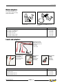
■Connect the clamp to the instrument
■Select the function and range
■Clamp the clamp around a single
conductor
■Read the conductor’s current value
MEASUREMENTS OF LOW CURRENTS,
PROCESS LOOPS AND LEAKAGE
CURRENTS
Numerous clamps are offered for low
current measurements. For example,
models K1 and K2 have a 50 mA DC
sensitivity and the model K2 may be
used on 4-20 mA process loops.
▼
AC OR DC CURRENT MEASUREMENT
Current measurement
I+IL
Example: 4-20 mA loop
Clamp model: K2
Output: 10 mV/mA
DMM: set to 200 mV DC range DMM reading: 135 mV DC Loop current: 13.5 mA DC
When the current to be measured is
too low for the clamp or better accuracy is required, it is possible to insert
the conductor multiple times through
the probe jaws. The value of the current is the ratio of the reading to the
number of turns.
Example: figure 9
Clamp model: C100
Ratio: 1000:1
DMM: set to 200 mA AC range
Turns in clamp jaw: 10
DMM reading: 60 mA AC
Current in conductor:
60 mA x 1,000 / 10 = 6,000 mA = 6 A
Figure 10
To measure low currents or leakage,
you need a clamp which will measure
low values, such as the model B102
or C173.
However, earth leakage currents may
also be measured directly with the
simple model (figure 11).
Motor
IL
Load
Figure 9
Figure 8
Non-contractual document
906111964 - Ed 3
When the clamp is placed around two
conductors with different polarities,
the resulting reading will be the difference between the two currents. If the
currents are the same, the reading will
be zero (figure 10).
When a reading other than zero is
obtained, the reading is the amount of
leakage current on the load.
i.1 (4/4)
Figure 11
Example: figure 11
MINI 05
Ratio: 1 mV AC/mA AC
DMM: set to 200 mA AC range
DMM reading: 10 mV AC
Leakage current: 10 mA AC
Most clamps perform with greater accuracy at the upper end of their range. Several clamps are designed to measure very
low DC or AC.
3- What size conductor will you clamp
onto? This parameter determines the
clamp jaw size needed.
4- What type of clamp output do you
need or can you work with (mA, mV, AC,
DC, etc.)? Check the maximum receiver
impedance to ensure that the clamp will
perform to specifications.
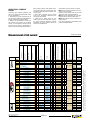
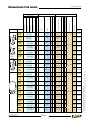
Measurement of AC current
Selection guide
Specific features
MINI 05
Chap. 1
MINI 09
1…100 A
10 V AC
●
0.1 V AC
1…150 A
●
●
0.2 A AC
MN09
0.5…240 A
●
0.2 A AC
MN010
0.5…240 A
●
0.2 A AC
MN011
0.5…240 A
●
0.2 A AC
MN012
0.5…240 A
●
2 V AC
MN013
0.5 A…240 A
●
2 V AC
MN014
0.5 A…240 A
●
0.2 V AC
MN015
0.5 A…240 A
●
0.2 V AC
MN021
0.1 A…240 A
●
MN023
0.1 A…240 A
●
MN060
MN071
MN073
MN088
0.1 A…24 A
0.5 A…240 A
0.1 A…24 A
0.5 A…240 A
0.1 A…60 A peak
0.5 A…600 A peak
10 mA…12 A
10 mA…2,4 A
100 mA…240 A
15 V DC
●
●
●
●
●
2 V AC
2 V AC
1 V AC
2 V AC
●
2 V AC
Automatic DC voltage
≤ 1 %
P01120402
1000/1
●
≤ 2 %
P01120403
1000/1
●
≤ 2 %
P01120404
1 A / 10 mV
≤ 1 %
P01120405
1 A / 10 mV
≤ 1 %
P01120406
1 A / 1 mV
≤ 1 %
P01120416
40 Hz…10 kHz
●
1 A / 10 mV
1 A / 100 mV
1 A / 10 mV
●
2 V AC
●
P01120401
1000/1
1 A / 10 mV
2 V AC
●
●
P01105105Z
P01105109Z
1 A / 100 mV
●
≤ 2 %
≤ 4 %
1000/1
●
≤ 3 %
≤ 1 %
●
2 V AC
P01105102Z
P01105103Z
1000/1
1 A / 1 mV
●
≤ 1 %
≤ 2 %
1 A / 100 mV
●
2 V AC
●
BNC connector (coaxial)
●
48 Hz… 500 Hz ≤ 2.5 % P01105101Z
● 48 Hz… 10 kHz
48 Hz… 500 Hz
1 A / 1 mV
●
2 V AC
●
1 mA / 1 mV
●
●
0.2 A AC
●
Ø 4 mm female sockets
1 A / 1 mV
0.1 V AC
●
Lead + Ø 4 mm safety connectors(3)
●
Voltage
●
Current
●
1000/1
DC
1000/1
●
AC
Strong current
●
0.15 A AC
0.5…240 A
MN039
Chap. 3
5 mA…10 A
0.15 A AC
MN08
MN038
Chap. 2
1…100 A
●
●
To
order
1 A / 100 mV
40 Hz…40 kHz
1 A / 10 mV
≤ 1 %
P01120417
≤ 2 %
P01120418
≤ 1.5 %
P01120419
≤ 1 %
P01120407
≤ 1 %
P01120408
≤ 2 %
≤ 1.5 %
1 A / 100 mV
≤ 1 %
1 mA / 1 mV
≤ 1 %
40 Hz…10 kHz
1 A / 10 mV
≤ 2 %
P01120409
P01120420
P01120421
1 A / 100 mV
≤ 2 %
P01120410
1 A / 100 mV
≤ 2 %
P01120415
0.5 A…240 A
●
20 V DC (2)
MN089
0.5 A…240 A
●
20 V DC (2)
Y1N
4 A…600 A
●
0.5 A AC
●
1000/1
●
≤ 3 %
P01120001A
Y2N
4 A…600 A
●
0.5 A AC
●
1000/1
●
≤ 1 %
P01120028A
Y3N
4 A…600 A
●
5 A AC
●
100/1
Y4N
4 A…600 A
●
0.5 V DC (2)
●
500 A / 0.5 V
Y7N
1 A…1200 A peak
●
1 V AC
Non-contractual document
906111964 - Ed 3
i.2 (1/3)
●
●
●
1 A / 1 mV
48 Hz…1 kHz
5 Hz…10 kHz
≤ 3 %
P01120029A
≤ 1 %
P01120005A
≤ 2 %
P01120075
(3) Lead + electronic unit with Ø 4 mm safety connectors, centre distance 19 mm, for K and AmpFLEX™ series
MINI 03
Output protected against voltage surges
2…150 A
50 mA…100 A
Transformation ratio (input/output)
MINI 01
MINI 02
Medium current
Weak current
Model
Very weak current
Series
Bandwidth (frequency in Hz)
Output - Connections
Measurement of power (slight phase shift)
Input
Measuring range (1)
(1) The upper value corresponds to 120 % of the maximum rated value (2) Reformatting of AC signal by diodes
Answering the following questions will
help you to select the appropriate clamp
for your applications:
1- Determine if you are measuring AC or
DC (DC current clamps are categorized as
AC/DC because they measure both).
2- What is the the maximum current you
will measure, and what is the minimum
current you will measure? Check that the
accuracy at low levels is appropriate, or
select a low-current measurement clamp.
Other factors you may want to consider:
■ What is the working voltage of the conductor to be measured ?
Chauvin Arnoux clamps must not be used
above 600 volts (see specifications).
■ What type of termination do you need:
sockets, banana leads or BNC leads ?
■ Will the probe be used for harmonics or
power clamp ?
Look at the frequency specifications and
phase shift specifications.
Typical accuracy
SELECTING A CURRENT
PROBE
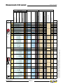
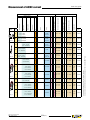
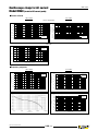
Measurement of AC current
Selection guide
Automatic DC voltage
●
1 A AC
●
1000/1
≤ 0.5 %
P01120301
0.1 A…1200 A
●
1 A AC
●
1000/1
●
≤ 0.5 %
P01120302
C103
0.1 A…1200 A
●
1 A AC
1000/1
●
≤ 0.5 %
P01120303
C106
0.1 A…1200 A
●
1 V AC
1 A / 1 mV
≤ 0.5 %
P01120304
C107
0.1 A…1200 A
●
1 V AC
1 A / 1 mV
≤ 0.5 %
P01120305
C112
1 mA…1200 A
●
1 A AC
≤ 0.3 %
P01120314
C113
1 mA…1200 A
●
1 A AC
C116
1 mA…1200 A
●
C117
1 mA…1200 A
●
C122
1 A…1200 A
●
5 A AC
●
●
5 A AC
●
●
●
1000/1
●
●
1000/1
●
●
≤ 0.3 %
P01120315
●
1 A / 1 mV
●
≤ 0.3 %
P01120316
●
≤ 0.3 %
P01120317
≤ 1 %
P01120306
●
1 V AC
1 V AC
1 A…600 A
1 A / 1 mV
●
1000/5
500/5
3 V peak
≤ 3 %
10 Hz …100 kHz ≤ 2 %
1000 A / 1 V
≤ 1 %
1 mA…1.2A
1A/1V
≤ 0.7 %
0,01 A…12 A
10 A / 1 V
0.1 A…120 A
●
2 V peak
1 V AC
●
●
1 A…3600 A
●
1 A AC
1 A…3600 A
●
1 A AC
●
1 A AC
●
●
1 A…600 A
1 A…1200 A
1 A…3600 A
D35N
1 A AC
2000/1
●
5 A AC
30 Hz…1 kHz
≤ 0.5 %
30 Hz…5 kHz
≤ 1 %
●
1 A…3600 A
●
3 A AC
●
1 A…360 A
1 A…900 A peak
30 A/3 V
●
3 V AC
300 A/3 V
●
500 µA…4 A
P01120053A
≤ 1 %
≤ 0.5 % P01120054A
●
3000/5
≤ 0.5 %
●
≤ 0.5 % P01120055A
●
30 Hz…5 kHz
≤ 2 %
P01120056A
≤ 2 %
P01120057A
3000 A/3 V
1 A / 10 mV
●
1 V AC
●
1 A…9000 A peak
0.5 A…400 A
30 Hz…1.5 kHz
2000/5
3000/3
P01120052A
≤ 3 %
1000/5
5 A AC
P01120050A
≤ 0.5 % P01120051A
1 A…1200 A
1 A…90 A peak
906111964 - Ed 3
●
≤ 1 %
●
P01120064
≤ 1 %
●
≤ 0.5 %
1 A…3600 A
Non-contractual document
≤ 1 %
1500/5
●
0.1 A…36 A
B102
≤ 0.5 %
1000/5
1 A…2400 A
5 A AC
≤ 0.5 % P01120049A
≤ 0.5 %
500/5
●
P01120309
≤ 3 %
30 Hz…1.5 kHz
●
3000/5
●
1 A…3600 A
D38N
30 Hz…5 kHz
3000/1
●
≤ 0.3 %
1 A…1800 A
D36N
D37N
●
1000/1
●
1 A…600 A
1 A…1200 A
●
●
1500/1
1 A…3600 A
D33N
●
3000/1
500/1
1 A…1200 A
≤ 0.5 %
P01120308
≤ 0.2 %
3000/1
1000/1
●
1 A…1800 A
1 A…2400 A
10 Hz…3 kHz
100 A / 1 V
1000 A / 1 V
D30N
P01120307
≤ 1 %
10 A / 1 V
3 V peak
●
D30CN
D34N
≤ 1 %
100 A / 1 V
0.1 A…300 A peak
1 A…1200 A
D32N
≤ 2 %
48 Hz…1 kHz
●
1000/5
1 A…2000 A peak
D31N
●
250/5
0.1 A…30 A peak
C173
30 Hz…10 kHz
●
1 A / 1 mV
30 Hz…50 kHz
1 A / 0.1 mV
●
4 V AC
0.4 V AC
i.2 (2/3)
●
1 mA / 1 mV
1 A / 1 mV
10 Hz…1 kHz
≤ 0.5 %
≤ 0.35 %
P01120083
(3) Lead + electronic unit with Ø 4 mm safety connectors, centre distance 19 mm, for K and AmpFLEX™ series
●
(1) The upper value corresponds to 120 % of the maximum rated value
C148
C160
Chap. 6
Output protected against voltage surges
0.1 A…1200 A
C102
1 A…1200 A
Chap. 5
To
order
C100
1 A…300 A
Chap. 4
Transformation ratio (input/output)
BNC connector (coaxial)
Ø 4 mm female sockets
Lead + Ø 4 mm safety connectors(3)
Voltage
Current
DC
AC
Strong current
Medium current
Weak current
Model
Very weak current
Series
Typical accuracy
Specific features
Bandwidth (frequency in Hz)
Output - Connections
Measurement of power (slight phase shift)
Input
Measuring range (1)
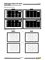
Measurement of AC current
Selection guide
Specific features
Chap. 7
A 100
Chap. 8
0.5 A…3000 A
MA100
300-3000 /3
(35 cm)
0.5 A…3000 A
MA100
300-3000/3
(35 cm)
0.5 A…3000 A
0.5 A…300 A
0.5 A…300 A
MA200
30-300/3
(17 cm)
0.5 A…450 A peak
MA200
30-300/3
(25 cm)
0.5 A…450 A peak
MA200
3000 /3
(35 cm)
A100
20-200/2
(45 cm)
0.5 A…45 A peak
0.5 A…45 A peak
5 A…4500 A peak
0.5 A…20 A
0.5 A…200 A
3 V AC
●
3 V AC
●
3 V AC
●
●
4.5 V peak
●
●
4.5 V peak
●
●
4.5 V peak
●
●
2 V AC
●
100 mV/A
10 mV/A
10 mV/A
●
1 mV/A
●
10 mV/A
1 mV/A
10 mV/A
●
1 mV/A
10 mV/A
1 mV/A
Automatic DC voltage
●
●
Output protected against voltage surges
3 V AC
Transformation ratio (input/output)
●
BNC connector (coaxial)
3 V AC
10 mV/A
●
≤ 1 %
P01120560
●
≤ 1 %
P01120563
●
≤ 1 %
P01120561
●
≤ 1 %
P01120564
●
≤ 1 %
P01120562
●
≤ 1 %
P01120565
5 kHz…20 kHz
100 mV/A
≤ 1 %
10 mV/A
+ 0.3 A
100 mV/A
5 Hz…1 MHz
10 mV/A
≤ 1 %
1 mV/A
1 A / 100 mV
1 A / 10 mV
≤ 1 %
+ 0.3 A
+ 0.3 A
P01120570
P01120571
P01120572
●
≤ 1 %
P01120503
A100
2000/2
(45 cm)
0.5 A…2000 A
●
2 V AC
●
1 A / 1 mV
●
≤ 1 %
P01120501
A100
2000/2
(80 cm)
0.5 A…2000 A
●
2 V AC
●
1 A / 1 mV
●
≤ 1 %
P01120502
●
2 V AC
●
●
≤ 1 %
P01120504
●
2 V AC
●
● 10 kHz…20 kHz ≤ 1 %
P01120505
●
3 V AC
●
●
≤ 1 %
P01120506
●
3 V AC
●
●
≤ 1 %
P01120507
●
3 V AC
●
●
≤ 1 %
P01120508
●
1 V AC
●
●
≤ 1 %
P01120509
A100
0.2-2 k/2
(45 cm)
0.5 A…2000 A
A100
0.2-2 k/2
(80 cm)
0.5 A…2000 A
A100
0.3-3 k/3
(45 cm)
0.5 A…3000 A
A100
0.3-3 k/3
(80 cm)
0.5 A…3000 A
A100
0.3-3 k/3
(120 cm)
0.5 A…3000 A
A100
1-10 k/1
(120 cm)
0.5 A…10000 A
Non-contractual document
906111964 - Ed 3
0.5 A…300 A
●
100 mV/A
0.5 A…200 A
0.5 A…200 A
0.5 A…300 A
0.5 A…300 A
0.5 A…300 A
0.5 A…1000 A
i.2 (3/3)
1 A / 10 mV
1 A / 1 mV
1 A / 10 mV
1 A / 1 mV
1 A / 10 mV
1 A / 1 mV
1 A / 10 mV
1 A / 1 mV
1 A / 10 mV
1 A / 1 mV
1 A / 1 mV
1 A / 0.1 mV
(3) Lead + electronic unit with Ø 4 mm safety connectors, centre distance 19 mm, for K and AmpFLEX™ series
MA 200
MA100
300-3000/3
(25 cm)
●
To
order
(1) The upper value corresponds to 120 % of the maximum rated value
Chap. 7
0.5 A…300 A
0.5 A…3000 A
3 V AC
Typical accuracy
MA100
300-3000/3
(25 cm)
0.5 A…30 A
●
Ø 4 mm female sockets
0.5 A…300 A
Lead + Ø 4 mm safety connectors(3)
MA100
30-300 /3
(17 cm)
0.5 A…30 A
Voltage
0.5 A…300 A
Current
MA100
30-300/3
(17 cm)
DC
MA 100
AC
Model
Strong current
Medium current
Weak current
Very weak current
Series
Bandwidth (frequency in Hz)
Output - Connections
Measurement of power (slight phase shift)
Input
Measuring range (1)
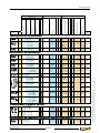
Measurement of AC/DC current
Specific features
● ●
0,05 A …1.5 A AC
0,05 A…10 A peak
1 A …100 A peak
Transformation ratio (input/output)
Lead + Ø 4 mm safety connectors(3)
DC…1.5 kHz
≤ 1 %
P01120074A
1A/1V
DC… 2 kHz
≤ 2 %
1 A / 1 mV
DC… 8 kHz
≤ 1.5 %
Automatic DC voltage
1 mA / 10 mV
BNC connector (coaxial)
●
Ø 4 mm female sockets
Voltage
3 V RMS
1.5 V AC
●
● ●
1 V peak
● ●
1.5 V AC
●
2 V DC
5 mA…1.5 A AC
20 mA…80 A AC/DC
PAC10
P01120067A
150 mV AC/ DC
5 mA…2 A DC
Chap. 10
≤ 1 %
2 V DC
● ●
0.5 A…150 A AC/DC
E6N
DC…2 kHz
4.5 V peak
0,05 A …2 A DC
E3N
1 mA / 1 mV
4.5 V AC
● ●
100 µA…450 mA peak
E1N
●
0.5 A…400 A AC
0.5 A…600 A DC
●
0,8 V AC/ DC
● ●
600 mV AC/DC ●
● ●
600 mV AC/DC ●
● ●
600 mV AC/DC
● ●
1.4 V AC/DC
●
● ●
1.4 V AC/DC
●
● ●
1.4 V AC/DC
1 A / 100 mV
DC…100 kHz
1 A / 10 mV
≤ 3 %
≤ 4 %
1A/1V
DC… 2 kHz
≤ 2 %
1 A / 10 mV
DC… 8 kHz
≤ 4 %
1 A / 1 mV
DC…5 kHz
≤ 2 %
P01120030A
P01120043A
P01120040A
P01120070
0.2 A…40 A AC
PAC11
0.4 A…60 A DC
0.5 A…400 A AC
1 A / 10 mV
1 A / 1 mV
●
DC…10 kHz
●
DC…10 kHz
≤ 1.5 %
≤ 2 %
P01120068
0.2 A…60 A peak
PAC12
Chap. 11
0.4 A…60 A DC
0.5 A…600 A peak
●
1 A / 10 mV
1 A / 1 mV
≤ 1.5 %
≤ 2 %
P01120072
0.5 A…600 A DC
PAC20
0.5 A…1000 A AC
0.5 A…1400 A DC
1 A / 1 mV
DC…5 kHz
≤ 2 %
P01120071
0.2 A…100 A AC
PAC21
0.4 A…150 A DC
0.5 A…1000 A AC
1 A / 10 mV
1 A / 1 mV
●
DC…10 kHz
●
DC…10 kHz
≤ 1.5 %
≤ 2.5 %
P01120069
0.5 A…1400 A DC
0.2 A…150 A peak
PAC22
Chap. 11
Non-contractual document
906111964 - Ed 3
0.4 A…150 A DC
0.5 A…1400 A peak
0.5 A…1400 A DC
i.3 (1/1)
●
1 A / 10 mV
1 A / 1 mV
≤ 1.5 %
≤ 2.5 %
P01120073
(1) The upper value corresponds to 120 % of the maximum rated value
0.5 A…600 A DC
(3) Lead + electronic unit with Ø 4 mm safety connectors, centre distance 19 mm, for K and AmpFLEX™ series
100 µA…300 mA RMS
3 V RMS
4.5 V peak
100 µA…450 mA DC
Chap. 9
To
order
4.5 V AC
1 mA…3 A RMS
1 mA…4.5 A peak
K2
Typical accuracy
K1
Bandwidth (frequency in Hz)
1 mA…4.5 A DC
Current
DC
AC
Strong current
Medium current
Weak current
Model
Very weak current
Series
Measurement of power (slight phase shift)
Output - Connections
Measuring range (1)
Output protected against voltage surges
Input
Selection guide
Selection guide
Typical accuracy
Bandwidth (frequency in Hz)
Transformation ratio (input/output)
BNC connector (coaxial)
Ø 4 mm female sockets
Lead + Ø 4 mm safety connectors(3)
Voltage
Current
DC
AC
Strong current
Medium current
Weak current
Model
Very weak current
Series
Measurement of power (slight phase shift)
Specific features
Automatic DC voltage
Output - Connections
Output protected against voltage surges
Input
Measuring range (1)
Leakage current measurement
Chap. 2
MN73
●
2 V AC
2 V AC
●
1 A / 1000 mV
1 A / 10 mV
40 Hz…10 kHz
≤ 1 %
≤ 2 %
P01120421
10 Hz…3 kHz
≤ 0.7 %
≤ 0.3 %
≤ 0.5 %
≤ 0.2 %
P01120309
10 Hz…1 kHz
≤ 0.5 %
P01120083
≤ 0.35 %
C173
1 mA…1.2A
0,01 A…12 A
0.1 A…120 A
1 A…1200 A
●
1 V AC
●
1A/1V
10 A / 1 V
100 A / 1 V
1000 A / 1 V
B102
500 μA…4 A
0.5 A…400 A
●
4 V AC
0.4 V AC
●
1 mA / 1 mV
1 A / 1 mV
Chap. 4
Chap. 6
10 mA…2,4 A
100 mA…240 A
To
order
●
Chap. 3
MN60
0.1 A…60 A peak
0.5 A…600 A peak
●
2 V AC
2 V AC
●
1 A / 100 mV
1 A / 10 mV
40 Hz…40 kHz
≤ 2 %
≤ 1.5 %
P01120409
Y7N
1 A…1200 A peak
●
1 V AC
●
1 mA / 1 mV
5 Hz…10 kHz
≤ 2 %
P01120075
C160
0.1 A…30 A peak
1 A…300 A peak
1 A…2000 A peak
●
3 V peak
3 V peak
2 V peak
●
10 A / 1 V
100 A / 1 V
1000 A / 1 V
≤ 3 %
10 Hz…100 kHz ≤ 2 %
≤ 1 %
P01120308
●
1 V AC
●
1 A / 10 V
1 A / 1 mV
1 A / 0.1 mV
30 Hz…50 kHz
≤ 2 %
P01120057A
1 V peak
●
1 A / 10 mV
1 A / 1 mV
DC…100 kHz
≤ 3 %
≤ 4 %
P01120043A
≤ 1 %
+ 0.3 A
P01120570
≤ 1 %
+ 0.3 A
P01120571
≤ 1 %
+ 0.3 A
P01120572
Chap. 4
D38N
Chap. 5
Chap. 10
MA 200
E3N
MA200
30-300/3
(17 cm)
MA200
30-300/3
(25 cm)
Chap. 7
1 A…90 A peak
1 A…900 A peak
1 A…9000 A peak
0,05 A…10 A peak
1 A…100 A peak
●
●
0.5 A…45 A peak
0.5 A…450 A peak
●
4.5 V peak
●
100 mV/A
10 mV/A
0.5 A…45 A peak
0.5 A…450 A peak
●
4.5 V peak
●
100 mV/A
10 mV/A
4.5 V peak
●
1 mV/A
5 Hz…1 MHz
MA200
3000 /3
(35 cm)
5 A…4500 A peak
●
PAC12
0.2 A…60 A peak
0.4 A…60 A DC
0.5 A…600 A peak
0.5 A…600 A DC
●
●
600 mV AC/DC
●
1 A / 10 mV
1 A / 1 mV
●
DC…10 kHz
≤ 1.5 %
≤ 2 %
P01120072
PAC22
0.2 A…150 A peak
0.4 A…150 A DC
0.5 A…1400 A peak
0.5 A…1400 A DC
●
●
1.4 V AC/DC
●
1 A / 10 mV
1 A / 1 mV
●
DC…10 kHz
≤ 1.5 %
≤ 2.5 %
P01120073
Chap. 11
Chap. 11
Measurement of process current
K1
1 mA…4.5 A DC
1 mA…3 A RMS
1 mA…4.5 A peak
●
●
4.5 V DC
3 V RMS
4.5 V peak
●
1 mA / 1 mV
DC…2 kHz
≤ 1 %
P01120067A
K2
100 μA…450 mA DC
100 μA…300 mA RMS
100 μA …450 mA peak
●
●
4.5 V DC
3 V RMS
4.5 V peak
●
1 mA / 10 mV
DC…1.5 kHz
≤ 1 %
P01120074A
40 Hz…10 kHz
≤ 1 %
P01120420
Chap. 9
Measurement on secondary winding of current transformers
Chap. 2
MN71
Non-contractual document
906111964 - Ed 3
10 mA…12 A
●
1 V AC
i.4 (1/1)
●
1 A / 100 mV
(3) Lead + electronic unit with Ø 4 mm safety connectors, centre distance 19 mm, for K and AmpFLEX™ series
Chap. 2
(1) The upper value corresponds to 120 % of the maximum rated value
Measurement on oscilloscope
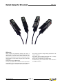
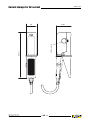
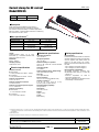
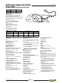
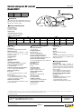
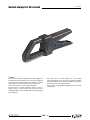
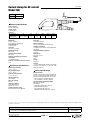
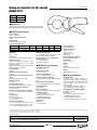
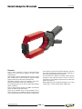
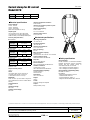
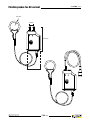
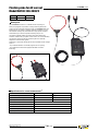
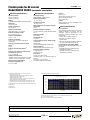
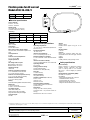
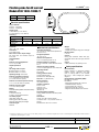
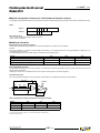
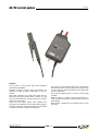
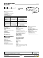
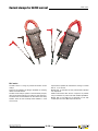
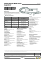
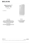
Current clamps for AC current
MINI series
MINI series
Small, compact and particularly resistant, this range of
miniature clamps is designed for measurements from a few
milli-amperes to 150 A AC. Their shape makes them very
practical in confined spaces, such as circuit-breaker boards,
control panels or control boxes. They are ideal for use with
multimeters.
There are two types of MINI clamps.
The first type operates like a traditional current transformer
and provides a current output (mA) which can be used with
multimeters, loggers or instruments with current calibres.
Non-contractual document
906131099 - Ed 3 - 00
The second provides a voltage output proportional to the
current measured.
This voltage output enables instruments with AC voltage
calibres to display or store current values.
There is also a model with a DC voltage output.
The MINI clamps give True RMS results when used with a
True RMS instrument.
1.00 (1/2)
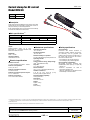
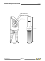
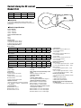
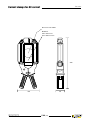
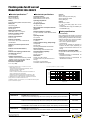
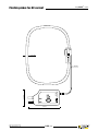
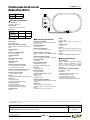
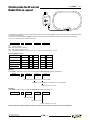
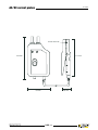
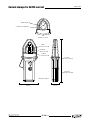
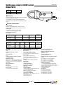
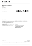
Current clamps for AC current
MINI series
26
37.50
Ø 10 mm max.
112.50
Non-contractual document
906131099 - Ed 3 - 00
1.00 (2/2)
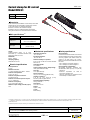
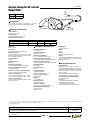
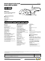
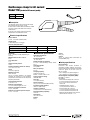
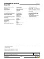
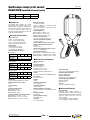
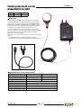
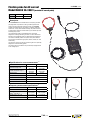
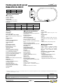
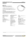
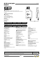
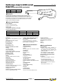
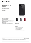
Current clamp for AC current
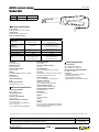
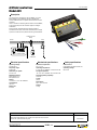
Model MINI 01
Calibre
Sensitivity
MINI series
150 A AC
1 mA / A (1000 / 1)
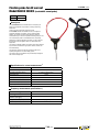
Description
Small and compact, the MINI 01 current clamp is the ideal
complement for any multimeter to measure AC currents
in low-power tertiary or industrial applications.
If there is a current in the conductor clamped,
the MINI 01 clamp is protected against overvoltages
during disconnection from the measurement instrument.
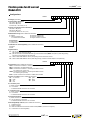
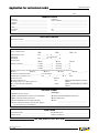
Main specifications (1)
Calibre
Measurement range
Accuracy in %
Phase shift
Output signal
150 A
2 A …150 A
≤ 2.5 % + 0.15 A (load 1 Ω)
≤ 3 % + 0.15 A (load 10 Ω)
not specified
1 mA AC / A AC (1000 / 1)
(150 mA for 150 A)
Output:
Double-insulated cable 1.5 m long,
terminated by 2 insulated elbowed male
banana connectors Ø 4 mm
Bandwidth:
48 Hz …500 Hz
Clamping capacity:
Cable Ø max 10 mm
Electrical specifications
Load impedance:
≤ 10 Ω
Maximum currents:
I < 150 A permanent from 48 Hz …500 Hz
Influence of temperature:
≤ 0.2 % per 10 °K
Influence of adjacent conductor:
≤ 2 mA / A at 50 Hz
Influence of conductor position in jaws:
≤ 0.1 % at 50/60 Hz
Influence of frequency:
≤ 2 % from 65 Hz to 500 Hz
Maximum output voltage (secondary open):
30 V
Mechanical specifications
Operating temperature:
-10 °C to +50 °C
Storage temperature:
-40 °C to +80 °C
Relative humidity for operation:
From 0 to 85 % RH with a linear decrease
above 35 °C
Operating altitude:
0 to 2,000 m
Casing protection rating (leakproofing):
IP40 (2) (EN 60529 Ed. 1992)
Drop test:
1.5 m (IEC 68-2-32)
Shock resistance:
100 g / 6 ms / half-period (IEC 68-2-27)
Vibration resistance (3):
5-15 Hz (1.5 mm), 15-25 Hz (1 mm),
25-55 Hz (0.25 mm) (IEC 68-2-6)
Self-extinguishing capability:
casing UL94 V2
Dimensions:
130 x 37 x 25 mm
Weight:
approx. 180 g
Colour:
Black casing
Safety specifications
Electrical safety:
Instrument with double insulation or reinforced
insulation between the primary, the secondary
and the grippable part located under the
guard as per EN 61010-1 Ed. 2:2001,
EN 61010-2-031 Ed. 2002 & EN 61010-2-032
Ed. 2003
- 600 V category III, pollution degree 2
- 300 V category IV, pollution degree 2
Electromagnetic compatibility:
CE-certified equipment compliant with
standard EN 61326-1 (Ed. 97) + A1 (Ed. 98)
+ A2 (Ed. 01)
- Emission: stipulations for class B
equipment (domestic use).
- Immunity: stipulations for equipment used
intermittently on industrial sites.
(1) Conditions of reference: 23 °C ± 3 °K, 20 °C to 75 % RH, sinusoidal signal with frequency of 48 Hz to 65 Hz, distortion factor < 1 % with no DC component, external DC magnetic field < 40 A/m,
no external AC magnetic field, no external conductor with circulating current, conductor centred for measurement, measurement instrument load impedance ≤ 10 Ω.
(2)With clamp closed.
(3) Vibrations expressed in mm peak, scanning of 1 octave/minute for 10 minutes on 3 axes.
To order
Reference
AC current clamp model MINI 01 with operating manual
Non-contractual document
906131099 - Ed 3 - 01
P01105101Z
1.01 (1/1)
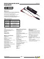
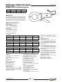
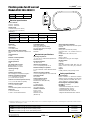
Current clamp for AC current
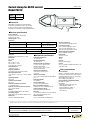
Model MINI 02
Calibre
Sensitivity
MINI series
100 A AC
1 mA / A (1000 / 1)
Description
The MINI 02 current clamp, whose jaws are equipped with a
high-performance magnetic material and a double coil, offers
excellent linearity and improved performance.
Small and compact, it is ideal for measuring AC currents in
low-power tertiary or industrial applications.
If a current is present in the conductor being clamped,
the MINI 02 clamp is protected against voltage surges when it
is disconnected from the measurement instrument.
Main specifications (1)
Calibre
Measurement range
Accuracy in %
(48 Hz to 10 kHz)
Phase shift
(50 Hz to 60 Hz)
Output signal
100 A
50 mA .. 100 A (load 1 Ω)
50 mA .. 90 A (load 10 Ω)
≤ 1 % + 0.02 A (load 1 Ω)
≤ 1.5 % + 0.01 A (load 10 Ω)
≤ 3° (load 1 Ω)
≤ 6° (load 10 Ω)
1 mA AC / A AC (1000 / 1)
(100 mA for 100 A)
Output:
Double-insulated cable 1.5 m long,
terminated by 2 insulated elbowed male
banana connectors Ø 4 mm
Bandwidth:
48 Hz …10 000 Hz
Clamping capacity:
Cable Ø max 10 mm
Electrical specifications
Load impedance:
≤ 100 Ω
Influence of load impedance:
see curves
Maximum currents:
I < 100 A permanent from 48 Hz …10,000 Hz
Influence of temperature:
≤ 0.2 % per 10 °K
Influence of adjacent conductor:
≤ 2 mA / A at 50 Hz
Influence of conductor position in jaws:
≤ 0.1 % at 50/60 Hz
Influence of frequency:
≤ 2 % from 65 Hz to 500 Hz
Maximum output voltage
(secondary open):
≤ 30 V
Non-contractual document
906131099 - Ed 3 - 02
Mechanical specifications
Operating temperature:
-10 °C to +50 °C
Storage temperature:
-40 °C to +80 °C
Relative humidity for operation:
From 0 to 85 % RH with a linear decrease
above 35 °C
Operating altitude:
0 to 2,000 m
Casing protection rating (leakproofing):
IP40 (2) (EN 60529 Ed. 1992)
Drop test:
1.5 m (IEC 68-2-32)
Shock resistance:
100 g / 6 ms / half-period (IEC 68-2-27)
Vibration resistance (3):
5-15 Hz (1.5 mm), 15-25 Hz (1 mm),
25-55 Hz (0.25 mm) (IEC 68-2-6)
Self-extinguishing capability:
Casing UL94 V2
Dimensions:
130 x 37 x 25 mm
Weight:
Approx. 180 g
Colour:
Black casing
1.02 (1/2)
Safety specifications
Electrical safety:
Instrument with double insulation or reinforced
insulation between the primary, the secondary
and the grippable part located under the
guard as per EN 61010-1 Ed. 2:2001,
EN 61010-2-031 Ed. 2002 & EN 61010-2-032
Ed. 2003
- 600 V category III, pollution degree 2
- 300 V category IV, pollution degree 2
Electromagnetic compatibility:
CE-certified equipment compliant with
standard EN 61326-1 (Ed. 97) + A1 (Ed. 98)
+ A2 (Ed. 01)
- Emission: stipulations for class B
equipment (domestic use).
- Immunity: stipulations for equipment used
intermittently on industrial sites.
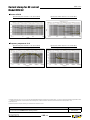
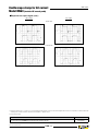
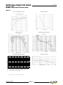
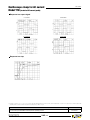
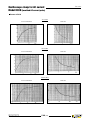
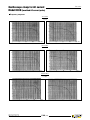
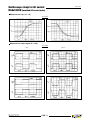
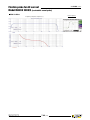
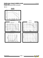
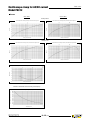
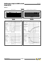
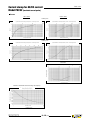
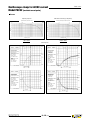
Current clamp for AC current
Model MINI 02
MINI series
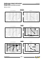
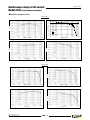
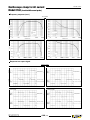
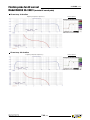
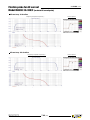
Curves at 50 Hz
Typical linearity error for loads of 1, 10, 30 and 100 Ω
Typical phase shift for loads of 1, 10, 30 and 100 Ω
Frequency response at 10 A
Typical linearity error for loads of 1, 10, 30 and 100 Ω
Typical phase shift for loads of 1, 10, 30 and 100 Ω
(1) Conditions of reference: 23 °C ± 3 °K, 20 °C to 75 % RH, sinusoidal signal with frequency of 48 Hz at 10 kHz, distortion factor < 1 % with no DC component, external DC magnetic field < 40 A/m,
no external AC magnetic field, no external conductor with circulating current, conductor centred for measurement, measurement instrument load impedance ≤ 10 Ω.
(2)With clamp closed.
(3) Vibrations expressed in mm peak, scanning of 1 octave/minute for 10 minutes on 3 axes.
To order
Reference
AC current clamp model MINI 02 with operating manual
Non-contractual document
906131099 - Ed 3 - 02
P01105102Z
1.02 (2/2)
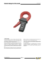
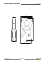
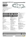
Current clamp for AC current
Model MINI 03
Calibre
100 A AC
Sensitivity
1 mV / A
MINI series
Description
Small and compact, the MINI 03 current clamp is the
ideal complement for any multimeter to measure AC
currents in low-power tertiary or industrial applications.
When used with an AC voltmeter, it allows you to directly
read the current measured on the voltmeter.
Main specifications (1)
Calibre
Measurement range
Accuracy in %
Phase shift
Output signal
100 A
1 A …100 A
≤ 2 % + 50 mA
not specified
1 mV AC / A AC
(100 mV for 100 A)
Output:
Double-insulated cable 1.5 m long,
terminated by 2 insulated elbowed male
banana connectors Ø 4 mm
Bandwidth:
48 Hz …500 Hz
Clamping capacity:
Cable Ø max 10 mm
Electrical specifications
Maximum currents:
I < 150 A permanent from 48 Hz …500 Hz
Influence of temperature:
≤ 0.2 % per 10 °K
Influence of adjacent conductor:
≤ 2 mA / A at 50 Hz
Influence of conductor position in jaws:
≤ 0.1 % at 50/60 Hz
Influence of frequency:
≤ 1 % from 65 Hz to 500 Hz
Mechanical specifications
Operating temperature:
-10 °C to +50 °C
Storage temperature:
-40 °C to +80 °C
Relative humidity for operation:
from 0 to 85 % RH with a linear decrease
above 35 °C
Operating altitude:
0 to 2,000 m
Casing protection rating (leakproofing):
IP40 (2) (EN 60529 Ed. 1992)
Drop test:
1.5 m (IEC 68-2-32)
Shock resistance:
100 g / 6 ms / half-period (IEC 68-2-27)
Vibration resistance (3):
5-15 Hz (1.5 mm), 15-25 Hz (1 mm),
25-55 Hz (0.25 mm) (IEC 68-2-6)
Self-extinguishing capability:
Casing UL94 V2
Dimensions:
130 x 37 x 25 mm
Weight:
Approx. 180 g
Colour:
Black casing
Safety specifications
Electrical safety:
Instrument with double insulation or reinforced
insulation between the primary, the secondary
and the grippable part located under the
guard as per EN 61010-1 Ed. 2:2001,
EN 61010-2-031 Ed. 2002 & EN 61010-2-032
Ed. 2003
- 600 V category III, pollution degree 2
- 300 V category IV, pollution degree 2
Electromagnetic compatibility:
CE-certified equipment compliant with
standard EN 61326-1 (Ed. 97) + A1 (Ed. 98)
+ A2 (Ed. 01)
- Emission: stipulations for class B
equipment (domestic use).
- Immunity: stipulations for equipment used
intermittently on industrial sites.
(1) Conditions of reference: 23 °C ± 3 °K, 20 °C to 75 % RH, sinusoidal signal with frequency of 48 Hz to 65 Hz, distortion factor < 1 % with no DC component, external DC magnetic field < 40 A/m,
no external AC magnetic field, no external conductor with circulating current, conductor centred for measurement, measurement instrument load impedance ≥ 10 kΩ.
(2)With clamp closed.
(3)Vibrations expressed in mm peak, scanning of 1 octave/minute for 10 minutes on 3 axes.
To order
Reference
AC current clamp model MINI 03 with operating manual
Non-contractual document
906131099 - Ed 3 - 03
P01105103Z
1.03 (1/1)
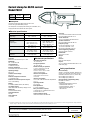
Current clamp for AC current
Model MINI 05
Calibre
Sensitivity
10 A AC
100 A AC
1 mV / mA
1 mV / A
MINI series
Description
Small and compact, the MINI 05 current clamp is
the ideal complement for any multimeter to measure
AC currents in low-power tertiary or industrial applications.
With its 2 calibres, it offers excellent resolution for measuring
AC currents from 5 mA to 100 A.
Main specifications (1)
Calibre
Measurement range
Accuracy in %
Phase shift
Output signal
10 A
5 mA …10 A
≤ 3 % + 0.15 mA
1 mV AC/ mA AC
(10 V for 10 A)
Output:
Double-insulated cable 1.5 m long,
terminated by 2 insulated elbowed male
banana connectors Ø 4 mm
Bandwidth:
48 Hz …500 Hz
Clamping capacity:
Cable Ø max 10 mm
Electrical specifications
Maximum currents:
n 100 A calibre
I < 150 A permanent from 48 Hz …500 Hz
n 10 A calibre
I < 15 A permanent from 48 Hz …500 Hz
Influence of temperature:
≤ 0.2 % per 10 °K
Influence of adjacent conductor:
≤ 2 mA / A at 50 Hz
Influence of conductor position in jaws:
≤ 0.1 % at 50/60 Hz
Influence of frequency:
n 100 A calibre:
≤ 1 % from 65 Hz to 500 Hz
n 10 A calibre:
≤ 3 % from 65 Hz to 500 Hz
not specified
100 A
1 A …100 A
≤ 2 % + 50 mA
1 mV AC / A AC
(100 mV for 100 A)
Mechanical specifications
Operating temperature:
-10 °C to +50 °C
Storage temperature:
-40 °C to +80 °C
Relative humidity for operation:
from 0 to 85 % RH with a linear decrease
above 35 °C
Operating altitude:
0 to 2,000 m
Casing protection rating (leakproofing):
IP40 (2) (EN 60529 Ed. 1992)
Drop test:
1.5 m (IEC 68-2-32)
Shock resistance:
100 g / 6 ms / half-period (IEC 68-2-27)
Vibration resistance (3):
5-15 Hz (1.5 mm), 15-25 Hz (1 mm),
25-55 Hz (0.25 mm) (IEC 68-2-6)
Self-extinguishing capability:
casing UL94 V2
Dimensions:
130 x 37 x 25 mm
Weight:
Approx. 180 g
Colour:
Black casing
Safety specifications
Electrical safety:
Instrument with double insulation or reinforced
insulation between the primary, the secondary
and the grippable part located under the
guard as per EN 61010-1 Ed. 2:2001,
EN 61010-2-031 Ed. 2002 & EN 61010-2-032
Ed. 2003
- 600 V category III, pollution degree 2
- 300 V category IV, pollution degree 2
Electromagnetic compatibility:
CE-certified equipment compliant with
standard EN 61326-1 (Ed. 97) + A1 (Ed. 98)
+ A2 (Ed. 01)
- Emission: stipulations for class B
equipment (domestic use).
- Immunity: stipulations for equipment used
intermittently on industrial sites.
(1)Conditions of reference: 23 °C ± 3 °K, 20 °C to 75 % RH, sinusoidal signal with frequency of 48 Hz to 65 Hz, distortion factor < 1 % with no DC component, external DC magnetic field < 40 A/m,
no external AC magnetic field, no external conductor with circulating current, conductor centred for measurement, measurement instrument load impedance ≥ 1 MΩ (10 A calibre) & ≥ 10 kΩ
(100 A calibre).
(2)With clamp closed.
(3) Vibrations expressed in mm peak, scanning of 1 octave/minute for 10 minutes on 3 axes.
To order
Reference
AC current clamp model MINI 05 with operating manual
Non-contractual document
906131099 - Ed 3 - 04
P01105105Z
1.04 (1/1)
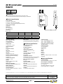
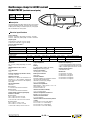
Current clamp for AC current
Model MINI 09
Calibre
Sensitivity
MINI series
150 A AC
100 mV DC / A AC
Description
Small and compact, the MINI 09 current clamp is the ideal
complement for any multimeter to measure AC currents in
low-power tertiary or industrial applications.
Its DC voltage output helps to overcome the low sensitivity
of certain AC measurement instruments.
Main specifications (1)
Calibre
Measurement range
Accuracy in %
Phase shift
1 A …5 A
≤ 10 % + 0.2 A
Output signal
5 A …15 A
≤ 6 % + 0.2 A
15 A …40 A
≤ 3 % + 0.2 A
not specified
40 A …150 A
≤ 4 %
100 mV DC / A AC (15 V DC for 150 A)
Output:
Double-insulated cable 1.5 m long,
terminated by 2 insulated elbowed male
banana connectors Ø 4 mm
Bandwidth:
48 Hz …500 Hz
Clamping capacity:
Cable Ø max 10 mm
Electrical specifications
150 A
Maximum currents:
I < 150 A permanent from 65 Hz …500 Hz
Influence of temperature:
≤ 0.2 % per 10 °K
Influence of adjacent conductor:
≤ 2 mA / A at 50 Hz
Influence of conductor position in jaws:
≤ 0.1 % at 50/60 Hz
Influence of frequency:
≤ 3 % from 65 Hz to 500 Hz
Mechanical specifications
Operating temperature:
-10 °C to +50 °C
Storage temperature:
-40 °C to +80 °C
Relative humidity for operation:
0 to 85 % RH decreasing linearly above 35 °C
Operating altitude:
0 to 2,000 m
Casing protection rating (leakproofing):
IP40 (2) (EN 60529 Ed. 1992)
Drop test:
1.5 m (IEC 68-2-32)
Shock resistance:
100 g / 6 ms / half-period (IEC 68-2-27)
Vibration resistance (3):
5-15 Hz (1.5 mm), 15-25 Hz (1 mm),
25-55 Hz (0.25 mm) (IEC 68-2-6)
Self-extinguishing capability:
Casing UL94 V2
Dimensions:
130 x 37 x 25 mm
Weight:
Approx. 180 g
Colour:
Black casing
Safety specifications
Electrical safety:
Instrument with double insulation or
reinforced insulation between the primary,
the secondary and the grippable part
located under the guard as per EN 61010-1
Ed. 2:2001, EN 61010‑2‑031 Ed. 2002 &
EN 61010‑2‑032 Ed. 2003
- 600 V category III, pollution degree 2
- 300 V category IV, pollution degree 2
Electromagnetic compatibility:
CE-certified equipment compliant with
standard EN 61326-1 (Ed. 97) + A1 (Ed. 98)
+ A2 (Ed. 01)
- Emission: stipulations for class B
equipment (domestic use).
- Immunity: stipulations for equipment used
intermittently on industrial sites.
(1)Conditions of reference: 23 °C ± 3 °K, 20 % to 75 % RH, sinusoidal signal with frequency of 48 Hz to 65 Hz, distortion factor < 1 % with no DC component, external DC magnetic field < 40 A/m,
no external AC magnetic field, no external conductor with circulating current, conductor centred for measurement, measurement instrument load impedance ≥ 50 kΩ.
(2)With clamp closed.
(3) Vibrations expressed in mm peak, scanning of 1 octave/minute for 10 minutes on 3 axes.
To order
Reference
AC current clamp model MINI 09 with operating manual
Non-contractual document
906131099 - Ed 3 - 05
P01105109Z
1.05 (1/1)
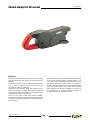
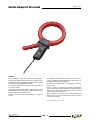
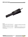
Current clamps for AC current
MN series
MN series
These ergonomic mini-clamps are designed to make light
work of measuring low and medium currents from 0.01 A to
240 A AC.
The shape of the jaws makes ‘hooking’ onto cables easy,
even in areas of restrictive access. The jaws can grip
conductors up to 20 mm in diameter.
Depending on the particular model, they have one or two
calibres. The output is via either jack sockets or a lead with
4 mm Ø plugs, hence these clamps are compatible with all
multimeters and testers on the market.
The second type gives a voltage output (DC or AC depending
on the model) proportional to the measured current (1, 10,
100 or 1000 mV/A). This voltage output means that, even
with testers without any current calibres, it is possible to
measure currents by means of the DC or AC voltage calibres.
There are specific models in the MN series that have
been designed with particular applications in mind such
as measurement on current transformer outputs, on
oscilloscopes and even of leakage currents.
There are two types of MN series clamps available.
The first kind operates as a current transformer (ratio 1000/1)
and gives a current output (mA) for use with any tester with
current calibres.
Non-contractual document
906111679 - Ed 3 - 00
2.00 (1/2)
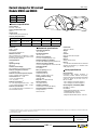
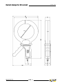
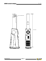
Current clamps for AC current
65
mm
21 mm
135 mm
18.5 mm
MN series
57 mm
34.5 mm
Non-contractual document
906111679 - Ed 3 - 00
2.00 (2/2)
Current clamps for AC current
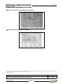
Models MN08 and MN09
Current
200 A AC
Ratio
1000 / 1
Output
1 mA / A
MN series
Electrical specifications
Current calibre:
0.5 A AC …240 A AC
Current transformation ratio:
1000 / 1
Output signal:
1 mA AC / A AC (240 mA for 240 A)
Accuracy and phase shift (1):
Primary current
% Accuracy
of output signal
Phase shift
0.5 A …10 A
10 A …40 A
40 A …100 A
100 A …240 A
≤ 3 % + 0.5 mA
≤ 2.5 % + 0.5 mA
≤ 2 % + 0.5 mA
≤ 1 % + 0.5 mA
not specified
≤ 5 °
≤ 3°
≤ 2.5 °
Bandwidth:
40 Hz …10 kHz
Crest factor:
3 for a current of 200 A rms
Maximum currents:
200 A continuous for a frequency ≤ 3 kHz
(limitation proportional to the inverse of one
third of frequency beyond)
Load impedance:
≤ 10 Ω
Operating voltage:
600 V rms
Common mode voltage:
600 V category III and pollution degree 2
Influence of adjacent conductor:
≤ 15 mA / A at 50 Hz
Influence of conductor position in jaws:
≤ 0.5 % of output signal at 50/60 Hz
Load influence: 0.2 …10 Ω
< 0.5 % on measurement
< 0.5 ° on phase
Influence of frequency (2):
< 3 % of output signal from 40 Hz …1 kHz
< 12 % of output signal from 1 kHz …10 kHz
Influence of crest factor:
< 4 % of output signal for a crest factor of 3
and current 200 of A rms
Mechanical specifications
Operating temperature:
-10 °C to +55 °C
Storage temperature:
-40 °C to +70 °C
Influence of temperature:
≤ 0.15 % of output signal per 10 °K
Relative humidity for operation:
0 to 85 % RH decreasing linearly above 35 °C
Influence of relative humidity:
< 0.2 % of output signal from 10 % to 85 % RH
Operating altitude:
0 to 2,000 m
Max. jaw opening: 20 mm
Clamping capacity:
Cable: ∅ max 20 mm
Busbar: 1 busbar of 20 x 5 mm
Casing protection rating:
IP40 (IEC 529)
Drop test: 1 m (IEC 68-2-32)
Shock resistance:
100 g (IEC 68-2-27)
Vibration resistance:
10 / 55/10 Hz, 0.15 mm (IEC 68-2-6)
Self-extinguishing capability:
Casing: UL94 V2
Jaws: UL94 V0
Dimensions:
135 x 51 x 30 mm
Weight:
180 g
Colours:
Dark grey case with red jaws
Output:
nMN08:
Safety sockets (4 mm)
nMN09:
1.5 m two-wire lead with double or reinforced
insulation terminated by 2 elbowed male
safety plugs (4 mm)
Safety specifications
Electrical safety:
Instrument with double insulation or
reinforced insulation between the primary,
the secondary and the grippable part located
under the guard as per IEC 1010-1 &
IEC 1010-2-032.
- 600 V category III, pollution degree 2
- 300 V category IV, pollution degree 2
Electromagnetic compatibility (EMC):
EN 50081-1: class B
EN 50082-2:
- Electrostatic discharge: IEC 1000-4-2
- Radiated field: IEC 1000-4-3
- Fast transients: IEC 1000-4-4
- Magnetic field at 50/60 Hz: IEC 1000-4-8
(1)Conditions of reference: 23 °C ± 3 °K, 20 to 70 % RH, sinusoidal signal with frequency of 48 Hz to 65 Hz, external magnetic field < 40 A/m, no DC components, no external conductor with
circulating current, conductor centred for measurement, 1 Ω load.
(2)Out of reference domain.
To order
Reference
AC current clamp model MN08 with operating manual
P01120401
AC current clamp model MN09 with operating manual
Non-contractual document
906111679 - Ed 3 - 01
P01120402
2.01 (1/1)
Current clamps for AC current
Models MN10 and MN11
Current
200 A AC
Ratio
1000 / 1
Output
1 mA / A
MN series
Description
An electronic voltage-limiting system protects output of
clamp when operating, if the secondary circuit is opened.
Electrical specifications
Current calibre:
0.5 A AC …240 A AC
Current transformation ratio:
1000 / 1
Output signal:
1 mA AC / A AC (240 mA for 240 A)
Accuracy and phase shift (1):
Primary current
Accuracy in % of output signal
Phase shift
Bandwidth:
40 Hz …10 kHz
Crest factor:
3 for a current of 200 A rms
Maximum currents:
200 A continuous for a frequency ≤ 3 kHz
(limitation proportional to the inverse of one
third of frequency beyond)
Load impedance:
≤ 10 Ω
Maximum output voltage
(secondary open):
Limited to 8 V peak max.
Operating voltage:
600 V rms
Common mode voltage:
600 V category III and pollution degree 2
Influence of adjacent conductor:
≤ 15 mA / A at 50 Hz
Influence of conductor position in jaws:
≤ 0.5 % of output signal at 50/60 Hz
Load influence: 0.2 …10 Ω
< 0.5 % on measurement
< 0.5 ° on phase
Influence of frequency (2):
< 3 % of output signal from 40 Hz …1 kHz
< 12 % of output signal from 1 kHz …10 kHz
Influence of crest factor:
< 4 % of output signal for a crest factor of 3
and current of 200 A rms
0.5 A …10 A
150 A …200 A
200 A …240 A
≤ 3 % + 0.5 mA ≤ 2.5 % + 0.5 mA ≤ 2 % + 0.5 mA ≤ 1 % + 0.5 mA ≤ 2 % + 0.5 mA
≤ 3 % + 0.5 mA
not specified
10 A …40 A
≤ 5°
40 A…100 A
≤ 3°
Mechanical specifications
Operating temperature:
-10 °C to +55 °C
Storage temperature:
-40 °C to +70 °C
Influence of temperature:
≤ 0.15 % of output signal per 10 °K
Relative humidity for operation:
0 to 85 % RH decreasing linearly above 35 °C
Influence of relative humidity:
< 0.2 % of output signal from 10 % to 85 % RH
Operating altitude:
0 to 2,000 m
Max. jaw opening:
20 mm
Clamping capacity:
Cable: ∅ max 20 mm
Busbar: 1 busbar of 20 x 5 mm
Casing protection rating:
IP40 (IEC 529)
Drop test:
1 m (IEC 68-2-32)
Shock resistance:
100 g (IEC 68-2-27)
Vibration resistance:
10 / 55/10 Hz, 0.15 mm (IEC 68-2-6)
Self-extinguishing capability:
Casing: UL94 V2
Jaws: UL94 V0
100 A …150 A
≤ 2.5°
≤ 2.5°
≤ 2.5°
Dimensions:
135 x 51 x 30 mm
Weight:
180 g
Colours:
Dark grey case with red jaws
Output:
nMN10:
Safety sockets (4 mm)
nMN11:
1.5 m two-wire lead with double or reinforced
insulation terminated by 2 elbowed male
safety plugs (4 mm)
Safety specifications
Electrical safety:
Instrument with double insulation or
reinforced insulation between the primary,
the secondary and the grippable part located
under the guard as per IEC 1010-1 &
IEC 1010-2-032
- 600 V category III, pollution degree 2
- 300 V category IV, pollution degree 2
Electromagnetic compatibility (EMC):
EN 50081-1: class B
EN 50082-2:
- Electrostatic discharge: IEC 1000-4-2
- Radiated field: IEC 1000-4-3
- Fast transients: IEC 1000-4-4
- Magnetic field at 50/60 Hz: IEC 1000-4-8
(1)Conditions of reference: 23 °C ± 3 °K, 20 to 70 % RH, sinusoidal signal with frequency of 48 Hz to 65 Hz, external magnetic field < 40 A/m, no DC components, no external conductor with
circulating current, conductor centred for measurement, 1 Ω load.
(2)Out of reference domain.
To order
Reference
AC current clamp model MN10 with operating manual
P01120403
AC current clamp model MN11 with operating manual
Non-contractual document
906111679 - Ed 3 - 02
P01120404
2.02 (1/1)
Current clamps for AC current
Models MN12 and MN13
Current
200 A AC
Output
10 mV / A
MN series
Electrical specifications
Current calibre:
0.5 A AC …240 A AC
Output signal:
10 mV AC / A AC (2.4 V for 240 A)
Accuracy and phase shift (1):
Primary current
% Accuracy
of output signal
Phase shift
0.5 A …10 A
10 A …40 A
40 A …100 A
100 A …240 A
≤ 3.5 % + 5 mV
≤ 2.5 % + 5 mV
≤ 2 % + 5 mV
≤ 1 % + 5 mV
not specified
≤ 5 °
≤ 3°
≤ 2.5 °
Bandwidth:
40 Hz …10 kHz
Crest factor:
3 for a current of 200 A rms
Maximum currents:
200 A continuous for a frequency ≤ 1 kHz
(derating proportional to the inverse of
frequency beyond)
Load impedance:
> 1 MΩ
Operating voltage:
600 V rms
Common mode voltage:
600 V category III and pollution degree 2
Influence of adjacent conductor:
≤ 15 mA / A at 50 Hz
Influence of conductor position in jaws:
≤ 0.5 % of output signal at 50/60 Hz
Influence of frequency (2):
< 3 % of output signal from 40 Hz …1 kHz
< 12 % of output signal from 1 kHz …10 kHz
Influence of crest factor:
< 3 % of output signal for a crest factor of 3
and current of 200 A rms
Mechanical specifications
Operating temperature:
-10 °C to +55 °C
Storage temperature:
-40 °C to +70 °C
Influence of temperature:
≤ 0.15 % of output signal per 10 °K
Relative humidity for operation :
0 to 85 % RH decreasing linearly above 35 °C
Influence of relative humidity:
< 0.2 % of output signal from 10 % to 85 % RH
Operating altitude:
0 to 2,000 m
Max. jaw opening:
20 mm
Clamping capacity:
Cable: ∅ max 20 mm
Busbar: 1 busbar of 20 x 5 mm
Casing protection rating:
IP40 (IEC 529)
Drop test: 1 m (IEC 68-2-32)
Shock resistance:
100 g (IEC 68-2-27)
Vibration resistance:
10 / 55/10 Hz, 0.15 mm (IEC 68-2-6)
Self-extinguishing capability:
Casing: UL94 V2
Jaws: UL94 V0
Dimensions:
135 x 51 x 30 mm
Weight:
180 g
Colours:
Dark grey case with red jaws
Output:
nMN12:
Safety sockets (4 mm)
nMN13:
1.5 m two-wire lead with double or reinforced
insulation terminated by 2 elbowed male
safety plugs (4 mm)
Safety specifications
Electrical safety:
Instrument with double insulation or
reinforced insulation between the primary,
the secondary and the grippable part located
under the guard as per IEC 1010-1 &
IEC 1010-2-032
- 600 V category III, pollution degree 2
- 300 V category IV, pollution degree 2
Electromagnetic compatibility (EMC):
EN 50081-1: class B
EN 50082-2:
- Electrostatic discharge: IEC 1000-4-2
- Radiated field: IEC 1000-4-3
- Fast transients: IEC 1000-4-4
- Magnetic field at 50/60 Hz: IEC 1000-4-8
(1)Conditions of reference: 23 °C ± 3 °K, 20 to 70 % RH, sinusoidal signal with frequency of 48 Hz to 65 Hz, external magnetic field < 40 A/m, no DC components, no external conductor with
circulating current, conductor centred for measurement, load impedance > 1 MΩ.
(2)Out of reference domain To order
Reference
AC current clamp model MN12 with operating manual
P01120405
AC current clamp model MN13 with operating manual
Non-contractual document
906111679 - Ed 3 - 03
P01120406
2.03 (1/1)
Current clamps for AC current
Models MN14 and MN15
Current
200 A AC
Output
1 mV / A
MN series
Electrical specifications
Current calibre:
0.5 A AC …240 A AC
Output signal:
1 mV AC / A AC (240 mV for 240 A)
Accuracy and phase shift (1):
Primary current
% Accuracy
of output signal
Phase shift
0.5 A …10 A
10 A …40 A
40 A …100 A
100 A …240 A
≤ 3 % + 5 mV
≤ 2.5 % + 5 mV
≤ 2 % + 5 mV
≤ 1 % + 5 mV
not specified
≤ 5 °
≤ 3°
≤ 2.5 °
Bandwidth:
40 Hz …10 kHz
Crest factor:
3 for a current of 200 A rms
Maximum currents:
200 A continuous for a frequency ≤ 1 kHz
(limitation proportional to the inverse of
frequency beyond)
Load impedance:
> 1 MΩ
Operating voltage:
600 V rms
Common mode voltage:
600 V category III and pollution degree 2
Influence of adjacent conductor:
≤ 15 mA / A at 50/60 Hz
Influence of conductor position in jaws:
≤ 0.5 % of output signal at 50/60 Hz
Influence of frequency (2):
< 3 % of output signal from 40 Hz …1 kHz
< 12 % of output signal from 1 kHz …10 kHz
Influence of crest factor:
< 3 % of output signal for a crest factor of 3
and current of 200 A rms
Mechanical specifications
Operating temperature:
-10 °C to +55 °C
Storage temperature:
-40 °C to +70 °C
Influence of temperature:
≤ 0.15 % of output signal per 10 °K
Relative humidity for operation:
0 to 85 % RH decreasing linearly above 35 °C
Influence of relative humidity:
< 0.2 % of output signal of 10 % at 90 % RH
Operating altitude:
0 to 2,000 m
Max. jaw opening:
20 mm
Clamping capacity:
Cable: Ø max 20 mm
Busbar: 1 busbar of 20 x 5 mm
Casing protection rating:
IP40 (IEC 529)
Drop test:
1 m (IEC 68-2-32)
Shock resistance:
100 g (IEC 68-2-27)
Vibration resistance:
10 / 55/10 Hz, 0.15 mm (IEC 68-2-6)
Self-extinguishing capability:
Casing: UL94 V2
Jaws: UL94 V0
Dimensions:
135 x 51 x 30 mm
Weight:
180 g
Colours:
Dark grey case with red jaws
Output:
nMN14:
Safety sockets (4 mm)
nMN15:
1.5 m two-wire lead with double or reinforced
insulation terminated by 2 elbowed male
safety plugs (4 mm)
Safety specifications
Electrical safety:
Instrument with double insulation or
reinforced insulation between the primary,
the secondary and the grippable part located
under the guard as per IEC 1010-1 &
IEC 1010-2-032
- 600 V category III, pollution degree 2
- 300 V category IV, pollution degree 2
Electromagnetic compatibility (EMC):
EN 50081-1: class B
EN 50082-2:
- Electrostatic discharge: IEC 1000-4-2
- Radiated field: IEC 1000-4-3
- Fast transients: IEC 1000-4-4
- Magnetic field at 50 Hz: IEC 1000-4-8
(1)Conditions of reference: 23 °C ± 3 °K, 20 to 70 % RH, sinusoidal signal with frequency of 48 Hz to 65 Hz, external magnetic field < 40 A/m, no DC components, no external conductor with
circulating current, conductor centred for measurement, load impedance > 1 MΩ.
(2)Out of reference domain
To order
Reference
AC current clamp model MN14 with operating manual
P01120416
AC current clamp model MN15 with operating manual
Non-contractual document
906111679 - Ed 3 - 04
P01120417
2.04 (1/1)
Current clamp for AC current
Model MN21
Current
200 A AC
Ratio
1000 / 1
Output
1 mA / A
MN series
Description
An electronic voltage-limiting system protects output of
clamp when operating, if the secondary circuit is opened.
Electrical specifications
Current calibre:
0.1 A AC …240 A AC
Current transformation ratio: 1000 / 1
Output signal:
1 mA AC / A AC (240 mA for 240 A)
Accuracy and phase shift (1):
Primary current
% Accuracy
of output signal
0.1 A …10 A
1 A …20 A
20 A …80 A
80 A …150 A
150 A …200 A
≤ 2 % + 20 µA
≤ 1 % + 20 µA
≤ 1 %
≤ 2 %
≤ 4 %
not specified
≤ 2°
≤ 1.5 °
≤ 1.5 °
≤ 2°
Phase shift
Bandwidth:
40 Hz …10 kHz
Crest factor:
5 for a current of 280 A peak
Maximum currents:
200 A continuous for a frequency ≤ 3 kHz
(limitation proportional to the inverse of one
third of frequency beyond)
Load impedance:
≤ 10 Ω
Maximum output voltage
(secondary open):
Limited to 8 V peak max.
Operating voltage:
600 V rms
Common mode voltage:
600 V category III and pollution degree 2
Influence of adjacent conductor:
≤ 15 mA / A at 50 Hz
Influence of conductor position in jaws:
≤ 0.5 % of output signal at 50/60 Hz
Load influence:
0.1 …5 Ω
< 0.5 % on measurement
< 0.5 ° on phase
Influence of frequency Ip < 150 A (2):
< 5 % of output signal from 40 Hz …1 kHz
< 15 % of output signal from 1 kHz …10 kHz
add 5 % error if 150 A < Ip < 200 A
Influence of crest factor:
< 3 % of output signal for crest factor < 5 with
current < 280 A peak (50 A rms)
Mechanical specifications
Operating temperature:
-10 °C to +55 °C
Storage temperature:
-40 °C to +70 °C
Influence of temperature:
≤ 0.20 % of output signal per 10 °K
Relative humidity for operation:
0 to 85 % RH decreasing linearly above 35 °C
Influence of relative humidity:
< 0.2 % of output signal from 10 % to 85 % RH
Operating altitude:
0 to 2,000 m
Max. jaw opening:
20 mm
Clamping capacity:
Cable: Ø max 20 mm
Busbar: 1 busbar of 20 x 5 mm
Casing protection rating:
IP40 (IEC 529)
Drop test: 1 m (IEC 68-2-32)
Shock resistance:
100 g (IEC 68-2-27)
Vibration resistance:
10 / 55/10 Hz, 0.15 mm (IEC 68-2-6)
Self-extinguishing capability:
Casing: UL94 V2
Jaws: UL94 V0
Dimensions:
135 x 51 x 30 mm
Weight:
180 g
Colours:
Dark grey case with red jaws
Output:
1.5 m two-wire lead with double or reinforced
insulation terminated by 2 elbowed male
safety plugs (4 mm)
Safety specifications
Electrical safety:
Instrument with double insulation or
reinforced insulation between the primary,
the secondary and the grippable part located
under the guard as per IEC 1010-1 &
IEC 1010-2-032
- 600 V category III, pollution degree 2
- 300 V category IV, pollution degree 2
Electromagnetic compatibility (EMC):
EN 50081-1: class B
EN 50082-2:
- Electrostatic discharge: IEC 1000-4-2
- Radiated field: IEC 1000-4-3
- Fast transients: IEC 1000-4-4
- Magnetic field at 50 Hz: IEC 1000-4-8
(1)Conditions of reference: 23 °C ± 3 °K, 20 to 70 % RH, sinusoidal signal with frequency of 48 Hz to 65 Hz, external magnetic field < 40 A/m, no DC components, no external conductor with
circulating current, conductor centred for measurement, 1 Ω load.
(2) Out of reference domain To order
Reference
AC current clamp model MN21 with operating manual
P01120418
Non-contractual document
906111679 - Ed 3 - 05
2.05 (1/1)
Current clamp for AC current
Model MN23
Current
200 A AC
Output
10 mV / A
MN series
Electrical specifications
Current calibre:
0.1 A AC …240 A AC
Output signal:
10 mV AC / A AC (2.4 V for 240 A)
Accuracy and phase shift (1):
Primary current
% Accuracy
of output signal
0.1 A …1 A
1 A …20 A
20 A …80 A
≤ 3 % + 200 µA
≤ 2 % + 200 µA
≤ 1 %
≤ 4 %
≤ 10 %
not specified
≤ 3°
≤ 2°
≤ 2.5°
≤ 3.5 °
Phase shift
Bandwidth:
40 Hz …10 kHz
Crest factor:
5 for a current of 280 A peak
Maximum currents:
200 A continuous for a frequency ≤ 1 kHz
(limitation proportional to the inverse of
frequency beyond)
Load impedance:
> 1 MΩ
Operating voltage:
600 V rms
Common mode voltage:
600 V category III and pollution degree 2
Influence of adjacent conductor:
≤ 15 mA / A at 50 Hz
Influence of conductor position in jaws:
≤ 0.5 % of output signal at 50/60 Hz
Influence of frequency at IP < 100 A (2):
<5 % of output signal from 40 Hz …1 kHz**
<15 % of output signal from 1 kHz …10 kHz
**Add 10 % error if 100 < IP < 200 A
Influence of crest factor:
< 3 % of output signal for a crest factor < 5 to
a current < 280 A peak (50 A rms)
80 A …150 A 150 A …200 A
Mechanical specifications
Operating temperature:
-10 °C to +55 °C
Storage temperature:
-40 °C to +70 °C
Influence of temperature:
≤ 0.20 % of output signal per 10 °K
Relative humidity for operation:
0 to 85 % RH decreasing linearly above 35 °C
Influence of relative humidity:
< 0.2 % of output signal from 10 % to 85 % RH
Operating altitude:
0 to 2,000 m
Max. jaw opening:
20 mm
Clamping capacity:
Cable: Ø max 20 mm
Busbar: 1 busbar of 20 x 5 mm
Casing protection rating:
IP40 (IEC 529)
Drop test: 1 m (IEC 68-2-32)
Shock resistance:
100 g (IEC 68-2-27)
Vibration resistance:
10 / 55/10 Hz, 0.15 mm (IEC 68-2-6)
Self-extinguishing capability:
Casing: UL94 V2
Jaws: UL94 V0
Dimensions:
135 x 51 x 30 mm
Weight:
180 g
Colours:
Dark grey case with red jaws
Output:
1.5 m two-wire lead with double or reinforced
insulation terminated by 2 elbowed male
safety plugs (4 mm)
Safety specifications
Electrical safety:
Instrument with double insulation or
reinforced insulation between the primary,
the secondary and the grippable part located
under the guard as per IEC 1010-1 &
IEC 1010-2-032
- 606,5 V category III, pollution degree 2
- 306,5 V category IV, pollution degree 2
Electromagnetic compatibility (EMC):
EN 50081-1: class B
EN 50082-2:
- Electrostatic discharge: IEC 1000-4-2
- Radiated field: IEC 1000-4-3
- Fast transients: IEC 1000-4-4
- Magnetic field at 50 Hz:
IEC 1000-4-8
(1)Conditions of reference: 23 °C ± 3 °K, 20 to 70 % RH, sinusoidal signal with frequency of 48 Hz to 65 Hz, external magnetic field < 40 A/m, no DC components, no external conductor with
circulating current, conductor centred for measurement, load impedance > 1 MΩ.
(2)Out of reference domain To order
Reference
AC current clamp model MN23 with operating manual
P01120419
Non-contractual document
906111679 - Ed 3 - 06
2.06 (1/1)
Current clamps for AC current
Models MN38 and MN39
Current
20 A AC
200 A AC
Output
100 mV / A
10 mV / A
MN series
Electrical specifications
Current calibres:
0.1 A AC …24 A AC
0.5 A AC…240 A AC
Output signal:
100 mV AC / A AC (2.4 V for 24 A)
10 mV AC / A AC (2.4 V for 240 A)
Accuracy and phase shift (1):
Calibre
20 A
Primary current
% Accuracy
of output signal
Phase shift
0.1 A …20 A
200 A
0.5 A …10 A
≤ 1 % + 50 mV ≤ 3 % + 5 mV
not specified
not specified
Bandwidth:
40 Hz …10 kHz
Crest factor:
3 for a current of 200 A rms
Maximum currents:
200 A continuous for a frequency ≤ 1 kHz
(limitation proportional to the inverse of
frequency beyond)
Load impedance:
> 1 MΩ
Operating voltage:
600 V rms
Common mode voltage:
600 V category III and pollution degree 2
Influence of adjacent conductor:
≤ 15 mA / A at 50 Hz
Influence of conductor position in jaws:
≤ 0.5 % of output signal at 50/60 Hz
Influence of frequency (2):
n 20 A calibre:
< 5 % of output signal from 40 Hz …1 kHz
< 15 % of output signal from 1 kHz …10 kHz
n 200 A calibre:
< 3 % of output signal from 40 Hz …1 kHz
< 12 % of output signal from 1 kHz …10 kHz
Influence of crest factor:
< 3 % of output signal for a crest factor of
3 and current of 200 A rms
10 A …40 A
40 A …100 A
100 A …240 A
≤ 2.5 % + 5 mV ≤ 2 % + 5 mV
≤ 1 % + 5 mV
≤ 5 °
≤ 3°
≤ 2.5 °
Mechanical specifications
Operating temperature:
-10 °C to +55 °C
Storage temperature:
-40 °C to +70 °C
Influence of temperature:
≤ 0.15 % of output signal per 10 °K
Relative humidity for operation:
0 to 85 % RH decreasing linearly above 35 °C
Influence of relative humidity:
< 0.2 % of output signal from 10 % to 85 % RH
Operating altitude:
0 to 2,000 m
Max. jaw opening:
20 mm
Clamping capacity:
Cable: Ø max 20 mm
Busbar: 1 busbar of 20 mm x 5 mm
Casing protection rating:
IP40 (IEC 529)
Drop test:
1 m (IEC 68-2-32)
Shock resistance:
100 g (IEC 68-2-27)
Vibration resistance:
10 / 55/10 Hz, 0.15 mm (IEC 68-2-6)
Self-extinguishing capability:
Casing: UL94 V2
Jaws: UL94 V0
Dimensions:
135 x 51 x 30 mm
Weight:
180 g
Colours:
Dark grey case with red jaws
Output:
nMN38:
Safety jacks (4 mm)
nMN39:
1.5 m two-wire lead with double or reinforced
insulation terminated by 2 elbowed male
safety plugs (4 mm)
Safety specifications
Electrical safety:
Instrument with double insulation or
reinforced insulation between the primary,
the secondary and the grippable part located
under the guard as per IEC 1010-1 &
IEC 1010-2-032
- 600 V category III, pollution degree 2
- 300 V category IV, pollution degree 2
Electromagnetic compatibility (EMC):
EN 50081-1: class B
EN 50082-2:
- Electrostatic discharge: IEC 1000-4-2
- Radiated field: IEC 1000-4-3
- Fast transients: IEC 1000-4-4
- Magnetic field at 50/60 Hz: IEC 1000-4-8
(1)Conditions of reference: 23 °C ± 3 °K, 20 to 70 % RH, sinusoidal signal with frequency of 48 Hz to 65 Hz, external magnetic field < 40 A/m, no DC components, no external conductor with
circulating current, conductor centred for measurement, load impedance > 1 MΩ.
(2)Out of reference domain To order
Reference
AC current clamp model MN38 with operating manual
P01120407
AC current clamp model MN39 with operating manual
Non-contractual document
906111679 - Ed 3 - 07
P01120408
2.07 (1/1)
Oscilloscope clamp for AC current
Model MN60 (insulated AC current probe)
Current
60 A peak
600 A peak
Output
100 mV / A
10 mV / A
MN series
Description
This 200 A AC clamp enables easy display
and measurement of “current” curves.
It fits any oscilloscope since it has a coaxial lead
with BNC plug. It produces a mV signal directly
proportional to current.
It offers 2 different sensitivities.
Electrical specifications
Current calibres:
0.1 A AC …20 A AC (60 A peak)
0.5 A AC …200 A AC (600 A peak)
Output signal:
100 mV AC / A AC (2 V for 20 A)
10 mV AC / A AC (2 V for 200 A)
Accuracy and phase shift (1):
Calibre
Primary current
Accuracy in %
of output signal
20 A
0.1 A …20 A
0.5 A …10 A
10 A…40 A
200 A
40 A …100 A
100 A …240 A
≤ 2 % + 50 mV ≤ 3.5 % + 5 mV ≤ 3 % + 5 mV ≤ 2.5 % + 5 mV ≤ 1.5 % + 5 mV
Phase shift
not specified
not specified
Bandwidth:
40 Hz …40 kHz (-3 dB) (depending on current
value)
Rise/fall time from 10 % to 90 %:
n 20 A calibre: 7.4 µs
n 200 A calibre: 8.7 µs
10 % delay time: 0.1 µs
Ampere second product:
n 20 A calibre: 25 A.s
n 200 A calibre: 2 A.s
Insertion impedance (at 400 Hz / 10 kHz)
n 20 A calibre: < 0.3 mΩ / < 7.2 mΩ
n 200 A calibre: < 1 mΩ / < 26 mΩ
Maximum currents:
200 A continuous for a frequency ≤ 3 kHz
(limitation proportional to inverse of one third
of frequency beyond)
Influence of temperature:
≤ 150 ppm /k or 0.15 % of output signal per
10 °K
Influence of relative humidity:
< 0.2 % of output signal
Influence of adjacent conductor:
≤ 15 mA / A at 50 Hz
Influence of DC current < 10 % of rated
calibre superimposed on the rated current:
n 20 A calibre:
For I DC < 2 A: influence < 0.5 %
n 200 A calibre:
For I DC < 20 A: influence < 5 %
Influence of conductor position in jaws:
≤ 0.5 % of output signal at 50/60 Hz
≤ 6°
≤ 4°
≤ 3°
Influence of frequency (2):
20 A calibre:
< 10 % of output signal from 40 Hz …1 kHz
< 15 % of output signal from 1 kHz …10 kHz
n
200 A calibre:
< 3 % of output signal from 40 Hz …1 kHz
< 12 % of output signal from 1 kHz …10 kHz
n
Influence of crest factor:
< 3 % of output signal for a crest factor of 3
and current of 200 A rms
Mechanical specifications
Operating temperature:
-10 °C to +55 °C
Storage temperature:
-40 °C to +70 °C
Relative humidity for operation:
0 to 85 % RH decreasing linearly above 35 °C
Operating altitude:
0 to 2,000 m
Max. jaw opening:
20 mm
Clamping capacity:
Cable: ∅ max 20 mm
Busbar: 1 busbar of 20 x 5 mm
Casing protection rating:
IP40 (IEC 529)
Drop test:
1 m (IEC 68-2-32)
Shock resistance:
100 g / 6 ms / half-period (IEC 68-2-27)
Protection against impacts:
IK04 0.5 J (EN 50102)
Vibration resistance:
10 / 55/10 Hz, 0.15 mm (IEC 68-2-6)
Non-contractual document
906111679 - Ed 3 - 08
2.08 (1/4)
Self-extinguishing capability:
Casing: UL94 V2
Jaws: UL94 V0
Dimensions:
128 x 49 x 28 mm
Weight:
180 g
Colours:
Dark grey case with red jaws
Output:
Coaxial cable 2 m long, terminated by an
insulated BNC connector
Safety specifications
Electrical safety:
Instrument with double insulation or
reinforced insulation between the primary,
the secondary and the grippable part located
under the guard as per IEC 1010-1 &
IEC 1010-2-032
- 600 V category III, pollution degree 2
- 300 V category IV, pollution degree 2
Electromagnetic compatibility (EMC):
EN 50081-1: class B
EN 50082-2:
- Electrostatic discharge: IEC 1000-4-2
4 kV level 2 performance criterion B
8 kV in the air level 3 performance criterion B
- Radiated field: IEC 1000-4-3
10 V/m performance criterion A
- Fast transients: IEC 1000-4-4
1 kV level 2 performance criterion B
2 kV level 3 performance criterion B
- Magnetic field at 50/60 Hz: IEC 1000-4-8
field of 400 A/m at 50 Hz: < 1 A
Oscilloscope clamp for AC current
Model MN60 (insulated AC current probe)
MN series
Curves at 50 Hz
200 A calibre
20 A calibre
Error on measurement
10.00
10.00
0.00
-10.00
Error on measurement in %
Error on measurement in %
0.00
-10.00
-20.00
-30.00
-40.00
Typical error
-50.00
-20.00
-30.00
-40.00
-50.00
-60.00
-70.00
Typical error
-80.00
FT limit
FT limit
-90.00
-100.00
-60.00
0 .1 0
1. 0 0
1 0. 0 0
1 0 0 .0 0
0 . 10
1 0 00 . 0 0
1. 0 0
10.00
1 0 0 .0 0
Primary current in A at 50 Hz
Primary current in A at 50 Hz
Phase shift
7.00
Typical phase
6.00
FT limite
Phase shift in °
5.00
4.00
3.00
2.00
1.00
0.00
1 .0 0
1 0 .0 0
1 0 0 .0 0
1000.00
Primary current in A at 50 Hz
Frequency response
200 A calibre
20 A calibre
5.00
-5.00
-10.00
-15.00
-20.00
-30.00
E % at 4 A
0.00
-10.00
-20.00
-30.00
-25.00
10.00
E % at 1 A
E % at 40 A
Error on measurement in %
Error on measurement in %
10.00
E % at 10 A
0.00
100.00
1000.00
10000.00
-40.00
100000.00
10.00
100.00
Frequency in Hz
1000.00
10000.00
100000.00
Frequency in Hz
50.00
Phase at 1 A
40.00
Phase at 4 A
30.00
Phase in °
20.00
10.00
0.00
-10.00
-20.00
-30.00
-40.00
10.00
100.00
1000.00
Frequency in Hz
Non-contractual document
906111679 - Ed 3 - 08
2.08 (2/4)
10000.00
100000.00
Oscilloscope clamp for AC current
Model MN60 (insulated AC current probe)
MN series
Frequency response (cont.)
200 A calibre
20 A calibre
5.00
2.00
Error on measurement in %
Error on measurement in %
0.00
E % at 200 A
0.00
-2.00
-4.00
-6.00
-8.00
E % at 20 A
-5.00
-10.00
-15.00
-20.00
-25.00
-30.00
-10.00
10.00
E % at 10 A
E % at 100 A
100.00
1000.00
10000.00
10.00
100000.00
100.00
15.00
20.00
0.00
10.00
Phase in °
Phase in °
5.00
-5.00
-10.00
0.00
-20.00
-20.00
-30.00
-25.00
10000.00
100000.00
Frequency in Hz
Phase at 20 A
-10.00
-15.00
1000.00
-40.00
10.00
100.00
1000.00
Frequency in Hz
Response to a square signal
200 A calibre
20 A calibre
10 A at 10 Hz
10 A at 100 Hz
Non-contractual document
906111679 - Ed 3 - 08
100000.00
Phase at 10 A
30.00
Phase at 200 A
100.00
10000.00
40.00
Phase at 100 A
10.00
10.00
1000.00
Frequency in Hz
Frequency in Hz
2.08 (3/4)
10000.00
100000.00
Oscilloscope clamp for AC current
Model MN60 (insulated AC current probe)
MN series
Response to a square signal (cont.)
200 A calibre
20 A calibre
10 A at 1 kHz
10 A at 10 kHz
(1)Conditions of reference: 23 °C ± 3 °K, 20 % to 75 % RH, sinusoidal signal with frequency of 48 Hz at 1 kHz, external magnetic field < 40 A/m, no DC components, no external conductor with
circulating current, conductor centred for measurement, load impedance > 1 MΩ and <100 pF.
(2)Out of reference domain To order
Reference
AC current clamp model MN60 for oscilloscope with operating manual
P01120409
Non-contractual document
906111679 - Ed 3 - 08
2.08 (4/4)
Current clamp for AC current
Model MN71
Current
10 A AC
Output
100 mV / A
MN series
Description
This clamp was specially designed to measure
current on current transformer secondary circuits.
Electrical specifications
Current calibre:
0.01 A AC …12 A AC
Output signal:
100 mV AC / A AC (1.2 V for 12 A)
Accuracy and phase shift (1):
Primary current
Accuracy in % of output signal
Phase shift
0.01 A …0.1 A
≤ 3 % + 0.1 mV
not specified
Bandwidth:
40 Hz …10 kHz
Crest factor:
5 for a current of 40 A peak (8 A rms)
Maximum currents:
20 A continuous for a frequency ≤ 10 kHz
(limitation proportional to the inverse of one
tenth of frequency beyond)
Load impedance:
> 1 MΩ
Operating voltage:
600 V rms
Common mode voltage:
600 V category III and pollution degree 2
Influence of adjacent conductor:
< 15 mA / A at 50 Hz
Influence of conductor position in jaws:
< 0.5 % of output signal at 50/60 Hz
Influence of frequency (2):
< 5 % of output signal from 20 Hz …1 kHz
< 10 % of output signal from 1 kHz …10 kHz
Influence of crest factor:
< 3 % of output signal for crest factor < 5 with
current < 40 A rms
0.1 A …1 A
≤ 2.5 %
≤ 5 °
1 A …5 A 5 A …12 A
≤ 1 %
≤ 3°
≤ 3°
Mechanical specifications
Operating temperature:
-10 °C to +55 °C
Storage temperature:
-40 °C to +70 °C
Influence of temperature:
≤ 0.2 % of output signal per 10 °K
Relative humidity for operation:
0 to 85 % RH decreasing linearly above 35 °C
Influence of relative humidity:
< 0.2 % of output signal from 10 % to 85 % RH
Operating altitude:
0 to 2,000 m
Max. jaw opening:
20 mm
Clamping capacity:
Cable: ∅ max 20 mm
Busbar: 1 busbar of 20 x 5 mm
Casing protection rating:
IP40 (IEC 529)
Drop test:
1 m (IEC 68-2-32)
Shock resistance:
100 g (IEC 68-2-27)
Vibration resistance:
10 / 55/10 Hz, 0.15 mm (IEC 68-2-6)
Self-extinguishing capability:
Casing: UL94 V2
Jaws: UL94 V0
Dimensions:
135 x 51 x 30 mm
Weight:
180 g
Colours:
Dark grey case with red jaws
Output:
1.5 m two-wire lead with double or reinforced
insulation terminated by 2 elbowed male
safety plugs (4 mm)
Safety specifications:
Electrical safety:
Instrument with double insulation or
reinforced insulation between the primary,
the secondary and the grippable part located
under the guard as per IEC 1010-1 &
IEC 1010-2-032
- 600 V category III, pollution degree 2
- 300 V category IV, pollution degree 2
Electromagnetic compatibility (EMC):
EN 50081-1: class B
EN 50082-2:
- Electrostatic discharge: IEC 1000-4-2
- Radiated field: IEC 1000-4-3
- Fast transients: IEC 1000-4-4
- Magnetic field at 50 Hz: IEC 1000-4-8
(1)Conditions of reference: 23 °C ± 3 °K, 20 % to 75 % RH, sinusoidal signal with frequency of 48 Hz to 65 Hz, external magnetic field < 40 A/m, no DC components, no external conductor with
circulating current, conductor centred for measurement, load impedance > 1 MΩ.
(2)Out of reference domain To order
Reference
AC current clamp model MN71 with operating manual
P01120420
Non-contractual document
906111679 - Ed 3 - 09
2.09 (1/1)
Current clamp for AC current
Model MN73
Current
2 A AC
200 A AC
Output
1000 mV / A
10 mV / A
MN series
Description
This clamp has a wide measurement range (up to
200 A), and it can also measure very low currents.
We call it the “universal” probe.
Electrical specifications
Current calibres:
0.01 A AC …2.4 A AC
0.1 A AC…240 A AC
Output signal:
1000 mV AC / A AC (2 V for 2 A)
10 mV AC / A AC (2.4 V for 240 A)
Accuracy and phase shift (1):
Calibre
Primary current
% Accuracy
of output signal
0.01 A …0.1 A
2A
0.1 A …1 A
≤ 5 % + 2 mV ≤ 3 % + 1 mV
Phase shift
1 A …2 A
2 A …2.4 A
≤ 1 %
≤ 1 %
not specified
Bandwidth:
40 Hz …10 kHz
Crest factor:
5 for a current of 280 A peak (200 A rms)
Maximum currents:
200 A continuous for a frequency ≤ 1 kHz
(limitation proportional to the inverse
frequency beyond)
Load impedance:
> 1 MΩ
Operating voltage:
600 V rms
Common mode voltage:
600 V category III and pollution degree 2
Influence of adjacent conductor:
≤ 15 mA / A at 50 Hz
Influence of conductor position in jaws:
≤ 0.5 % of output signal at 50/60 Hz
Influence of frequency (2):
n 2 A calibre:
< 10 % of output signal from 40 Hz …10 kHz
n 200 A calibre:
< 5 % of output signal from 40 Hz …1 kHz**
< 15 % of output signal from 1 kHz …10 kHz
** add 10 % error if 100 A < IP < 200 A
Influence of crest factor:
< 5 % of output signal for crest factor < 5 with
current < 280 A rms
0.1 A …1 A
200 A
20 A…80 A 80 A …150 A
1 A …20 A
≤ 3 % + 200 µV ≤ 2 % + 200 µV
not specified
Mechanical specifications
≤ 3°
Operating temperature:
-10 °C to +55 °C
Storage temperature:
-40 °C to +70 °C
Influence of temperature:
≤ 0.20 % of output signal per 10 °K
Relative humidity for operation:
0 to 85 % RH decreasing linearly above 35 °C
Influence of relative humidity:
< 0.2 % of output signal from 10 % to 85 % RH
Operating altitude:
0 to 2,000 m
Max. jaw opening:
20 mm
Clamping capacity:
Cable: ∅ max 20 mm
Busbar: 1 busbar of 20 x 5 mm
Casing protection rating:
IP40 (IEC 529)
Drop test: 1 m (IEC 68-2-32)
Shock resistance:
100 g (IEC 68-2-27)
Vibration resistance:
10 / 55/10 Hz, 0.15 mm (IEC 68-2-6)
Self-extinguishing capability:
Casing: UL94 V2
Jaws: UL94 V0
150 A …200 A
≤ 1 %
≤ 4 %
≤ 10 %
≤ 2°
≤ 3°
≤ 4°
Dimensions:
135 x 51 x 30 mm
Weight:
180 g
Colours:
Dark grey case with red jaws
Output:
1.5 m two-wire lead with double or reinforced
insulation terminated by 2 elbowed male
safety plugs (4 mm)
Safety specifications
Electrical safety:
Instrument with double insulation or
reinforced insulation between the primary,
the secondary and the grippable part located
under the guard as per IEC 1010-1 &
IEC 1010-2-032
- 600 V category III, pollution degree 2
- 300 V category IV, pollution degree 2
Electromagnetic compatibility (EMC):
EN 50081-1: class B
EN 50082-2:
- Electrostatic discharge: IEC 1000-4-2
- Radiated field: IEC 1000-4-3
- Fast transients: IEC 1000-4-4
- Magnetic field at 50 Hz: IEC 1000-4-8
(1)Conditions of reference: 23 °C ± 3 °K, 20 % to 75 % RH, sinusoidal signal with frequency of 48 Hz to 65 Hz, external magnetic field < 40 A/m, no DC components,
no external conductor with circulating current, conductor centred for measurement, load impedance > 1 MΩ.
(2)Out of reference domain To order
Reference
AC current clamp model MN73 with operating manual
Accessory:
P01120421
AN1 artificial neutral box (see capter 12)
Non-contractual document
906111679 - Ed 3 - 10
P01197201
2.10 (1/1)
Current clamps for AC current
Models MN88 and MN89
Current
200 A AC
Output
100 mV DC / A
MN series
Description
These clamps produce a DC voltage output
which is very useful for multimeters whose
sensitivity in V or A is too weak.
Electrical specifications
Current calibre:
0.5 A AC …240 A AC
Output signal:
100 mV DC / A (24 V for 240 A AC)
Accuracy (1):
Primary current
Accuracy in % of output signal
0.5 A …10 A
10 A …40 A
40 A …100 A
≤ 5 % + 50 mV ≤ 3 % + 50 mV ≤ 2 % + 50 mV
Bandwidth:
40 Hz …10 kHz
Crest factor:
3 for a current of 200 A rms
Maximum currents:
200 A continuous for a frequency ≤ 1 Hz
(derating proportional to the inverse of
frequency beyond)
Load impedance:
> (1 MΩ + filter RC 2 s)
Operating voltage:
600 V rms
Common mode voltage:
600 V category III and pollution degree 2
Influence of adjacent conductor:
≤ 15 mA / A at 50 Hz
Influence of conductor position in jaws:
≤ 0.5 % of output signal at 50 Hz
Influence of frequency (2):
< 5 % of output signal from 40 Hz …1 kHz
< 12 % of output signal from 1 kHz …10 kHz
Influence of crest factor
< 3 % of output signal for a crest factor of 3
and current of 200 A rms
100 A…240 A
≤ 2 %
Mechanical specifications
Operating temperature:
-10 °C to +55 °C
Storage temperature:
-40 °C to +70 °C
Influence of temperature:
≤ 0.15 % of output signal per 10 °K
Relative humidity for operation:
0 to 85 % RH decreasing linearly above 35 °C
Influence of relative humidity:
< 0.2 % of output signal from 10 % to 85 % RH
Operating altitude:
0 to 2,000 m
Max. jaw opening:
20 mm
Clamping capacity:
Cable: ∅ max 20 mm
Busbar: 1 busbar of 20 x 5 mm
Casing protection rating:
IP40 (IEC 529)
Drop test: 1 m (IEC 68-2-32)
Shock resistance:
100 g (IEC 68-2-27)
Vibration resistance:
10 / 55/10 Hz, 0.15 mm (IEC 68-2-6)
Self-extinguishing capability:
Casing: UL94 V2
Jaws: UL94 V0
Dimensions:
135 x 51 x 30 mm
Weight:
180 g
Colours:
Dark grey case with red jaws
Output:
n MN88:
Safety sockets (4 mm)
n MN89:
1.5 m two-wire lead with double or reinforced
insulation terminated by 2 elbowed male
safety plugs (4 mm)
Safety specifications
Electrical safety:
Instrument with double insulation or
reinforced insulation between the primary,
the secondary and the grippable part located
under the guard as per IEC 1010-1 &
IEC 1010-2-032
- 600 V category III, pollution degree 2
- 300 V category IV, pollution degree 2
Electromagnetic compatibility (EMC):
EN 50081-1: class B
EN 50082-2:
- Electrostatic discharge: IEC 1000-4-2
- Radiated field: IEC 1000-4-3
- Fast transients: IEC 1000-4-4
- Magnetic field at 50/60 Hz: IEC 1000-4-8
(1)Conditions of reference: 23 °C ± 3 °K, 20 to 70 % RH, sinusoidal signal with frequency of 48 Hz to 65 Hz, external magnetic field < 40 A/m, no DC components, no external conductor
with circulating current, conductor centred for measurement, load impedance > 1 MΩ + filter RC 2s.
(2)Out of reference domain To order
Reference
AC current clamp model MN88 with operating manual
P01120410
AC current clamp model MN89 with operating manual
Non-contractual document
906111679 - Ed 3 - 11
P01120415
2.11 (1/1)
Current clamps for AC current
YN series
Y series
The Y series clamps are designed to be both rugged and
versatile whilst remaining easy to use. The jaws are designed
so that the clamps can be hooked onto cables or clamped
onto busbars for current measurement up to 600 A AC.
There are two types of Y series clamps available:
The first acts as a current transformer (ratios of 100:1 or
1000:1), giving an output current that may be read by a
multimeter, logger or other suitable devices with appropriate
current calibres.
Non-contractual document
906101967 - Ed 2 - 00
The other kind of Y series clamp has a DC voltage
output proportional to the AC current measured, allowing
instruments without current calibres to measure, display and
record currents on a DC voltage calibre.
There is also a model available specifically for direct use with
oscilloscopes.
3.00 (1/2)
Current clamps for AC current
YN series
Cable: 30 mm Ø max
Busbar: 63 x 5 mm max
2 cables:
25 mm Ø max
I
66 mm
Non-contractual document
906101967 - Ed 2 - 00
34 mm
3.00 (2/2)
195 mm
Current clamp for AC current
Model Y1N
Current
600 A AC
Ratio
1000 / 1
Output
1 mA / A
YN series
Electrical specifications
Current calibre:
4 A AC …600 A AC
Current transformation ratio:
1000:1
Output signal:
1 mA AC / A AC
Accuracy (1):
Primary current
Accuracy in %
of output signal
4A
25 A
100 A
250 A
500 A
600 A (2)
4.5 % + 0.5 mA
4.5 %
3.5 %
3 %
3 %
3 %
not specified
4°
2°
2°
2°
2°
Phase shift
class 3 at 1.25 VA
Bandwidth:
48 Hz …1000 Hz
Load impedance:
5 Ω max
Overload:
700 A for 10 minutes
Maximum output voltage
(secondary open):
Electronic protection circuit limiting voltage
to 10 V peak max.
Operating voltage:
600 V rms
Common mode voltage:
600 V rms
Influence of adjacent and parallel
conductors:
< 30 mA / A at 50 Hz
Influence of conductor position in jaws:
±1.5 %
Mechanical specifications
Operating temperature:
-15 °C …+50 °C
Storage temperature:
-40 °C …+85 °C
Influence of temperature:
< 0.1 % per 10 °K
Operating altitude:
0 to 2,000 m
Max. jaw opening:
33 mm
Clamping capacity:
Cable: Ø max 30 mm
Busbar: 63 x 5 mm
Casing protection rating:
IP20 in accordance with IEC 529
Drop test:
1.5 m (IEC 68-2-32)
Shock resistance:
100 g, in accordance with IEC 68-2-27
Vibration resistance:
10 / 55/10 Hz, 0.15 mm test in accordance with
IEC 68-2-6
Self-extinguishing capability:
UL94 V0
Dimensions:
66 x 195 x 34 mm
Weight:
420 g
Colour:
Dark grey
Output:
1.5 m two-wire lead with double or reinforced
insulation terminated by 2 elbowed male
safety plugs (4 mm)
Safety specifications
Electrical safety:
Double or reinforced insulation between the
primary and secondary circuits and the outer
casing in accordance with IEC 1010-2-032.
- 600 V category III, pollution degree 2
- 300 V category IV, pollution degree 2
Electromagnetic compatibility (EMC):
EN 50081-1: class B
EN 50082-2:
- Electrical discharge: IEC 1000-4-2
- Radial field: IEC 1000-4-3
- Fast transients: IEC 1000-4-4
- Magnetic field at 50/60 Hz: IEC 1000-4-8
(1)Conditions of reference: 23 °C ± 5 °K, 20 % to 75 % RH, 48 Hz to 65 Hz, external magnetic field < 40 A/m, no current-carrying conductor nearby, centred test sample, load impedance 5 Ω.
(2) 700 A for 10 minutes max
To order
Reference
AC current clamp model Y1N with operating manual
Non-contractual document
906101967 - Ed 2 - 01
P01120001A
3.01 (1/1)
Current clamp for AC current
Model Y2N
Current
600 A AC
Ratio
1000 / 1
Output
1 mA / A
YN series
Electrical specifications
Current calibre:
4 A AC …600 A AC
Current transformation ratio:
1000:1
Output signal:
1 mA AC / A AC
Accuracy (1):
Primary current
Accuracy in %
of output signal
Phase shift
4A
25 A
100 A
250 A
500 A
600 A (2)
3 % + 0.5 mA
3 %
1.5 %
1 %
1 %
1 %
not specified
3°
1.5 °
1°
1°
1°
class 1 at 1.25 VA
Bandwidth:
48 Hz …1000 Hz
Load impedance:
5 Ω max
Overload:
700 A for 10 minutes
Max. voltage at output (secondary circuit
open):
Electronic protection circuit limiting voltage
to 10 V peak max.
Operating voltage:
600 V rms
Common mode voltage:
600 V rms
Influence of adjacent and parallel
conductors:
< 30 mA / A at 50 Hz
Influence of conductor position in jaws:
< 1 %
Mechanical specifications
Operating temperature:
-15 °C …+50 °C
Storage temperature:
-40 °C …+85 °C
Influence of temperature:
< 0.1 % per 10 °K
Operating altitude:
0 to 2,000 m
Max. jaw opening:
33 mm
Clamping capacity:
Cable: Ø max 30 mm
Busbar: 63 x 5 mm
Casing protection rating:
IP20 in accordance with IEC 529
Drop test:
1.5 m (IEC 68-2-32)
Shock resistance:
100 g, in accordance with IEC 68-2-27
Vibration resistance:
10 / 55/10 Hz, 0.15 mm test in accordance
with IEC 68-2-6
Self-extinguishing capability:
UL94 V0
Dimensions:
66 x 195 x 34 mm
Weight:
420 g
Colour:
Dark grey
Output:
1.5 m two-wire lead with double or reinforced
insulation terminated by 2 elbowed male
safety plugs (4 mm)
Safety specifications
Electrical safety:
Double or reinforced insulation between the
primary and secondary circuits and the outer
casing in accordance with IEC 1010-2-032.
- 600 V category III, pollution degree 2
- 300 V category IV, pollution degree 2
Electromagnetic compatibility (EMC):
EN 50081-1: class B
EN 50082-2:
- Electrical discharge IEC 1000-4-2
- Radial field IEC 1000-4-3
- Fast transients IEC 1000-4-4
- Magnetic field at 50/60 Hz IEC 1000-4-8
(1)Conditions of reference: 23 °C ± 5 °K, 20 % to 75 % RH, 48 Hz to 65 Hz, external magnetic field < 40 A/m, no current-carrying conductor nearby, centred test sample, load impedance 5 Ω.
(2) 700 A for 10 minutes max
To order
Reference
AC current clamp model Y2N with operating manual
Non-contractual document
906101967 - Ed 2 - 02
P01120028A
3.02 (1/1)
Current clamp for AC current
Model Y3N
Current
Ratio
Output
YN series
600 A AC
100 / 1
10 mA / A
Electrical specifications
Current calibre:
4 A AC…600 A AC
Current transformation ratio:
100:1
Output signal:
10 mA AC / A AC
Accuracy (1):
Primary current
Accuracy in %
of output signal
Phase shift
4A
25 A
100 A
250 A
500 A
600 A (2)
5 % + 5 mA
5 %
3 %
3 %
3 %
3 %
not specified
6°
5 °
3°
3°
3°
Class 3 at 2.5 VA
Bandwidth:
48 Hz …1000 Hz
Load impedance:
0.1 Ω max
Overload:
700 A for 10 minutes
Max. voltage at output (secondary circuit
open):
Electronic protection circuit limiting voltage
to 10 V peak max.
Operating voltage:
600 V rms
Common mode voltage:
30 V rms
Influence of adjacent and parallel
conductors:
< 30 mA / A at 50 Hz
Influence of conductor position in jaws:
±1 %
Mechanical specifications
Operating temperature:
-15 °C …+50 °C
Storage temperature:
-40 °C …+85 °C
Influence of temperature:
< 0.1 % per 10 °K
Operating altitude:
0 to 2,000 m
Max. jaw opening:
33 mm
Clamping capacity:
Cable: Ø max 30 mm
Busbar: 63 x 5 mm
Casing protection rating:
IP20 in accordance with IEC 529
Drop test:
1.5 m (IEC 68-2-32)
Shock resistance:
100 g, in accordance with IEC 68-2-27
Vibration resistance:
10 / 55/10 Hz, 0.15 mm test in accordance with
IEC 68-2-6
Self-extinguishing capability:
UL94 V0
Dimensions:
66 x 195 x 34 mm
Weight:
420 g
Colour:
Dark grey
Output:
1.5 m two-wire lead with double or reinforced
insulation terminated by 2 elbowed male
safety plugs (4 mm)
Safety specifications
Electrical safety:
Double or reinforced insulation between the
primary and secondary circuits and the outer
casing in accordance with IEC 1010-2-032.
- 600 V category III, pollution degree 2
- 300 V category IV, pollution degree 2
Electromagnetic compatibility (EMC):
EN 50081-1: class B
EN 50082-2:
- Electrical discharge IEC 1000-4-2
- Radial field IEC 1000-4-3
- Fast transients IEC 1000-4-4
- Magnetic field at 50/60 Hz IEC 1000-4-8
(1)Conditions of reference: 23 °C ± 5 °K, 20 % to 75 % RH, 48 Hz to 65 Hz, external magnetic field < 40 A/m, no current-carrying conductor nearby, centred test sample, load impedance 0.1 Ω.
(2) 700 A for 10 minutes max.
To order
Reference
AC current clamp model Y3N with operating manual
Non-contractual document
906101967 - Ed 2 - 03
P01120029A
3.03 (1/1)
Current clamp for AC current
Model Y4N
Current
600 A AC
Output
1 mV DC / A AC
YN series
Electrical specifications
Current calibre:
4 A AC …600 A AC
Output signal:
1 mV DC / A AC
Accuracy (1):
Primary current
Accuracy in %
of output signal
2A
25 A
100 A
250 A
500 A
600 A (2)
5 % + 0.5 mV DC
5 %
2 %
1 %
1 %
2 %
Bandwidth:
48 Hz …1000 Hz
(error: add 2 % to reference)
Load impedance:
> 100 kΩ max
Overload:
700 A for 10 minutes
Operating voltage:
600 V rms
Common mode voltage:
600 V rms
Influence of adjacent and parallel
conductors:
< 30 mA / A at 50 Hz
Influence of conductor position in jaws:
±1 %
Mechanical specifications
Operating temperature:
-15 °C …+50 °C
Storage temperature:
-40 °C …+85 °C
Influence of temperature:
< 0.1 % per 10 °K
Operating altitude:
0 to 2,000 m
Max. jaw opening:
33 mm
Clamping capacity:
Cable: Ø max 30 mm
Busbar: 63 x 5 mm
Casing protection rating:
IP20 in accordance with IEC 529
Drop test:
1.5 m (IEC 68-2-32)
Shock resistance:
100 g, in accordance with IEC 68-2-27
Vibration resistance:
10 / 55/10 Hz, 0.15 mm test in accordance with
IEC 68-2-6
Self-extinguishing capability:
UL94 V0
Dimensions:
66 x 195 x 34 mm
Weight:
420 g
Colour:
Dark grey
Output:
1.5 m two-wire lead with double or reinforced
insulation terminated by 2 elbowed male
safety plugs (4 mm)
Safety specifications
Electrical safety:
Double or reinforced insulation between the
primary and secondary circuits and the outer
casing in accordance with IEC 1010-2-032.
- 600 V category III, pollution degree 2
- 300 V category IV, pollution degree 2
Electromagnetic compatibility (EMC):
EN 50081-1: class B
EN 50082-2:
- Electrical discharge: IEC 1000-4-2
- Radial field: IEC 1000-4-3
- Fast transients: IEC 1000-4-4
- Magnetic field at 50/60 Hz: IEC 1000-4-8
(1) Conditions of reference: 23 °C ± 5 °K, 20 % to 75 % RH, 48 Hz to 65 Hz, external magnetic field < 40 A/m, no current-carrying conductor nearby, centred test sample, load impedance 10 MΩ.
(2) 600 A for 10 minutes max
To order
Reference
AC current clamp model Y4N with operating manual
Non-contractual document
906101967 - Ed 2 - 04
P01120005A
3.04 (1/1)
Oscilloscope clamp for AC current
Model Y7N (insulated AC current probe)
Current
1200 A peak
Output
1 mV / A
YN series
Description
This 500 A AC clamp can be used for the display
and measurement of ‘current’ curves.
It comes with a coaxial cable terminated by a BNC
plug, thus making it the ideal tool for use with
oscilloscopes.
It supplies a mV output signal that is directly
proportional to the measured current.
Electrical specifications
Current calibre:
1 A AC …500 A AC (1200 A peak)
Output signal:
1 mV AC / A AC (0.5 V for 500 A)
Accuracy and phase shift (1):
Primary current
Accuracy in % of output signal
Phase shift
1 A …20 A
20 A …100 A
100 A …500 A
≤ 5 % + 0.3 mV
≤ 5 %
≤ 2 %
not specified
≤ 3°
≤ 1°
Bandwidth:
5 Hz …10 kHz (to -3 dB) (depending on
current)
Rise/fall time from 10 % to 90 %:
37 µs
10 % delay time:
1 µs
Ampere second product:
10 A.s
Insertion impedance (at 400 Hz / 10 kHz):
< 0.1 mΩ / < 3.1 mΩ
dV / dt:
0.24 mV / µs (typical)
Maximum currents:
500 A constant
700 A: 10 minutes operation / 30 minutes
shutdown for frequency ≤ 2 kHz (limitation
proportional to the inverse of one third of the
frequency above that)
Load impedance interne:
≤ 100 Ω / 4.7 nF
Influence of temperature:
≤ 0.15 % of output signal per 10 °K
Influence of adjacent conductor:
≤ 5 µV / A at 50 Hz
Influence of conductor position in jaws:
≤ 1.5 % + 0.1 A AC
Non-contractual document
906101967 - Ed 2 - 05
Mechanical specifications
Operating temperature:
-25 °C to +50 °C
Storage temperature:
-40 °C to +80 °C
Relative humidity for operation:
0 to 85 % RH decreasing linearly above
35 °C
Operating altitude:
0 to 2,000 m
Max. jaw opening:
33 mm
Clamping capacity:
Cable: ∅ max 30 mm
Busbar: 1 busbar of 63 x 5 mm
Casing protection rating:
IP20 (IEC 529)
Drop test:
1.5 m (IEC 68-2-32)
Shock resistance:
100 g / 6 ms / half-period (IEC 68-2-27)
Protection against impacts:
IK04 0.5 J (EN 50102)
Vibration resistance:
10 / 55/10 Hz 0.15 mm (IEC 68-2-6)
Self-extinguishing capability:
UL94 V0
Dimensions:
195 x 66 x 34 mm
Weight:
420 g
3.05 (1/3)
Colour:
Dark grey
Output:
Via 2 m coaxial cable terminated by
insulated BNC plug
Safety specifications
Electrical safety:
Instrument with double insulation or
reinforced insulation between the primary,
the secondary and the grippable part located
under the guard as per IEC 1010-1 &
IEC 1010-2-032
- 600 V category III, pollution degree 2
- 300 V category IV, pollution degree 2
Electromagnetic compatibility (EMC):
EN 50081-1: class B
EN 50082-2:
- Electrostatic discharge: IEC 1000-4-2
4 kV level 2 performance criterion B
8 kV in the air level 3 performance
criterion B
- Radiated field: IEC 1000-4-3
10 V/m performance criterion A
- Fast transients: IEC 1000-4-4
1 kV level 2 performance criterion B
2 kV level 3 performance criterion B
- Magnetic field at 50/60 Hz: IEC 1000-4-8
field of 400 A/m at 50 Hz: < 1 A
Oscilloscope clamp for AC current
Model Y7N (insulated AC current probe)
YN series
Curves
Error on measurement at 50 Hz
Phase shift at 50 Hz
error
phase
YN CLAMP
Current In Amps
Frequency response
Phase shift according to frequency
Current A AC
error in %
phase in °
Current A AC
Frequency
Frequency in HZ
Influence of frequency and derating
Frequency Hz
1 A to 200 A
> 200 A
5 Hz to 10 Hz
10 Hz to 20 Hz
20 Hz to 45 Hz
65 Hz to 3 kHz
3 kHz to 6 kHz
Influence of DC current
6 kHz to 10 kHz
15 %
not spec.
1 A to 300 A
5%
300 A to 400 A
15 %
400 A to 500 A
25 %
1 A to 500 A
1 A to 50 A
50 A to 500 A
> 500 A
1 A to 100 A
> 100 A
1 A to 50 A
> 50 A
5%
5 % + 0.4 A
5%
not spec.
15 % + 0.4 A
DC current In Amps
not spec.
-3 dB
not spec.
-Error in % of reading; not spec. means not specified
-Do not exceed 500 A for measurement with constant operation, and for the derating,
use the formula 500(A) * 2 / F(kHz) to calculate the maximum current in A AC, in
constant use, depending on the frequency in kHz.
Non-contractual document
906101967 - Ed 2 - 05
3.05 (2/3)
Oscilloscope clamp for AC current
Model Y7N (insulated AC current probe)
YN series
Response to a square signal
5 A at 10 Hz
5 A at 50 Hz
5 A at 500 Hz
5 A at 4 kHz
Response to a step
(1) Conditions of reference: 23 °C ± 3 °K, 20 % to 75 % RH, sinusoidal signal with frequency of 48 Hz at 1 kHz, external magnetic field < 40 A/m, no DC components, no external conductor with
circulating current, conductor centred for measurement, load impedance >1 MΩ / < 100 pF.
To order
Reference
AC current clamp model Y7N for oscilloscope with operating manual
P01120075
Non-contractual document
906101967 - Ed 2 - 05
3.05 (3/3)
Current clamps for AC current
C100 series
"C100" series
The "C100" series is a range of thirteen transformer clamps
with all the advantages of our old "C30" series clamps whilst
incorporating considerable improvements, particularly in the
field of safety, ergonomics and performance:
1000 A measurement, excellent metrology, high accuracy,
high level of linearity, symmetrical coil windings for minimum
phase shift, pendular adjusting system for magnetic
elements, maximum conductor diameter Ø 52 mm and also
some models with µ metal core specially made for wattmeter
use.
n
IEC 1010 600 V cat. III safety (industry and services), antislip protection, conductor anti-pinching system,...
n
All this technology and manufacturing quality has been
combined to provide the best measurement possible without
any complications.
A "C100" series clamp is compatible with any instrument
(multimeter, wattmeter, recorder, oscilloscope...) for safe
measurement of AC currents without shutting down the
installation.
Innovative design: excellent ergonomics, handle with finger
grips, assisted opening system for jaws (patented system).
n
Non-contractual document
906111680 - Ed 3 - 00
4.00 (1/2)
Current clamps for AC current
C100 series
111
101
216
31
35
43.5
45
99
Non-contractual document
906111680 - Ed 3 - 00
4.00 (2/2)
Current clamp for AC current
Model C100
Current
1000 A
Ratio
1000 / 1
Output
1 mA / A
C100 series
Electrical specifications
Current calibre:
0.1 A AC …1200 A AC
Current transformation ratio:
1000:1
Output signal:
1 mA AC / A AC (1 A to 1000 A)
Accuracy and phase shift (1):
Primary current
Accuracy in % of output signal
Phase shift
0.1 A …10 A
10 A
50 A (2)
200 A( 2)
1000 A (2)
1200 A (2)
≤ 3 % + 0.1 mA
≤ 3 %
≤ 1.5 %
≤ 0.75 %
≤ 0.5 %
≤ 0.5 %
not specified
≤ 3°
≤ 1.5 °
≤ 0.75 °
≤ 0.5 °
≤ 0.5 °
Bandwidth:
30 Hz …10 kHz (-3 dB)
Crest factor:
≤ 6 for a current ≤ 3000 A peak (500 A rms)
Maximum currents:
1000 A continuous for a frequency ≤ 1 kHz
(limitation proportional to the inverse
frequency beyond)
1200 A for 40 minutes max. (interval between
measurements > 20 minutes)
Load impedance:
≤ 15 Ω
Operating voltage:
600 V rms
Common mode voltage:
600 V category III and pollution degree 2
Influence of adjacent conductor:
≤ 1 mA / A at 50 Hz
Influence of conductor position in jaws:
≤ 0.1 % of output signal for frequencies
≤ 400 Hz
Load influence:
from 5 Ω to 15 Ω
< 0.5 % on measurement
< 0.5 ° on phase
Influence of frequency (3):
< 1 % of output signal from 30 Hz …48 Hz
< 0.5 % of output signal from 65 Hz …1 kHz
< 1 % of output signal from 1 kHz …5 kHz
Influence of crest factor:
< 1 % of output signal for crest factor ≤ 6 with
current ≤ 3000 A peak (500 A rms)
Influence of DC current superimposed on
rated current:
< 1 % of output signal for a current ≤ 30 A DC
Mechanical specifications
Operating temperature:
-10 °C to +50 °C
Storage temperature:
-40 °C to +70 °C
Influence of temperature:
≤ 0.1 % of output signal per 10 °K
Relative humidity for operation:
0 to 85 % RH decreasing linearly above 35 °C
Influence of relative humidity:
< 0.1 % of output signal from 10 % to 85 % RH
Operating altitude:
0 to 2,000 m
Max. jaw opening:
53 mm
Patented progressive opening system
Clamping capacity:
Cable: ∅ max 52 mm
Busbar: 1 busbar of 50 x 5 mm / 4 busbars
of 30 x 5 mm
Casing protection rating:
IP40 (IEC 529)
Drop test:
1 m (IEC 68-2-32)
Shock resistance:
100 g (IEC 68-2-27)
Vibration resistance:
5/15 Hz 1.5 mm
15/25 Hz 1 mm
25/55 Hz 0.25 mm
(IEC 68-2-6)
Self-extinguishing capability:
Casing and jaws: UL94 V0
Dimensions:
216 x 111 x 45 mm
Weight:
550 g
Colours:
Dark grey case with red jaws
Output:
Safety sockets (4 mm)
Safety specifications
Electrical safety:
Instrument with double insulation or
reinforced insulation between the primary,
the secondary and the grippable part located
under the guard as per IEC 1010-1 &
IEC 1010-2-032
- 600 V category III, pollution degree 2
- 300 V category IV, pollution degree 2
Electromagnetic compatibility (EMC):
EN 50081-1: class B
EN 50082-2:
- Electrostatic discharge: IEC 1000-4-2
- Radiated field: IEC 1000-4-3
- Fast transients: IEC 1000-4-4
- Magnetic field at 50/60 Hz: IEC 1000-4-8
(1)Conditions of reference: 23 °C ± 3 °K, 20 % to 75 % RH, sine signal, frequency of 48 Hz to 65 Hz, distortion factor < 1 %, no DC components, external magnetic field < 40 A/m, no AC magnetic
field, conductor centred for measurement, load impedance 5 Ω (5 VA)
(2)Accuracy class in accordance with IEC 185: 5 VA - class 0.5 - 48 Hz …65 Hz
(3) Out of frequency domain
To order
Reference
AC current clamp model C100 with operating manual
P01120301
Non-contractual document
906111680 - Ed 3 - 01
4.01 (1/1)
Current clamps for AC current
Models C102 and C103
Current
C100 series
1000 A
Ratio
1000 / 1
Output
1 mA / A
Description
An electronic voltage limiter protects the output of the
clamp, if the secondary circuit is opened accidentally.
Electrical specifications
Current calibre:
0.1 A AC …1200 A AC
Current transformation ratio:
1000:1
Output signal:
1 mA AC / A AC (1 A for 1000 A)
Accuracy and phase shift (1):
Primary current
Accuracy in % of output signal
Phase shift
0.1 A …10 A
≤ 3 % + 0.1 mA
not specified
Bandwidth:
30 Hz …10 kHz (-3 dB)
Crest factor:
≤ 6 for a current ≤ 3000 A peak (500 A rms)
Maximum currents:
1000 A continuous for a frequency ≤ 1 kHz
(limitation proportional to the inverse
frequency beyond)
1200 A for 40 minutes max. (interval between
measurements > 20 minutes)
Load impedance:
≤ 15 Ω
Max. voltage output:
Electronic limiter 30 V max. peak
Operating voltage:
600 V rms
Common mode voltage:
600 V category III and pollution degree 2
Influence of adjacent conductor:
≤ 1 mA / A at 50 Hz
Influence of conductor position in jaws:
≤ 0.1 % of output signal for frequencies
≤ 400 Hz
Load influence:
from 5 Ω to 15 Ω
< 0.5 % on measurement
< 0.5 ° on phase
Influence of frequency (3):
< 1 % of output signal from 30 Hz …48 Hz
< 0.5 % of output signal from 65 Hz …1 kHz
< 1 % of output signal from 1 kHz …5 kHz
10 A
50 A (2)
200 A ( 2) 1000 A (2) 1200 A (2)
≤ 3 % ≤ 1.5 % ≤ 0.75 % ≤ 0.5 %
≤ 0.5 %
≤ 3°
≤ 0.5 °
≤ 1.5 °
≤ 0.75 °
≤ 0.5 °
Influence of crest factor:
< 1 % of output signal for crest factor ≤ 6
with current ≤ 3000 A peak (500 A rms)
Influence of DC current superimposed on
rated current:
< 1 % of output signal for a current ≤ 30 A DC
Mechanical specifications
Operating temperature:
-10 °C to +50 °C
Storage temperature:
-40 °C to +70 °C
Influence of temperature:
≤ 0.1 % of output signal per 10 °K
Relative humidity for operation:
0 to 85 % RH with a linear decrease above
35 °C
Influence of relative humidity:
< 0.1 % of output signal from 10 % to 85 % RH
Operating altitude:
0 to 2,000 m
Max. jaw opening:
53 mm, patented progressive opening system
Clamping capacity:
Cable: ∅ max 52 mm
Busbar: 1 busbar of 50 x 5 mm / 4 busbars
of 30 x 5 mm
Casing protection rating:
IP40 (IEC 529)
Drop test:
1 m (IEC 68-2-32)
Shock resistance:
100 g (IEC 68-2-27)
Vibration resistance:
5/15 Hz 1.5 mm -15/25 Hz 1 mm -
25/55 Hz 0.25 mm (IEC 68-2-6)
Self-extinguishing capability:
Casing and jaws: UL94 V0
Dimensions:
216 x 111 x 45 mm
Weight:
550 g
Colours:
Dark grey case with red jaws
Output:
n C102: safety sockets (4 mm)
n C103: two-wire cable with reinforced
insulation or double insulation, length 1.5 m,
terminated by 2 insulated elbowed male
banana plugs, Ø 4 mm
Safety specifications
Electrical safety:
Instrument with double insulation or
reinforced insulation between the primary,
the secondary and the grippable part located
under the guard as per IEC 1010-1 &
IEC 1010-2-032
- 600 V category III, pollution degree 2
- 300 V category IV, pollution degree 2
Electromagnetic compatibility (EMC):
EN 50081-1: class B
EN 50082-2:
- Electrostatic discharge: IEC 1000-4-2
- Radiated field: IEC 1000-4-3
- Fast transients: IEC 1000-4-4
- Magnetic field at 50/60 Hz: IEC 1000-4-8
(1)Conditions of reference: 23 °C ± 3 °K, 20 % to 75 % RH, sine signal, frequency of 48 Hz to 65 Hz, distortion factor < 1 %, no DC components, external magnetic field < 40 A/m, no AC magnetic
field, conductor centred for measurement, load impedance 5 Ω (5 VA).
(2)Accuracy class in accordance with IEC 185: 5 VA - class 0.5 - 48 …65 Hz.
(3) Out of reference domain.
To order
Reference
AC current clamp model C102 with operating manual
AC current clamp model C103 with operating manual
P01120302
P01120303
Non-contractual document
906111680 - Ed 3 - 02
4.02 (1/1)
Current clamps for AC current
Models C106 and C107
Current
1000 A
Output
1 mV / A
C100 series
Electrical specifications
Current calibre:
0.1 A AC…1200 A AC
Output signal:
1 mV AC / A AC (1 V for 1000 A)
Accuracy and phase shift (1):
Primary current
% Accuracy
of output signal
Phase shift
0.1 A …10 A
10 A
50 A
200 A
1000 A
1200 A
≤ 3 % + 0.1 mV
≤ 3 %
≤ 1.5 %
≤ 0.75 %
≤ 0.5 %
≤ 0.5 %
not specified
≤ 3°
≤ 1.5 °
≤ 0.75 °
≤ 0.5 °
≤ 0.5 °
Bandwidth:
30 Hz …10 kHz
Crest factor:
≤ 6 for a current ≤ 3000 A peak (500 A rms)
Maximum currents:
1000 A continuous for a frequency ≤ 1 kHz
(limitation proportional to the inverse
frequency beyond)
1200 A for 40 minutes max. (interval between
measurements > 20 minutes)
Output impedance:
1 Ω ± 1 %
Load impedance:
≥ 1 MΩ and ≤ 100 pF
Operating voltage:
600 V rms
Common mode voltage:
600 V category III and pollution degree 2
Influence of adjacent conductor:
≤ 1 µV / A at 50 Hz
Influence of conductor position in jaws:
≤ 0.1 % of output signal for frequencies
≤ 400 Hz
Load influence:
On receiver, for an input impedance of 100 Ω:
≤ 1 % on measurement, no measurement on
phase.
On receiver, for an input impedance of 1 kΩ:
≤ 0.1 % on measurement, no measurement
on phase
Influence of frequency (2):
< 1 % of output signal from 30 Hz …48 Hz
< 0.5 % of output signal from 65 Hz …1 kHz
< 1 % of output signal from 1 kHz …5 kHz
Influence of crest factor:
< 1 % of output signal for crest factor ≤ 6 with
current ≤ 3000 A peak (500 A rms)
Influence of DC current superimposed
on rated current:
< 1 % of output signal for a current ≤ 30 A DC
Mechanical specifications
Operating temperature:
-10 °C to +50 °C
Storage temperature:
-40 °C to +70 °C
Influence of temperature:
≤ 0.1 % of output signal per 10 °K
Relative humidity for operation:
0 to 85 % RH decreasing linearly above 35 °C
Influence of relative humidity:
< 0.1 % of output signal from 10 % to 85 % RH
Operating altitude:
0 to 2,000 m
Max. jaw opening:
53 mm
Patented progressive opening system
Clamping capacity:
Cable: ∅ max 52 mm
Busbar: 1 busbar of 50 x 5 mm / 4 busbars
of 30 x 5 mm
Casing protection rating:
IP40 (IEC 529)
Drop test:
1 m (IEC 68-2-32)
Shock resistance:
100 g (IEC 68-2-27)
Vibration resistance:
5/15 Hz 1.5 mm
15/25 Hz 1 mm
25/55 Hz 0.25 mm
(IEC 68-2-6)
Self-extinguishing capability:
Casing and jaws: UL94 V0
Dimensions:
216 x 111 x 45 mm
Weight:
550 g
Colours:
Dark grey case with red jaws
Output:
n C106: safety sockets (4 mm)
n C107: two-wire cable with reinforced
insulation or double insulation, length 1.5 m,
terminated by 2 insulated elbowed male
banana plugs, Ø 4 mm
Safety specifications
Electrical safety:
Instrument with double insulation or
reinforced insulation between the primary,
the secondary and the grippable part located
under the guard as per IEC 1010-1 &
IEC 1010-2-032
- 600 V category III, pollution degree 2
- 300 V category IV, pollution degree 2
Electromagnetic compatibility (EMC):
EN 50081-1: class B
EN 50082-2:
- Electrostatic discharge: IEC 1000-4-2
- Radiated field: IEC 1000-4-3
- Fast transients: IEC 1000-4-4
- Magnetic field at 50/60 Hz: IEC 1000-4-8
(1)Conditions of reference: 23 °C ± 3 °K, 20 % to 75 % RH, sine signal, frequency of 48 Hz to 65 Hz, distortion factor < 1 %, no DC components, external magnetic field < 40 A/m, no AC magnetic
field, conductor centred for measurement.
(2)Out of reference domain.
To order
Reference
AC current clamp model C106 with operating manual
AC current clamp model C107 with operating manual
P01120304
P01120305
Non-contractual document
906111680 - Ed 3 - 03
4.03 (1/1)
Current clamps for AC current
Models C112 and C113
Current
1000 A
Ratio
1000 / 1
Output
1 mA / A
C100 series
Description
Thanks to their excellent technical performance (phase
shift and linearity), these µ-metal core clamps are highly
recommended for wattmeter use.
These clamps are protected at output against overvoltages.
Electrical specifications
Current calibre:
0.001 A AC …1200 A AC
Current transformation ratio:
1000:1
Output signal:
1 mA AC / A AC (1 A for 1000 A)
Accuracy and phase shift (1):
Primary current
% Accuracy
of output signal
Phase shift
0.1 A …100 mA
0.1 A …1 A
≤ 3 % + 5 µA
≤ 2 % + 3 µA
≤ 1 %
≤ 0.5 %
≤ 0.3 %
not specified
not specified
≤ 2°
≤ 1°
≤ 0.7°
Bandwidth:
30 Hz …10 kHz
Crest factor:
≤ 6 for a current ≤ 2000 A peak (300 A rms)
Maximum currents:
1000 A continuous for a frequency ≤ 1 kHz
(limitation proportional to the inverse
frequency beyond)
1200 A for 40 minutes max. (interval between
measurements > 20 minutes)
Load impedance:
≤ 1 Ω
Max. voltage output:
Electronic limiter 30 V max. peak
Operating voltage:
600 V rms
Common mode voltage:
600 V category III and pollution degree 2
Influence of adjacent conductor:
≤ 0.5 mA / A at 50 Hz
Influence of conductor position in jaws:
≤ 0.1 % of output signal for frequencies
≤ 400 Hz
Load influence:
from 1 Ω to 5 Ω
< 0.1 % on measurement
< 0.2° on phase
Influence of frequency (2):
< 0.5 % of output signal from 30 Hz …48 Hz
< 1 % of output signal from 65 Hz …1 kHz
< 2 % of output signal from 1 kHz …5 kHz
1 A …10 A 10 A…100 A 100 A…1200 A
Influence of crest factor:
< 1 % of output signal for crest factor ≤ 6
with current ≤ 2000 A peak (300 A rms)
Influence of DC current superimposed
on rated current:
< 1 % of output signal for a current ≤ 15 A DC
Mechanical specifications
Operating temperature:
-10 °C to +50 °C
Storage temperature:
-40 °C to +70 °C
Influence of temperature:
≤ 0.2 % of output signal per 10 °K
Relative humidity for operation:
0 to 85 % RH with a linear decrease above
35 °C
Influence of relative humidity:
< 0.1 % of output signal from 10 % to 85 % RH
Operating altitude:
0 to 2,000 m
Max. jaw opening:
53 mm, patented progressive opening system
Clamping capacity:
Cable: ∅ max 52 mm
Busbar: 1 busbar of 50 x 5 mm / 4 busbars
of 30 x 5 mm
Casing protection rating:
IP40 (IEC 529)
Drop test:
1 m (IEC 68-2-32)
Shock resistance:
100 g (IEC 68-2-27)
Vibration resistance:
5/15 Hz 1.5 mm, 15/25 Hz 1 mm,
25/55 Hz 0.25 mm (IEC 68-2-6)
Self-extinguishing capability:
Casing and jaws: UL94 V0
Dimensions:
216 x 111 x 45 mm
Weight:
550 g
Colours:
Dark grey case with red jaws
Output:
n C112: safety sockets (4 mm)
n C113: two-wire cable with reinforced
insulation or double insulation, length 1.5 m,
terminated by 2 insulated elbowed male
banana plugs, Ø 4 mm
Safety specifications
Electrical safety:
Instrument with double insulation or
reinforced insulation between the primary,
the secondary and the grippable part located
under the guard as per IEC 1010-1 &
IEC 1010-2-032
- 600 V category III, pollution degree 2
- 300 V category IV, pollution degree 2
Electromagnetic compatibility (EMC):
EN 50081-1: class B
EN 50082-2:
- Electrostatic discharge: IEC 1000-4-2
- Radiated field: IEC 1000-4-3
- Fast transients: IEC 1000-4-4
- Magnetic field at 50/60 Hz: IEC 1000-4-8
(1)Conditions of reference: 23 °C ± 3 °K, 20 % to 75 % RH, sine signal, frequency of 48 Hz to 65 Hz, distortion factor < 1 %, no DC components, external magnetic field < 40 A/m, no AC magnetic
field, conductor centred for measurement, 1 Ω load (1 VA)
(2) Out of reference domain.
To order
Reference
AC current clamp model C112 with operating manual
AC current clamp model C113 with operating manual
P01120314
Non-contractual document
906111680 - Ed 3 - 04
P01120315
4.04 (1/1)
Current clamps for AC current
Models C116 and C117
Current
1000 A
Output
1 mV / A
C100 series
Description
Thanks to their excellent technical performance (phase
shift and linearity), these µ-metal core clamps are highly
recommended for wattmeter use.
Electrical specifications
Current calibre:
0.001 A AC …1200 A AC
Output signal:
1 mV AC / A AC (1 V for 1000 A)
Accuracy and phase shift (1):
Primary current
Accuracy in %
of output signal
Phase shift
1 mA …100 mA
0.1 A …1 A
1 A …10 A
≤ 3 % + 5 µA
≤ 2 % + 3 µA
≤ 1 %
≤ 0.5 %
≤ 0.3 %
not specified
not specified
≤ 2°
≤ 1°
≤ 0.7°
Bandwidth:
30 Hz …10 kHz
Crest factor:
≤ 6 for a current ≤ 2000 A peak (300 A rms)
Maximum currents:
1000 A continuous for a frequency ≤ 1 kHz
(limitation proportional to the inverse
frequency beyond)
1200 A for 40 minutes max. (interval between
measurements > 20 minutes)
Output impedance:
1 Ω ± 1 %
Load impedance:
≥ 1 MΩ and ≤ 100 pF
Operating voltage:
600 V rms
Common mode voltage:
600 V category III and pollution degree 2
Influence of adjacent conductor:
≤ 0.5 mA / A at 50 Hz
Influence of conductor position in jaws:
≤ 0.1 % of output signal for frequencies
≤ 400 Hz
Load influence:
On receiver, for an input impedance of 100 Ω:
≤ 1 % on measurement, no measurement on
phase
On receiver, for an input impedance of 1 kΩ:
≤ 0.1 % on measurement, no measurement
on phase
Influence of frequency (2):
< 0.5 % of output signal from 30 Hz …48 Hz
< 1 % of output signal from 65 Hz …1 kHz
< 2 % of output signal from 1 kHz …5 kHz
10 A …100 A 100 A …1200 A
Influence of crest factor:
< 1 % of output signal for crest factor ≤ 6 with
current ≤ 2000 A peak
Influence of DC current superimposed
on rated current:
< 1 % of output signal for a current ≤ 15 A DC
Mechanical specifications
Operating temperature:
-10 °C to +50 °C
Storage temperature:
40 °C to +70 °C
Influence of temperature:
≤ 0.2 % of output signal per 10 °K
Relative humidity for operation:
0 to 85 % RH decreasing linearly above 35 °C
Influence of relative humidity:
< 0.1 % of output signal from 10 % to 85 % RH
Operating altitude:
0 to 2,000 m
Max. jaw opening:
53 mm, patented progressive opening
system
Clamping capacity:
Cable: ∅ max 52 mm
Busbar: 1 busbar of 50 x 5 mm / 4 busbars
of 30 x 5 mm
Casing protection rating:
IP40 (IEC 529)
Drop test:
1 m (IEC 68-2-32)
Shock resistance:
100 g (IEC 68-2-27)
Vibration resistance:
5/15 Hz 1.5 mm
15/25 Hz 1 mm
25/55 Hz 0.25 mm
(IEC 68-2-6)
Self-extinguishing capability:
Casing and jaws: UL94 V0
Dimensions:
216 x 111 x 45 mm
Weight:
550 g
Colours:
Dark grey case with red jaws
Output:
n C116: safety sockets (4 mm)
n C117: two-wire cable with reinforced
insulation or double insulation, length 1.5 m,
terminated by 2 insulated elbowed male
banana plugs, Ø 4 mm
Safety specifications
Electrical safety:
Instrument with double insulation or
reinforced insulation between the primary,
the secondary and the grippable part located
under the guard as per IEC 1010-1 &
IEC 1010-2-032
- 600 V category III, pollution degree 2
- 300 V category IV, pollution degree 2
Electromagnetic compatibility (EMC):
EN 50081-1: class B
EN 50082-2:
- Electrostatic discharge: IEC 1000-4-2
- Radiated field: IEC 1000-4-3
- Fast transients: IEC 1000-4-4
- Magnetic field at 50/60 Hz: IEC 1000-4-8
(1)Conditions of reference: 23 °C ± 3 °K, 20 % to 75 % RH, sine signal, frequency of 48 Hz to 65 Hz, distortion factor < 1 %, no DC components, external magnetic field < 40 A/m, no AC magnetic
field, conductor centred for measurement, load impedance ≥ 1 MΩ and ≤ 100 pF
(2) Out of reference domain
To order
Reference
AC current clamp model C116 with operating manual
AC current clamp model C117 with operating manual
P01120316
P01120317
Non-contractual document
906111680 - Ed 3 - 05
4.05 (1/1)
Clamp-on ammeter for AC current
Model C122
Current
1000 A
Ratio
1000 / 5
Output
5 mA / A
C100 series
Description
An electronic voltage-limiting system protects output of clamp
when operating, if the secondary circuit is opened accidentally.
Electrical specifications
Current calibre:
1 A AC …1200 A AC
Current transformation ratio:
1000:5
Output signal:
5 mA AC / A AC (5 A for 1000 A)
Accuracy and phase shift (1):
Primary current
Accuracy in %
Phase shift
1 A …20 A
≤ 6 % + 0.5 mA
not specified
20 A
≤ 5 %
≤ 3°
Bandwidth:
30 Hz …10 kHz
Crest factor:
≤ 6 for a current ≤ 3000 A peak (500 A rms)
Maximum currents:
1000 A continuous for a frequency ≤ 1 kHz
(limitation proportional to the inverse
frequency beyond)
1200 A for 30 minutes max (interval between
measurements > 15 minutes)
Load impedance:
≤ 0.6 Ω
Impedance of connection leads:
≤ 40 mΩ
Max. voltage at output (secondary circuit
open):
Electronic limiter 30 V max. peak
Operating voltage:
600 V rms
Common mode voltage:
600 V category III and pollution degree 2
Influence of adjacent conductor:
≤ 1 mA / A at 50 Hz
Influence of conductor position in jaws:
≤ 0.2 % of output signal for frequencies
≤ 400 Hz
Load influence:
from 0.2 Ω to 0.6 Ω
< 0.5 % on measurement
< 0.5 ° on phase
Influence of frequency (3):
< 1 % of output signal from 30 Hz …48 Hz
< 0.5 % of output signal from 65 Hz …1 kHz
< 1 % of output signal from 1 kHz …5 kHz
50 A (2)
≤ 3 %
≤ 3°
200 A (2)
≤ 1.5 %
≤ 1.5 °
1000 A (2)
≤ 1 %
≤ 1°
1200 A (2)
≤ 1 %
≤ 1°
Influence of crest factor:
< 1 % of output signal for crest factor ≤ 6 with
current ≤ 3000 A peak (500 A rms)
Influence of DC current superimposed
on rated current:
< 1 % of output signal
for a current ≤ 30 A DC
Mechanical specifications
Operating temperature:
-10 °C to +50 °C
Storage temperature:
-40 °C to +70 °C
Influence of temperature:
≤ 0.1 % of output signal per 10 °K
Relative humidity for operation:
0 to 85 % RH with a linear decrease above
35 °C
Influence of relative humidity:
< 0.2 % of output signal from 10 % to 85 % RH
Operating altitude:
0 to 2,000 m
Max. jaw opening:
53 mm, patented progressive opening system
Clamping capacity:
- Cable: ∅ max 52 mm
- Busbar: 1 busbar of 50 x 5 mm / 4 busbars of 30 x 5 mm
Casing protection rating:
IP40 (IEC 529)
Drop test:
1 m (IEC 68-2-32)
Shock resistance:
100 g (IEC 68-2-27)
Vibration resistance:
5/15 Hz 1.5 mm
15/25 Hz 1 mm
25/55 Hz 0.25 mm
(IEC 68-2-6)
Self-extinguishing capability:
Casing and jaws: UL94 V0
Dimensions:
216 x 111 x 45 mm
Weight:
550 g
Colours:
Dark grey case with red jaws
Output:
Safety sockets (4 mm)
Safety specifications
Electrical safety:
Instrument with double insulation or
reinforced insulation between the primary,
the secondary and the grippable part located
under the guard as per IEC 1010-1 &
IEC 1010-2-032
- 600 V category III, pollution degree 2
- 300 V category IV, pollution degree 2
Electromagnetic compatibility (EMC):
EN 50081-1: class B
EN 50082-2:
- Electrostatic discharge: IEC 1000-4-2
- Radiated field: IEC 1000-4-3
- Fast transients: IEC 1000-4-4
- Magnetic field at 50/60 Hz: IEC 1000-4-8
(1)Conditions of reference: 23 °C ± 3 °K, 20 % to 75 % RH, sine signal, frequency of 48 Hz to 65 Hz, distortion factor < 1 %, no DC components, external magnetic field < 40 A/m, no AC magnetic
field, conductor centred for measurement, load impedance 0.2 Ω (5 VA)
(2)Accuracy class in accordance with IEC 185: 5 VA - class 1 - 48 …65 Hz
(3)Out of reference domain
To order
Reference
AC current clamp model C122 with operating manual
P01120306
Non-contractual document
906111680 - Ed 3 - 06
4.06 (1/1)
Current clamp for AC current
Model C148
Current
Ratio
Output
250 A AC
500 A AC
1000 A AC
250:5
500:5
1000:5
20 mA / A
10 mA / A
5 mA / A
C100 series
Description
An electronic voltage-limiting system protects output
of clamp when operating if the secondary circuit is opened
accidentally.
Electrical specifications
Current calibres:
1 A AC …300 A AC
1 A AC…600 A AC
1 A AC…1200 A AC
Current transformation ratio
250:5
500:5
1000:5
Output signal:
20 mA AC / A AC (5 A for 250 A)
10 mA AC / A AC (5 A for 500 A)
5 mA AC / A AC (5 A for 1000 A)
Accuracy and phase shift (1):
n
250 A calibre
Primary current
Accuracy in %
Phase shift
n
not specified
5A
≤ 10 %
not specified
12.5 A (2)
≤ 5 %
50 A (2)
≤ 2.5 %
250 A (2)
≤ 2 %
300 A (2)
≤ 2 %
1 A …10 A
10 A
25 A (3)
100 A (3)
500 A (3)
600 A (3)
≤ 6°
≤ 4°
≤ 3°
≤ 2.5 °
≤ 2.5 °
≤ 10°
≤ 10°
≤ 10°
≤ 10°
500 A calibre
Primary current
Accuracy in %
Phase shift
n
1 A …5 A
≤ 10 % + 2 mA
≤ 6 % + 1 mA
≤ 6 %
1 A …20 A
20 A
50 A (4)
200 A (4)
≤ 5 °
≤ 3°
≤ 1.5 °
not specified
≤ 3 %
≤ 2 %
≤ 1 %
≤ 1 %
1000 A calibre
Primary current
Accuracy in %
Phase shift
≤ 6 % + 0.5 mA
not specified
≤ 5 %
Bandwidth:
48 Hz …1 kHz
Crest factor:
n 250 A calibre:
≤ 6 with current ≤ 750 A peak
n 500 A calibre:
≤ 6 with current ≤ 1500 A peak
n 1000 A calibre:
≤ 6 with current ≤ 3000 A peak
Maximum currents:
1200 A for frequencies ≤ 1 kHz for 30 minutes
max. (interval between measurements
> 15 minutes)
Load impedance:
n 250 A calibre: ≤ 0.2 Ω
n 500 A calibre: ≤ 0.4 Ω
n 1000 A calibre: ≤ 0.4 Ω
Non-contractual document
906111680 - Ed 3 - 07
≤ 3 %
≤ 1.5 %
1000 A (4) 1200 A (4)
≤ 1 %
≤ 1°
≤ 1 %
≤ 1°
Impedance of connection leads:
≤ 40 mΩ
Max. voltage at output (secondary circuit
open):
Electronic limiter 30 V max. peak
Operating voltage:
600 V rms
Common mode voltage:
600 V category III and pollution degree 2
Influence of adjacent conductor:
n 250 A calibre: ≤ 15 mA / A at 50 Hz
n 500 A calibre: ≤ 10 mA / A at 50 Hz
n 1000 A calibre: ≤ 1 mA / A at 50 Hz
Influence of conductor position in jaws:
for frequencies ≤ 400 Hz
n 250 A calibre:
≤ 0.6 % of output signal
≤ 0.4 % of output signal
n 1000 A calibre: ≤ 0.2 % of output signal
n 500 A calibre:
4.07 (1/2)
Load influence:
n 250 A calibre: from 25 mΩ to 0.2 Ω
< 2 % on measurement
< 4° on phase
n 500 A calibre: from 50 mΩ to 0.4 Ω
< 1 % on measurement
< 2° on phase
n 1000 A calibre: from 50 mΩ to 0.4 Ω
< 0.5 % on measurement
< 0.5 ° on phase
Influence of frequency (5):
n 250 A calibre:
< 1 % of output signal from 65 Hz …100 Hz
< 5 % of output signal from 100 Hz …1 kHz
n 500 A calibre:
< 1 % of output signal from 65 Hz …1 kHz
n 1000 A calibre:
< 0.5 % of output signal from 65 Hz …100 Hz
< 1 % of output signal from 100 Hz …1 kHz
Influence of crest factor:
< 1 % of output signal for crest factor ≤ 6 with
current:
≤ 750 A peak (250 A calibre)
≤ 1500 A peak (500 A calibre)
≤ 3000 A peak (1000 A calibre)
Influence of DC current superimposed
on rated current:
< 1 % of output signal for a current ≤ 30 A DC
Current clamp for AC current
Model C148
Mechanical specifications
Operating temperature:
-10 °C to +50 °C
Storage temperature:
-40 °C to +70 °C
Influence of temperature:
≤ 0.15 % of output signal per 10 °K
Relative humidity for operation:
0 to 85 % RH decreasing linearly above 35 °C
Influence of relative humidity:
10 % to 85 % RH
n 250 A calibre:
< 0.6 % of output signal and < 2° on phase
n 500 A calibre:
< 0.4 % of output signal and < 0.6° on phase
n 1000 A calibre:
< 0.2 % of output signal and < 0.2° on phase
Operating altitude:
0 to 2,000 m
Max. jaw opening:
53 mm
Patented progressive opening system
C100 series
Clamping capacity:
Cable: ∅ max 52 mm
Busbar: 1 busbar of 50 x 5 mm / 4 busbars
of 30 x 5 mm
Casing protection rating:
IP40 (IEC 529)
Drop test:
1 m (IEC 68-2-32)
Shock resistance:
100 g (IEC 68-2-27)
Vibration resistance:
5/15 Hz 1.5 mm
15/25 Hz 1 mm
25/55 Hz 0.25 mm
(IEC 68-2-6)
Self-extinguishing capability:
UL94 V0
Dimensions:
216 x 111 x 45 mm
Weight:
550 g
Colours:
Dark grey case with red jaws
Output:
Safety sockets (4 mm)
Safety specifications
Electrical safety:
Instrument with double insulation or
reinforced insulation between the primary,
the secondary and the grippable part located
under the guard as per IEC 1010-1 &
IEC 1010-2-032
- 600 V category III, pollution degree 2
- 300 V category IV, pollution degree 2
Electromagnetic compatibility (EMC):
EN 50081-1: class B
EN 50082-2:
- Electrostatic discharge: IEC 1000-4-2
- Radiated field: IEC 1000-4-3
- Fast transients: IEC 1000-4-4
- Magnetic field at 50/60 Hz: IEC 1000-4-8
(1) Conditions of reference: 23 °C ± 3 °K, 20 % to 75 % RH, sine signal, frequency of 48 Hz to 65 Hz, distortion factor < 1 %, external magnetic field < 40 A/m, no AC magnetic field, conductor
centred for measurement, load impedance:
- 250 A calibre: 0.1 Ω (2.5 VA)
- 500 A calibre: 0.2 Ω (5 VA)
- 1000 A calibre: 0.2 Ω (5 VA)
(2)Accuracy class in accordance with IEC 185: 2.5 VA - class 3 - 48-65 Hz
(3) Accuracy class in accordance with IEC 185: 5 VA - class 3 - 48-65 Hz
(4) Accuracy class in accordance with IEC 185: 5 VA - class 1 - 48-65 Hz
(5) Out of reference domain
To order
Reference
AC current clamp model C148 with operating manual
P01120307
Non-contractual document
906111680 - Ed 3 - 07
4.07 (2/2)
Oscilloscope clamp for AC current
Model C160 (insulated AC current probe)
Current
30 A peak
300 A peak
2000 A peak
Output
100 mV / A
10 mV / A
1 mV / A
C100 series
Description
This 1,000 A AC clamp can be used for easy display and
measurement of current curves. Equipped with a coaxial
cable terminated by a BNC connector, it is ideal for use
with any oscilloscope. It outputs a signal in mV directly
proportional to the current. It offers 3 different sensitivities.
Electrical specifications
Current calibres:
0.1 A AC...10 A AC (30 A peak)
1 A AC...100 A AC (300 A peak)
1 A AC...1000 A AC (2000 A peak)
Output signal:
100 mV AC / A AC (1 V for 10 A)
10 mV AC / A AC (1 V for 100 A)
1 mA AC / A AC (1 V for 1000 A)
Accuracy and phase shift (1):
n
10 A calibre
Primary current
% Accuracy
of output signal
Phase shift
n
0.5 A …2 A
2 A …10 A
10 A …12 A
≤ 3 % + 10 mV
≤ 3 % + 10 mV
≤ 3 % + 10 mV
≤ 3 % + 10 mV
not specified
not specified
≤ 15 °
≤ 15 °
0.1 A …5 A
5 A …20 A
20 A …100 A
100 A …120 A
≤ 2 % + 5 mV
≤ 2 % + 5 mV
≤ 2 % + 5 mV
≤ 2 % + 5 mV
not specified
≤ 15 °
≤ 10°
≤ 5 °
1 A …50 A
50 A …200 A
200 A …1000 A
1000 A …1200 A
≤ 1 % + 1 mV
≤ 1 % + 1 mV
≤ 1 % + 1 mV
≤ 1 % + 1 mV
not specified
≤ 3°
≤ 2°
≤ 1°
100 A calibre
Primary current
% Accuracy
of output signal
Phase shift
n
0.1 A …0.5 A
1000 A calibre
Primary current
% Accuracy
of output signal
Phase shift
Bandwidth:
10 Hz …100 kHz (-3 dB) (depending on
current value)
Rise/fall time from 10 % to 90 %:
3.5 µs
10 % delay time:
0.5 µs
Ampere second product:
n 10 A calibre: 3.2 A.s
n 100 A calibre: 26 A.s
n 1000 A calibre: 64 A.s
Maximum currents:
1000 A permanent
1200 A for 40 minutes max. / > 20 minutes
shutdown for a frequency ≤ 1 kHz (limitation
proportional to the inverse of one third of the
frequency beyond that)
Non-contractual document
906111680 - Ed 3 - 08
Insertion impedance (at 400 Hz / 10 kHz)
n 10 A calibre: < 0.3 mΩ / < 6,6 mΩ
n 100 A calibre: < 0.3 mΩ / < 2 mΩ
n 1000 A calibre: < 0.3 mΩ / < 1.6 mΩ
Output impedance at 1 kHz:
n 10 A calibre: ≤ 515 Ω ± 10 %
n 100 A calibre: ≤ 515 Ω ± 10 %
n 1000 A calibre: ≤ 515 Ω ± 10 %
Influence of temperature:
≤ 150 ppm /k or 0.15 % of output signal per
10 °K
Influence of relative humidity:
< 0.1 % of output signal
Influence of adjacent conductor:
≤ 1 mA / A at 50 Hz
Influence of DC current superimposed
on rated current:
< 1 % of output signal for a current ≤ 30 A DC
4.08 (1/6)
Influence of conductor position in jaws:
≤ 0.1 % of output signal for frequencies
≤ 400 Hz
Influence of frequency (2):
n 10 A calibre:
< 10 % of output signal from 10 Hz to 1 kHz
< 5 % of output signal from 1 kHz to 10 kHz
< 20 % of output signal from 10 kHz to 50 kHz
3 dB of output signal from 50 kHz to 100 kHz
n 100 A calibre:
< 5 % of output signal from 10 Hz to 1 kHz
< 3 % of output signal from 1 kHz to 10 kHz
< 20 % of output signal from 10 kHz to 50 kHz
3 dB of output signal from 50 kHz to 100 kHz
n 1000 A calibre:
< 1 % of output signal from 10 Hz to 1 kHz
< 2 % of output signal from 1 kHz to 10 kHz
< 10 % of output signal from 10 kHz to 50 kHz
3 dB of output signal from 50 kHz to 100 kHz
Influence of crest factor:
< 1 % of output signal for crest factor ≤ 6 with
current
n 10 A calibre: ≤ 30 A peak
n 100 A calibre: ≤ 300 A peak
n 1000 A calibre: ≤ 3000 A peak
Oscilloscope clamp for AC current
Model C160 (insulated AC current probe)
Mechanical specifications
Max. jaw opening:
53 mm
Clamping capacity:
Cable: ∅ max 52 mm
Busbar: 1 busbar of 50 x 5 mm / 4 busbars
of 30 x 5 mm
Operating temperature:
-10 °C to +55 °C
Storage temperature:
-40 °C to +70 °C
Relative humidity for operation:
0 to 85 % RH decreasing linearly above
35 °C
Operating altitude:
0 to 2,000 m
Casing protection rating:
IP30 with clamp open (IEC 529)
IP40 with clamp closed (IEC 529)
Drop test:
1 m (IEC 68-2-32)
Shock resistance:
100 g / 6 ms / half-period (IEC 68-2-27)
Protection against impacts:
IK04 0.5 J (EN 50102)
Vibration resistance:
5/15 Hz 1.5 mm peak
15/25 Hz 1 mm peak
25/55 Hz 0.25 mm peak
(IEC 68-2-6)
Self-extinguishing capability:
Casing and jaws: UL94 V0
Dimensions:
216 x 111 x 45 mm
Weight:
550 g
Colours:
Dark grey case with red jaws
Output:
2 m coaxial lead with insulated BNC plug
C100 series
Safety specifications
Electrical safety:
Instrument with double insulation or
reinforced insulation between the primary,
the secondary and the grippable part located
under the guard as per IEC 1010-1 &
IEC 1010-2-032
- 600 V category III, pollution degree 2
- 300 V category IV, pollution degree 2
Electromagnetic compatibility (EMC):
EN 50081-1: class B
EN 50082-2:
- Electrostatic discharge: IEC 1000-4-2
without disturbance: 4 kV class 2
non-destructive: 15 kV class 4
- Radiated field: IEC 1000-4-3
without disturbance: 10 V/m performance
criterion A
- Fast transients: IEC 1000-4-4
without disturbance:1 kV class 2
non-destructive: 2 kV class 3
- Magnetic field at 50/60 Hz: IEC 1000-4-8
field of 400 A/m at 50 Hz: < 1 A
(1)Conditions of reference: 23 °C ± 3 °K, 20 % to 75 % RH, sine signal, frequency of 48 Hz to 1000 Hz, distortion factor < 1 % with no DC component, external magnetic field < 40 A/m, no DC
components, no external conductor with circulating current, conductor centred for measurement, load impedance: ≥ 1 MΩ and < 100 pF
(2)Out of reference domain
To order
Reference
AC current clamp model C160 with operating manual
P01120308
Non-contractual document
906111680 - Ed 3 - 08
4.08 (2/6)
Oscilloscope clamp for AC current
Model C160 (insulated AC current probe)
C100 series
Curves at 50 Hz
1000 A calibre
Error on measurement
Phase shift
Typical phase
Error
Error
in %in %
Phase in %
FT limit
Typical error
FT limit
Primary current in A AC
Primary current in A AC
100 A calibre
Error on measurement
Phase shift
16.00
Phase phase
typique
Typical
14.00
FTLimite
limitdu FT
Error in %
Phase
% °
Phaseinen
12.00
10.00
8.00
6.00
4.00
Typical error
2.00
FT limit
0.00
0.10
1.00
10.00
100.00
1000.00
Courant
primaire en A
Primary
current
inAC
A AC
Primary current in A AC
10 A calibre
Error on measurement
Phase shift
25.00
5.00
0.00
Phase phase
typique
Typical
FTLimite
limit du FT
20.00
Phase inen
%°
Phase
Erreur
en%%
Error in
-5.00
-10.00
-15.00
15.00
10.00
-20.00
5.00
Erreur typique
Typical
error
-25.00
FTLimite
limitdu FT
0.00
-30.00
0.01
0.10
1.00
10.00
100.00
Non-contractual document
906111680 - Ed 3 - 08
0.01
0.10
1.00
Courant
primaire en in
A AC
Primary
current
A AC
Courant
primaire enin
AA
AC
Primary
current
AC
4.08 (3/6)
10.00
100.00
Oscilloscope clamp for AC current
Model C160 (insulated AC current probe)
C100 series
Frequency response (cont.)
1000 A calibre
5.00
0.00
-5.00
Error in %
Phase
%°
Phaseinen
-10.00
-15.00
-20.00
-25.00
at 10 A
10 A
A
atà10
-30.00
at 50 A
atà50
50 A
A
-35.00
-40.00
1.00
10.00
100.00
1000.00
Fréquence en
FREquency
in Hz
hz
Error in %
Phase in %
FREquency in hz
at 500 A
at 500 A
at 1000 A
at 1000 A
FREquency in hz
FREquency in hz
Error in %
Phase in %
100 A calibre
at 1 A
at 1 A
at 5 A
at 5 A
FREquency in hz
Phase in %
Error in %
FREquency in hz
at 50 A
at 50 A
at 100 A
at 100 A
FREquency in hz
FREquency in hz
Non-contractual document
906111680 - Ed 3 - 08
4.08 (4/6)
10000.00
100000.00
Oscilloscope clamp for AC current
Model C160 (insulated AC current probe)
C100 series
Frequency response (cont.)
Phase in %
Error in %
10 A calibre
at 0.1 A
at 0.1 A
at 0.5 A
at 0.5 A
FREquency in hz
FREquency in hz
Phase in %
Error in %
at 5 A
at 5 A
at 10 A
at 10 A
FREquency in hz
FREquency in hz
Response to a square signal
1000 A calibre
10 A
Hz
10
A at
à 11 Hz
10
10AAatà 10
10 Hz
Hz
Primary current
Primary current
Secondary voltage
Secondary voltage
10
10AAatà10
10kHz
kHz
10
10AAatà11kHz
kHz
Primary current
Primary current
Secondary voltage
Secondary voltage
Non-contractual document
906111680 - Ed 3 - 08
4.08 (5/6)
Oscilloscope clamp for AC current
Model C160 (insulated AC current probe)
C100 series
Response to a square signal (cont.)
100 A calibre
10
10AAatà 100
100 Hz
Hz
10
10AAatà 10
10 Hz
Hz
Primary current
Primary current
Secondary voltage
Secondary voltage
10
10AAatà10
10kHz
kHz
10
10AAatà 11kHz
kHz
Primary current
Primary current
Secondary voltage
Secondary voltage
10 A calibre
10
10AAatà11Hz
Hz
10
10AAat
à 10
10 Hz
Hz
Primary current
Primary current
Secondary voltage
Secondary voltage
10 AAat
à 10 kHz
10
10
10AAatà11kHz
kHz
Primary current
Secondary voltage
Non-contractual document
906111680 - Ed 3 - 08
4.08 (6/6)
Primary current
Secondary voltage
Current clamp for AC current
Model C173 (probe for leakage currents)
Current
1A
10 A
100 A
1000 A
Output
1 V / A
100 mV / A
10 mV / A
1 mV / A
C100 series
Description
The C173 clamp measures leakage or differential currents
from 1 mA upwards and can also be used with multimeters
equipped with a range in mV AC.
The C173 clamp measures earth-loop currents and
leakage currents. It also locates faults in circuits of single
and three-phase networks.
For unearthed three-phase systems, use the optional
Artificial Neutral.
Electrical specifications
Current calibres:
0.001 A AC …1.2 A AC
0.01 A AC …12 A AC
0.1 A AC …120 A AC
1 A AC …1200 A AC
Output signal:
1 V AC / A AC (1 V for 1 A)
100 mV AC / A AC (1 V for 10 A)
10 mV AC / A AC (1 V for 100 A)
1 mV AC / A AC (1 V for 1000 A)
Accuracy and phase shift (1):
n
1 A calibre
Primary current
% Accuracy
of output signal
Phase shift
n
Accuracy in %
of output signal
Phase shift
0.1 A …1 A
1 A …1.2 A
≤ 3 % + 1 mV
≤ 3 % + 1 mV
≤ 0.7 % + 1 mV
≤ 0.7 % + 1 mV
not specified
not specified
≤ 10°
≤ 10°
0.01 A …0.1 A
0.1 A …1 A
1 A …10 A
10 A …12 A
≤ 1 % + 0.2 mV
≤ 0.5 % + 0.2 mV
≤ 0.5 %
≤ 0.5 %
not specified
≤ 5 °
≤ 2°
≤ 2°
0.1 A …1 A
1 A …10 A
10 A …100 A
100 A …120 A
≤ 1 % + 0.2 mV
≤ 0.5 % + 0.2 mV
≤ 0.3 %
≤ 0.2 %
not specified
≤ 2°
≤ 1°
≤ 1°
1 A …10 A
10 A …100 A
100 A …1000 A
1000 A…1200 A
≤ 1 % + 0.2 mV
≤ 0.5 % + 0.2 mV
≤ 0.2 %
≤ 0.2 %
not specified
≤ 2°
≤ 1°
≤ 1°
100 A calibre
Primary current
Accuracy in %
of output signal
Phase shift
n
0.01 A …0.1 A
10 A calibre
Primary current
n
0.001 A …0.01 A
1000 A calibre
Primary current
% Accuracy
of output signal
Phase shift
Bandwidth:
10 Hz …3 kHz
Crest factor:
n 1 A calibre:
≤ 3 for I ≤ 3 A peak (1 A rms)
n 10 A calibre:
≤ 3 for I ≤ 30 A peak (10 A rms)
n 100 A calibre:
≤ 3 for I ≤ 300 A peak (100 A rms)
n 1000 A calibre:
≤ 3 for I ≤ 1700 A peak (500 A rms)
Non-contractual document
906111680 - Ed 3 - 09
Maximum currents:
1000 A continuous for a frequency ≤ 500 Hz
(limitation proportional to the inverse of 1/2 of
frequency beyond)
Load impedance:
≥ 10 MΩ and ≤ 47 pF
Output impedance:
n 1 A calibre: 10 kΩ ± 10 %
n 10 A calibre: 1 kΩ ± 10 %
n 100 A calibre: 100 Ω ± 10 %
n 1000 A calibre: 100 Ω ± 10 %
4.09 (1/2)
Operating voltage:
600 V rms
Common mode voltage:
600 V category III and pollution degree 2
Influence of adjacent conductor:
≤ 1 mA / A at 50 Hz
Influence of conductor position in jaws:
≤ 0.3 % of output signal for frequencies ≤ 400 Hz
Influence of frequency (2):
n 1 A calibre:
< 2 % of output signal 30 Hz …48 Hz and
65 Hz …1 kHz
< 10 % of output signal 1 kHz …3 kHz
n 10 A calibre:
< 2 % of output signal 10 Hz …48 Hz and
65 Hz…3 kHz
n 100 A calibre:
< 1.5 % of output signal 10 Hz …48 Hz and
65 Hz …3 kHz
n 1000 A calibre:
< 1 % of output signal 10 Hz …48 Hz and
65 Hz …1 kHz
Influence of crest factor:
≤ 0.5 % for crest factor limited to 3
Influence of DC current superimposed
on rated current:
≤ 10 % at 1000 A for a DC current of 10 A
Current clamp for AC current
Model C173 (probe for leakage currents)
Mechanical specifications
Operating temperature:
-10 °C …+50 °C
Storage temperature:
-40 °C …+70 °C
Influence of temperature:
≤ 0.15 % of output signal per 10 °K from
-10 °C …+40 °C
≤ 0.2 % of output signal per 10 °K from
+40 °C …+50 °C
Relative humidity for operation:
0 …85 % RH with a linear decrease above
35 °C
Influence of relative humidity:
< 0.1 % of output signal from 10 % to 85 % RH
Operating altitude:
0 to 2,000 m
Max. jaw opening:
53 mm
Patented progressive opening system
Clamping capacity:
Cable: Ø max 52 mm
Busbar: 1 busbar of 50 x 5 mm or 4 busbars
of 30 x 5 mm
Casing protection rating:
IP40 (IEC 529)
Drop test:
1 m (IEC 68-2-32)
Shock resistance:
100 g (IEC 68-2-27)
Vibration resistance:
5/15 Hz 1.5 mm
15/25 Hz 1 mm
25/55 Hz 0.25 mm
(IEC 68-2-6)
Self-extinguishing capability:
UL94 V0
Dimensions:
216 x 111 x 45 mm
Weight:
550 g
Colours:
Dark grey case with red jaws
Output:
1.5 m two-wire lead with double or reinforced
insulation terminated by 2 elbowed male
safety plugs (4 mm)
C100 series
Safety specifications
Electrical safety:
Instrument with double insulation or
reinforced insulation between the primary,
the secondary and the grippable part located
under the guard as per IEC 1010-1 &
IEC 1010-2-032
- 600 V category III, pollution degree 2
- 300 V category IV, pollution degree 2
Electromagnetic compatibility (EMC):
EN 50081-1: class B
EN 50082-2:
- Electrostatic discharge: IEC 1000-4-2
-Radiated field: IEC 1000-4-3
-Fast transients: IEC 1000-4-4
-Magnetic field at 50/60 Hz: IEC 1000-4-8
(1)Conditions of reference: 23 °C ± 3 °K, 20 % to 75 % RH, sine signal, frequency of 48 Hz to 65 Hz, distortion factor < 1 %, no DC components, external magnetic field < 40 A/m, no AC
magnetic field, conductor centred for measurement, load impedance: ≥ 10 MΩ and ≤ 47 pF
(2)Out of reference domain
To order
Reference
AC current clamp model C173 with operating manual
Accessory:
P01120309
AN1 artificial neutral box (see capter 12)
Bag n°11
Non-contractual document
906111680 - Ed 3 - 09
P01197201
P01100120
4.09 (2/2)
Current clamps for AC current
DN series
DN series
The DN series comprises a range of high-performance
clamp-on AC current probes designed for high current
measurements.
Their excellent current transformation ratios and low phase
shift, combined with a broad frequency response, allows
highly accurate current and power measurements.
High-quality magnetic cores and windings mean highprecision current measurement up to 3000 A (AC).
The rectangular jaws can be used to clamp large-diameter
cables or busbars.
These clamps may also be used with multimeters, harmonic
and power measurement equipment, logging apparatus or
other instruments allowing AC current input.
The second type of model gives a voltage output in precise
proportion to the measured current (1 mV/A, 10 mV/A or
100 mV/A) so you can display and log currents on instruments
without current inputs.
Model D38N has been specifically designed for use with
oscilloscopes, or other instruments with a BNC input.
The DN series clamps provide true RMS measurement
values and faithful signal reproduction.
There are two different kinds of model available in the D
series: the first acts as a traditional current transformer with
a current output (mA) and has a wide range of voltage ratios.
Non-contractual document
906101970 - Ed 2 - 00
5.00 (1/2)
Current clamps for AC current
DN series
Ø 64 mm max cable
Busbars:
50 x 135 mm or
64 x 100 mm max
305
P1
120
Non-contractual document
906101970 - Ed 2 - 00
P2
48
5.00 (2/2)
Current clamps for AC current
Models D30N and D30CN
Current
Ratio
Output
2400 A AC
3000:1
0.333 mA / A
Electrical specifications
Mechanical specifications
Current calibre:
1 A AC …2400 A AC
(3000 A for temperature < 35 °C)
Current transformation ratio:
3000:1
Output signal:
0.333 mA / A AC (1 A for 3000 A)
Accuracy and phase shift (1):
Primary current
DN series
% Accuracy
of output signal
150 A
600 A
3000 A
1.5 %
0.75 %
0.5 %
Phase shift
1.5 °
0.75 °
0.5 °
Overload:
3600 A for 5 minutes
Maximum output voltage
(secondary open):
Electronic protection limiting the voltage to
42 V peak max.
Accuracy:
In accordance with IEC 185-26-27, 5 VA,
class 0.5 from 48 Hz to 1000 Hz
Bandwidth:
30 Hz to 5 kHz (in continuous use above
1 kHz, the max. measurement current is
limited)
Ampere second product:
90 A.s
Load impedance:
< 5 Ω
Operating voltage:
600 V AC
Common mode voltage:
600 V AC
Influence of adjacent conductor:
0.005 A / A AC
Influence of conductor position in jaws:
1 % ± 0.1 A
Operating temperature:
-10 °C to +50 °C
Storage temperature:
-25 °C to +80 °C
Influence of temperature:
< 0.1 % per 10 °K
Max. jaw opening:
90 mm
Max. jaw insertion capacity:
Cable: 64 mm
Group of wires: 50 x 135 mm - 64 x 100 mm
Casing protection rating:
IP20 in accordance with IEC 529
Drop test:
500 mm (IEC 68-2-32)
Shock resistance:
100 g, in accordance with IEC 68-2-27
Vibration resistance:
10 / 55/10 Hz, 0.15 mm test in accordance
with IEC 68-2-6
Self-extinguishing capability:
Casing: UL94 V0
Jaws: UL94 V2
Dimensions:
120 x 315 x 48 mm
Weight:
1200 g
Colour:
Dark grey casing with red jaws
Output:
n D30N: two safety sockets (4 mm)
n D30CN: two-wire 1.5 m cable with
reinforced insulation or double insulation
ending with 2 elbowed 4 mm male safety
plugs
Safety specifications
Electrical safety:
Double insulation or reinforced insulation
between the primary and the secondary
circuits and the outside casing in
accordance with IEC 1010-2-032.
- 600 V category III, pollution degree 2
- 300 V category IV, pollution degree 2
Electromagnetic compatibility
(EMC):
EN 50081-1: class B
EN 50082-2:
- Electrical discharge IEC 1000-4-2
- Radial field IEC 1000-4-3
- Fast transients IEC 1000-4-4
- Magnetic field at 50/60 Hz IEC 1000-4-8
(1)Conditions of reference: 23 °C ± 5 °K, 20 % to 75 % RH, 48 Hz to 65 Hz, external magnetic field < 40 A/m, no DC component, no current-carrying conductor nearby, centred test sample, load
impedance 5 Ω.
To order
Reference
AC current clamp model D30N with operating manual
P01120049A
AC current clamp model D30CN with operating manual
Non-contractual document
906101970 - Ed 2 - 01
P01120064
5.01 (1/1)
Current clamp for AC current
Model D31N
Current
Ratio
Output
500 A AC
1000 A AC
1500 A AC
500:1
1000:1
1500:1
2 mA / A
1 mA / A
0.66 mA / A
Electrical specifications
Current calibres:
1 A AC …500 A AC
1 A AC …1000 A AC
1 A AC …1500 A AC
Current transformation ratio:
500:1, 1000:1, 1500:1
Output signal:
2 mA / A AC (1 A for 500 A)
1 mA / A AC (1 A for 1000 A)
0.66 mA / A AC (1 A for 1500 A)
Accuracy and phase shift (1):
n
500 A calibre
Primary current
25 A
% Accuracy
of output signal
Phase shift
100 A
500 A
4 %
3 %
3 %
4°
3.5 °
2°
- Load impedance: 5 Ω
- Overload: 700 A for 10 minutes
- Ampere second product: 6 A.s
- Accuracy:
in accordance with IEC 185-26-27, 5 VA,
class 3 from 48 Hz to 1000 Hz
n
1000 A calibre
Primary current
% Accuracy
of output signal
50 A
200 A
1000 A
3 %
1.5 %
1 %
3°
1.5 °
1°
Phase shift
- Load impedance: 5 Ω
- Overload: 1400 A for 10 minutes
- Ampere second product: 30 A.s
- Accuracy:
in accordance with IEC 185-26-27, 5 VA,
class 1 from 48 Hz to 1000 Hz
n
1500 A calibre
Primary current
% Accuracy
of output signal
75 A
300 A
1500 A
1.5 %
0.75 %
0.5 %
Phase shift
1.5 °
0.75 °
0.5 °
- Load impedance: 5 Ω
- Overload: 1800 A for 10 minutes
- Ampere second product: 65 A.s
- Accuracy:
in accordance with IEC 185-26-27, 5 VA
class 0.5 from 48 Hz to 1000 Hz
Bandwidth:
30 Hz to 1500 Hz (in continuous use above
1 kHz the max. measurement current is
limited)
DN series
Load impedance:
< 5 Ω
Operating voltage:
600 V AC
Common mode voltage:
600 V AC
Max. voltage at output (secondary circuit
open):
Electronic protection limiting the voltage to
42 V peak max.
Influence of adjacent conductor:
0.005 A / A AC
Influence of conductor position in jaws:
1.5 % ± 0.2 A on the 500:1 ratio
1 % ± 0.2 A on the 1000:1 ratio
1 % ± 0.2 A on the 1500:1 ratio
Mechanical specifications
Operating temperature:
-10 °C to +50 °C
Storage temperature:
-25 °C to +80 °C
Influence of temperature:
< 0.1 % per 10 °K
Max. jaw opening:
90 mm
Max. jaw insertion capacity:
Cable: 64 mm
Group of wires: 50 x 135 mm - 64 x 100 mm
Casing protection rating:
IP20 in accordance with IEC 529
Drop test:
500 mm (IEC 68-2-32)
Shock resistance:
100 g, in accordance with IEC 68-2-27
Vibration resistance:
10 / 55/10 Hz, 0.15 mm
test in accordance with IEC 68-2-6
Self-extinguishing capability:
Casing: UL94 V0
Jaws: UL94 V2
Dimensions:
120 x 315 x 48 mm
Weight:
1200 g
Colour:
Dark grey casing with red jaws
Output:
2 safety sockets (4 mm)
Safety specifications
Electrical safety:
Double insulation or reinforced insulation
between the primary and the secondary
circuits and the outside casing in
accordance with IEC 1010-2-032.
- 600 V category III, pollution degree 2
- 300 V category IV, pollution degree 2
Electromagnetic compatibility (EMC):
EN 50081-1: class B
EN 50082-2:
- Electrical discharge IEC 1000-4-2
- Radial field IEC 1000-4-3
- Fast transients IEC 1000-4-4
- Magnetic field at 50/60 Hz IEC 1000-4-8
(1)Conditions of reference: 23 °C ± 5 °K, 20 % to 75 % RH, 48 Hz to 65 Hz, external magnetic field < 40 A/m, no DC component, no current-carrying conductor nearby, centred test sample.
To order
Reference
AC current clamp model D31N with operating manual
Non-contractual document
906101970 - Ed 2 - 02
P01120050A
5.02 (1/1)
Current clamp for AC current
Model D32N
Current
1000 A AC
2000 A AC
2400 A AC
Ratio
1000:1
2000:1
3000:1
Output
1 mA / A
0.5 mA / A
0.333 mA / A
Electrical specifications
Current calibres:
1 A AC …1000 A AC
1 A AC …2000 A AC
1 A AC …2400 A AC
Current transformation ratio:
1000:1, 2000:1, 3000:1
Output signal:
1 mA / A AC (1 A for 1000 A)
0.5 mA / A AC (1 A for 2000 A)
0.333 mA / A AC (1 A for 3000 A)
Accuracy and phase shift (1):
n
1000 A calibre
Primary current
% Accuracy
of output signal
Phase shift
50 A
200 A
1000 A
3 %
1.5 %
1 %
3°
1.5 °
1°
- Load impedance: 2.5 Ω
- Overload: 1400 A for 10 minutes
- Ampere second product: 25 A.s
- Accuracy:
in accordance with IEC 185-26-27, 2.5 VA,
class 1 from 48 Hz to 1000 Hz
n
2000 A calibre
Primary current
% Accuracy
of output signal
Phase shift
100 A
400 A
2000 A
1.5 %
0.75 %
0.5 %
1.5 °
0.75 °
0.5 °
- Load impedance: 5 Ω
- Overload: 2400 A for 10 minutes
- Ampere second product: 60 A.s
- Accuracy:
in accordance with IEC 185-26-27, 5 VA,
class 0.5 from 48 Hz to 1000 Hz
n
3000 A calibre
Primary current
% Accuracy
of output signal
Phase shift
150 A
600 A
3000 A
1.5 %
0.75 %
0.5 %
1.5 °
0.75 °
0.5 °
- Load impedance: 10 Ω
- Overload: 3400 A for 10 minutes
- Ampere second product: 90 A.s
- Accuracy:
in accordance with IEC 185-26-27, 10 VA
class 0.5 from 48 Hz to 1000 Hz
Bandwidth:
30 Hz to 1000 Hz (in continuous use above
600 Hz the max. measurement current is
limited)
DN series
Load impedance:
< 10 Ω max
Operating voltage:
600 V AC
Common mode voltage:
600 V AC
Max. voltage at output (secondary circuit
open):
Electronic protection limiting the voltage to
42 V peak max.
Influence of adjacent conductor:
0.005 A / A AC
Influence of conductor position in jaws:
1.5 % ± 0.2 A on the 1000:1 ratio
1 % ± 0.2 A on the 2000:1 ratio
1 % ± 0.2 A on the 3000:1 ratio
Mechanical specifications
Operating temperature:
-10 °C to +50 °C
Storage temperature:
-25 °C to +80 °C
Influence of temperature:
< 0.1 % per 10 °K
Max. jaw opening:
90 mm
Max. jaw insertion capacity:
Cable: 64 mm
Group of wires: 50 x 135 mm - 64 x 100 mm
Casing protection rating:
IP20 in accordance with IEC 529
Drop test:
500 mm (IEC 68-2-32)
Shock resistance:
100 g, in accordance with IEC 68-2-27
Vibration resistance:
10 / 55/10 Hz, 0.15 mm
test in accordance with IEC 68-2-6
Self-extinguishing capability:
Casing: UL94 V0
Jaws: UL94 V2
Dimensions:
120 x 315 x 48 mm
Weight:
1200 g
Colour:
Dark grey casing with red jaws
Output:
2 safety sockets (4 mm)
Safety specifications
Electrical safety:
Double insulation or reinforced insulation
between the primary and the secondary
circuits and the outside casing in
accordance with IEC 1010-2-032.
- 600 V category III, pollution degree 2
- 300 V category IV, pollution degree 2
Electromagnetic compatibility (EMC):
EN 50081-1: class B
EN 50082-2:
- Electrical discharge IEC 1000-4-2
- Radial field IEC 1000-4-3
- Fast transients IEC 1000-4-4
- Magnetic field at 50/60 Hz IEC 1000-4-8
(1)Conditions of reference: 23 °C ± 5 °K, 20 % to 75 % RH, 48 Hz to 65 Hz, external magnetic field < 40 A/m, no DC component, no current-carrying conductor nearby, centred test sample.
To order
Reference
AC current clamp model D32N with operating manual
Non-contractual document
906101970 - Ed 2 - 03
P01120051A
5.03 (1/1)
Current clamp for AC current
Model D33N
Current
Ratio
Output
2400 A AC
3000:5
1.666 mA / A
Electrical specifications
Mechanical specifications
Current calibre:
1 A AC …2400 A AC
(3000 A for temperature < 35 °C)
Current transformation ratio:
3000:5
Output signal:
1.666 mA / A AC (5 A for 3000 A)
Accuracy and phase shift (1):
Primary current
Accuracy in %
of output signal
Phase shift
DN series
150 A
600 A
3000 A
3 %
1.5 %
1 %
3°
1.5 °
1°
Overload:
3600 A for 10 minutes
Accuracy:
In accordance with IEC 185-26-27, 5 VA
class 1 from 48 Hz to 1000 Hz
Bandwidth:
30 Hz to 5 kHz (in continuous use above
1 kHz, the max. measurement current is
limited)
Ampere second product:
90 A.s
Load impedance:
< 1 Ω
Operating voltage:
600 V AC
Common mode voltage:
600 V AC
Influence of adjacent conductor:
0.005 A / A AC
Influence of conductor position in jaws:
1 % ± 0.1 A
Operating temperature:
-10 °C to +50 °C
Storage temperature:
-25 °C to +80 °C
Influence of temperature:
< 0.1 % per 10 °K
Max. jaw opening:
90 mm
Max. jaw insertion capacity:
Cable: 64 mm
Group of wires: 50 x 135 mm - 64 x 100 mm
Casing protection rating:
IP20 in accordance with IEC 529
Drop test:
500 mm (IEC 68-2-32)
Shock resistance:
100 g, in accordance with IEC 68-2-27
Vibration resistance:
10 / 55/10 Hz, 0.15 mm
test in accordance with IEC 68-2-6
Self-extinguishing capability:
Casing: UL94 V0
Jaws: UL94 V2
Dimensions:
120 x 315 x 48 mm
Weight:
1200 g
Colour:
Dark grey casing with red jaws
Output:
2 safety sockets (4 mm)
Safety specifications
Electrical safety:
Double insulation or reinforced insulation
between the primary and the secondary
circuits and the outside casing in
accordance with IEC 1010-2-032.
- 600 V category III, pollution degree 2
- 300 V category IV, pollution degree 2
Electromagnetic compatibility (EMC):
EN 50081-1: class B
EN 50082-2:
- Electrical discharge IEC 1000-4-2
- Radial field IEC 1000-4-3
- Fast transients IEC 1000-4-4
- Magnetic field at 50/60 Hz IEC 1000-4-8
(1)Conditions of reference: 23 °C ± 5 °K, 20 % to 75 % RH, 48 Hz to 65 Hz, external magnetic field < 40 A/m, no DC component, no current-carrying conductor nearby, centred test sample, load
impedance 0.2 Ω.
To order
Reference
AC current clamp model D33N with operating manual
Non-contractual document
906101970 - Ed 2 - 04
P01120052A
5.04 (1/1)
Current clamp for AC current
Model D34N
Current
Ratio
Output
500 A AC
1000 A AC
1500 A AC
500:5
1000:5
1500:5
10 mA / A
5 mA / A
3.33 mA / A
Electrical specifications
Current calibres:
1 A AC …500 A AC
1 A AC …1000 A AC
1 A AC …1500 A AC
Current transformation ratio:
500:5, 1000:5, 1500:5
Output signal:
10 mA / A AC (5 A for 500 A)
5 mA / A AC (5 A for 1000 A)
3.33 mA / A AC (5 A for 1500 A)
Accuracy and phase shift (1):
n
500 A calibre
Primary current
Accuracy in %
of output signal
Phase shift
25 A
100 A
500 A
5 %
3 %
3 %
6°
4°
4°
- Load impedance: 0.2 Ω
- Overload: 700 A for 10 minutes
- Ampere second product: 3.5 A.s
- Accuracy:
in accordance with IEC 185-26-27, 5 VA
class 3 from 48 Hz to 1000 Hz
n
1000 A calibre
Primary current
Accuracy in %
of output signal
Phase shift
50 A
200 A
1000 A
3 %
1.5 %
1 %
3°
1.5 °
1°
- Load impedance: 0.1 Ω
- Overload: 1400 A for 10 minutes
- Ampere second product: 18 A.s
- Accuracy:
in accordance with IEC 185-26-27, 2.5 VA
class 1 from 48 Hz to 1000 Hz
n
1500 A calibre
Primary current
Accuracy in %
of output signal
Phase shift
75 A
300 A
1500 A
1.5 %
0.75 %
0.5 %
1.5 °
0.75 °
0.5 °
- Load impedance: 0.1 Ω
- Overload: 1800 A for 10 minutes
- Ampere second product: 40 A.s
- Accuracy:
in accordance with IEC 185-26-27, 2.5 VA
class 0.5 from 48 Hz to 1000 Hz
Bandwidth:
30 Hz to 1500 Hz (in continuous use above
1.5 kHz the max. measurement current is
limited)
DN series
Load impedance:
< 1 Ω max
Operating voltage:
600 V AC
Common mode voltage:
600 V AC
Max. voltage at output (secondary circuit
open):
Electronic protection limiting the voltage to
42 V peak max.
Influence of adjacent conductor:
0.005 A / A AC
Influence of conductor position in jaws:
1.5 % ± 0.2 A on the 500:5 ratio
1 % ± 0.2 A on the 1000:5 ratio
1 % ± 0.2 A on the 1500:5 ratio
Mechanical specifications
Operating temperature:
-10 °C to +50 °C
Storage temperature:
-25 °C to +80 °C
Influence of temperature:
< 0.1 % per 10 °K
Max. jaw opening:
90 mm
Max. jaw insertion capacity:
Cable: 64 mm
Group of wires: 50 x 135 mm - 64 x 100 mm
Casing protection rating:
IP20 in accordance with IEC 529
Drop test:
500 mm (IEC 68-2-32)
Shock resistance:
100 g, in accordance with IEC 68-2-27
Vibration resistance:
10 / 55/10 Hz, 0.15 mm
test in accordance with IEC 68-2-6
Self-extinguishing capability:
Casing: UL94 V0
Jaws: UL94 V2
Dimensions:
120 x 315 x 48 mm
Weight:
1200 g
Colour:
Dark grey casing with red jaws
Output:
2 safety sockets (4 mm)
Safety specifications
Electrical safety:
Double insulation or reinforced insulation
between the primary and the secondary
circuits and the outside casing in
accordance with IEC 1010-2-032.
- 600 V category III, pollution degree 2
- 300 V category IV, pollution degree 2
Electromagnetic compatibility (EMC):
EN 50081-1: class B
EN 50082-2:
- Electrical discharge IEC 1000-4-2
- Radial field IEC 1000-4-3
- Fast transients IEC 1000-4-4
- Magnetic field at 50/60 Hz IEC 1000-4-8
(1) Conditions of reference: 23 °C ± 5 °K, 20 % to 75 % RH, 48 Hz to 65 Hz, external magnetic field < 40 A/m, no DC component, no current-carrying conductor nearby, centred test sample.
To order
Reference
AC current clamp model D34N with operating manual
Non-contractual document
906101970 - Ed 2 - 05
P01120053A
5.05 (1/1)
Current clamp for AC current
Model D35N
Current
1000 A AC
2000 A AC
2400 A AC
Ratio
1000:5
2000:5
3000:5
Output
5 mA / A
2.5 mA / A
1.666 mA / A
Electrical specifications
Current calibres:
1 A AC …1000 A AC
1 A AC …2000 A AC
1 A AC …2400 A AC
(3000 A for temperature < 35 °C)
Current transformation ratio:
1000:5, 2000:5, 3000:5
Output signal:
5 mA / A AC (5 A for 1000 A)
2.5 mA / A AC (5 A for 2000 A)
1.666 mA / A AC (5 A for 3000 A)
Accuracy and phase shift (1):
n
1000 A calibre
Primary current
% Accuracy
of output signal
Phase shift
50 A
200 A
1000 A
3 %
1.5 %
1 %
3°
1.5 °
1°
- Load impedance: 0.1 Ω
- Overload: 1200 A for 10 minutes
- Ampere second product: 15 A.s
- Accuracy:
in accordance with IEC 185-26-27,
2.5 VA, class 1 from 48 Hz to 1000 Hz
n
2000 A calibre
Primary current
% Accuracy
of output signal
Phase shift
100 A
400 A
2000 A
1.5 %
0.75 %
0.5 %
1.5 °
0.75 °
0.5 °
- Load impedance: 0.2 Ω
- Overload: 2400 A for 10 minutes
- Ampere second product: 50 A.s
- Accuracy:
in accordance with IEC 185-26-27, 5 VA,
class 0.5 from 48 Hz to 1000 Hz
n
3000 A calibre
Primary current
% Accuracy
of output signal
Phase shift
150 A
600 A
3000 A
1.5 %
0.75 %
0.5 %
1.5 °
0.75 °
0.5 °
- Load impedance: 0.4 Ω
- Overload: 2400 A for 10 minutes
- Ampere second product: 80 A.s
- Accuracy:
in accordance with IEC 185-26-27, 10 VA
class 0.5 from 48 Hz to 1000 Hz
DN series
Bandwidth:
30 Hz to 1500 Hz (in continuous use above
1.5 kHz, the max. measurement current is
limited)
Load impedance:
< 2 Ω max
Operating voltage:
600 V AC
Common mode voltage:
600 V AC
Influence of adjacent conductor:
0.005 A / A AC
Influence of conductor position in jaws:
1.5 % ± 0.2 A on the 1000:5 ratio
1 % ± 0.2 A on the 2000:5 ratio
1 % ± 0.2 A on the 3000:5 ratio
Mechanical specifications
Operating temperature:
-10 °C to +50 °C
Storage temperature:
-25 °C to +80 °C
Influence of temperature:
< 0.1 % per 10 °K
Max. jaw opening:
90 mm
Max. jaw insertion capacity:
Cable: 64 mm
Group of wires: 50 x 135 mm - 64 x 100 mm
Casing protection rating:
IP20 in accordance with IEC 529
Drop test:
500 mm (IEC 68-2-32)
Shock resistance:
100 g, in accordance with IEC 68-2-27
Vibration resistance:
10 / 55/10 Hz, 0.15 mm
test in accordance with IEC 68-2-6
Self-extinguishing capability:
Casing: UL94 V0
Jaws: UL94 V2
Dimensions:
120 x 315 x 48 mm
Weight:
1200 g
Colour:
Dark grey casing with red jaws
Safety specifications
Electrical safety:
Double insulation or reinforced insulation
between the primary and the secondary
circuits and the outside casing in
accordance with IEC 1010-2-032.
- 600 V category III, pollution degree 2
- 300 V category IV, pollution degree 2
Electromagnetic compatibility (EMC):
EN 50081-1: class B
EN 50082-2:
- Electrical discharge IEC 1000-4-2
- Radial field IEC 1000-4-3
- Fast transients IEC 1000-4-4
- Magnetic field at 50/60 Hz IEC 1000-4-8
Output:
Safety sockets (4 mm)
(1)Conditions of reference: 23 °C ± 5 °K, 20 % to 75 % RH, 48 Hz to 65 Hz, external magnetic field < 40 A/m, no DC component, no current-carrying conductor nearby, centred test sample.
To order
Reference
AC current clamp model D35N with operating manual
Non-contractual document
906101970 - Ed 2 - 06
P01120054A
5.06 (1/1)
Current clamp for AC current
Model D36N
Current
3000 A AC
Ratio
3000:3
Output
1 mA / A
Electrical specifications
Mechanical specifications
Current calibre:
1 A AC …2400 A AC
Current transformation ratio:
3000:3
Output signal:
1 mA / A AC (3 A for 3000 A)
Accuracy and phase shift (1):
Primary current
% Accuracy
of output signal
Phase shift
DN series
150 A
600 A
3000 A
0.5 %
0.75 %
0.5 %
1.5 °
0.75 °
0.5 °
Accuracy:
In accordance with IEC 185-26-27, 5 VA,
class 0.5 from 48 Hz to 1000 Hz
Bandwidth:
30 Hz to 5 kHz
(beyond 400 Hz the output is limited in
inverse proportion to the frequency)
Overload:
3600 A for 5 minutes
Max. voltage output
(secondary circuit open):
Electronic protection limiting the voltage to
42 V peak max.
Load impedance:
< 0.6 Ω
Operating voltage:
600 V AC
Common mode voltage:
600 V AC
Influence of adjacent conductor:
0.005 A / A AC
Influence of conductor position in jaws:
1 % ± 0.1 A
Operating temperature:
-10 °C to +50 °C
Storage temperature:
-25 °C to +80 °C
Influence of temperature:
< 0.1 % per 10 °K
Max. jaw opening:
90 mm
Max. jaw insertion capacity:
Cable: 64 mm
Group of wires: 50 x 135 mm - 64 x 100 mm
Casing protection rating:
IP20 in accordance with IEC 529
Drop test:
500 mm (IEC 68-2-32)
Shock resistance:
100 g, in accordance with IEC 68-2-27
Vibration resistance:
10 / 55/10 Hz, 0.15 mm
test in accordance with IEC 68-2-6
Self-extinguishing capability:
Casing: UL94 V0
Jaws: UL94 V2
Dimensions:
120 x 315 x 48 mm
Weight:
1200 g
Colour:
Dark grey casing with red jaws
Output:
Safety sockets (4 mm)
Safety specifications
Electrical safety:
Double insulation or reinforced insulation
between the primary and the secondary
circuits and the outside casing in
accordance with IEC 1010-2-032.
- 600 V category III, pollution degree 2
- 300 V category IV, pollution degree 2
Electromagnetic compatibility (EMC):
EN 50081-1: class B
EN 50082-2:
- Electrical discharge IEC 1000-4-2
- Radial field IEC 1000-4-3
- Fast transients IEC 1000-4-4
- Magnetic field at 50/60 Hz
IEC 1000-4-8
(1)Conditions of reference: 23 °C ± 5 °K, 20 % to 75 % RH, 48 Hz to 65 Hz, external magnetic field < 40 A/m, no DC component, no current-carrying conductor nearby, centred test sample, load
impedance 0,55 Ω.
To order
Reference
AC current clamp model D36N with operating manual
Non-contractual document
906101970 - Ed 2 - 07
P01120055A
5.07 (1/1)
Current clamp for AC current
Model D37N
Current
30 A AC
300 A AC
3000 A AC
Output
100 mV / A
10 mV / A
1 mV / A
Electrical specifications
Current calibres:
10 mA …30 A AC
1 A AC …300 A AC
1 A AC …2000 A AC
(2800 A for temperature < 35 °C)
Output signal:
100 mV / A AC (3 V for 30 A) 90 A peak
10 mV / A AC (3 V for 300 A) 900 A peak
1.666 mV / A AC (3 V for 3000 A) 9000 A peak
Accuracy and phase shift (1):
n
30 A calibre
Primary current
% Accuracy
of output signal
Phase shift
1.5 A
6A
30 A
2 % ± 10 mV
15 °
7°
5 °
Primary current
15 A
60 A
300 A
Phase shift
3°
1.5 °
1°
150 A
600 A
3000 A
n
300 A calibre
% Accuracy
of output signal
n
2 % ± 2 mV
3000 A calibre
Primary current
% Accuracy
of output signal
Phase shift
2 % ± 0.5 mV
1.5 °
1°
0.5 °
Overload:
3200 A for 5 mn
Ampere second product:
100 A.s
dV / dt:
100 mV AC / A AC: dV / dt = 400 mV / µs
10 mV AC / A AC: dV / dt = 50 mV / µs
1 mV AC / A AC: dV / dt = 5 mV / µs
Bandwidth:
30 Hz to 5 kHz (on the 3000 A range the
max. measurement current is limited above
200 Hz)
Load impedance:
≥ 1 MΩ
Operating voltage:
600 V AC
Common mode voltage:
600 V AC
DN series
Influence of adjacent conductor:
0.005 A / A AC
Influence of conductor position in jaws:
1.5 % of the reading
Influence of frequency:
30 Hz to 5 kHz:
± 6 % on all calibres
Influence of DC current:
0.04 % per A DC
Mechanical specifications
Operating temperature:
-10 °C to +50 °C
Storage temperature:
-25 °C to +80 °C
Influence of temperature:
< 0.1 % per 10 °K
Max. jaw opening:
90 mm
Max. jaw insertion capacity:
Cable: 64 mm
Group of wires: 50 x 135 mm - 64 x 100 mm
Casing protection rating:
IP20 in accordance with IEC 529
Drop test:
500 mm (IEC 68-2-32)
Shock resistance:
100 g, in accordance with IEC 68-2-27
Vibration resistance:
10 / 55/10 Hz, 0.15 mm
test in accordance with IEC 68-2-6
Self-extinguishing capability:
Casing: UL94 V0
Jaws: UL94 V2
Dimensions:
120 x 315 x 48 mm
Weight:
1200 g
Colour:
Dark grey casing with red jaws
Output:
Safety sockets (4 mm)
Safety specifications
Electrical safety:
Double insulation or reinforced insulation
between the primary and the secondary
circuits and the outside casing in
accordance with IEC 1010-2-032.
- 600 V category III, pollution degree 2
- 300 V category IV, pollution degree 2
Electromagnetic compatibility (EMC):
EN 50081-1: class B
EN 50082-2:
- Electrical discharge IEC 1000-4-2
- Radial field IEC 1000-4-3
- Fast transients IEC 1000-4-4
- Magnetic field at 50/60 Hz IEC 1000-4-8
(1)Conditions of reference: 23 °C ± 5 °K, 20 % to 75 % RH, 48 Hz to 65 Hz, external magnetic field < 40 A/m, no DC component, no current-carrying conductor nearby, centred test sample.
To order
Reference
AC current clamp model D37N with operating manual
Non-contractual document
906101970 - Ed 2 - 08
P01120056A
5.08 (1/1)
Oscilloscope clamp for AC current
Model D38N (insulated AC current probe)
Current
90 A peak
900 A peak
9000 A peak
Output
10 mV / A
1 mV / A
0.1 mV / A
Description
The D38N offers accurate AC current
measurement and a voltage output in mV
allowing direct readings on oscilloscopes.
A switch with 3 positions on the handle can
be used to select the ranges. The wide
opening of the jaws means they can be used
on cables and small busbars.
Electrical specifications
Current calibres:
1 A AC …30 A AC (90 A peak)
1 A AC…300 A AC (900 A peak)
1 A AC…2400 A AC (9000 A peak)
(3000 A for temperature < 35 °C)
Output signal:
10 mV / A AC (3 V for 30 A)
1 mV / A AC (3 V for 300 A)
0.1 mV / A AC (3 V for 3000 A)
Accuracy and phase shift (1):
n
30 A calibre
Primary current
1.5 A
6A
Phase shift
≤ 20°
≤ 10°
≤ 5 °
≤ 5 °
15 A
60 A
300 A
360 A
% Accuracy
of output signal
n
36 A
2 % ± 1 mV
300 A calibre
Primary current
% Accuracy
of output signal
Phase shift
n
30 A
2 % ± 0.5 mV
≤ 3°
≤ 1.5 °
≤ 1°
≤ 1°
3000 A calibre
Primary current
% Accuracy
of output signal
Phase shift
150 A
600 A
3000 A
3600 A
2 % ± 0.2 mV
≤ 3°
≤ 1.5 °
≤ 1°
≤ 1°
Bandwidth:
10 Hz to 50 kHz (depending on current)
Rise/fall time from 10 % to 90 %:
4 µs
10 % delay time:
0.3 µs
Ampere second product:
n 30 A calibre: 30 A.s
n 300 A calibre: 125 A.s
n 300 A calibre: 180 A.s
Insertion impedance (at 400 Hz / 10 kHz):
n 30 A calibre: < 0.1 mΩ / < 1 mΩ
n 300 A calibre: < 0.1 mΩ / < 0.5 mΩ
n 3000 A calibre: < 0.1 mΩ / < 0.4 mΩ
Non-contractual document
906101970 - Ed 2 - 09
DN series
Maximum currents:
I < 2400 A permanent
2400 A … 2800 A for 10 minutes and then
30 minutes shutdown
2800 A … 4000 A for 5 minutes and then
30 minutes shutdown
Output impedance:
n 30 A calibre: ≤ 130 Ω ± 15 %
n 300 A calibre: ≤ 140 Ω ± 15 %
n 3000 A calibre: ≤ 140 Ω ± 15 %
Influence of temperature:
≤ 0.2 % of output signal per 10 °K
Influence of adjacent conductor:
≤ 5 mA/A at 50 Hz
Influence of DC current < 10 % of rated
calibre superimposed on the rated
current:
0.05 % / A DC
Influence of conductor position in jaws:
≤ 1 % + 0.1 A at 50/60 Hz
Influence of frequency (2):
n 30 A calibre: < 1 dB from 10 Hz...10 kHz
n 300 A calibre: < 1 dB from 10 Hz...10 kHz
n 3000 A calibre: < 1 dB from 10 Hz...10 kHz
Mechanical specifications
Max. jaw opening:
90 mm
Clamping capacity:
Cable: Ø max 64 mm
Group of busbars: 5 busbars of 125 x 5 mm
3 busbars of 100 x 10 mm
(busbars spaced by their thickness)
Output:
2 m coaxial lead with insulated BNC plug
Dimensions:
310 x 120 x 48 mm
Weight:
1200 g
Operating temperature:
-10 °C to +50 °C
Storage temperature:
-25 °C to +80 °C
Relative humidity for operation:
0 to 85 % RH with a linear decrease above
35 °C
Operating altitude:
0 to 2,000 m
Casing protection rating:
IP 20 (IEC 529)
Drop test:
0.5 m (IEC 68-2-32)
5.09 (1/5)
Shock resistance:
100 g / 6 ms / half-period (IEC 68-2-27)
Protection against impacts:
IK04 0.5 J (EN 50102)
Vibration resistance:
10/55/10 Hz, 0.15 mm (IEC 68-2-6)
Self-extinguishing capability:
Handles: UL94 V0
Jaws: UL94 V2
Colours:
Dark grey handles with red jaws
Safety specifications
Electrical safety:
Instrument with double insulation or
reinforced insulation between the primary,
the secondary and the grippable part located
under the guard as per IEC 1010-1 &
IEC 1010-2-032
- 600 V category III, pollution degree 2
- 300 V category IV, pollution degree 2
Oscilloscope clamp for AC current
Model D38N (insulated AC current probe)
DN series
Curves at 50 Hz
30 A calibre
Error on measurement
Phase shift
300 A calibre
Error on measurement
Phase shift
3000 A calibre
Error on measurement
Phase shift
Non-contractual document
906101970 - Ed 2 - 09
5.09 (2/5)
Oscilloscope clamp for AC current
Model D38N (insulated AC current probe)
Frequency response
30 A calibre
I = 10 A
300 A calibre
I = 10 A
3000 A calibre
I = 100 A
Non-contractual document
906101970 - Ed 2 - 09
5.09 (3/5)
DN series
Oscilloscope clamp for AC current
Model D38N (insulated AC current probe)
DN series
Response to a step (IP = 1 A)
30 A calibre
Response to a square signal (IP = 10 A)
30 A calibre
10 Hz
100 Hz
1 kHz
10 kHz
Non-contractual document
906101970 - Ed 2 - 09
5.09 (4/5)
Oscilloscope clamp for AC current
Model D38N (insulated AC current probe)
DN series
Influence of a DC current superimposed on the signal
Maximum current according to the frequency
(1)Conditions of reference: 23 °C ± 3 °K, 20 % to 75 % RH, sinusoidal signal with frequency of 48 Hz at 65 Hz, external magnetic field < 40 A/m, no DC components, no external conductor with
circulating current, conductor centred for measurement, load impedance >1 MΩ / < 47 pF.
(2)Out of reference domain.
To order
Reference
AC current clamp model D38N for oscilloscope, with operating manual
Non-contractual document
906101970 - Ed 2 - 09
5.09 (5/5)
P01120057A
Current clamps for AC current
B100 series
B series
The only model in the B series, the B102 is designed to
measure earth leakage currents caused by insulation faults.
It enables the fault to be located and diagnosed before failure
occurs thus avoiding installation shutdown.
It is designed specifically for locating low-current faults on
high-current circuits.
The B102 measures differential or leakage current from
500 μA upwards and may be used to measure currents up to
400 A in continuous use (400 A max.).
The B102 has two measurement ranges, 1 mV/mA or
1 mV/A.
As a leakage current detector, the B102 can be used on
single or multiphase systems whether the currents are in or
out of phase, balanced or unbalanced.
The B02 may be used simply as a high-precision clamp-on
current probe.
With its 115 mm jaw opening and dynamic measurement
range from 500 μA to 400 A, the B102 is a versatile instrument,
highly useful in the analysis of unbalanced circuits, leakage
currents and earth loop currents.
When operated in conjunction with an artificial neutral, the
B102 can also be used to measure fault currents on 3-phase
circuits with no neutral.
(1) AN1 artificial neutral box (see capter 12)
Non-contractual document
906201078 - Ed 1 - 00
6.00 (1/2)
Current clamps for AC current
B100 series
115
Non-contractual document
906201078 - Ed 1 - 00
6.00 (2/2)
Current clamp for AC current
Model B102 (clamp for leakage currents)
Current
4 A AC
400 A AC
Output
1 mV / mA
1 mV / A
B100 series
Description
The B102 clamp measures leakage currents or residual currents as low as 500 µA and can
be used with multimeters equipped with a calibre in mV AC.
The B102 clamp measures the currents flowing in earth loops as well as leakage currents.
It can be used on live installations to detect insulation faults on the earth circuits of single
and three-phase networks.
For three-wire three-phase systems, use the artificial
neutral box.
Electrical specifications
Current calibres:
0.5 mA AC...4 A AC
0.5 A AC ...400 A AC
Output signal:
1 mV AC / mA AC (4 V for 4 A)
1 mV AC / A AC (0.4 V for 400 A)
mV
Accuracy and phase shift (1):
Calibre
Primary current
Accuracy in % of output signal
Phase shift
Calibre
Primary current
Accuracy in % of output signal
Phase shift
0.5 mA …10 mA
≤ 0.5 % + 0.5 mV
≤ 0.5 % + 0.5 mV
not specified
≤ 15°
≤ 10°
0.5 mA …10 mA
10 A …200 A
400 A
200 A …400 A
≤ 0.5 % + 0.5 mV
≤ 0.35 % + 0.5 mV
≤ 0.35 % + 0.5 mV
not specified
≤ 1°
≤ 0.7°
Influence of a DC current superimposed
on the rated AC current:
n 4 A calibre: ≤ 1 mA
n 400 A calibre: ≤ 0.1 A
for a current DC of 1 A
906201078 - Ed 1 - 01
100 mA …4 A
≤ 3 % + 1 mV
Bandwidth:
30 kHz ...1 kHz (depending on current value)
Maximum currents:
400 A AC continuous for a frequency ≤ 1 kHz:
Peak current < 1000 A
Max. voltage output:
Electronic protection limiting the voltage to
6 Vpeak max.
Influence of temperature:
Measurement: ≤ 100 ppm/K or 0.1 % of
output signal per 10 °K
Influence of adjacent conductor:
0.4 mA/A typical at 50 Hz
Influence of an external field:
n 4 A calibre: ≤ 60 mA
n 400 A calibre: ≤ 0.1 A
n for 400 A/m calibre at 50 Hz
Influence of conductor position in jaws:
≤ 0.1 % of the reading at 50/60 Hz (nonresidual current)
≤ 0.2 % of the reading at 50/60 Hz (residual
current)
Non-contractual document
4A
10 mA …100 mA
Influence of frequency:
4 A calibre: ≤ 2 %
n 400 A calibre: ≤ 0.5 % from 30 Hz to 1 kHz
(limited to 100 A for 1 kHz)
Influence of the measurement
instrument’s input impedance:
n 4 A calibre:
E% = [Ze/(Ze + 4.8)-1]*100
n 400 A calibre:
E% = [Ze/(Ze + 0.0048)-1]*100
n
Mechanical specifications
Operating temperature:
-10 °C to +55 °C
Storage temperature:
-40 °C to +70 °C
Max. jaw insertion capacity:
Cables: Ø 115 mm
Bars: 1 busbar 20 x 50 mm
Casing protection rating:
IP 40 with clamp closed (NF EN 60529 Ed. 95)
IP 30 with jaws open
Relative humidity for operation:
0 to 85 % RH with a linear decrease above
35°C
Operating altitude:
0 to 2,000 m
6.01 (1/2)
Drop test:
1 m (NF EN 61010-2-032)
Self-extinguishing capability:
Casing: V0 according to UL94
Jaws: V2 according to UL94
Dimensions:
285 x 175 x 43 mm
Weight:
1.3 kg approx.
Colours:
Casing: dark grey
Jaws: red
Output:
Cable with double insulation, length 1.5 m,
terminated by 2 insulated elbowed male
Ø 4 mm banana plugs
Safety specifications
Electrical safety:
Instrument with double insulation or
reinforced insulation between the primary,
the secondary and the grippable part located
under the guard as per EN 61010-1 Ed. 2: 2001,
EN 61010-2-031 Ed. 2002 & EN 61010-2-032
Ed. 2003
- 600 V category III, pollution degree 2
- 300 V category IV, pollution degree 2
Electromagnetic compatibility:
CE-certified equipment compliant with
standard EN 61326-1 (Ed. 97) + A1 (Ed. 98)
+ A2 (Ed. 01)
-Emission: regulations for class B
equipment (domestic use)
-Immunity: regulations for equipment
operated intermittently on industrial sites
Current clamp for AC current
Model B102 (clamp for leakage currents)
B100 series
Curves at 50 Hz
4 A calibre
400 A calibre
Linearity for AC
Linearity at 50 Hz: 1mV/A
Linearity at 50 Hz: 1V/A calibre
0,5 %
4%
0,4 %
3%
0,3 %
0,2 %
2%
0,1 in
%%
Error
Error in %
1%
0,0 %
-0,1 %
0,1 A
1A
10 A
100 A
0%
0,1 mA
1000 A
Current in A
1 mA
10 mA
100 mA
1000 mA
10000 mA
Current in mA
Phase shift
Phase error at 50 Hz:
Phase error at 50 Hz: 1mV/A calibre
6°
0,06 °
0,05 °
5°
0,04 °
0,03 °
Error
4 ° in °
0,02 °
Error inen °
0,01 °
3°
10 mA
100 mA
1000 mA
0,00 °
10000 mA
10 A
Current in mA
100 A
1000 A
Current in A
Frequency response
4 A calibre
400 A calibre
Typical error on measurement
Frequency response at 100 A: 1mV/A calibre
Frequency response at 2 A: 1V/A calibre
20 %
20 %
10 %
10 %
%%
Error0in
%%
Error0in
-10 %
-10 %
10 Hz
100 Hz
1000 Hz
10000 Hz
10 Hz
100000 Hz
100 Hz
1000 Hz
10000 Hz
100000 Hz
10000 Hz
100000 Hz
Frequency in Hz
Frequency in Hz
Phase shift typical
Frequency response at 100 A:
Frequency response at 2 A: 1V/A calibre
10 °
30 °
20 °
10 °
0°
-10 °
-20
° °
Error in
-30 °
-40 °
-50 °
10 Hz
0°
-10 °
Error in °
-20 °
100 Hz
1000 Hz
10000 Hz
100000 Hz
-30 °
10 Hz
100 Hz
1000 Hz
Frequency in Hz
Frequency in Hz
(1)Conditions of reference: 23 °C ± 3 °K, 20 % to 75 % RH, sinusoidal signal with frequency of 48 to 65 Hz, distortion factor < 1 %, no DC components, external magnetic field < 40 A/m, no AC
magnetic field, no external conductor with current flowing, conductor centred for measurement, load impedance ≥ 10 MΩ / ≤ 100 pF.
To order
Reference
AC current clamp model B102 with operating manual
Accessories:
Non-contractual document
906201078 - Ed 1 - 01
P01120033
AN1 artificial neutral box (see capter 12)
Bag No. 11
P01197201
P01100120
6.01 (2/2)
Flexible probes for AC current
MiniFLEX series
MiniFLEX series
Making use of the principle of Rogowski coils, the MiniFLEX
models are flexible sensors offering a wide dynamic range
for measuring AC currents and viewing high-speed current
pulses.
The MiniFLEX models are made up of a flexible sensor
connected to a casing containing processing electronics
which outputs a voltage with the same amplitude and form
as the current measured.
The absence of a magnetic core at the centre of the coil
brings several advantages:
With their small diameter and size, the sensors in the MA100
series are ideal for measuring currents in the electrical
cabinets of residential or tertiary buildings or in low-power
cabinets in industry.
The sensor’s output voltage is proportional to the derivative
of the current measured in the conductor and requires an
electronic system for formatting.
- flexibility and light weight
- excellent response to rapid current changes, as it is not
possible for induced Fourier currents to occur, so they do not
increase the sensor’s response time.
- excellent linearity due to the absence of core saturation
even when there are very high current, as in the case of
electric power transmission, electrical welding or applications
involving high-power pulses.
The great care taken when manufacturing our sensors
means they benefit from particularly homogeneous winding,
with equidistant turns along the whole length of the sensor,
thus ensuring good immunity against electromagnetic
interference.
Non-contractual document
906201076 - Ed 4 - 00
n MiniFLEX MA100 series:
Available with “banana” or “BNC” connection technology, the
MA100 series can be connected directly to a multimeter, a
wattmeter or a logger for RMS measurements at the standard
industrial frequencies.
n MiniFLEX MA200 series:
The MA200 series is a family of “high-frequency” sensors
specially designed for viewing and measuring electrical
or electrotechnical signals with wide variations and high
amplitude.
These “insulated current probes for oscilloscopes” offer a
bandwidth of 1 MHz and can be used to analyse currents
with complex forms, transients present in electronic power
supplies, welding units, etc.
7.00 (1/2)
Flexible probes for AC current
MiniFLEX series
5.5 mm
19 mm
124 mm
64 mm
Non-contractual document
906201076 - Ed 4 - 00
7.00 (2/2)
Flexible probe for AC current
Model MA100 30-300/3
Current
30 A AC
300 A AC
Output
100 mV / A
10 mV / A
MiniFLEX series
Description
The model MA100 MiniFLEX sensor is a flexible sensor comprising
an active part (Rogowski coil) linked to a casing containing electronics.
Unlike a current clamp with magnetic circuits, the MiniFLEX models are
flexible and are not subject to magnetic saturation constraints, so they
offer excellent linearity, low phase shift and a large dynamic range for
measurement (up to several kA) while remaining easy to use.
The sensors’ flexibility makes it simple to clamp and measure any
conductor, whatever its type (cable, busbar, strand, etc. and accessibility).
The click-lock system for opening and closing the coil is specially
designed for use with safety gloves.
Depending on the model, the MA100 can be connected to the AC voltage
input of:
- any multimeter with Ø 4 mm female plugs with 19 mm spacing
- any measurement instrument equipped with BNC connection technology.
Specifications for current measurement (1)
Calibre
Measurement range in use
Specified measurement range
(2)
Output/input ratio
Bandwidth at -3 dB
Accuracy in % of output signal
Phase shift at 50 Hz
Residual current (noise) at I = 0
Output impedance
Non-contractual document
906201076 - Ed 4 - 01
30 A
300 A
0.5...30 A AC
0.5...300 A AC
5...30 A AC
5...300 A AC
100 mV/A
10 mV/A
2 Hz…20 kHz
≤ 1 %
≤ 1.5°
≤ 0.5 A rms
1 kΩ
7.01 (1/4)
Flexible probe for AC current
Model MA100 30-300/3
Electrical specifications (1)
Operating voltage:
600 V rms (Cat. IV)
1000 V rms (Cat. III)
Battery:
9 V alkaline battery (NEDA 1604A, IEC 6LR61)
Battery life:
100 hours typical
Typical consumption:
3.6 mA typical
Battery level indication:
Green LED when > 7.0 V approx.
Influence of battery voltage:
≤ 0.1 % from 9 V to 7 V
Influence of temperature:
≤ 0.2 % / 10 °K
Influence of humidity:
≤ 0.3 % from 10 % to 90 % RH without
condensation
Influence of conductor position in the
sensor (5):
≤ 2.5 %
Influence of sensor deformation (3):
≤ 1.5 %
Influence of an adjacent conductor with
circulating AC current (4):
≤ 1 % or 40 dB
Common mode rejection:
- between enclosure and secondary:
≤ 65 dB
- between sensor and secondary: ≤ 88 dB
Influence of the measurement
instrument’s impedance Z:
0.1 % / Z (in MΩ)
MiniFLEX series
Mechanical specifications
Clamping capacity:
Model 170 mm: Ø max 45 mm
Operating temperature:
-10 °C to +55 °C
Storage temperature:
-40 °C to +70 °C
Max. temperature of clamped conductor
(measured):
≤ 90 °C
Relative humidity for operation:
0 to 85 % RH with a linear decrease above
35 °C
Operating altitude:
0 to 2,000 m
Storage altitude:
≤ 12,000 m
Casing protection rating (leakproofing):
Casing: IP50
Sensor: IP50
according to EN 60529/A1 Ed. 06/2000
Shock resistance:
IK04 according to EN 50102 Ed. 1995
Self-extinguishing capability:
Casing: UL94-V2
Sensor: UL94 V0
Dimensions:
Casing: 140 x 64 x 28 mm
Connector lead: 2 m (connects sensor to
casing)
Ø of sensor: 5.5 mm approx.
Connection cable Ø: 3 mm approx.
Colours:
Sensor: red
Sensor closing system: dark grey
Sensor locking tab: yellow
Casing: dark grey
Output:
Depending on model:
- 2 x Ø 4 mm safety plugs with 19 mm
spacing or
- Coaxial cable 40 cm long, terminated by an
insulated BNC plug
Safety specifications
Electrical safety:
Class II equipment with double or reinforced
insulation between the primary and the
secondary (winding connected to the
connection cable) as per EN 61010-1 and
61010-2-032:
- 1000 V Cat. III, pollution degree 2
- 600 V Cat. IV, pollution degree 2
- Type-B sensor
- 600 V Cat. III between the terminals or
between the BNC output (depending on
model) and the external enclosure of the
casing
Electromagnetic compatibility (EMC):
Complies with the IEC 61326 (Ed. 1997) + A1
(Ed. 1998)
- Adequate immunity to disturbances for
industrial environments
- Adequate immunity to disturbances for
residential environments
(1)Conditions of reference: 23 °C ± 5 °K, 20 % to 75 % RH
Battery voltage: 9 V ± 0.5 V
Continuous external DC magnetic field (earth field) < 40 A/m
Absence of external AC magnetic field
External electrical field < 1 V/m
Position of conductor measured: centred in the measurement coil
Shape of measurement coil: quasi-circular
Measurement instrument input impedance (oscilloscope) ≥ 1 MΩ
Frequency and form of signal measured: 40 to 400 Hz sinusoidal.
(2) Measurement range for the specifications indicated in this document
(3) Any position, Ø of conductor measured ≥ 5 mm
(4) Adjacent conductor 1 cm from sensor, ≤ 2 % or 34 dB near click-lock system
(5) ≤ 6 % near click-lock system
To order
Reference
MiniFLEX MA100
30-300 A / 3 V, length 170 mm,
output via 2 x Ø 4 mm safety plugs with 19 mm spacing, with operating manual and battery
MiniFLEX MA100
30-300 A / 3 V, length 170 mm,
insulated BNC output with BNC Ø 4 mm banana adapter, with operating manual and battery
Non-contractual document
906201076 - Ed 4 - 01
7.01 (2/4)
P01120560
P01120563
Flexible probe for AC current
Model MA100 300-3000/3
Current
300 A AC
3000 A AC
Output
10 mV / A
1 mV / A
MiniFLEX series
Description
The MiniFLEX MA100 sensor is a flexible sensor comprising an
active part (Rogowski coil) linked to a casing containing electronics.
Unlike a current clamp with magnetic circuits, the MiniFLEX models are
flexible and are not subject to magnetic saturation constraints, so they
offer excellent linearity, low phase shift and a large dynamic range for
measurement (up to several kA) while remaining easy to use.
The sensors’ flexibility makes it simple to clamp and measure any
conductor, whatever its type (cable, busbar, strand, etc. and accessibility.
The click-lock system for opening and closing the coil is specially
designed for use with safety gloves.
Depending on the model, the MA100 can be connected to the AC voltage
input of:
- any multimeter with Ø 4 mm female plugs with 19 mm spacing
- any measurement instrument equipped with BNC connection
technology.
Specifications for current measurement (1)
Calibre
Measurement range in use
Specified measurement range (2)
Output/input ratio
Bandwidth at -3 dB (6)
300 A
3000 A
0.5...300 A AC
0.5...3000 A AC
5...300 A AC
5...3000 A AC
10 mV/A
1 mV/A
2 Hz…20 kHz
Accuracy in % of output signal
≤ 1 %
Phase shift at 50 Hz
≤ 1.5°
Residual current (noise) at I = 0
Output impedance
Non-contractual document
906201076 - Ed 4 - 01
≤ 0.5 A rms
1 kΩ
7.01 (3/4)
Flexible probe for AC current
Model MA100 300-3000/3
Electrical specifications (1)
Operating voltage:
600 V rms (Cat. IV)
1000 V rms (Cat. III)
Battery:
9 V alkaline battery (NEDA 1604A, IEC 6LR61)
Battery life:
100 hours typical
Typical consumption:
3.6 mA typical
Battery level indication:
Green LED when > 7.0 V approx.
Influence of battery voltage:
≤ 0.1 % from 9 V to 7 V
MiniFLEX series
Mechanical specifications
Clamping capacity:
Model 250 mm: Ø max 70 mm
Model 350 mm: Ø max 100 mm
Operating temperature:
-10 °C to +55 °C
Storage temperature:
-40 °C to +70 °C
Max. temperature of clamped conductor
(measured):
≤ 90 °C
Relative humidity for operation:
0 to 85 % RH with a linear decrease above
35 °C
Influence of temperature:
≤ 0.2 % / 10 K
Operating altitude:
0 to 2,000 m
Influence of conductor position in the
sensor (5):
≤ 2.5 %
Casing protection rating (leakproofing):
Casing: IP50
Sensor: IP50
according to EN 60529/A1 Ed. 06/2000
Influence of an adjacent conductor with
circulating AC current (4):
≤ 1 % or 40 dB
Self-extinguishing capability:
Casing: UL94-V2
Sensor: UL94 V0
Influence of humidity:
≤ 0.3 % from 10 % to 90 % RH without
condensation
Storage altitude:
≤ 12,000 m
Influence of sensor deformation (3):
≤ 1.5 %
Shock resistance:
IK04 according to EN 50102 Ed. 1995
Common mode rejection:
- between enclosure and secondary: ≤ 65 dB
- between sensor and secondary: ≤ 88 dB
Influence of the measurement
instrument’s impedance Z:
0.1 % / Z (in MΩ)
Dimensions:
Casing: 140 x 64 x 28 mm
Connector lead: 2 m (connects sensor to
casing)
Ø of sensor: 5.5 mm approx.
Connection cable Ø: 3 mm approx.
(1)Conditions of reference: 23 °C ± 5 °K, 20 % to 75 % RH
Battery voltage: 9 V ± 0.5 V
Continuous external DC magnetic field (earth field) < 40 A/m
Absence of external AC magnetic field
External electrical field < 1 V/m
Position of conductor measured: centred in the measurement coil
Shape of measurement coil: quasi-circular
Measurement instrument input impedance (oscilloscope) ≥ 1 MΩ
Frequency and form of signal measured: 40 to 400 Hz sinusoidal.
Output:
Depending on model:
- 2 x Ø 4 mm safety plugs with 19 mm
spacing or
- Coaxial cable 40 cm long, terminated by an
insulated BNC plug
Safety specifications
Electrical safety:
Class II equipment with double or reinforced
insulation between the primary and the secondary (winding connected to the connection
cable) as per EN 61010-1 and 61010-2-032:
- 1000 V Cat. III, pollution degree 2
- 600 V Cat. IV, pollution degree 2
- Type-B sensor
- 600 V Cat. III between the terminals or
between the BNC output (depending on
model) and the external enclosure of the
casing
Electromagnetic compatibility (EMC):
Complies with the IEC 61326 (Ed. 1997) + A1
(Ed. 1998)
- Adequate immunity to disturbances for
industrial environments
- Adequate immunity to disturbances for
residential environments
(6) Frequency limitation according to amplitude
Frequency limitation according to amplitude
3000
2500
2000
1500
(2) Measurement range for the specifications indicated in this document
1000
(3) Any position, Ø of conductor measured ≥ 5 mm
(4) Adjacent conductor 1 cm from sensor, ≤ 2 % or 34 dB near click-lock system
Colours:
Sensor: red
Sensor closing system: dark grey
Sensor locking tab: yellow
Casing: dark grey
500
0 measurement in Amps
RMS current
1000
(5) ≤ 6 % near click-lock system
10000
To order
Reference
MiniFLEX MA100
300-3000 A / 3 V, length 250 mm,
output via 2 x Ø 4 mm safety plugs with 19 mm spacing, with operating manual and battery
MiniFLEX MA100 300-3000 A / 3 V, length 350 mm,
output via 2 x Ø 4 mm safety plugs with 19 mm spacing, with operating manual and battery
MiniFLEX MA100 300-3000 A / 3 V, length 250 mm,
insulated BNC output with BNC Ø 4 mm banana adapter, with operating manual and battery
MiniFLEX MA100 300-3000 A / 3 V, length 350 mm,
insulated BNC output with BNC Ø 4 mm banana adapter, with operating manual and battery
Non-contractual document
7.01 (4/4)
906201076 - Ed 4 - 01
100000
Frequency in Hz
P01120561
P01120562
P01120564
P01120565
Flexible probe for AC current
Model MA200 30-300/3 (insulated AC current probe)
Current
45 A peak
450 A peak
Output
100 mV / A
10 mV / A
Description
The MiniFLEX MA200 is a flexible sensor comprising an active
part (Rogowski coil) linked to a casing containing electronics.
Unlike a current clamp with magnetic circuits, the MiniFLEX
models are flexible and are not subject to magnetic saturation
constraints, so they offer excellent linearity, low phase shift and
a large dynamic range for measurement (up to several kA) while
remaining easy to use.
The oscilloscope probes in the MA200 series a specially
designed for viewing alternating currents in order to assess the
transition and propagation times on electrotechnical equipment.
The sensors’ flexibility makes it simple to clamp and measure
any conductor, whatever its type (cable, busbar, strand, etc. and
accessibility.
The click-lock system for opening and closing the coil is specially
designed for use with safety gloves.
The casing can be connected to any oscilloscope equipped with
an AC voltage input.
Specifications for current measurement (1)
Calibre
Measurement range in use
Specified measurement range (2)
Output/input ratio
30 A
300 A
0.5...30 A AC
(45 A peak)
5...30 A AC
(45 A peak)
0.5...300 A AC
(450 A peak)
5...300 A AC
(450 A peak)
100 mV/A
Accuracy in % of output signal
10 mV/A
≤ 1 % + 0.3 A
Phase shift at 1 kHz
≤ 1.5°
Residual current (noise) at I = 0
≤ 0.5 A rms
Output impedance
1 kΩ
Frequency measurement specifications (1)
Calibre
Bandwidth at -3 dB
Rise time (3) (10 to 90 %)
Fall time (4) (10 to 90 %)
Propagation time (5) (to 10 %)
Insertion impedance at 10 kHz
Non-contractual document
906201076 - Ed 4 - 02
30 A
300 A
2 Hz…1 MHz
2 Hz…1 MHz
0.3 µs (typical)
0.24 µs (typical)
0.4 µs (typical)
0.3 µs (typical)
< 0.05 mΩ
7.02 (1/7)
MiniFLEX series
Flexible probe for AC current
Model MA200 30-300/3 (insulated AC current probe)
Electrical specifications (1)
Operating voltage:
600 V rms (Cat. IV)
1000 V rms (Cat. III)
Battery:
9 V alkaline battery (NEDA 1604A, IEC 6LR61)
Battery life:
100 hours typical
Typical consumption:
3.6 mA typical
Battery level indication:
Green LED when > 7.0 V approx.
Influence of battery voltage:
≤ 0.1 % from 9 V to 7 V
Influence of temperature:
≤ 0.2 % / 10 K
Influence of humidity:
≤ 0.5 % from 10 % to 90 % RH without
condensation
Influence of conductor position in the
sensor (8):
≤ 2.5 %
Influence of sensor deformation (6):
≤ 1 %
Influence of an adjacent conductor with
circulating AC current (7):
≤ 1.5 % or 36.5 dB
Common mode rejection:
- between enclosure and secondary:
≤ 75 dB
- between sensor and secondary: ≤ 80 dB
Influence of the measurement
instrument’s impedance Z:
0.1 % / Z (in MΩ)
Mechanical specifications
Clamping capacity:
Model 170 mm: Ø max 45 mm
Model 250 mm: Ø max 70 mm
Operating temperature:
-10 °C to +55 °C
Storage temperature:
-40 °C to +70 °C
Max. temperature of clamped conductor
(measured):
≤ 90 °C
Relative humidity for operation:
0 to 85 % RH with a linear decrease above
35 °C
Operating altitude:
0 to 2,000 m
Storage altitude:
≤ 12,000 m
Casing protection rating (leakproofing):
Casing: IP50
Sensor: IP50
according to EN 60529/A1 Ed.06/2000
Shock resistance:
IK04 according to EN 50102 Ed. 1995
Self-extinguishing capability:
Casing: UL94-V2
Sensor: UL94 V0
MiniFLEX series
Colours:
Sensor: red
Sensor closing system: dark grey
Sensor locking tab: yellow
Casing: dark grey
Output:
Depending on model:
Coaxial cable 40 cm long, terminated by an
insulated BNC plug
Safety specifications
Electrical safety:
Class II equipment with double or reinforced
insulation between the primary and the secondary (winding connected to the connection
cable) as per EN 61010-1 and 61010-2-032:
- 1000 V Cat. III, pollution degree 2
- 600 V Cat. IV, pollution degree 2
- Type-B sensor
- 600 V Cat. III between the BNC output and
the external enclosure of the casing
Electromagnetic compatibility (EMC):
Complies with the IEC 61326 (Ed. 1997) +
A1 (Ed. 1998)
- Adequate immunity to disturbances for
industrial environments
- Adequate immunity to disturbances for
residential environments
Dimensions:
Casing: 140 x 64 x 28 mm
Connector lead: 2 m (connects sensor to
casing)
Ø of sensor: 5.5 mm approx.
Connection cable Ø: 3 mm approx.
(1)Conditions of reference: 23 °C ± 5 °K, 20 % to 75 % RH
Battery voltage: 9 V ± 0.5 V
Continuous external DC magnetic field (earth field) < 40 A/m
Absence of external AC magnetic field
External electrical field < 1 V/m
Position of conductor measured: centred in the measurement coil
Shape of measurement coil: quasi-circular
Measurement instrument input impedance (oscilloscope) ≥ 1 MΩ
Frequency and form of signal measured: 40 to 400 Hz sinusoidal.
(2) Measurement range for the specifications indicated in this document
(3) Rise time (tr)
(4) Fall time (tf)
(5) Delay time (td)
(6) Oblong shape
(7) Adjacent conductor 1 cm from sensor ; ≤ 3 % or 30.5 dB near click-lock system
(8) ≤ 6 % near click-lock system
(9)Typical curve obtained by mathematical modelling
To order
Reference
MiniFLEX MA200
30-300 A / 3 V, length 170 mm with operating manual and battery
P01120570
MiniFLEX MA200 30-300 A / 3 V, length 250 mm with operating manual and battery
P01120571
Non-contractual document
906201076 - Ed 4 - 02
7.02 (2/7)
Flexible probe for AC current
Model MA200 30-300/3 (insulated AC current probe)
MiniFLEX series
170 mm loop - 30 A calibre
Frequency and phase responses (9)
Pulse response
170 mm loop - 300 A calibre
Frequency and phase responses (9)
Non-contractual document
906201076 - Ed 4 - 02
7.02 (3/7)
Pulse response
Flexible probe for AC current
Model MA200 30-300/3 (insulated AC current probe)
MiniFLEX series
250 mm loop - 30 A calibre
Frequency and phase responses (9)
Pulse response
250 mm loop - 300 A calibre
Frequency and phase responses (9)
Non-contractual document
906201076 - Ed 4 - 02
7.02 (4/7)
Pulse response
Flexible probe for AC current
Model MA200 3000/3 (insulated AC current probe)
Current
4500 A peak
Output
1 mV / A
Description
The MiniFLEX MA200 is a flexible sensor comprising an
active part (Rogowski coil) linked to a casing containing
electronics.
Unlike a current clamp with magnetic circuits,
the MiniFLEX models are flexible and are not subject to
magnetic saturation constraints, so they offer excellent
linearity, low phase shift and a large dynamic range for
measurement (up to several kA) while remaining easy to use.
The oscilloscope probes in the MA200 series a specially
designed for viewing alternating currents in order to assess
the transition and propagation times on electrotechnical
equipment.
The sensors’ flexibility makes it simple to clamp and measure
any conductor, whatever its type (cable, busbar, strand, etc.
and accessibility.
The click-lock system for opening and closing the coil is
specially designed for use with safety gloves.
The casing can be connected to any oscilloscope equipped
with an AC voltage input.
Specifications for current measurement (1)
Calibre
3 000 A
Measurement range in use
Specified measurement range (2)
0.5...3000 A AC (4500 A peak)
5...3000 A AC (4500 A peak)
Output/input ratio
1 mV/A
Accuracy in % of output signal
≤ 1 % + 0.3 A
Phase shift at 1 kHz
≤ 1.5°
Residual current (noise) at I = 0
≤ 0.5 A rms
Output impedance
1 kΩ
Frequency measurement specifications (1)
Calibre
Bandwidth at -3 dB
3 000 A
(6)
Rise time (3) (10 to 90 %)
Fall time (4) (10 to 90 %)
2 Hz…1 MHz
0.3 µs (typical)
Propagation time (5) (to 10 %)
0.4 µs (typical)
Insertion impedance at 10 kHz
< 0.05 mΩ
Non-contractual document
906201076 - Ed 4 - 02
7.02 (5/7)
MiniFLEX series
Flexible probe for AC current
Model MA200 3000/3 (insulated AC current probe)
Electrical specifications (1)
Operating voltage:
600 V rms (Cat. IV)
1000 V rms (Cat. III)
Mechanical specifications
Battery life:
100 hours typical
Battery level indication:
Green LED when > 7.0 V approx.
Influence of battery voltage:
≤ 0.1 % from 9 V to 7 V
Influence of humidity:
≤ 0.5 % from 10 % to 90 % RH without
condensation
Influence of conductor position in the
sensor (9):
≤ 2.5 %
(7):
Influence of an adjacent conductor with
circulating AC current (8):
≤ 1.5 % or 36.5 dB
Common mode rejection:
- between enclosure and secondary: ≤ 75 dB
- between sensor and secondary: ≤ 80 dB
Influence of the measurement
instrument’s impedance Z:
0.1 % / Z (in MΩ)
Storage temperature:
-40 °C to +70 °C
Operating altitude:
0 to 2,000 m
Influence of temperature:
≤ 0.6 % / 10 K
Influence of sensor deformation
≤ 1 %
Operating temperature:
-10 °C to +55 °C
Max. temperature of clamped conductor
(measured):
≤ 90 °C
Relative humidity for operation:
0 to 85 % RH with a linear decrease above
35 °C
Typical consumption:
3.6 mA typical
Storage altitude:
≤ 12,000 m
Casing protection rating (leakproofing):
Casing: IP50
Sensor: IP50
according to EN 60529/A1 Ed. 06/2000
Shock resistance:
IK04 according to EN 50102 Ed. 1995
Self-extinguishing capability:
Casing: UL94 V2
Sensor: UL94 V0
Dimensions:
Casing: 140 x 64 x 28 mm
Connector lead: 2 m (connects sensor to
casing)
Ø of sensor: 5.5 mm approx.
Connection cable Ø: 3 mm approx.
(1)Conditions of reference: 23 °C ± 5 °K, 20 % to 75 % RH
Battery voltage: 9 V ± 0.5 V
Continuous external DC magnetic field (earth field) < 40 A/m
Absence of external AC magnetic field
External electrical field < 1 V/m
Position of conductor measured: centred in the measurement coil
Shape of measurement coil: quasi-circular
Measurement instrument input impedance (oscilloscope) ≥ 1 MΩ
Frequency and form of signal measured: 40 to 400 Hz sinusoidal.
(2) Measurement range for the specifications indicated in this document
(4) Fall time (tf)
(5) Delay time (td)
Colours:
Sensor: red
Sensor closing system: dark grey
Sensor locking tab: yellow
Casing: dark grey
Clamping capacity:
Model 350 mm: Ø max 100 mm
Battery:
9 V alkaline battery (NEDA 1604A, IEC 6LR61)
(3) Rise time (tr)
MiniFLEX series
Output:
Coaxial cable 40 cm long, terminated by an
insulated BNC plug
Safety specifications
Electrical safety:
Class II equipment with double or reinforced
insulation between the primary and the
secondary (winding connected to the
connection cable) as per EN 61010-1 and
61010-2-032:
- 1000 V Cat. III, pollution degree 2
- 600 V Cat. IV, pollution degree 2
- Type-B sensor
- 600 V Cat. III between the BNC output and
the external enclosure of the casing
Electromagnetic compatibility (EMC):
Complies with the IEC 61326 (Ed. 1997) + A1
(Ed. 1998)
- Adequate immunity to disturbances for
industrial environments
- Adequate immunity to disturbances for
residential environments
(6) Frequency limitation according to amplitude
Frequency limitation up to 3,000 A
3500 A
3000 A
2500 A
2000 A
1500 A
Current (A)
1000 A
500 A
0A
1000 Hz
10000 Hz
100000 Hz
Frequency (Hz)
(7) Oblong shape
(8) Adjacent conductor 1 cm from sensor ; ≤ 3 % or 30.5 dB near click-lock system
(9) ≤ 6 % near click-lock system
(10) Typical curve obtained by mathematical modelling
To order
MiniFLEX MA200
Non-contractual document
906201076 - Ed 4 - 02
Reference
3000 A / 3 V, length 350 mm with operating manual and battery
7.02 (6/7)
P01120572
Flexible probe for AC current
Model MA200 3000/3 (insulated AC current probe)
3000 A calibre
Frequency and phase responses (10)
Non-contractual document
906201076 - Ed 4 - 02
7.02 (7/7)
MiniFLEX series
Pulse response
Flexible probe for AC current
Model MA101
MiniFLEX series
CAUTION
These products are only offered under certain conditions (quantity, etc.)
to manufacturers of measurement, location and detection instruments.
MiniFLEX sensors offer excellent linearity, low phase shift and a large measurement
range (up to several kA), as well as unrivalled simplicity of use.
The MA101 series is Chauvin Arnoux’s response to all the measurement instrument
manufacturers seeking to integrate the MiniFLEX solution as native in their
measurement products, particularly for industrial or tertiary applications involving difficult
access or confined spaces.
Models produced on request
From 140 mm
Sensor length
From 50 cm
Connection cable length
Tinned bare wires, BNC, FRB,…
Connection
Multi-sensor use,….
Pairing
Description
The MA 101 MiniFLEX sensor is a flexible
sensor comprising an active part (Rogowski
coil) and a connection cable. It requires
additional electronics (not delivered with the
sensor).
For applications where several
sensors need to be used (three-phase
measurements, etc.), Chauvin Arnoux
carries out an additional operation during
manufacturing to ensure that they are fully
interchangeable.
Electrical specifications (1)
Voltage developed at sensor terminals:
46.5 µV / A (-15 % / +10 %) at 50 Hz
Linearity (1):
≤ 0.3 %
Phase shift (1):
-90° ± 0,5° at 50 Hz
Bandwidth:
Depends on associated electronics
Interchangeability error:
≤ 0.5 % (maximum error between 2 paired
sensors on the same measurement point)
Operating voltage:
600 V rms or DC (Cat. IV)
1000 V rms or DC (Cat. III)
Influence of temperature:
0.05 %/10 °k from -20 °C to +60 °C
Influence of humidity:
0.1 % from 10 % to 90 % RH
Influence of conductor position with no
sensor deformation:
≤ 1.5 %
Influence of adjacent conductor placed
1 cm from sensor:
≤ 0.7 % of the adjacent current at 50 Hz
Influence of sensor deformation
(flattened/oblong shape): ≤ 0.5 %
Common mode rejection (2):
≥ 100 dB for a voltage of 600 V/50 Hz
applied between the sensor enclosure and
the secondary
Mechanical specifications
Clamping capacity:
Depends on sensor length
Operating temperature:
-20 °C to +60 °C
Storage temperature:
-40 °C to +80 °C
Max. temperature of clamped conductor
(measured):
≤ 90 °C
Operating altitude:
0 to 2,000 m
Storage altitude:
≤ 12,000 m
Casing protection rating (leakproofing):
IP50 according to EN 60529/A1 Ed.06/2000
Self-extinguishing capability:
UL94 V0
Dimensions:
Ø of sensor: 5.5 mm approx.
Connection cable Ø: 3 mm approx.
Weight:
30 g approx. per 10 cm length of sensor
Colours:
Sensor: red
Sensor closing system: dark grey
Sensor locking tab: yellow
Connection cable:
Length as requested, with 10 cm increments
Connection:
As requested: specify reference, model and
pin configuration required
Safety specifications
Electrical safety:
Class II equipment with double or reinforced
insulation between the primary and the
secondary (winding connected to the
connection cable) as per EN 61010-1 and
61010-2-032:
- 1000 V Cat. III, pollution degree 2
- 600 V Cat. IV, pollution degree 2
- Type-B sensor
Electromagnetic compatibility (EMC):
Not applicable as delivered.
Applicable only for the sensor with its
associated electronics which must include
EMC protection systems.
The sensor does not contain any EMC
protection systems (as it is by nature an
electromagnetic field sensor).
(1) Conditions of reference: 23 °C ± 5 °K, 20 to 75 % RH, continuous external magnetic field < 40 A/m, absence of magnetic and electrical fields, frequency of signal measured 10 Hz to 100 Hz sinusoidal
(2) Ratio expressed in dB to be converted into the equivalent in Amperes while taking into account the sensor’s sensitivity and the gain of the associated electronics.
To receive a quotation, please answer the following questions:
What sensor length do you require? (140 mm minimum, with 10 mm increments)
What connection cable length do you require? (50 cm minimum, with 10 cm increments)
What connection system do you require?
(the output from the sensor comprises 2 active conductors (hot point, cold point) and shielding)
Does your application use several MA 101 sensors?
If YES, is sensor interchangeability required?
If YES, what is the input impedance of the equipment to which the MA 101 will be connected?
Non-contractual document
906201076 - Ed 4 - 03
7.03 (1/1)
…………. mm
…………. cm
None (tinned bare wires) or Specify
connector reference, model and
manufacturer and the wiring required
YES / NO
YES / NO
…………. Ω
Flexible probes for AC current
AmpFLEXTM series
AmpFLEX™ series
These flexible current probes are as at home measuring low
AC currents of a few hundred mA as they are measuring high
currents of several tens of kA.
Their main point of interest is their flexibility and the ease with
which electrical conductors of all shapes and sizes (cables,
busbars) and degrees of accessibility can be gripped.
They have a number of other advantages; they are lightweight
(no magnetic circuit), they do not suffer from the saturation
effect and their high level of accuracy combined with minimal
phase shift make them perfect for power measurement
applications.
Non-contractual document
906111678 - Ed 3 - 00
AmpFLEX™ A100 series:
The A100 (pictured above) has a flexible toroid which
connects, via a screened lead, to a small unit containing all
the processing electronics and a standard 9 V battery.
n
The unit can be connected directly to any multimeter,
wattmeter or recording device. With either one or two
calibres, the A100 models give an AC voltage output of 0.1 1 - 10 or 100 mV/A. As well as the standard models (45, 80,
or 120 cm’s), there are also models available on request for
which you can choose the sensor length and sensitivity.
AmpFLEX™ A101 series:
The A101 has exactly the same specification as the A100
models but comes without the electronic unit. These sensors
are used by other manufacturers and integrated into their
own test and measurement products.
n
8.00 (1/2)
Flexible probes for AC current
AmpFLEXTM series
Ø 12 mm
64 mm
A 100
AC CURRENT PROBE
L = 200 mm
118 mm
Non-contractual document
906111678 - Ed 3 - 00
8.00 (2/2)
Flexible probe for AC current
Model A100 20-200 / 2
Current
20 A AC
200 A AC
Output
100 mV / A
10 mV / A
AmpFLEXTM series
Electrical specifications
Current calibres:
0.5 A AC …20 A AC
0.5 A AC …200 A AC
Output signal:
100 mV AC / A AC (2 V for 20 A)
10 mV AC / A AC (2 V for 200 A)
Accuracy (1):
Calibre
Primary current
% Accuracy
of output signal
Phase shift
A 100
AC CURRENT PROBE
20 A
200 A
0.5 A …5 A
5 …20 A
0.5 A …5 A
0.5 A …200 A
not specified
≤ 1 %
not specified
≤ 1 %
≤ 1.3°
≤ 1.3°
≤ 1.3°
≤ 1.3°
Bandwidth:
10 Hz …20 kHz
Crest factor:
2.25 at rated current
Max. current / Max. output voltage:
No current limit, but maximum output is 4.5 V
peak
Load impedance:
≥ 1 MΩ
Influence of Z load impedance:
≤ 0.1 % / Z, (Z in MΩ)
Output impedance:
1 kΩ
DC voltage shift at output:
n 20 A calibre: ≤ 50 mV DC
n 200 A calibre: ≤ 5 mV DC
Operating voltage:
1000 V rms
Influence of adjacent conductor:
≤ 1 % interference current at 50 Hz
(≤ 2 % near click-lock system)
Influence of conductor position in loop:
≤ 1 % (≤ 4 % near click-lock system)
Influence of sensor shape:
≤ 1 % for an oblong shape
Battery:
9 V alkaline battery (NEDA 1604A, IEC 6LR61)
Battery life:
≥ 150 hrs continuous,
≥ 1000 x 1 minute measurements
Low battery signal:
Green LED: battery OK
Flashing green LED: low battery
No green LED: battery discharged
Overload signal:
red LED
Mechanical specifications
Operating temperature:
-10 °C to +55 °C, (maximum temperature for
sensor is 90 °C)
Storage temperature:
-40 °C to +70 °C
Influence of temperature:
≤ 0.5 % of output signal per 10 °K
Relative humidity for operation:
0 to 95 % RH with a linear decrease above
35 °C
Influence of relative humidity:
< 0.2 % of output signal from 10 % to 85 % RH
Operating altitude:
0 to 2,000 m
Casing protection rating:
Casing: IP40 (IEC 529)
Flexible sensor: IP65 (IEC 529)
Drop test:
1 m (IEC 68-2-32)
Shock resistance:
100 g (IEC 68-2-27)
Vibration resistance (IEC 68-2-6):
5/15/5 1.5 mm
15/25/15 1 mm
25/55/25 0.25 mm
Self-extinguishing capability:
Casing, flexible sensor and click-lock
system: UL94 V0
Dimensions:
Casing: 140 x 64 x 28 mm (overall)
Connector lead: 2 m (connects sensor to
casing)
Flexible sensor: Ø 12 mm ± 0.5 mm
Weight:
Casing: < 200 g
Flexible sensor: approx. 30 g per 10 cm
length
Bending radius:
≥ 15 mm
Colours:
Casing and connection leads: dark grey,
red flexible sensor with dark grey click-lock
system
Output:
2 safety sockets (4 mm) spacing 19 mm
Safety specifications
Electrical safety:
Double insulation or reinforced insulation
between primary, secondary and outer
parts of casing liable to be handled,
IEC 1010-1 - 1000 V category III, pollution
degree 2
Electromagnetic compatibility (EMC):
EN 50081-1: compliant
EN 50082-2:
- Electrostatic discharge: IEC 1000-4-2
- Radiated field: IEC 1000-4-3
- Fast transients: IEC 1000-4-4
- Electrical shocks: IEC 1000-4-5
- Magnetic field at 50/60 Hz: IEC 1000-4-8
(1)Conditions of reference: 23 °C ± 5 °K, 20 % to 75 % RH, battery voltage: 9 V ± 0.5 V, external DC magnetic field < 40 A/m, no external magnetic or electrical field, conductor centred for
measurement, sinusoidal signal: 10 …100 Hz.
To order
Reference
AmpFLEX™ 20-200 / 2, length 45 cm with operating manual
P01120503
Non-contractual document
906111678 - Ed 3 - 01
8.01 (1/1)
Flexible probe for AC current
Model A100 2000 / 2
Current
2000 A AC
Output
1 mV / A
AmpFLEXTM series
Electrical specifications
Current calibre:
0.5 A AC …2000 A AC
Output signal:
1 mV AC / A AC (2 V for 2000 A)
Accuracy (1):
Primary current
% Accuracy
of output signal
A 100
AC CURRENT PROBE
0.5 A …5 A
5 A …2000 A
not specified
≤ 1 %
≤ 0.7°
≤ 0.7°
Phase shift
Bandwidth:
10 Hz …20 kHz
Crest factor:
2.25 at rated current
Max. current / Max. output voltage:
No current limit, but maximum output is 4.5 V
peak
Load impedance:
≥ 1 MΩ
Influence of Z load impedance:
≤ 0.1 % / Z, (Z in MΩ)
Output impedance:
1 kΩ
DC voltage shift at output:
≤ 2 mV DC
Operating voltage:
1000 V rms
Influence of adjacent conductor:
≤ 1 % interference current at 50 Hz
(≤ 2 % near click-lock system)
Influence of conductor position in loop:
≤ 1 % (≤ 4 % near click-lock system)
Influence of sensor shape:
≤ 1 % for an oblong shape
Battery:
9 V alkaline battery (NEDA 1604A, IEC 6LR61)
Battery life:
≥ 150 hrs continuous,
≥ 1000 x 1 minute measurements
Low battery signal:
Green LED: battery OK
Flashing green LED: low battery
No green LED: battery discharged
Overload signal:
red LED
Mechanical specifications
Operating temperature:
-10 °C to +55 °C, (maximum temperature for
sensor is 90 °C)
Storage temperature:
-40 °C to +70 °C
Influence of temperature:
≤ 0.5 % of output signal per 10 °K
Relative humidity for operation:
0 to 95 % RH with a linear decrease above
35 °C
Influence of relative humidity:
< 0.2 % of output signal from 10 % to 85 % RH
Operating altitude:
0 to 2,000 m
Casing protection rating:
Casing: IP40 (IEC 529)
Flexible sensor: IP65 (IEC 529)
Drop test:
1 m (IEC 68-2-32)
Shock resistance:
100 g (IEC 68-2-27)
Vibration resistance (IEC 68-2-6):
5/15/5 1.5 mm
15/25/15 1 mm
25/55/25 0.25 mm
Self-extinguishing capability:
Casing, flexible sensor and click-lock system:
UL94 V0
Dimensions:
Casing: 140 x 64 x 28 mm (overall)
Connector lead: 2 m (connects sensor to
casing)
Flexible sensor: Ø 12 mm ± 0.5 mm
Weight:
Casing: < 200 g
Flexible sensor: approx. 30 g per 10 cm
length
Bending radius:
≥ 15 mm
Colours:
Casing and connection leads: dark grey,
red flexible sensor with dark grey click-lock
system
Output:
2 safety sockets (4 mm) spacing 19 mm
Safety specifications
Electrical safety:
Double insulation or reinforced insulation
between primary, secondary and outer
parts of casing liable to be handled,
IEC 1010-1- 1000 V category III, pollution
degree 2
Electromagnetic compatibility (EMC):
EN 50081-1: compliant
EN 50082-2:
- Electrostatic discharge: IEC 1000-4-2
- Radiated field: IEC 1000-4-3
- Fast transients: IEC 1000-4-4
- Electrical shocks: IEC 1000-4-5
- Magnetic field at 50/60 Hz: IEC 1000-4-8
(1)Conditions of reference: 23 °C ± 5 °K, 20 to 75 % RH, battery voltage: 9 V ± 0.5 V, external DC magnetic field < 40 A/m, no external magnetic or electrical field, conductor centred for measurement,
sinusoidal signal: 10 …100 Hz.
To order
Reference
AmpFLEX™ 2000 / 2, length 45 cm with operating manual
P01120501
AmpFLEX™ 2000 / 2, length 80 cm with operating manual
Non-contractual document
906111678 - Ed 3 - 02
P01120502
8.02 (1/1)
Flexible probe for AC current
Model A100 20-2000 / 2
Current
200 A AC
2000 A AC
Output
10 mV / A
1 mV / A
AmpFLEXTM series
Electrical specifications
Current calibres:
0.5 A AC …200 A AC
0.5 A AC …2000 A AC
Output signal:
10 mV AC / A AC (2 V for 200 A)
1 mV AC / A AC (2 V for 2000 A)
Accuracy (1):
Calibre
Primary current
% Accuracy
of output signal
Phase shift
A 100
AC CURRENT PROBE
200 A
2000 A
0.5 A …5 A
5 A …200 A
0.5 A …5 A
0.5 A …2000 A
not specified
≤ 1 %
not specified
≤ 1 %
≤ 0.7°
≤ 0.7°
≤ 0.7°
≤ 0.7°
Bandwidth:
10 Hz …20 kHz
Crest factor:
2.25 at rated current
Max. current / Max. output voltage:
No current limit, but maximum output is 4.5 V
peak
Load impedance:
≥ 1 MΩ
Influence of Z load impedance:
≤ 0.1 % / Z, (Z in MΩ)
Output impedance:
1 kΩ
DC voltage shift at output:
n 200 A calibre: ≤ 5 mV DC
n 2000 A calibre: ≤ 2 mV DC
Operating voltage:
1000 V rms
Influence of adjacent conductor:
≤ 1 % interference current at 50 Hz
(≤ 2 % near click-lock system)
Influence of conductor position in loop:
≤ 1 % (≤ 4 % near click-lock system)
Influence of sensor shape:
≤ 1 % for an oblong shape
Battery:
9 V alkaline battery (NEDA 1604A, IEC 6LR61)
Battery life:
≥ 150 hrs continuous,
≥ 1000 x 1 minute measurements
Low battery signal:
Green LED: battery OK
Flashing green LED: low battery
No green LED: battery discharged
Overload signal:
Red LED
Mechanical specifications
Operating temperature:
-10 °C to +55 °C, (maximum temperature for
sensor is 90 °C)
Storage temperature:
-40 °C to +70 °C
Influence of temperature:
≤ 0.5 % of output signal per 10 °K
Relative humidity for operation:
0 to 95 % RH with a linear decrease above
35 °C
Influence of relative humidity:
< 0.2 % of output signal from 10 % to 85 % RH
Operating altitude:
0 to 2,000 m
Casing protection rating:
Casing: IP40 (IEC 529)
Flexible sensor: IP65 (IEC 529)
Drop test:
1 m (IEC 68-2-32)
Shock resistance:
100 g (IEC 68-2-27)
Vibration resistance (IEC 68-2-6):
5/15/5 1.5 mm
15/25/15 1 mm
25/55/25 0.25 mm
Self-extinguishing capability:
Casing, flexible sensor and click-lock system:
UL94 V0
Dimensions:
Casing: 140 x 64 x 28 mm (overall)
Connector lead: 2 m (connects sensor to
casing)
Flexible sensor: Ø 12 mm ± 0.5 mm
Weight:
Casing: < 200 g
Flexible sensor: approx. 30 g per 10 cm
length
Bending radius:
≥ 15 mm
Colours:
Casing and connection leads: dark grey,
red flexible sensor with dark grey click-lock
system
Output:
2 safety sockets (4 mm) spacing 19 mm
Safety specifications
Electrical safety:
Double insulation or reinforced insulation
between primary, secondary and outer
parts of casing liable to be handled,
IEC 1010-1- 1000 V category III, pollution
degree 2
Electromagnetic compatibility (EMC):
EN 50081-1: compliant
EN 50082-2:
- Electrostatic discharge: IEC 1000-4-2
- Radiated field: IEC 1000-4-3
- Fast transients: IEC 1000-4-4
- Electrical shocks: IEC 1000-4-5
- Magnetic field at 50/60 Hz: IEC 1000-4-8
(1)Conditions of reference: 23 °C ± 5 °K, 20 % to 75 % RH, battery voltage: 9 V ± 0.5 V, external DC magnetic field < 40 A/m, no external magnetic or electrical field, conductor centred for
measurement, sinusoidal signal: 10 …100 Hz.
To order
Reference
AmpFLEX™ 200-2000 / 2, length 45 cm with operating manual
P01120504
AmpFLEX™ 200-2000 / 2, length 80 cm with operating manual
Non-contractual document
906111678 - Ed 3 - 03
P01120505
8.03 (1/1)
Flexible probe for AC current
Model A100 300-3000 / 3
Current
300 A AC
3000 A AC
Output
10 mV / A
1 mV / A
AmpFLEXTM series
Electrical specifications
Current calibres:
0.5 A AC …300 A AC
0.5 A AC…3000 A AC
Output signal:
10 mV AC / A AC (3 V for 300 A)
1 mV AC / A AC (3 V for 3000 A)
Accuracy (1):
Calibre
Primary current
% Accuracy
of output signal
Phase shift
A 100
AC CURRENT PROBE
300 A
3000 A
0.5 A …5 A
5 A …300 A
0.5 A …5 A
0.5 A …3000 A
not specified
≤ 1 %
not specified
≤ 1 %
≤ 0.7°
≤ 0.7°
≤ 0.7°
≤ 0.7°
Bandwidth:
10 Hz …20 kHz
Crest factor:
1.5 at rated current
Max. current / Max. output voltage:
No current limit, but maximum output is 4.5 V
peak
Load impedance:
≥ 1 MΩ
Influence of Z load impedance:
≤ 0.1 % / Z, (Z in MΩ)
Output impedance:
1 kΩ
DC voltage shift at output:
n 300 A calibre: ≤ 5 mV DC
n 3000 A calibre: ≤ 2 mV DC
Operating voltage:
1000 V rms
Common mode voltage:
600 V category III and pollution degree 2
Influence of adjacent conductor:
≤ 1 % interference current at 50 Hz
(≤ 2 % near click-lock system)
Influence of conductor position in loop:
≤ 1 % (≤ 4 % near click-lock system)
Influence of sensor shape:
≤ 1 % for an oblong shape
Battery:
9 V alkaline battery (NEDA 1604A, IEC 6LR61)
Battery life:
≥ 150 hrs continuous,
≥ 1000 x 1 minute measurements
Low battery signal:
Green LED: battery OK
Flashing green LED: low battery
No green LED: battery discharged
Overload signal:
Red LED
Mechanical specifications
Operating temperature:
-10 °C to +55 °C, (maximum temperature for
sensor is 90 °C)
Storage temperature:
-40 °C to +70 °C
Influence of temperature:
≤ 0.5 % of output signal per 10 °K
Relative humidity for operation:
0 to 95 % RH with a linear decrease above
35 °C
Influence of relative humidity:
< 0.2 % of output signal from 10 % to 85 % RH
Operating altitude:
0 to 2,000 m
Casing protection rating:
Casing: IP40 (IEC 529)
Flexible sensor: IP65 (IEC 529)
Drop test:
1 m (IEC 68-2-32)
Shock resistance:
100 g (IEC 68-2-27)
Vibration resistance:
5/15/5 1.5 mm
15/25/15 1 mm
25/55/25 0.25 mm
(IEC 68-2-6)
Self-extinguishing capability:
Casing, flexible sensor and click-lock system:
UL94 V0
Dimensions:
Casing: 140 x 64 x 28 mm (overall)
Connector lead: 2 m (connects sensor to
casing)
Flexible sensor: Ø 12 mm ±0,5 mm
Weight:
Casing: < 200 g
Flexible sensor: 30 g per 10 cm length
Bending radius:
≥ 15 mm
Colours:
Case and connection leads: dark grey, red
flexible sensor with dark grey click-lock
system
Output:
2 safety sockets (4 mm) spacing 19 mm
Safety specifications
Electrical safety:
Double insulation or reinforced insulation
between primary, secondary and outer parts
of casing liable to be handled, IEC 1010-11000 V category III, pollution degree 2
Electromagnetic compatibility (EMC):
EN 50081-1: compliant
EN 50082-2:
- Electrostatic discharge: IEC 1000-4-2
- Radiated field: IEC 1000-4-3
- Fast transients: IEC 1000-4-4
- Electrical shocks: IEC 1000-4-5
- Magnetic field at 50/60 Hz: IEC 1000-4-8
(1)Conditions of reference: 23 °C ± 5 °K, 20 % to 75 % RH, battery voltage: 9 V ± 0.5 V, external DC magnetic field < 40 A/m, no external magnetic or electrical field, conductor centred for
measurement, sinusoidal signal: 10 …100 Hz.
To order
Reference
AmpFLEX™ 300-3000 / 3, length 45 cm with operating manual
P01120506
AmpFLEX™ 300-3000 / 3, length 120 cm with operating manual
P01120508
P01120507
AmpFLEX™ 300-3000 / 3, length 80 cm with operating manual
Non-contractual document
906111678 - Ed 3 - 04
8.04 (1/1)
Flexible probe for AC current
Model A100 1000-10000 / 1
Current
1000 A AC
10000 A AC
Output
1 mV / A
0.1 mV / A
AmpFLEXTM series
Electrical specifications
Current calibres:
0.5 A AC …1000 A AC
0.5 A AC …10000 A AC
Output signal:
1 mV AC / A AC (1 V for 1000 A)
0.1 mV AC / A AC (1 V for 10000 A)
Accuracy (1):
Calibre
Primary current
% Accuracy
of output signal
Phase shift
0.5 A …5 A
A 100
AC CURRENT PROBE
1000 A
5 A …1000 A
10000 A
0.5 A …50 A
0.5 A …10000 A
not specified
≤ 1 %
not specified
≤ 1 %
≤ 0.5 °
≤ 0.5 °
≤ 0.5 °
≤ 0.5 °
Bandwidth:
10 Hz …[45 …65] …20 kHz
Crest factor:
4.5 at rated current
Max. current / Max. output voltage:
No current limit, but maximum output is
4.5 V peak.
Load impedance:
≥ 1 MΩ
Influence of Z load impedance:
≤ 0.1 % / Z, (Z in MΩ)
Output impedance:
1 kΩ
DC voltage shift at output:
n 1000 A calibre: ≤ 2 mV DC
n 10000 A calibre: ≤ 1 mV DC
Operating voltage: 1000 V rms
Influence of adjacent conductor:
≤ 1 % interference current at 50 Hz
(≤ 2 % near click-lock system)
Influence of conductor position in loop:
≤ 1 % (≤ 4 % near click-lock system)
Influence of sensor shape:
≤ 1 % for an oblong shape
Battery:
9 V alkaline battery (NEDA 1604A, IEC 6LR61)
Battery life:
≥ 150 hrs continuous,
≥ 1000 x 1 minute measurements
Low battery signal:
Green LED: battery OK
Flashing green LED: low battery
No green LED: battery discharged
Overload signal:
Red LED
Mechanical specifications
Operating temperature:
-10 °C to +55 °C, (maximum temperature for
sensor is 90 °C)
Storage temperature:
-40 °C to +70 °C
Influence of temperature:
≤ 0.5 % of output signal per 10 °K
Relative humidity for operation:
0 to 95 % RH with a linear decrease above
35 °C
Influence of relative humidity:
< 0.2 % of output signal from 10 % to 85 % RH
Operating altitude:
0 to 2,000 m
Casing protection rating:
Casing: IP40 (IEC 529)
Flexible sensor: IP65 (IEC 529)
Drop test: 1 m (IEC 68-2-32)
Shock resistance:
100 g (IEC 68-2-27)
Vibration resistance:
5/15/5 1.5 mm
15/25/15 1 mm
25/55/25 0.25 mm
(IEC 68-2-6)
Self-extinguishing capability:
Casing, flexible sensor and click-lock system:
UL94 V0
Dimensions:
Casing: 140 x 64 x 28 mm (overall)
Connector lead: 2 m (connects sensor to
casing)
Flexible sensor: Ø 12 mm ± 0.5 mm
Weight:
- Casing: < 200 g
- Flexible sensor: approx. 30 g per 10 cm length
Bending radius:
≥ 15 mm
Colours:
Casing and connection leads: dark grey,
red flexible sensor with dark grey click-lock
system
Output:
2 safety sockets (4 mm) spacing 19 mm
Safety specifications
Electrical safety:
Double insulation or reinforced insulation
between primary, secondary and outer
parts of casing liable to be handled,
IEC 1010-1- 1000 V category III, pollution
degree 2
Electromagnetic compatibility (EMC):
EN 50081-1: compliant
EN 50082-2:
- Electrostatic discharge: IEC 1000-4-2
- Radiated field: IEC 1000-4-3
- Fast transients: IEC 1000-4-4
- Electrical shocks: IEC 1000-4-5
- Magnetic field at 50/60 Hz: IEC 1000-4-8
(1)Conditions of reference: 23 °C ± 5 °K, 20 % to 75 % RH, battery voltage: 9 V ± 0.5 V, external DC magnetic field < 40 A/m, no external magnetic or electrical field, conductor centred for
measurement, sinusoidal signal: 10 …100 Hz.
To order
Reference
AmpFLEX™ 1000-10000 / 1, length 120 cm with operating manual
P01120509
Non-contractual document
906111678 - Ed 3 - 05
8.05 (1/1)
Flexible probe for AC current
Model A100 on request
AmpFLEXTM series
A 100
AC CURRENT PROBE
To complete the comprehensive range of standard models presented on the preceding pages, Chauvin Arnoux also offers to make special models
to meet your particular needs.
In this way it is possible to define AmpFLEX™ flexible current sensors with sensitivities and lengths corresponding to your applications.
To do so, it is necessary to give a reference as follows:
A100
A
B B B
CCC
D D D
with:
A : Number of ranges
BBB : Max. range value, in Amperes
CCC : Max. range sensitivity in mV/A
DDD : Length of flexible sensor in cm (min X 40 = 40 cm, max = 990 cm) for a section of 10 cm
Currently available values:
Model
A 1 0 0
A
B B B
C C C
D D D
20-200 A / 2 V
A 1 0 0
2
2 0 0
X 1 0
2000 A / 2 V
A 1 0 0
1
2 K 0
X X 1
200-2000 A / 2 V
A 1 0 0
2
2 K 0
X X 1
300-3000 A / 3 V
A 1 0 0
2
3 K 0
X X 1
1000-10000 A / 1 V
A 1 0 0
2
1 0 K
0 . 1
Example 1:
An AmpFLEX™ A100 flexible sensor, with 2 ranges 200-2000 A and length 5 m would be represented by:
A100
2
2 K 0
XX1
5 0 0
2 ranges
Max. range 2000 ( second range is 10 times smaller)
Sensitivity 1 mV/A (sensitivity of second range is 10 times greater)
Length of sensor in cm = 500
Example 2:
An AmpFLEX™ flexible sensor, range 2000 A, length 90 cm would be represented by:
A100
1
2 K 0
XX1
x90
1 range
Max. range 2000
Sensitivity 1 mV / A
Length of sensor in cm = x 90
As Chauvin Arnoux is always seeking to improve its products, do not hesitate to contact us for other configurations.
Non-contractual document
906111678 - Ed 3 - 06
8.06 (1/1)
Flexible probe for AC current
Model A101
AmpFLEXTM series
CAUTION
These products are only offered under certain
conditions (quantity, etc.) to manufacturers of
measurement, location and detection instruments.
The AmpFLEX™ offers perfect linearity, low phase shift, a wide range of
measurements (up to several kA) and unrivalled ease of use.
The A101 series is Chauvin Arnoux’s response to all the measurement instrument
manufacturers wishing to integrate AmpFLEX™ solutions into their product lines.
Description
The A101 AmpFLEX™ sensor is composed of an active element (Rogowski coil)
and a connection lead. It is necessary to add on an electronic processing system
(not included), in order to complete this measurement device.
Chauvin Arnoux has added an extra step to the manufacturing process of
the A101 probe which guarantees their interchangeability. This is essential in
applications such as three-phase measurements where several identical probes
are used.
Electrical specifications
Voltage at sensor terminals:
46 µV / A (-15 % …+10 %) at 50 Hz
Linearity *:
< 0.3 %
Phase shift *:
≤ 0.5 ° at 50 Hz
Interchangeability error:
≤ 0.5 % (maximum error between 2 sensors
for the same measurement point).
Frequency range:
Depends on the electronics with which it is
used.
Operating voltage:
1000 V rms or DC
Mechanical specifications
Operating temperature:
-20 °C to +60 °C
Storage temperature:
-0 °C to + 80 °C
Max temperature of measured cable:
≤ 90 °C
Operating altitude:
0 to 2,000 m
Maximum conductor size:
Depending on sensor length.
Casing protection rating:
IP65 in accordance with EN 60529
Self-extinguishing capability:
External cover, click-lock system,
connection lead: UL94 V0
Dimensions:
Ø of sensor: 12 mm
Weight:
Approx. 30 g per 10 cm length
Colour:
Sensor: red
Click-lock system: dark grey
Output:
According to configuration (refer to §
Connections)
Connexions:
According to configuration (refer to §
Connections)
Safety specifications
Electrical safety:
Double insulation or reinforced insulation
between primary, secondary and outer parts
of casing liable to be handled, IEC 1010-1
& IEC 1010-2-032, 1000 V category III,
pollution degree 2
Electromagnetic compatibility (EMC):
EN 50081-1: class B
EN 50082-2:
-Electrostatic discharge: IEC 61000-4-2
-Radiated field: IEC 61000-4-3
-Fast transients: IEC 61000-4-4
- Magnetic field at 50/60 Hz: IEC 61000-4-8
* Conditions of reference: 23 °C ± 6 K, 20 % to 75 % RH, frequency 10 Hz to 100 Hz, sinusoidal signal, no external AC magnetic field, external magnetic field ≤ 40 A/m (earth field), conductor
centred for measurement.
Non-contractual document
906111678 - Ed 3 - 07
8.07 (1/4)
Flexible probe for AC current
Model A101
■
Configurations
AmpFLEXTM series
Level 1
A 1 0 1
Category (fixed field)
Lead length in decimetres
Min value: 05 (50 cm)
Max value: 99 (9.9 m)
Increment per 1 dm section (10 cm)
■
■ Length of connection lead in decimetres
Min value: 05 (50 cm)
Max value: 99 (9.9 m)
Increment per section of 1 dm (10 cm)
Measurement range (refer to additional information)
2: electronic diagram CA2
0: without
3: electronic diagram CA3
1: electronic diagram CA1
4: diagram suited for C.A 8310
or C.A 833X and C.A 823X
■
■ Connections
X: lead without connection unit
C: specific lead
■ Calibration for interchangeability (refer to additional information)
N: without
O: with
■ Special feature
X1: plain sensor without CHAUVIN ARNOUX logo, with standard and AmpFLEXTM inscriptions,
plain packing with instruction manual
X2: plain sensor without CHAUVIN ARNOUX logo, with standard and AmpFLEXTM inscriptions, plastic bag packing,
instruction manual stapled on the plastic bag
C1: same as CHAUVIN ARNOUX sensor plain packing box with instruction manual
C2: same as CHAUVIN ARNOUX sensor plastic bag packing, instruction manual stapled on the plastic bag
Level 2
■ Connections (refer to additional information)
XXX1: circular lead 2 conductors + bare and tinned
BNC1: coaxial lead + insulated coaxial plug
FRB1: circular lead 2 conductors + screening with FRB connector
D01 model, type 1 (male pins)
FRB2: circular lead 2 conductors + screening with FRB connector
D01 model, type 2 (sockets)
833X: specific connections for Qualistar C.A 833X and C.A 823X
■
Colour of connector (refer to additional information)
GN: green
XX : no connector
WH: white
BK: black
YE: yellow
RD: red
BU: blue
■ + connection point
1, 2 or 3: contact N° connected to +
X: no connector
-: for 833X and 823X connection: not concerned
■ - connection point
1, 2 or 3: contact N° connected to X: no connector
-: for 833X and 823X connection: not concerned
■ Connected protection
1, 2 or 3: contact N° connected to screening
X: not connected or no connector
-: for 833X and 823X connection: not concerned
■
Interchangeability resistors (refer to additional information)
I: included in sensor
F: resistors supplied
D: values are indicated in the manual included with AmpFLEX™ (resistors not supplied)
X: no calibration for interchangeability
Non-contractual document
906111678 - Ed 3 - 07
8.07 (2/4)
Flexible probe for AC current
Model A101
AmpFLEXTM series
■Specific configuration of sensors for C.A 8310 Power & Harmonics Analyser
To complete the range of standard sensors for this product, A190 sensors of different lengths can be used (the A190 is simply a specific type of A101).
Select:
Level 1
A 1 0 1
4 C O C 1
Level 2
F R B 1
1 3 X I
Blank spaces refer to:
- level 1: sensor lengths and connection lead to be chosen
- level 2: colour of connector
■Additional information
■ Measurement range (electronic diagram)
Choosing the measurement range depends on the sensitivity required and on electronic supply voltages.
Example: For a supply voltage of ± 5 V, electronic output voltage will be limited to ± 4.5 V peak to peak, that is to say approximately 3 V RMS (4.5 V / √2)
if measured signal is sinusoidal.
The different diagrams refer to sensitivity ranges in accordance with the following chart:
Diagram
Sensitivity
Max. measurement range for a ± 5 V supply
CA1
0.1 mV / A …1 mV / A
CA2
1 mV / A …10 mV / A
CA3
10 mV / A …100 mV / A
9000 A …90000 A
900 A …9000 A
90 A …900 A
3000 A …30000 A
Max. measurement range for a ± 15 V supply
300 A …3000 A
30 A …300 A
■ Interchangeability calibration
For applications that require the use of several sensors, it is necessary to ensure that all the sensors used on a single measuring instrument have
identical output specifications.
Calibration is carried out for a standard electronic circuit (refer to following chart) at input level (integrator).
Associated electronics
This uses the standard diagrams of the input stage, corresponding to the different measurement ranges required.
C1
Integrator
R1
R2
R3
Variable
gain
+
-
Input
Output
Zero
adjustment
Values of integrator's resistors and capacitor according to sensitivity.
Diagram
Sensitivity
C1
R1 = R2 = R3
CA1
0.1 mV / A…1 mV / A
100 nF
CA2
1 mV / A…10 mV / A
10 nF
CA3
10 mV / A…100 mV / A
1 nF
4.12 kΩ
C1 preferably in polycarbonate (tolerance 5 %).
R1, R2 and R3 metallic coating, tolerance 1 %, power 1/8 W temperature coefficient 50 ppm.
Standard technology or SMD.
Non-contractual document
906111678 - Ed 3 - 07
8.07 (3/4)
Flexible probe for AC current
Model A101
■
AmpFLEXTM series
Connection
Connector
Choice of connections
BNC1
Coaxial leads
+ insulated coaxial plug
2
1
FRB1:
FRB D01 model
Contact: male
1
FRB2:
FRB D01model
Contact: female
2
3
Colour of the connector
BK: black
RD: red (1)
BU: blue (1)
BK: black
RD: red
BU: blue
GN: green (1)
WH: white
YE: yellow (1)
BK: black
RD: red
BU: blue
GN: green
YE: yellow
Connection for
C.A 833x models:
IEC 61010
(1) colour not in stock
■ Interchangeability resistors
In order to enable interchangeability of sensors, the calibration process involves defining the value of a resistor which will be inserted in the
measurement circuit.
In fact, these resistors can be integrated into connectors FRB1 or FRB2.
Contact us for details of other types of connectors. To order
Reference
A101 AmpFLEX without electronic unit
Contact us
"Green" click-on adapters (set of 10)
P01101921
"Purple" click-on adapters (set of 10)
P01101923
Accessories:
P01101922
"Red" click-on adapters (set of 10)
P01101924
“Black" click-on adapters (set of 10)
P01101925
"Blue" click-on adapters (set of 10)
P01101926
"Yellow" click-on adapters (set of 10)
P01101927
"Brown" click-on adapters (set of 10)
P01101928
"White" click-on adapters (set of 10)
P01101929
"Grey" click-on adapters (set of 10)
9 assorted colours (9 sets of 2)
Coloured click-on adapters C.A 8310 ("blue", "red", "black" set of 2)
Non-contractual document
906111678 - Ed 3 - 07
8.07 (4/4)
P01101930
P01101931
AC / DC current probes
K series
K series
The K series is a new product range with exceptional
measurement capabilities.
Extremely compact in design, these “micro-probes” are
designed for highly accurate measurement of very low
currents.
Their small dimensions and shape make them ideal for
probing into tight spaces where access is limited, as is the
case on most switchboards, 4-20 A process loops or vehicle
wiring looms for example.
These “K” series current probes make excellent work
companions for multimeters and any other instrument able to
make use of their high sensitivity, dynamic range and ability
to indicate the shapes of signals and waveforms.
Non-contractual document
906201005 - Ed 3 - 00
They give an AC+DC output signal that is proportional to
the measured current, without needing to change the range
or filter the signal. RMS measurements are possible with
DC+AC components.
There are two different types of K series current probes
available.
Model K1 gives a 1 mV/mA output and lends itself to a
variety of different applications, oriented towards low-current
measurement.
Model K2 has a greater level of sensitivity with its 10 mV/
mA output.
9.00 (1/2)
AC / DC current probes
K series
Ø 3.9 mm max
111 mm
124 mm
•
•
64 mm
Non-contractual document
906201005 - Ed 3 - 00
25 mm
9.00 (2/2)
AC / DC current probe
Model K1
Current
Output
K series
4500 mA DC
3000 mA AC
1 mV / mA
Description
The K1 model measures currents as low as 100 µA AC or DC.
The clamp provides a proportional output signal enabling direct readings on
multimeters.
Electrical specifications
Current calibres:
1 mA DC …± 4.5 A DC
1 mA rms …3 A rms (sinusoidal)
1 mA …4.5 A peak, square and steps
Output (output voltage): 1 mV / mA
Resolution:
DC: 50 µA typical
AC: 100 µA typical
Accuracy (1):
n
DC current
Primary current
Accuracy in % of output signal
n AC
current from 45 Hz to 65 Hz
Primary current
Accuracy in % of output signal
1 mA …10 mA
2 % ± 0.2 mV
10 mA …120 mA
2 % ± 0.1 mV
120 mA …4500 mA
1 %
1 mA …10 mA
3 % ± 0.3 mV
10 mA …120 mA
3 % ± 0.1 mV
120 mA …3000 mA
1 %
Frequency response:
DC to 2 kHz (to -3 dB)
Load impedance:
≥ 1 MΩ and ≤ 100 pF
Output noise:
< 100 µV, DC to 3 kHz
Output impedance:
220 Ω
Inductance of clamp:
< 1 µH
Rise time:
< 200 µs, 10 % to 90 %
Fall time:
< 200 µs, 90 % to 10 %
Influence of adjacent conductors
(50 Hz at 23 mm from the clamp):
< 100 µA / A
Influence of earth field:
< 120 µA
Battery:
Alkaline 9 V, NEDA 1604,
6LR61 or IEC 6 LF22
Battery level indication:
Green LED when battery voltage > 6.5 V
Battery charge life:
Approximately 20 hours
Overload indication:
Red LED indicating momentary or continuous
overload
Max. current:
200 A AC or DC with current limitation
according to with frequency, above 400 Hz
Mechanical specifications
Operating temperature:
-10 °C to +55 °C
Storage temperature:
-40 °C to +80 °C
Influence of temperature:
< 1000 ppm / °K or 1 % / 10 °C
Humidity:
< 95 % for < 35 °C, 75 % at +55 °C
Operating altitude:
0 to 2,000 m
Adjustment of DC zero:
approximately ±25 mA by turning the button
on the bottom of the housing
Max. jaw insertion capacity:
Ø 3.9 mm
Protection rating:
IP 40 in accordance with IEC 529
Drop test:
1.0 m in accordance with IEC 68-2-32
Impacts:
100 g in accordance with IEC 68-2-27
Vibration:
in accordance with IEC 68-2-6
Frequency range:
5 to 15 Hz, amplitude: 1.5 mm
15 to 25 Hz: amplitude: 1 mm
25 to 55 Hz: amplitude: 0.25 mm
Dimensions:
Electronic module: 124 x 64 x 28 mm
Probe: 111 x 15 x 25 mm
Cable length:
1.5 m
Weight:
250 g
Colour:
Dark grey
Output:
Two 4 mm safety terminals 19 mm apart.
Safety specifications
Operating voltage:
300 V in accordance with IEC 1010-1 Cat. II
Electromagnetic compatibility:
Immunity (EN 50082-1): class A
DC: 15 mV for 0
AC (60 Hz): 2 dB from 10 mA …4.5 A
Emissivity (EN 50081-1): negligible
(1) Conditions of reference: 23 °C ± 3 °C, 20 % to 75 % RH, batteries 9 V ± 0.1 V, earth’s magnetic field < 40 A/m, no AC field, DC or sinusoidal current from 45 Hz to 65 Hz
To order
Reference
AC / DC current clamp model K1 in carrying case with battery and user’s manual
Non-contractual document
906201005 - Ed 3 - 01
9.01 (1/1)
P01120067A
AC / DC current probe
Model K2
Current
Output
K series
450 mA DC
300 mA AC
10 mV / mA
Description
The K2 model measures currents as low as 100 µA AC or DC.
The probe has a proportional output for direct readings on multimeters.
Electrical specifications
Current calibres:
0.1 mA DC…± 450 mA DC
0.1 mA rms…300 mA rms (sinusoidal)
0.1 mA peak…450 mA peak, square signal and steps
Output (output voltage):
10 mV / mA
Resolution:
DC: 50 µA typical
AC: 100 µA typical
Accuracy (1):
n
DC current
Primary current
Accuracy in % of output signal
n AC
current from 45 Hz to 65 Hz
Primary current
Accuracy in % of output signal
Frequency response:
DC to 1.5 kHz (to -3 dB)
Load impedance:
≥ 1 MΩ and ≤ 100 pF
0.1 mA …1 mA
3 % ± 2 mV
1 mA …12 mA
2 % ± 2 mV
12 mA …450 mA
1 %
0.1 mA …1 mA
3 % ± 0.5 mV
1 mA …12 mA
2 % ± 0.5 mV
12 mA …300 mA
1 %
Output noise:
< 100 µV DC to 1.5 kHz
Output impedance:
200 Ω
Inductance of clamp:
< 1 µH
Rise time:
< 200 µs, 10 % to 90 %
Fall time:
< 200 µs, 90 % to 10 %
Influence of adjacent conductors:
(50 Hz at 23 mm from the clamp):
< 100 µA / A
Influence of earth field:
< 120 µA, 0 …max
Battery:
Alkaline 9 V, NEDA 1604, 6LR61
or IEC 6 LF22
Battery level indication:
Green LED when battery voltage > 6.5 V
Battery charge life:
Approximately 20 hours
Overload indication:
Red LED indicating momentary or continuous overload
Max. current:
100 A AC rms or DC with current limitation
according to with frequency, above 800 Hz
Mechanical specifications
Operating temperature:
-10 °C to +55 °C
Storage temperature:
-40 °C to +80 °C
Influence of temperature:
< 500 ppm / °K or 0.5 % / 10 °C
Humidity:
< 95 % at < 35 °C, 75 % at 55 °C
Operating altitude:
0 to 2,000 m
Adjustment of DC zero:
approximately ±15 mA by turning the button
on the bottom of the housing (10 turns)
Max. jaw insertion capacity:
Ø 3.9 mm
Protection rating:
IP40 in accordance with IEC 529
Drop test:
1.0 m in accordance with IEC 68-2-32
Impacts:
100 g in accordance with IEC 68-2-27
Vibration:
in accordance with IEC 68-2-6
Frequency range:
5 Hz …15 Hz, amplitude: 1.5 mm
15 Hz …25 Hz: amplitude: 1 mm
25 Hz …55 Hz: amplitude: 0.25 mm
Dimensions (electronic module):
124 x 64 x 28 mm
Dimension (probe):
111 x 15 x 25 mm
Cable length:
1.5 m
Weight:
250 g
Colour:
Dark grey
Output:
Two 4 mm safety terminals 19 mm apart.
(standard)
Safety specifications
Operating voltage:
300 V in accordance with IEC 1010-1 Cat. II
Electromagnetic compatibility:
Immunity (EN 50082-1): class A
DC: 15 mV for 0
AC (60 Hz): 2 dB from 10 mA …4.5 A
Emissivity (EN 50081-1): negligible
(1) Conditions of reference: 23 °C ± 3 °C, 20 °C to 75 % RH, batteries 9 V ±0.1 V, earth’s magnetic field < 40 A/m, no AC field, DC or sinusoidal current from 45 Hz to 65 Hz
To order
Reference
AC / DC current clamp model K2 in carrying case with battery and user’s manual
Non-contractual document
906201005 - Ed 3 - 02
9.02 (1/1)
P01120074A
AC/DC current clamps
EN series
EN series
The EN series clamps use Hall-effect technology for the
measurement of AC and DC currents from several milliamps
to over 100 A.
These clamps' narrow, elongated design makes them ideal
for measurements in cable bundles or in other confined
areas like circuit boards, motor controls or motor vehicle
electrical circuits.
Their low phase shifting also ensures excellent performance
for power measurements.
Non-contractual document
906101974 - Ed 2 - 00
These clamps have a voltage output (mv) and their ability
to measure AC and DC signals is useful for true RMS
measurements.
Model E6N is the most sensitive for low current
measurements.
The E series clamps all make excellent work mates for
multimeters, recorders and logging equipment, etc. Model
E3N can even be connected directly to an oscilloscope.
10.00 (1/2)
AC/DC current clamps
EN series
+
Ø 11.8 mm max
I
+-
Zero
67 mm
Non-contractual document
906101974 - Ed 2 - 00
36 mm
10.00 (2/2)
231 mm
AC/DC current clamp
Model E1N
Current
2 A AC/DC
150 A AC/DC
Output
1 mV/mA
1 mV/A
EN series
Electrical specifications
Current range:
50 mA...150 A AC/DC over two calibres
Output signal:
1 mV/mA and 1 mV/A AC or DC
Accuracy and phase shift (1):
Calibre
1 mV/mA (1 V/A)
Current range
50 mA…2 A DC
50 mA…1.5 A AC
Accuracy in %
of output signal
2 % ± 20 mV
Frequency range
Phase shift
Min load impedance
DC…65 Hz: 3°
1 mV/A
500 mA...150 A
500 mA…100 A AC/DC: 1.5 % ± 30 µV
100 A…150 A DC: 3 %
100 A…120 A AC: 3 %
DC...65 Hz: 1°
not specified
not specified
≥ 10 kΩ
≥ 2 kΩ
DC…1 Hz: 3 mV
DC...1 Hz: 3 µV
Noise
1 Hz…10 kHz: 10 mV
1 Hz…10 kHz: 10 µV
10 kHz…100 kHz: 18 mV
10 kHz…100 kHz: 18 µV
Operating altitude:
Operating
voltage:
600 V rms max
0 to 2,000 m
Common mode voltage:
Max. jaw insertion capacity:
600 V rms max
11.8 mm
Battery:
Zero adjustment:
9 V alkaline (NEDA 1604A, IEC 6LR61)
20 turn potentiometer (± 1.5 A min)
Battery life:
Drop test:
70 hours typical
1 m on a 38 mm container of oak on concrete, test in accordance with IEC 1010
Typical consumption:
6 mA
Shock resistance:
100 g, in accordance with IEC 68-2-27
Battery level indicator:
Green LED when > 6.5 V
Vibration resistance:
10/55/10 Hz, 0.15 mm
test in accordance with IEC 68-2-6
Mechanical specifications
Casing protection rating:
Operating temperature:
IP20 in accordance with IEC 529
0° to +50 °C
Self-extinguishing capability:
Storage temperature:
Casing: UL94 V2
-30 °C to +80 °C
Dimensions:
Influence of temperature:
231 x 36 x 67 mm
< 0.2 % per °C
Weight:
Relative humidity for operation:
330 g with batteries
+10 °C to +30 °C:
Colour:
85 ± 5 % RH (without condensation)
Dark grey
+40 °C to +50 °C:
Output:
45 ± 5 % RH (without condensation)
1.5 m two-wire lead with double or reinforced
insulation terminated by 2 elbowed male
safety plugs (4 mm)
Safety specifications
Electrical safety:
600 V category III, pollution 2
300 V category IV, pollution 2
Electromagnetic compatibility (EMC):
EN 50081-1: class B
EN 50082-2:
- Electrical discharge IEC 1000-4-2
- Radial field IEC 1000-4-3
- Fast transients IEC 1000-4-4
- Magnetic field at 50/60 Hz IEC 1000-4-8
(1)Conditions of reference: 23 °C ±5 °K, 20 to 75 % RH, 48 to 65 Hz, external magnetic field < 40 A/m, no current-carrying conductor nearby, centred test sample, load impedance 1 MΩ
To order
Reference
AC/DC current clamp model E1N with battery and user’s manual
Non-contractual document
906101974 - Ed 2 - 01
10.01 (1/1)
P01120030A
Oscilloscope clamp for AC/DC current
Model E3N (insulated AC/DC current probe)
Current
10 A peak
100 A peak
Output
100 mV/A
10 mV / A
EN series
Description
The E3N clamp is designed to measure AC and DC currents by using
Hall-effect technology. Its narrow, elongated shape makes it ideal for
measurements in cable bundles or in confined spaces such as the wiring on
switchboards, motor control units and electrical circuits on motor vehicles.
It is particularly appreciated for its True RMS measurements on AC+DC
signals. It offers 2 different sensitivities.
Electrical specifications
Current calibres:
0.1 A AC...20 A AC (60 A peak)
0.5 A AC...200 A AC (600 A peak)
Output signal:
100 mV AC+DC / A AC+DC (1 V for 10 A)
10 mV AC+DC / A AC+DC (1 V for 100 A)
Accuracy and phase shift (1):
Calibre
Current range
Accuracy in % of output signal
Phase shift
10 A
≤ 3 % + 5 mV
Bandwidth:
DC...100 kHz (-3 dB) (depending on current
value)
Rise/fall time from 10 % to 90 %:
n 10 A calibre: 3 µs
n 100 A calibre: 4 µs
10 % delay time:
n 10 A calibre: 2.7 µs
n 100 A calibre: 1.8 µs
Insertion impedance (at 10 kHz /
50 kHz):
< 1.3 mΩ / < 10 mΩ
DC zero adjustment:
20 turns of potentiometer
Typical output noise level (peak-peak)
from DC to 100 kHz:
n 10 A calibre: 6 mV
n 100 A calibre: 600 µV
Battery:
9 V alkaline (NEDA 1604A, IEC 6LR61)
Battery life:
55 hours typical
Typical consumption:
8.6 mA typical / 12 mA max.
Battery level indicator:
Green LED when > 6.5 V
Overload indicator:
Red LED indicates the measured current is
too high for the selected range
Influence of temperature:
≤ 2000 ppm /°C
Influence of conductor position in jaws:
≤ 0.5 % of output signal at 1 kHz
Non-contractual document
906101974 - Ed 2 - 02
100 A
50 mA...10 A peak 50 mA...40 A peak 40 A...100 A peak
≤ 1.5°
≤ 4 % + 500 µV
≤ 1°
≤ 15 %
≤ 1°
Common mode voltage (600 V max) for
AC measurements (typical / max):
n 10 A calibre:
at 50 Hz: 3.48 mA/100 V / 5 mA/100 V
at 400 Hz: 25.91 mA/100 V / 50 mA/100 V
n 100 A calibre: not measurable
Mechanical specifications
Clamping capacity:
Cable: Ø max 11.8 mm
Output:
Via 2 m coaxial cable terminated by BNC
insulated plug.
Dimensions:
231 x 67 x 36 mm
Weight:
330 g with battery
Operating temperature:
0° to +50 °C
Storage temperature:
-30 °C to +80 °C
Relative humidity for operation:
0 to 85 % RH with a linear decrease above
35°C
Operating altitude:
0 to 2,000 m
Casing protection rating:
IP20 (IEC 529)
Drop test:
1 m (IEC 68-2-32)
Shock resistance:
100 g / 6 ms / half-period (IEC 68-2-27)
10.02 (1/4)
Vibration resistance:
10/55/10 Hz, 0.15 mm (IEC 68-2-6)
Self-extinguishing capability:
UL94 V2
Colour:
Dark grey
Safety specifications
Electrical safety:
Instrument with double insulation or
reinforced insulation between the primary,
the secondary and the grippable part
located under the guard as per IEC 1010-1
& IEC 1010-2-032
- 600 V category III, pollution degree 2
- 300 V category IV, pollution degree 2
Electromagnetic compatibility (EMC):
EN 50081-1: class B
EN 50082-2:
- Electrostatic discharge IEC 1000-4-2:
- Fast transients IEC 1000-4-4:
1 kV level 2 performance criterion B
2 kV level 3 performance criterion B
- Magnetic field at the network frequency
(IEC 1000-4-8):
field of 400 A/m at 50 Hz: < 1 A
Oscilloscope clamp for AC/DC current
Model E3N (insulated AC/DC current probe)
EN series
Curves
100 A calibre
error
Linearity with DC
current Ip
Frequency response
Phase shift
MEASUREMENT CURRENT: 1 A PEAK
–––– ––°––
–––– ––°––
Range: 100 mV/A
Range: 10 mV/A
Range: 100 mV/A
Range: 10 mV/A
frequency
Measurement current: 1 A peak
frequency
Immunity regarding an external conductor
Limitation of measurable current according to the frequency
Conductor perpendicular to clamp
conductor parallel to clamp
peak current Ip
–––– ––°––
frequency
frequency
Non-contractual document
906101974 - Ed 2 - 02
10.02 (2/4)
Oscilloscope clamp for AC/DC current
Model E3N (insulated AC/DC current probe)
EN series
Curves
100 A calibre
1 A peak
2 A peak
Input signal:
X: 1 ms/div
Y: 0.5 V/div
Input signal:
X: 2 ms/div
Y: 0.2 V/div
Clamp output signal
X: 1 ms/div
Y: 50 mV/div
Clamp output signal
X: 2 ms/div
Y: 200 mV/div
Input signal:
X: 0.1 ms/div
Y: 0.5 V/div
Input signal:
X: 5 ms/div
Y: 0.2 V/div
Clamp output signal
X: 0.1 ms/div
Y: 50 mV/div
Clamp output signal
X: 5 ms/div
Y: 200 mV/div
Input signal:
X: 20 µs/div
Y: 0.5 V/div
Input signal:
X: 5 ms/div
Y: 0.2 V/div
Clamp output signal
X: 20 µs/div
Y: 50 mV/div
Clamp output signal
X: 5 ms/div
Y: 200 mV/div
0.1 A peak
Input signal:
X: 20 µs /div
Y: 50 mV/div
Clamp output signal
X: 20 µs/div
Y: 5 mV/div
Non-contractual document
906101974 - Ed 2 - 02
10.02 (3/4)
Oscilloscope clamp for AC/DC current
Model E3N (insulated AC/DC current probe)
EN series
Curves
10 A calibre
10 A peak
Input signal:
X: 1 ms/div
Y: 0.5 V/div
Input signal:
X: 0.1 ms/div
Y: 0.5 V/div
Clamp output signal
X: 1 ms/div
Y: 50 mV/div
Clamp output signal
X: 0.1 ms/div
Y: 50 mV/div
Input signal:
X: 10 µs/div
Y: 0.5 V/div
Clamp output signal
X: 10 µs/div
Y: 50 mV/div
insertion impedance (m.ohm)
Insertion impedance
(1)Conditions of reference: 23 °C ± 5 °K, 20 % to 75 % RH, power supply voltage 8 V ± 0.1 V DC sinusoidal signal with frequency of DC at 1 kHz, external magnetic field < 40 A/m, no DC
components, no external conductor with circulating current, conductor centred for measurement, load impedance >1 MΩ / < 100 pF.
To order
Reference
Oscilloscope clamp for AC/DC current model E3N, with battery and user’s manual
Oscilloscope clamp for AC/DC current model E3N, with mains power pack, battery and user’s manual
Non-contractual document
906101974 - Ed 2 - 02
10.02 (4/4)
P01120043A
P01120047
AC/DC current clamp
Model E6N
Calibre
2 A AC/DC
80 A AC/DC
Output
1 mV/mA
10 mV/A
EN series
Electrical specifications
Current range:
5 mA...80 A AC/DC over two calibres
Output signal:
1 mV/mA and 10 mV/A AC or DC
Accuracy and phase shift (1):
Calibre
Current range
1 mV/mA (1 V/A)
5 mA...2 A DC
5 mA...1.5 A AC
% Accuracy
of output signal
Frequency range
Phase shift
Min load impedance
Noise
2 % ± 5 mV
DC...2 kHz
DC...65 Hz: 1°
> 10 kΩ
DC...1 Hz: 2 mV
1 Hz...10 kHz: 10 mV
10...100 kHz: 10 mV
Overload:
120 A continuous
Operating voltage:
600 V rms max
Common mode voltage:
600 V rms max
Battery:
9 V alkaline (NEDA 1604A, IEC 6LR61)
Battery life:
70 hours typical
Typical consumption:
6 mA
Battery level indicator:
Green LED when > 6.5 V
Mechanical specifications
Operating temperature:
0 °C to +50 °C
Storage temperature:
-30 °C to +80 °C
Influence of temperature:
< 0.2 % per °C
Relative humidity for operation:
+10 °C to +30 °C:
85 ± 5 % RH (without condensation)
+40 °C to +50 °C:
45 ± 5 % RH (without condensation)
10 mV/A
20 mA...80 A DC
20 mA...80 A AC
20 mA…50 A DC: 4 % ± 200 µV
50 A to 80 A DC: 12 %
20 mA...40 A AC: 4 % ± 200 µV
40 A to 60 A AC: 12 %
DC...8 kHz
DC...65 Hz: 1°
> 2 kΩ
DC...1 Hz: 20 µV
1 Hz...10 kHz: 100 µV
10...100 kHz: 100 µV
Operating altitude:
0 to 2,000 m
Max. jaw insertion capacity:
11.8 mm
Zero adjustment:
20 turns of potentiometer (± 1.5 A min)
Drop test:
1 m on a 38 mm container of oak on concrete,
test in accordance with IEC 1010
Shock resistance:
100 g, in accordance with IEC 68-2-27
Vibration resistance:
10/55/10 Hz, 0.15 mm
test in accordance with IEC 68-2-6
Casing protection rating:
IP20 in accordance with IEC 529
Self-extinguishing capability:
Casing: UL94 V2
Dimensions:
231 x 36 x 67 mm
Weight:
330 g with batteries
Colour:
Dark grey
Output:
Via 1.5 m two-wire cable with reinforced or
double insulation, terminated by two elbowed
4 mm male safety plugs.
Safety specifications
Electrical safety:
600 V category III, pollution: 2
300 V category IV, pollution: 2
Electromagnetic compatibility (EMC):
EN 50081-1: class B
EN 50082-2:
- Electrical discharge IEC 1000-4-2
- Radial field IEC 1000-4-3
- Fast transients IEC 1000-4-4
- Magnetic field at 50/60 Hz IEC 1000-4-8
(1)Conditions of reference: 23 °C ±5 °K, 20 to 75 % RH, 48 to 65 Hz, external magnetic field < 40 A/m, no current-carrying conductor nearby, centred test sample, load impedance 1 MΩ
To order
Reference
AC/DC current clamp model E6N with battery and user’s manual
Non-contractual document
906101974 - Ed 2 - 03
10.03 (1/1)
P01120040A
Current clamps for AC/DC current
PAC series
PAC series
The PAC series is a range of professional AC/DC current
clamps.
A push button operates the automatic DC zeroing on models
PAC 11, 12, 21 and 22.
The PAC series clamps operate on the Hall effect principle,
allow current measurement up to 1500 A DC and 1000 A AC.
The electronics and the batteries are all located in the clamp
handles. There are two sensitivity levels available: 1 mV/A
and 10 mV/A.
TRMS measurement with the DC component is possible
using a multimeter or power meter with suitable capabilities.
There are two different jaw designs available for clamping
cables and small busbars.
Non-contractual document
906101975 - Ed 2 - 00
Models PAC 10 and PAC 20 have potentiometer-operated
zero adjustment.
Models PAC 12 and PAC 22 are designed for use with
oscilloscopes and other BNC-input instruments.
11.00 (1/2)
Current clamps for AC/DC current
PAC series
Cable: 30 mm Ø
2 cables: 24 mm Ø max
Jaws
PAC10, 11 and 12
Cable:
42 mm max Ø
2 busbars:
50 x 5 mm max
2 cables:
25 mm max Ø
224 mm
(PAC 10, 11 and 12)
236,5 mm
(PAC 20, 21 and 22)
PAC 20, 21 and 22
97 mm
Non-contractual document
906101975 - Ed 2 - 00
44 mm
11.00 (2/2)
Current clamp for AC/DC current
Model PAC10
Current
Output
PAC series
400 A AC
600 A DC
1 mV/A
Description
Model PAC10 operates using the Hall effect,
for precise measurement of AC or DC currents.
It has a mV output so that a direct reading may
be made on a multimeter or logging equipment, etc.
Electrical specifications
Current calibres:
0.5 A AC to 400 A AC (600 A peak)
0.5 A AC to 600 A DC
Output signal: 1 mV/A
Accuracy (1):
Current range
Accuracy in % of output signal
Phase shift (1):
Current range
Phase shift 45 Hz…65 Hz
1 A ...100 A
1.5 % ± 1 mV
10 A ... 200 A
Overload:
2000 A DC and 1000 A AC up to 1 kHz
Bandwidth:
DC…5 kHz
Noise:
DC at 1 kHz: < 1 mV
DC at 5 kHz: < 1.5 mV
0.1 Hz at 5 kHz: < 500 µV
Load impedance:
1 MΩ and ≤ 100 pF
Insertion impedance:
0.39 mΩ at 50 Hz, 58 mΩ at 1000 Hz
Rise time and fall time:
< 100 µs from 10 % to 90 % of the voltage
value
Operating voltage:
600 V rms
Common mode voltage:
600 V rms
Influence of adjacent conductor:
< 10 mA/A at 50 Hz
Influence of conductor position in jaws:
0.5 % of the reading
Battery:
9 V alkaline (NEDA 1604 A, IEC 6LR61)
Low battery signal:
Green LED when the battery voltage > 6.5 V
Battery life:
120 hours with Alkaline battery
< 2.5°
100 A ...400 A
2 %
400 A ... 600 A DC: 2.5 %
200 A ... 400 A
< 2°
Mechanical specifications
Operating temperature:
-10 °C to +55 °C
Storage temperature:
-40 °C to +80 °C
Relative humidity for operation:
+10 °C to +35 °C: 90 ± 5 % RH
(without condensation)
+40 °C to +55 °C: 70 ± 5 % RH
(without condensation)
Influence of temperature:
< 300 ppm/°K or 0.3 %/10 °K
< 0.3 A/°K
Influence of humidity:
10 % to 90 % RH at reference temperature:
< 0.1 %
Operating altitude:
0 to 2,000 m
DC zero adjustment:
±12 A (10-turn potentiometer)
Max. jaw insertion capacity:
1 cable Ø 30 mm or 2 cables Ø 24 mm
Casing protection rating:
IP30 in accordance with IEC 529
Drop test:
1 m on a 38 mm container of oak on concrete,
test in accordance with IEC 1010
Shock resistance:
100 g, in accordance with IEC 68-2-27
Vibration resistance:
Test in accordance with IEC 68-2-6
■ Frequency range:
5 Hz to 15 Hz: amplitude: 1.5 mm
15 Hz to 25 Hz: amplitude: 1 mm
25 Hz to 55 Hz: amplitude: 0.25 mm
Self-extinguishing capability:
Casing and jaws: UL94 V0
Dimensions:
224 x 97 x 44 mm
Weight:
440 g
Colours:
Dark grey and red jaws
Output:
via 1.5 m double insulated cable with 4 mm
male safety plug
Safety specifications
Electrical safety:
double or reinforced insulation between the
primary, the secondary and outer casing in
accordance with IEC 1010-1-2 (indoor use).
600 V category III, pollution 2
300 V category IV, pollution 2
Electromagnetic compatibility (EMC):
EN 50081-1: class B
EN 50082-2:
- Electrical discharge IEC 1000-4-2
- Radial field IEC 1000-4-3
- Fast transients IEC 1000-4-4
- Magnetic field at 50/60 Hz
IEC 1000-4-8
(1) Conditions of reference: 18 °C at 28 °C, 20 % to 75 % RH, 48 to 65 Hz, external magnetic field < 40 A/m, no DC component, no current-carrying conductor nearby, centred test
sample, charge ≥ 1 MΩ and ≤ 100 pF, reset to zero before measurement (only DC) DC to 65 Hz, batteries 9 V ±0.1 V
To order
Reference
AC/DC current clamp model PAC10 with battery and user’s manual
AC/DC current clamp model PAC10 in carrying case with battery and user’s manual
Non-contractual document
906101975 - Ed 2 - 01
11.01 (1/1)
P01120070
P01120070D
Current clamp for AC/DC current
Model PAC11
Current
Output
40 A AC
60 A DC
10 mV/A
PAC series
400 A AC
600 A DC
1 mV/A
Description
The PAC11 model accurately measures AC or DC currents
using the Hall-effect principle. This clamp with mV output on
BNC (direct reading on multimeters, etc.) is equipped with an
automatic DC zero system.
Electrical specifications
Calibre
Output signal
60 A
0.2 A ... 40 A (60 A peak)
0.4 A ... 60 A DC
10 mV/A
% Accuracy
of output signal (1)
0.5 A...40 A: 1.5 % ±5 mV
40 A...60 A DC: 1.5 %
Current range
Phase shift (45...65 Hz) (1)
Noise
Rise/fall time
10 A...20 A: < 3°
20 A...40 A: < 2°
DC...1 kHz: < 8 mV
DC…5 kHz: < 12 mV
0.1 Hz…5 kHz: < 2 mV
≤ 100 µs from 10 % to 90 %
of the voltage value
Overload:
2000 A DC and 1000 A AC up to 1 kHz
Bandwidth:
DC...10 kHz at -3 dB
Load impedance:
≥ 1 MΩ and ≤ 100 pF
Insertion impedance:
0.39 mΩ at 50 Hz, 58 mΩ at 1000 Hz
Operating voltage:
600 V rms
Common mode voltage: 600 V rms
Influence of adjacent conductor:
< 10 mA/A at 50 Hz
Influence of conductor position in jaws:
0.5 % of the reading
Battery:
9 V alkaline (NEDA 1604 A, IEC 6LR61)
Low battery signal:
Green LED when the battery voltage > 6.5 V
Battery life:
50 hours with Alkaline battery.
Overload indicator:
Red LED
Auto switch-off: 0 minute
600 A
0.5 A ... 400 A (600 A peak)
0.5 A ... 600 A DC
1 mV/A
0.5 A...100 A: 1.5 % ±1 mV
100 A...400 A DC: 2 %
400 A...600 A DC: 2.5 %
10 A...100 A: < 2°
100 A...400 A: < 1.5°
DC...1 kHz: < 1 mV
DC…5 kHz: < 1.5 mV
0.1 Hz…5 kHz: < 500 µV
≤ 70 µs from 10 % to 90 %
of the voltage value
Mechanical specifications
Operating temperature:
-10 °C to +55 °C
Storage temperature:
-40 °C to +80°C
Relative humidity for operation:
+10 °C to +35 °C:
90 ± 5 % RH (without condensation)
+40 °C to +55 °C:
70 ± 5 % RH (without condensation)
Influence of temperature:
< 300 ppm/°K or 0.3 %/10 °K
< 0.3 A/°K
Influence of humidity:
10 % to 90 % RH at reference temperature:
< 0.1 %
Operating altitude:
0 to 2,000 m
DC zero adjustment:
Automatically operated by button (± 10 A)
Max. jaw insertion capacity:
1 cable Ø 30 mm or 2 cables Ø 24 mm or
2 busbars 31.5 x 10 mm
Casing protection rating:
IP30 in accordance with IEC 529
Drop test:
1 m on a 38 mm container of oak on concrete,
test in accordance with IEC 1010
Shock resistance:
100 g, in accordance with IEC 68-2-27
Vibration resistance:
Test in accordance with IEC 68-2-6
■ Frequency range:
5 Hz to 15 Hz: amplitude: 1.5 mm
15 Hz to 25 Hz: amplitude: 1 mm
25 Hz to 55 Hz: amplitude: 0.25 mm
Self-extinguishing capability:
Casing and jaws: UL94 V0
Dimensions:
224 x 97 x 44 mm
Weight:
440 g
Colours:
Dark grey and red jaws
Output:
Via 1.5 m double insulated cable with 4 mm
male safety plug
Safety specifications
Electrical safety:
double or reinforced insulation between the
primary, the secondary and outer casing in
accordance with IEC 1010-1-2 (indoor use).
600 V category III, pollution 2
300 V category IV, pollution 2
Electromagnetic compatibility (EMC):
EN 50081-1: class B
EN 50082-2:
- Electrical discharge IEC 1000-4-2
- Radial field IEC 1000-4-3
- Fast transients IEC 1000-4-4
- Magnetic field at 50/60 Hz
IEC 1000-4-8
(1) Conditions of reference: 18° at 28°C, 20 to 75 % RH, 48 to 65 Hz, external magnetic field < 40 A/m, no DC component, no current-carrying conductor nearby, centred test sample,
charge ≥ 1 MΩ and ≤ 100 pF, reset to zero before measurement (only DC) DC to 65 Hz, batteries 9 V ±0.1 V
To order
Reference
AC/DC current clamp model PAC11 with battery and user’s manual
AC/DC current clamp model PAC11 in carrying case with battery and user’s manual
Non-contractual document
906101975 - Ed 2 - 02
11.02 (1/1)
P01120068
P01120068D
Oscilloscope clamp for AC/DC current
Model PAC12
Current
Output
40 A AC
60 A DC
PAC series
400 A AC
600 A DC
10 mV/A
1 mV/A
Description
The PAC12 model accurately measures AC or DC currents
by using the Hall-effect principle.
This clamp with mV output on BNC (direct reading on
oscilloscopes, etc.) is equipped with an automatic DC Zero
system.
Electrical specifications
Current calibres:
0.2 A AC...40 A AC (60 A peak) / 0.4 A DC...60 A DC
0.5 A AC...400 A AC (600 A peak) / 0.5 A DC...600 A DC
Output signal:
10 mV AC+DC / A AC+DC (0.6 V for 60 A)
1 mV AC+DC / A AC+DC (0.6 V for 600 A)
Accuracy and phase shift (1):
n 60 A calibre
Primary current
0.5 A…10 A
10 A…20 A
20 A…40 A
Accuracy in %
of output signal
40 A…60 A
(only DC)
≤ 1.5 % + 5 mV
≤ 1.5 % + 5 mV
≤ 1.5 % + 5 mV
≤ 1.5 %
Not specified
≤ 3°
≤ 2.2°
−
Phase shift
n
600 A calibre
Primary current
0.5 A…10 A
% Accuracy
of output signal
≤ 1.5 %
+ 1 mV
≤ 1.5 %
+ 1 mV
Not specified
≤ 2.2°
Phase shift
Bandwidth:
DC...10 kHz (-3 dB) (depending on current
value)
Rise/fall time from 10 % to 90 %:
29 µs
10 % delay time:
15 µs
Insertion impedance (at 400 Hz / 10 kHz):
< 2.7 mΩ / < 72 mΩ
Maximum currents:
3000 A DC or 1000 A AC continuous for a
frequency ≤ 1 kHz (limitation proportional
to the inverse of one third of the frequency
above that)
DC zero adjustment:
Automatic
n 60 A calibre:
± 10 A in 25 to 40 mA increments
n 600 A calibre:
± 10 A in 25 to 40 mA increments
Non-contractual document
906101975 - Ed 2 - 03
300 A…400 A
400 A…600 A
(only DC)
≤ 2 %
≤ 2 %
≤ 2.5 %
≤ 2.2°
≤ 1.5°
-
10 A…100 A 100 A…300 A
Typical output noise level (peak-peak)
from DC to 100 kHz:
n 60 A calibre:
DC to 1 kHz: ≤ 8 mV or 0.8 A DC
DC to 5 kHz: ≤12 mV or 1.2 A DC
0.1 Hz to 5 kHz: ≤ 2.0 mV rms or 0.2 A rms
n 600 A calibre:
DC to 1 kHz: ≤ 1 mV or 1 A DC
DC to 5 kHz: ≤ 1.5 mV or 1.5 A DC
1 Hz to 5 kHz: ≤ 500 µV rms or 0.5 A rms
Battery:
9 V alkaline (NEDA 1604A, IEC 6LR61)
Battery life:
50 hours typical
Typical consumption:
10 mA typical / 14 mA max.
Battery level indicator:
Green LED
Overload indicator:
Red LED indicates if measured current is too
high for the selected range
Influence of power supply voltage:
≤ 0.1 % of the reading
Influence of temperature:
Measurement: ≤ 300 ppm/K or 0.3 % of
output signal per 10 °K
DC zero: 40 mA/10 °K
11.03 (1/4)
Influence of relative humidity:
< 0.5 % of output signal
Influence of adjacent conductor at
23 mm:
≤ 10 mA/A at 50 Hz
Influence of external field:
≤ 1.3 A pour 400 A/m
Influence of Ø 20 mm conductor position
in jaws:
DC at 440 Hz: ≤ 0.5 % of the reading
DC at 1 kHz: ≤ 1 % of the reading
DC at 2 kHz: ≤ 3 % of the reading
DC at 5 kHz: ≤ 10 % of the reading
Influence of frequency (2):
< 1 % of output signal from 65 Hz...440 Hz
< 3.5 % of output signal from 440 Hz...2 kHz
3 dB % of output signal from 2 kHz...10 kHz
Common mode rejection:
> 65 dB A/V at 50 Hz
Remanence:
0 to 50 A DC: 0.8 A typical
0 to 100 A DC: 1.3 A typical
0 to 200 A A DC: 2.1 A typical
0 to 400 A A DC: 3.3 A typical
0 to 600 A A DC: 4.0 A typical
Oscilloscope clamp for AC/DC current
Model PAC12
Mechanical specifications
Max. jaw opening:
31 mm
Clamping capacity:
Cables: Ø 30 mm
Ø 24 mm x 2
Bars:
1 busbar 50 x 10 mm
2 busbars 31.5 x 10 mm
3 busbars 25 x 8 mm
4 busbars 25 x 5 mm
Output:
Coaxial cable 2 m long, terminated by an
insulated BNC connector
Dimensions:
224 x 97 x 44 mm
Weight:
440 g with battery
Operating temperature:
-10 °C to +55 °C
Storage temperature:
-40 °C to +80 °C
Relative humidity for operation:
0 to 85 % RH with a linear decrease above
35 °C
Operating altitude:
0 to 2,000 m
Casing protection rating:
IP40 (IEC 529)
Drop test:
1 m (IEC 68-2-32)
Shock resistance:
100 g / 6 ms / half-period (IEC 68-2-27)
Protection against impacts:
IK04 0.5 J (EN 50102)
Vibration resistance:
5-15 Hz: 1.5 mm peak
15-25 Hz: 1 mm peak
25-55 Hz: 0.25 mm peak
(IEC 68-2-6)
Self-extinguishing capability:
UL94 V2
Colours:
Dark grey casing with red jaws
PAC series
Safety specifications
Electrical safety:
Instrument with double insulation or
reinforced insulation between the primary,
the secondary and the grippable part located
under the guard as per IEC 1010-1 &
IEC 1010-2-032
- 600 V category III, pollution degree 2
- 300 V category IV, pollution degree 2
Electromagnetic compatibility (EMC):
EN 50081-1: class B
EN 50082-2:
- Electrostatic discharge IEC 1000-4-2:
4 kV in contact, performance criterion B
8 kV in the air, performance criterion B
- Radiated field IEC 1000-4-3:
3 V/m level 2: influence < 5 % of
measurement range
- Fast transients IEC 1000-4-4:
1 kV performance criterion B
- Magnetic field at the network frequency
IEC 1000-4-8:
field of 30 A/m at 50 Hz level 4
performance criterion A
- Conducted disturbances (IEC 1000-4-6):
3 V performance criterion A
(1) Conditions of reference: 23 °C ± 5 °K, 20 % at 75 % RH, power supply voltage 9 V ± 0.1 V DC sinusoidal signal with frequency of DC to 65 Hz, external magnetic field < 40 A/m,
no DC components, no external conductor with circulating current, conductor centred for measurement, load impedance > 1 MΩ / < 100 pF.
(2) Out of reference domain.
To order
Reference
AC/DC current clamp model PAC12 for oscilloscope with battery and user’s manual
P01120072
Non-contractual document
906101975 - Ed 2 - 03
11.03 (2/4)
Oscilloscope clamp for AC/DC current
Model PAC12
PAC series
Curves
60 A calibre
600 A calibre
Linearity with DC
Typical relative error according to primary current with 400 A range in DC
Error in %
Error in %
Typical relative error according to primary current with 40 A range in DC
Primary current in Amps
Primary current in Amps
Linearity for AC
Typical relative error according to primary current with 400 A range at 50 Hz
Error in %
Error in %
Typical relative error according to primary current with 40 A range at 50 Hz
Primary current in Amps
Primary current in Amps
Phase shift
Phase shift in °
Typical phase shift according to primary current at 50 Hz
Primary current in Amps
Limitation of measurable current according to the frequency
Max. acceptable overload current in Amps
Derating according to frequency
Non-contractual document
906101975 - Ed 2 - 03
Frequency in Hz
11.03 (3/4)
Oscilloscope clamp for AC/DC current
Model PAC12
PAC series
Curves
600 A calibre
Frequency response
Attenuation according to the frequency
Attenuation
according de
to frequency
at 100
A A
Atténuation
en fonction
la fréquence
à 100
Typicalen
frequency
response
at 100
A A
Réponse
fréquence
typique
à 100
100
1000
0
-0.1
-0.2
-0.3
-0.4
-0.5
-0.6
-0.7
-0.8
-0.9
-1
10
10000
100
1000
10000
0
-2
Erreur en %
Atténuation en dB
10
-4
-6
-8
-10
-12
Frequencyen
in Hz
Hz
Fréquence
Frequency
in Hz
Fréquence en
Hz
60 A calibre
600 A calibre
Pulse response
Channel 1
TITLE OF GRAPH:
Pulse response on
trailing edge 40 A range
Identification of curves:
Ch. 1:
image of primary current
Ch. 2:
PAC 12 output
Channel 2
TITLE OF GRAPH:
Pulse response on trailing
edge 400 A range
Identification of curves:
Ch. 1:
image of primary current
Ch. 2:
PAC 12 output
Scales:
Scale X (/div):
10 µs/div
Scale Y (/div):
Ch. 1: 200 mV/div
Ch. 2: 50 mV/div
TITLE OF GRAPH:
Pulse response on
trailing edge 40 A range
Channel 1
Scales:
Scale X (/div):
5 µs/div
Scale Y (/div):
Ch. 1: 200 mV/div
Ch. 2: 5 mV/div
Channel 1
TITLE OF GRAPH:
Pulse response on trailing
edge 400 A range
Identification of curves:
Ch. 1:
image of primary current
Ch. 2:
PAC 12 output
Identification of curves:
Ch. 1:
image of primary current
Ch. 2:
PAC 12 output
Scales:
Scale X (/div): 10 µs/div
Scale Y (/div):
Ch. 1: 200 mV/div
Ch. 2: 50 mV/div
Scales:
Scale X (/div): 5 µs/div
Scale Y (/div):
Ch. 1: 200 mV/div
Ch. 2: 5 mV/div
Channel 2
Non-contractual document
906101975 - Ed 2 - 03
Channel 2
11.03 (4/4)
Channel 1
Channel 2
Current clamp for AC/DC current
Model PAC20
Current
Output
PAC series
1000 A AC
1400 A DC
1 mV/A
Description
The PAC20 model accurately measures AC or DC currents by
using the Hall-effect principle.
This clamp has a mV output so that direct readings may be
made with a multimeter or logging equipment, etc.
Electrical specifications
Current calibres:
0.5 A...1000 A AC (1400 A peak)
0.5 A...1400 A DC
Output signal:
1 mV/A
Accuracy (1):
Current range
Accuracy in % of output signal
Phase shift (1):
Current range
Phase shift 45 Hz…65 Hz
1 A ...100 A
100 A ...800 A
1.5 % ± 1 mV
2.5 %
10 A ... 200 A
Overload:
3000 A DC and 2000 A AC up to 1 kHz
Bandwidth:
DC…5 kHz
Noise:
DC...1 kHz: < 1 mV
DC…5 kHz: < 1.5 mV
0.1 Hz…5 kHz: < 500 µV
Load impedance:
> 100 kΩ at 100 pF
Insertion impedance:
0.39 mΩ at 50 Hz, 58 mΩ at 1000 Hz
Rise/fall time:
Rise:
< 100 µs from 10 % to 90 % of the voltage
value
Fall:
< 100 µs from 10 % to 90 % of the voltage
value
Operating voltage:
600 V rms
Common mode voltage:
600 V rms
Influence of adjacent conductor:
< 10 mA/A at 50 Hz
Influence of conductor position in jaws:
0.5 % of the reading
Battery:
9 V alkaline (NEDA 1604 A, IEC 6LR61)
< 2.5°
800 A...1000 A
4 %
1000 A ...1400 A DC: 4 %
200 A ... 1000 A
< 2°
Low battery signal:
Green LED when the battery voltage > 6.5 V
Battery life:
120 hours with Alkaline battery
Mechanical specifications
Operating temperature:
-10 °C to +55 °C
Storage temperature:
-40 °C to +80 °C
Relative humidity for operation:
+10 °C to +35 °C: 90 ± 5 % RH
(without condensation)
+40 °C to +55 °C: 70 ± 5 % RH
(without condensation)
Influence of temperature:
< 300 ppm/°K or 0.3 %/10 °K
< 0.3 A/°K
Influence of humidity:
10 %...90 % RH at reference temperature:
< 0.1 %
Operating altitude:
0 to 2,000 m
Zero adjustment:
±12 A (10-turn potentiometer)
Max. jaw insertion capacity:
1 cable Ø 42 mm, 2 cables Ø 25.4 mm or 2
busbars 50 x 5 mm
Casing protection rating:
IP30 in accordance with IEC 529
Drop test:
1 m on a 38 mm container of oak on concrete,
test in accordance with IEC 1010
Shock resistance:
100 g, in accordance with IEC 68-2-27
Vibration resistance:
Test in accordance with IEC 68-2-6
■ Frequency range:
5 to 15 Hz: amplitude: 1.5 mm
15 to 25 Hz: amplitude: 1 mm
25 to 55 Hz: amplitude: 0.25 mm
Self-extinguishing capability:
Casing and jaws: UL 94 V0
Dimensions:
236.5 x 97 x 44 mm
Weight:
520 g
Colours:
Dark grey and red jaws
Output:
via 1.5 m double insulated cable with 4 mm
male safety plug
Safety specifications
Electrical safety:
double or reinforced insulation between the
primary the secondary and outer casing in
accordance with IEC 1010-1-2 (indoor use).
600 V category III, pollution 2
300 V category IV, pollution 2
Electromagnetic compatibility (EMC):
EN 50081-1: class B
EN 50082-2:
- Electrical discharge IEC 1000-4-2
- Radial field IEC 1000-4-3
- Fast transients IEC 1000-4-4
- Magnetic field at 50/60 Hz
IEC 1000-4-8
(1) Conditions of reference: 18 °C at 28 °C, 20 % to 75 % RH, 48 Hz to 65 Hz, external magnetic field < 40 A/m, no DC component, no current-carrying conductor nearby, centred test
sample, charge ≥ 1 MΩ and ≤ 100 pF, reset to zero before measurement (only DC) DC to 65 Hz, battery 9 V ±0.1 V
To order
Reference
AC/DC current clamp model PAC20 with battery and user’s manual
AC/DC current clamp model PAC20 in carrying case with battery and user’s manual
Non-contractual document
906101975 - Ed 2 - 04
11.04 (1/1)
P01120071
P01120071D
Current clamp for AC/DC current
Model PAC21
Current
Output
100 A AC
150 A DC
10 mV/A
PAC series
1000 A AC
1500 A DC
1 mV/A
Description
The PAC21 model accurately measures AC or DC
currents using the Hall-effect principle.
This clamp with mV output (direct reading on multimeters, etc.)
is equipped with an automatic DC zero system.
Electrical specifications
Calibre
Current range
Output signal
% Accuracy
of output signal (1)
Phase shift (45...65 Hz) (1)
Noise
Rise/fall time
150 A
0.2 A ... 100 A (150 A peak)
0.4 A ... 150 A DC
10 mV/A
0.5 A...20 A: 1.5 % ±5 mV
20 A...100 A DC: 1.5 %
100 A...150 A DC: 2.5 %
10 A...20 A: < 3°
20 A...100 A: < 2°
DC...1 kHz: < 8 mV
DC…5 kHz: < 12 mV
0.1 Hz…5 kHz: < 2 mV
≤ 100 µs from 10 % to 90 %
of the voltage value
Overload:
3000 A DC and 2000 A AC up to 1 kHz
Bandwidth:
DC...10 kHz at -3 dB
Load impedance:
≥ 1 MΩ and ≤ 100 pF
Insertion impedance:
0.39 mΩ at 50 Hz, 58 mΩ at 1000 Hz
Operating voltage:
600 V rms
Common mode voltage:
600 V rms
Influence of adjacent conductor:
< 10 mA/A at 50 Hz
Influence of conductor position in jaws:
0.5 % of the reading
Battery:
9 V alkaline (NEDA 1604 A, IEC 6LR61)
Low battery signal:
Green LED when the battery voltage > 6.5 V
Battery life:
50 hours Alkaline battery
Overload indicator:
red LED
Auto switch-off:
10 minutes
1400 A
0.5 A ... 1000 A (1400 A peak)
0.5 A ... 1400 A DC
1 mV/A
0.5 A...100 A: 1.5 % ±1 mV
100 A...800 A DC: 2.5 %
800 A...1000 A DC: 4 %
1000 A...1400 A DC: 4 %
10 A...200 A: < 2°
200 A...1000 A: < 1.5°
DC...1 kHz: < 1 mV
DC…5 kHz: < 1.5 mV
0.1 Hz…5 kHz: < 500 µV
≤ 70 µs from 10 % to 90 %
of the voltage value
Mechanical specifications
Operating temperature:
-10 °C to +55 °C
Storage temperature:
-40 °C to +80 °C
Relative humidity for operation:
+10 °C to +35°C: 90 ± 5 % RH
(without condensation)
+40 °C to +55 °C: 70 ± 5 % RH
(without condensation)
Influence of temperature:
< 300 ppm/°K or 0.3 %/10 °K
< 0.3 A/°K
Influence of humidity:
10 % to 90 % RH at reference temperature:
< 0.1 %
Operating altitude:
0 to 2,000 m
Zero adjustment:
± 10 A by pushbutton
Max. jaw insertion capacity:
1 cable Ø 42 mm, 2 cables Ø 25.4 mm or
2 busbars 50 x 5 mm
Casing protection rating:
IP30 in accordance with IEC 529
Drop test:
1 m on a 38 mm container of oak on concrete,
test in accordance with IEC 1010
Shock resistance:
100 g, in accordance with IEC 68-2-27
Vibration resistance:
test in accordance with IEC 68-2-6
Frequency range:
5 to 15 Hz: amplitude: 1.5 mm
15 to 25 Hz: amplitude: 1 mm
25 to 55 Hz: amplitude: 0.25 mm
Self-extinguishing capability:
Casing and jaws: UL94 V0
Dimensions:
236.5 x 97 x 44 mm
Weight:
520 g
Colours:
Dark grey and red jaws
Output:
Via 1.5 m double insulated cable with 4 mm
male safety plug
Safety specifications
Electrical safety:
double or reinforced insulation between the
primary, the secondary and outer casing in
accordance with IEC 1010-1-2 (indoor use).
600 V category III, pollution 2
300 V category IV, pollution 2
Electromagnetic compatibility (EMC):
EN 50081-1: class B
EN 50082-2:
- Electrical discharge IEC 1000-4-2
- Radial field IEC 1000-4-3
- Fast transients IEC 1000-4-4
- Magnetic field at 50/60 Hz
IEC 1000-4-8
(1) Conditions of reference: 18 °C at 28 °C, 20 % to 75 % RH, 48 Hz to 65 Hz, external magnetic field < 40 A/m, no DC component, no current-carrying conductor nearby, centred test
sample, charge ≥ 1 MΩ and ≤ 100 pF, reset to zero before measurement (only DC) DC to 65 Hz, battery 9 V ±0.1 V
To order
Reference
AC/DC current clamp model PAC21 with battery and user’s manual
AC/DC current clamp model PAC21 in carrying case with battery and user’s manual
Non-contractual document
906101975 - Ed 2 - 05
11.05 (1/1)
P01120069
P01120069D
Oscilloscope clamp for AC/DC current
Model PAC22 (insulated current probe)
Current
Output
100 A AC
150 A DC
10 mV/A
PAC series
1000 A AC
1400 A DC
1 mV/A
Description
The PAC22 model accurately measures AC or DC currents
using the Hall-effect principle. This clamp with mV output
on BNC (direct reading on oscilloscopes, etc.) is equipped
with an automatic DC zero system.
Electrical specifications
Current calibres:
0.2 A AC...100 A AC (150 A peak) / 0.4 A DC...150 A DC
0.5 A AC...1000 A AC (1400 A peak) / 0.5 A DC...1400 A DC
Output signal:
10 mV AC+DC / A AC+DC (1.5 V for 150 A)
1 mV AC+DC / A AC+DC (1.4 V for 1400 A)
Accuracy and phase shift (1):
n 150 A calibre
Primary current
Accuracy in % of output signal
Phase shift
n
1400 A calibre
Primary current
Accuracy in % of output signal
Phase shift
≤ 1.5 % + 5 mV
0.5 A…10 A
≤ 1.5 % + 5 mV
10 A…20 A
20 A…100 A
100 A…150 A (only DC)
Not specified
≤ 3°
≤ 2.2°
−
10 A…100 A
100 A…200 A
200 A…800 A
800 A…1000 A
1000 A…1400 A (only DC)
Not specified
≤ 2°
≤ 2°
≤ 1.5°
≤ 1.5°
-
n 600 A calibre:
± 10 A in 25 mA to 40 mA increments
Typical output noise level (peak-peak)
from DC to 100 kHz:
n 150 A calibre:
DC to 1 kHz: ≤ 8 mV or 0.8 A DC
DC to 5 kHz: ≤12 mV or 1.2 A DC
0.1 Hz to 5 kHz: ≤ 2.0 mV rms or 0.2 Arms
n 1400 A calibre:
DC to 1 kHz: ≤ 1 mV or 1 A DC
DC to 5 kHz: ≤ 1.5 mV or 1.5 A DC
1 Hz to 5 kHz: ≤ 500 µV rms or 0.5 A rms
906101975 - Ed 2 - 06
≤ 1.5 %
0.5 A…10 A
≤ 1.5 % + 1 mV ≤ 1.5 % + 1 mV
Bandwidth:
DC...10 kHz (-3 dB) (depending on current
value)
Rise/fall time from 10 % to 90 %:
24 µs
10 % delay time:
15 µs
Insertion impedance (at 400 Hz / 10 kHz)
< 2.7 mΩ / < 67 mΩ
Maximum currents:
3000 A DC or 1000 A AC continuous for a
frequency ≤ 1 kHz (limitation proportional
to the inverse of one third of the frequency
above that)
DC zero adjustment:
Automatic
n 60 A calibre:
± 10 A in 25 mA to 40 mA increments
Non-contractual document
≤ 1.5 %
≤ 2.5 %
≤ 2.5 %
Output impedance:
100 Ω
Battery:
9 V alkaline (NEDA 1604A, IEC 6LR61)
Battery life: 50 hours typical
Typical consumption:
10 mA typical / 14 mA max.
Battery level indicator:
Green LED
Overload indicator:
Red LED indicates the measured current is
too high for the selected range
Influence of power supply voltage:
≤ 0.1 % of the reading
Influence of temperature:
Measurement: ≤ 300 ppm/K or 0.3 % of
output signal per 10 °K
DC zero: 40 mA/10 °K
Influence of relative humidity:
< 0.5 % of output signal
Influence of adjacent conductor at
23 mm: ≤ 10 mA/A at 50 Hz
Influence of external field:
≤ 1.3 A for 400 A/m
Influence of Ø 20 mm conductor position
in jaws:
DC to 440 Hz: ≤ 0.5 % of the reading
DC to 1 kHz: ≤ 1 % of the reading
DC to 2 kHz: ≤ 3 % of the reading
DC to 5 kHz: ≤ 10 % of the reading
11.06 (1/4)
≤ 4 %
≤ 4 %
Influence of frequency (2):
< 1 % of output signal from 65 Hz to 440 Hz
< 3.5 % of output signal from 440 Hz to 2 kHz
3 dB % of output signal from 2 kHz to 10 kHz
Common mode rejection:
> 65 dB A/V at 50 Hz
Remanence:
0 to 100 A DC: 1 A typical
0 to 250 A DC: 1,7 A typical
0 to 500 A DC: 2.5 A typical
0 to 1000 A DC: 3.6 A typical
0 to 1400 A DC: 4.4 A typical
Oscilloscope clamp for AC/DC current
Model PAC22 (insulated current probe)
Mechanical specifications
Max. jaw opening:
31 mm
Clamping capacity:
Cables: Ø 39 mm
Ø 25.4 mm x 2
Bars:
1 busbar 50 x 12.5 mm
2 busbars 50 x 5 or 31.5 x 10 mm
3 busbars 25 x 8 mm
4 busbars 25 x 5 mm
Output:
Coaxial cable 2 m long, terminated by an
insulated BNC connector
Dimensions:
236.5 x 97 x 44 mm
Weight:
520 g with battery
Operating temperature:
-10 °C to +55 °C
Storage temperature:
-40 °C to +80 °C
Relative humidity for operation:
0 to 85 % RH with a linear decrease above
35 °C
Operating altitude:
0 to 2,000 m
Casing protection rating:
IP40 (IEC 529)
Drop test:
1 m (IEC 68-2-32)
Shock resistance:
100 g / 6 ms / half-period (IEC 68-2-27)
Protection against impacts:
IK04 0.5 J (EN 50102)
Vibration resistance:
5-15 Hz: 1.5 mm peak
15-25 Hz: 1 mm peak
25-55 Hz: 0.25 mm peak
(IEC 68-2-6)
Self-extinguishing capability:
UL94 V2
Colours:
Dark grey casing with red jaws
PAC series
Safety specifications
Electrical safety:
Instrument with double insulation or
reinforced insulation between the primary,
the secondary and the grippable part located
under the guard as per IEC 1010-1 &
IEC 1010-2-032
- 600 V category III, pollution degree 2
- 300 V category IV, pollution degree 2
Electromagnetic compatibility (EMC):
EN 50081-1: class B
EN 50082-2:
- Electrostatic discharge IEC 1000-4-2:
4 kV in contact, performance criterion B
8 kV in the air, performance criterion B
- Radiated field IEC 1000-4-3:
3 V/m level 2: influence < 5 % of
measurement range
- Fast transients IEC 1000-4-4:
1 kV performance criterion B
- Magnetic field at the network frequency
(IEC 1000-4-8):
field of 30 A/m at 50 Hz level 4
performance criterion A
- Conducted disturbances (IEC 1000-4-6):
3 V performance criterion A
(1)Conditions of reference: 23 °C ± 5 °K, 20 % at 75 % RH, power supply voltage 9 V ± 0.1 V DC sinusoidal signal with frequency of DC to 65 Hz, external magnetic field < 40 A/m, no DC components,
no external conductor with circulating current, conductor centred for measurement, load impedance > 1 MΩ / < 100 pF.
(2) Out of reference domain.
To order
Reference
Current clamp for AC/DC current model PAC22 for oscilloscope with battery and user’s manual
P01120073
Non-contractual document
906101975 - Ed 2 - 06
11.06 (2/4)
Current clamp for AC/DC current
Model PAC22 (insulated current probe)
PAC series
Curves
150 A calibre
1400 A calibre
Linearity in DC
Typical relative error according to primary current – 1,000 A range at 50 Hz
Error in %
Error in %
Typical relative error according to primary current – 100 A range at 50 Hz
Primary current in Amps
Primary current in Amps
Linearity in AC
Typical relative error according to primary current – 1,000 A range at 50 Hz
Error in %
Error in %
Typical relative error according to primary current – 100 A range at 50 Hz
Primary current in Amps
Primary current in Amps
Phase shift
Phase shift in degrees
Typical phase shift according to primary current at 50 Hz
Primary current in Amps
Limitation of measurable current according to the frequency
Max. admissible current overload
Derating according to frequency
Non-contractual document
906101975 - Ed 2 - 06
Frequency in kHz
11.06 (3/4)
Oscilloscope clamp for AC/DC current
Model PAC22 (insulated current probe)
PAC series
Curves
Attenuation according to frequency
Typical frequency response at 100 A
Attenuation according to frequency at 100 A
Error in Hz
Attenuation in dB
Frequency response
Frequency in Hz
Frequency in Hz
150 A calibre
1400 A calibre
Pulse response
Channel 1
Channel 1
TITLE OF GRAPH:
Pulse response
on trailing edge
1,000 A range
TITLE OF GRAPH:
Pulse response on trailing
edge 100 A range
Identification of curves:
Ch. 1: image of
primary current
Ch. 2: PAC 22 output
Channel 2
Scales:
Scale X (/div): 10 µs/div
Scale Y (/div):
Ch. 1: 200 mV/div
Ch. 2: 50 mV/div
TITLE OF GRAPH:
Pulse response on
trailing edge 100 A range
Identification of curves:
Ch. 1: image of
primary current
Ch. 2: PAC 22 output
Scales:
Scale X (/div): 5 µs/div
Scale Y (/div):
Ch. 1: 200 mV/div
Ch. 2: 5 mV/div
Channel 1
Identification of curves:
Ch. 1: image of
primary current
Ch. 2: PAC 22 output
TITLE OF GRAPH:
Pulse response
on trailing edge
1,000 A range
Channel 2
Scales:
Scale X (/div): 5 µs/div
Scale Y (/div):
Ch. 1: 200 mV/div
Ch. 2: 5 mV/div
906101975 - Ed 2 - 06
Channel 1
Identification of curves:
Ch. 1: image of
primary current
Ch. 2: PAC 22 output
Scales:
Scale X (/div): 10 µs/div
Scale Y (/div):
Ch. 1: 200 mV/div
Ch. 2: 50 mV/div
Non-contractual document
Channel 2
11.06 (4/4)
Channel 2
Accessories
Clamp accessories
Having made test, control and measurement instruments
for over a century now, Chauvin Arnoux products are the
result of years of experience in the field. A knowledge of
measurement techniques and daily experience in safety
practices has led to the development of an entire range of
practical and safety-conscious test accessories. Throughout
the range, from the artificial neutral to the BNC/ female
safety socket, or silicone leads with banana plugs (straight
or elbowed), the IEC 61010 standard is the benchmark by
which all products are judged.
Non-contractual document
906101976 - Ed 2 - 01
However, even a device that complies with this standard
does not guarantee complete safety, so make sure that you
are equipped with suitable accessories with which you can
verify that your equipment meets the most demanding safety
standards.
12.01 (1/3)
Accessories
Mains adapters
For unlimited operation of your
current clamps, replace the battery
with the mains adapter.
-+
For PAC clamp
For AmpFLEX™and MiniFLEX clamps and
K clamps
To order
Reference
Mains adapter for K clamp
P01101966
Mains adapter for PAC clamp
P01101967
P01101968
Mains adapter for AmpFLEX A100
P01101965
Mains adapter for E clamp
P01112086
Mains adapter for MA 100 clamp
P01112087
Mains adapter for MA200 clamp
Leads and adapters
Standard PVC leads
Straight male plug Ø 4 mm
Elbowed male plug Ø 4 mm
15 A / 1.5 m
600 V CAT IV
1,000 V CAT III
Banana-BNC leads
Insulated BNC
Male plug Ø 4 mm
with rear connection
500 V CAT III
BNC / banana
adapter
Male BNC
Female sockets
500 V CAT I
150 V CAT III
To order
Reference
P01295289Z
Standard PVC leads (1 red + 1 black)
AG-1066Z
Banana-BNC leads
P01101846
BNC/banana adapter (set of 2)
P01101847
BNC/banana adapter (set of 2)
Non-contractual document
906101976 - Ed 2 - 01
BNC / banana
adapter
Male BNC
Male plugs
500 V CAT I
150 V CAT III
12.01 (2/3)
Artificial neutral box
Model AN1
Accessories
Description
This instrument is designed for use with MN73, C173 and
B102 leakage-current detection clamps to enable fault
current measurements on 3-phase circuits without a neutral
conductor.
There is a switch for selecting the test rate so that the MN73,
C173 and B clamps can be used with digital or analogue
multimeters.
A built-in buzzer indicates when the artificial neutral is
connected to the earth. Three LEDs indicate when a voltage
is present on each of the 3 phases and during measurement.
Leakage-current
clamp
Source
A
B
Load
M
C N
Artificial neutral
Test
instrument
Electrical specifications
Operating voltage:
30 V at 600 V
Frequency range:
45 at 65 Hz
Resistance per phase:
3.9 kΩ ± 5 %
Make/break period:
Slow position: 0.5 s
Fast position: 2.3 s
Battery:
12 V DC, 8 × 1.5 V "AA" batteries
Consumption:
180 mA
Battery life:
40 hours
Mechanical specifications
Reference temperature:
23 °C ± 3 °C
Operating temperature:
0 °C to +50 °C, between 10 % and 90 % RH
Storage temperature:
-40 °C to +70 °C, between 10 % and 90 % RH
Self-extinguishing capability:
UL94 V0
Colour:
yellow
Dimensions:
220 x 136 x 150 mm
Weight:
1.3 Kg
Safety specifications
Dielectric test:
6 kV between the lead and the unit
Operating voltage:
600 V rms
To order
Reference
AN1 artificial neutral box
with shoulder bag, batteries, set of leads, croc-clips and user's manual
P01298005
Accessories: spare shoulder bag n. 2
Non-contractual document
906101976 - Ed 2 - 01
12.01 (3/3)
P01197201
Application for customized model
"Special" model
Date :_______ /_____ /_____
address details
Surname: _ __________________________________________
First name: __________________________________________
Company: ___________________________________________
Address:_ ___________________________________________
___________________________________________________
Town:_______________________________________________
Post code:___________________________________________
Country: _ ___________________________________________
Profession: __________________________________________
Sector of industry: ____________________________________
___________________________________________________
___________________________________________________
___________________________________________________
Tel: _ _______________________________________________
Fax: _______________________________________________
application details
Description/comments:_ __________________________________________________________________________________________
_____________________________________________________________________________________________________________
_____________________________________________________________________________________________________________
_____________________________________________________________________________________________________________
desired specification
■ Type
of measurement:
■ Measurement
■ Accuracy:
■
❏ AC range:
Bandwidth:
■ Output
signal:
■ Number
❏ DC ❏ AC + DC
from _ ______ A to__________ A
____________ % of output signal
from _ ______ Hz to __________ Hz
of calibres: _____________
❏ A AC
❏ V AC ❏ V DC
1 calibre:_ ___________A
2 calibre:_ ___________A
3 calibre:_ ___________A
Sensitivity:__________ /A
Sensitivity:__________ /A
Sensitivity:__________ /A
■ Operating
open circuit (or working) voltage of the installation where the measurements are to be carried out:
❏ 400 V
❏ 600 V
❏ 1000 V
❏ Other:___________ V
■ Diameter of measured conductor:_______________ mm or dimensions:_______________ x________mm
■ Temperature of conductor in use: from_ _____ ° to ________ °
❏ °C
❏ °F
❏ 230 V
■ Output
connector:
■ Colour:
❏ Safety sockets Ø 4 mm
❏ Length of lead 1.5 m + safety plug Ø 4 mm
❏ 2 m coaxial lead with isolated BNC
❏ Other: _ ___________________________________
Jaws:
Casing:
❏ Red CHAUVIN ARNOUX (standard)
❏Other:__________________________
❏Grey CHAUVIN ARNOUX (standard)
❏Other:__________________________
Delivery format
❏Without instruction manual
❏ With CHAUVIN ARNOUX instruction manual (standard)
❏With customized operating instructions
❏CHAUVIN ARNOUX product marking (standard)
❏Customized brand markings (supply all plans, diagrams,
logo, etc. necessary for personalisation)
■ Packaging
❏Standard CHAUVIN ARNOUX cardboard box
❏Plain cardboard box
❏Other: _ ________________________________________
_________________________________________
_________________________________________
your order
First delivery quantity:_________________________________ Quantity per year:_ ___________________________________ Desired delivery time:_ __________________________________
Frequency of deliveries:_ ________________________________
Fax this page to: +33 1 46 27 73 89
Non-contractual document
Ed 2 - OEM
CHAUVN
IARNOUX
From hand-held testers to electric power quality monitors,
the Chauvin Arnoux Test & Measurement Division designs,
develops and manufactures hand-held measurement
instrumentation for electrical tradesmen,installers,
industries and administrations (French Railroad Authority,
education, French Electricity Board, automobile,
telecommunications,etc.). Chauvin Arnoux® brand
multimeters and testers have been specially oriented
towards the requirements of the electrotechnics sectors,
while Metrix® brand analyzers and oscilloscopes are aimed
primarily at the electronics sectors.
Tel: +33 1 44 85 44 38 - Fax: +33 1 46 27 95 59 - www.chauvin-arnoux.fr
ENERDIS
Enerdis offers all the fixed switchboard equipment
required by the electrical industry and the tertiary sector
for measurement, inspection, data logging, metering and
supervision on MV/LV electrical networks.
The Chauvin Arnoux® and Enerdis® brands both serve
the whole range of professions in the electricity sector,
including switchboard operators, industrial installers and
electricity companies.
Tel: +33 1 75 60 10 30 - Fax: +33 1 46 66 62 49 - www.enerdis.com
PYRO-CONTRÔLE
Pyro-Contrôle designs, manufactures and commercializes
temperature sensors and industrial temperature
measurement and control systems.
From "made-to-measure" sensors to standardized
products, the Pyro-Contrôle® and Chauvin Arnoux® brands
are widely recognized in particularly demanding industries
such as the chemicals sector, petrochemicals, glassmaking, ceramics, metallurgy and nuclear energy.
Tel: +33 4 72 14 15 55 - Fax: +33 4 72 14 15 41 - www.pyro-controle.com
Chauvin Arnoux
A
local service for a better service
A centralized
contact
CHAUVIN ARNOUX
190, rue Championnet
75876 PARIS Cedex 18
www.chauvin-arnoux.fr
France
Tel.: 01 44 85 44 85
Fax: 01 46 27 73 89
[email protected]
Contacts
in your country
Miodle East
Chauvin Arnoux Middle East
PO Box 60-154
1241 2020 JAL EL DIB (Beirut)
LEBANON
Tel.: (01) 89 04 25
Fax: (01) 89 04 24
[email protected]
www.chauvin-arnoux.com
International
Tel.: +33 1 44 85 44 38
Fax: +33 1 46 27 95 59
[email protected]
United Kingdom
Chauvin Arnoux Ltd
Unit 1 Nelson Ct, Flagship Sq,
Shaw Cross Business Pk
Dewsbury, West Yorkshire - WF12 7TH
Tel.: 01924 460 494
Fax: 01924 455 328
[email protected]
www.chauvin-arnoux.com
USA
Chauvin Arnoux Inc
d.b.a AEMC Instruments
200 Foxborough Blvd.
Foxborough - MA 02035
Tel.: (508) 698-2115
Fax: (508) 698-2118
[email protected]
www.aemc.com
Chauvin Arnoux
CA Mätsystem AB
Tel.: +46 8 50 52 68 00
Fax: +46 8 50 52 68 10
[email protected]
www.camatsystem.com
Worldwide
Austria
Italy
Chauvin Arnoux Ges.m.b.H
Tel.: +43 1 61 61 9 61
Fax: +43 1 61 61 9 61-61
[email protected]
www.chauvin-arnoux.at
AMRA SpA
Tel.: +39 039 245 75 45
Fax: +39 039 481 561
[email protected]
www.chauvin-arnoux.it
China
Miodle East
Shanghai Pu-Jiang
Enerdis Instruments Co. Ltd
Tel.: +86 21 65 21 51 96
Fax: +86 21 65 21 61 07
[email protected]
Chauvin Arnoux Middle East
Tel.: +961 1 890 425
Fax: +961 1 890 424
[email protected]
www.chauvin-arnoux.com
Germany
Spain
Chauvin Arnoux GmbH
Tel.: +49 07851 99 26-0
Fax: +49 07851 99 26-60
[email protected]
www.chauvin-arnoux.de
Chauvin Arnoux Ibérica SA
Tel.: +34 902 20 22 26
Fax: +34 93 459 14 43
[email protected]
www.chauvin-arnoux.es
Switzerland
Chauvin Arnoux AG
Tel.: +41 44 727 75 55
Fax: +41 44 727 75 56
[email protected]
www.chauvin-arnoux.ch
United Kingdom
Chauvin Arnoux Ltd
Tel.: +44 1924 460 494
Fax: +44 1924 455 328
[email protected]
www.chauvin-arnoux.com
USA
Chauvin Arnoux Inc
d.b.a AEMC Instruments
Tel.: +1 (508) 698-2115
Fax: +1 (508) 698-2118
[email protected]
www.aemc.com
906 131 102 - Ed. 2 - 02/2010 - Non-contractual document. Specifications must be confirmed before ordering.
Scandinavia
10 subsidiaries