1
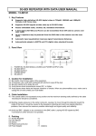
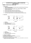
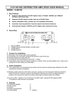
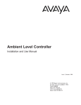
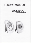
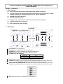
2.4GHz Digital Wireless A/V/Data Transmitter and Receiver KIT USER MANUAL MODEL: 15-2400DK 1. Key Features Offer a wireless link solution audio/video/data signals connection. 2.4 GHz frequency hopping spread spectrum module and supported max. 25 Auto hopping channels for resisting interferences to other 2.4G devices. 100mW RF output (Average). Point to point mode only. MPEG-4 (D1) standard video compression and stereo audio inputs. 5-bit ID pairing key for security. Max. 250 meters (light-of-sight) 2. Panel View 15-2400DT 1 ○ ①. ②. ③. ④. ⑤. 2 ○ 3 ○ 4 ○ 15-2400DR 5 ○ 6 ○ 7 ○ 8 ○ 9 ○ DC 12V IN: DC 12V power input. RS-485 I/O: 2-wire half-duplex RS-485 supported. AUDIO I/O: RCA female connectors for the stereo audio signal. VIDEO I/O: BNC female for the analog CVBS video signal. POWER ON or RF LINK LED: Indications Power/RF LINK LED Power On On RF Link Loss Low Flashing ⑥. RS-485 LED: Indicated to RS485 data are transmitted or received ⑦. ID Setting: ID setting is use for paring with 15-2400DK transmitter and receiver each other. It must be make a same ID code first before you setup the devices. ⑧. BAUD RATE and TERMINATION: Baud rate and 120 Ohm termination setting by DIP switch. (Note: After changing the baud rate setting by DIP switch, please re-boot the device again.) ⑨. ANT: SMA connector for connected to 2.4 GHz antennas. 1 3. Quick Installation 3.1 3.2 3.3 3.4 3.5 To set the same ID code with Transmitter and Receiver each other by 5-bit DIP switch. To set the same Baud Rate with Transmitter and Receiver each other by 2-bit DIP switch. Plug the Video and Audio signals to the BNC and RCA connectors. Plug the 2.4G Antenna to SMA connector. Please check +12VDC input, then power on the devices. REMARK: Avoid the frequency channels have the interference; please don’t close to the 802.11 a/b/g/n AP routers and other 2.4GHz devices. 4. Caution for Installation 4.1 4.2 4.3 4.4 4.5 Be careful; never let any water in this equipment. If necessary, use a soft cloth moistened with alcohol to wipe off the dust. Be extra careful not to shake the unit. Avoid places where temperatures exceed 50°C or higher. Avoid places where there are frequent vibrations or shocks. When any abnormalities occur, make sure to unplug the unit and contact your local dealer. 5. Packing 5.1 Transmitter 5.2 Receiver 5.2 Antenna 5dBi 5.3 User manual 5.4 Screws 5.5 Plastic-Conical-Anchor 5.6 Power Adaptor ×1 ×1 ×2 ×1 ×8 ×4 ×2 [Option] 6. Specification Items / Models RF Frequency Channels RF TX Power Modulation Min. RX Sensitivity RF Impedance Distance vs. Frame Rate Video Video Compression Max. Frame Rate vs. Resolution Bit Rate Audio Sampling Rate S/N Ratio Data RS-485 15-2400DT 15-2400DR 2400 ~ 2480 MHz, 25-CH Auto Hopping (FCC & CE RTTE) 100mW (Average) -16-QAM,QPSK,BPSK --80dBm 50Ω 50Ω 250 Meters: 15 ~25 fps(NTSC) / 13 ~21 fps(PAL) 150 Meters: 20 ~30 fps(NTSC) / 17~25 fps(PAL) 100 Meters: 30 fps(NTSC) / 25 fps(PAL) MPEG-4 NTSC: 30 fps at 720 × 480 (D1) PAL: 25 fps at 720 × 576 (D1) Up to 6Mbps 48KHz, Stereo 63dB 2-wire RS-485 Half Duplex Baud Rate: 2400/4800/9600 bps Fixed Formats:1 Start bit, 1 Stop bit, 8 Data Bits, No Parity 120 Ohm Termination Resistor ON/OFF Setting LED Indicators Red LED Power On and RF Link Status Green LED RS-485 Data Link Status Mechanical & Environmental Power Consumption 230 mA @ 12VDC Operation Temp. -10°C ~ 50°C Storage Temperature -30°C ~ 85°C Dimensions 118 × 75 × 25 mm (without Antenna) Weight (without antenna) 237 g 2 230 mA @ 12VDC 235 g FCC Part 15 Notice: This equipment has been tested and found to comply with the limits for a Class B digital device, pursuant to part 15 of the FCC rules. These limits are designed to provide reasonable protection against harmful interference in a residential installation. This equipment generates, uses and can radiate radio frequency energy and, if not installed and used in accordance with the instructions, may cause harmful interference to radio communications. However, there is no guarantee that interference will not occur in a particular installation. If this equipment does cause harmful interference to radio or television reception, which can be determined by turning the equipment off and on, the user is encouraged to try to correct the interference by one or more of the following measures: -Reorient or relocate the receiving antenna. -Increase the separation between the equipment and receiver. -Connect the equipment into an outlet on a circuit different from that to which the receiver is connected. -Consult the dealer or an experienced radio/TV technician for help. 1. This Transmitter must not be co-located or operating in conjunction with any other antenna or transmitter. 2. This equipment complies with FCC RF radiation exposure limits set forth for an uncontrolled environment. This equipment should be installed and operated with a minimum distance of 20 centimeters between the radiator and your body. 3. Any changes or modifications (including the antennas) made to this device that are not expressly approved by the manufacturer may void the user’s authority to operate the equipment. Q2012/02/20 3