1
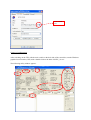
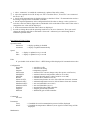
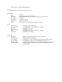
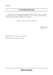
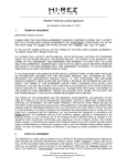
TEC
Thermo-Electrical Controller
SHORTFORM USER MANUAL
HIGH Q LASER PRODUCTION GMBH
KAISER-FRANZ-JOSEF-STR. 61
A-6845 HOHENEMS
AUSTRIA
TEL +43-5576-43040
FAX +43-5576-43050
E-MAIL [email protected]
HTTP://WWW.HIGHQLASER.CO
How to use the Thermo-Electric-Controller:
PDG back panel connections:
Make sure that the main power switch of the TEC electronic is in OFF position labelled “0” and
connected to the mains with a 3-pin power cord to ensure proper grounding.
Connect the RS232-RS422 converter to your serial PC interface COM1 and the other end to the
corresponding plug at the TEC or LC1 controller, labelled “COM”.
Connect the TEC-Cable at the TEC or LC1 controller at the plug with AUX1. Connect the other
end at the corresponding plug at the laser head.
Operate the PDG with the Windows GUI:
Communication Settings
If you use d different communication por from COM1, it is necessary to generate a link from the
NSTEC_23.exe. At the target path of the link properties you can select the port by adding “ –c2” for
COM2, “ –c3” for COM3 and so on.
select COMx
port
Change of configuration
After switching on the TEC with the main switch on the back side of the controller, start the Windows
graphical user interface (GUI) with a double-click on the label “NSTEC_23.exe”
The following utility window appears:
2.
1.
6.
3.
5.
4.
1. select “automatic” to enable the continuously update of the utility values
2. select the required device ID. If only one TEC is used the ID is 1, if two TEC’s are connected
the ID is 1 & 2.
3. check serial communication by double clicking on the label “Echo”. If communication works a
hex string is displayed next to the label “EchoStr”.
4. Set the required parameters in the configuration field. In order to change a value you have to
write the value into field 4 (figure above) and double click on the label of the value. If the value is
changed the new value will be displayed.
5. In the measurement field the actual values are displayed.
In order to change the mode the operating mode have to be set to interactive. Then you could
change the settings and click on the button “Set mode”. Afterward you could change back to
automatic operation mode.
Description of Utility Values
Operation mode
Interactive
Automatic
-> display updating is disabled
-> display is updated automatically
Speed
Fast
Slow
-> display is updated every 1 second
-> display is updated every 3 second
Echo
If you double click on label “Echo” a HEX String will be displayed if communication works
Configuration
DeviceID
Mode
Setpoint
MaxCurrent
MaxIntNTC
MaxLED
RTimer
MaxActivNTC
MinActiveNTC
MaxPassiveNTC
MinPassiveNTC
PropGain
IntgGain
DiffGain
-> actual device ID
-> actual mode setting
->temperature setpoint
-> maximal TEC current (changes only after power on/off active)
-> maximal electronic temperature (must be set to 816)
-> minimal internal supply voltage (must be set to 440)
-> internal timer (must be set to 32)
-> maximal temperature on active side of thermo electronic element
-> minimal temperature on active side of thermo electronic element
-> not used (should be set to 1023)
-> not used (should be set to 1)
-> proportional gain of PID controller
-> integral gain of PID controller
-> differential gain of PID controller
Commands
not used
Parameters
Trace
deltaT
Mathematics
-> if enabled the serial communication protocol will be displayed
-> if enabled the temperature difference (error signal of control loop) will be
displayed
Digital values of internal PID algorhyhtm
Settings
Digital value of internal electronic parameters
Measurement
Pot
IntNTC
ActiveNTC
PassiveNTC
currentHeat
currentCool
LED
-> not used
-> temperature of internal electronics
-> actual temperature of active side of thermo electronic element
-> not used
-> actual heat current
-> actual cool current
-> actual value of voltage supply of internal electronics
Mode
Control loop
Heat cool mode
Setpoint
Linearize temp
Hirez
LED mode
Error Code
No Peltier
Software Error
Active Range
Passive Range
Under Voltage
Electronic Temp
-> should be set to “closed loop”
-> setting depends on laser system (see manual)
-> should be set to “reg”
-> should be set to “no”
-> setting depends on laser system (see manual)
-> should be set to inrange
-> Peltier is not connected (check cable connection)
-> internal software timing error
-> temperature is out of range (check max min levels and setpoint)
-> (set MaxPassiveNTC to 1023 and MinPassiveNTC to 1)
-> internal supply voltage error (check MaxLED value should be 440)
-> internal electronic temperature error (check MaxIntNTC value
should be 816)