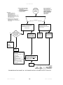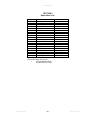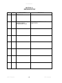
1
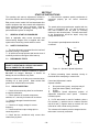
INSTALLATION OPERATION MAINTENANCE MELLTRONICS DRIVES EDDY CURRENT CONTROL MAIL: PO BOX 2368 INDIAN TRAIL, NC 28079-2368 SHIPPING: 3479 GRIBBLE ROAD MATTHEWS, NC 28104-8114 PHONE: 704-821-6651 www.melltronics.com SAFETY WARNINGS: Improper installation or operation of this drive control may cause serious injury to personnel or equipment. Before you begin installation or operation of this equipment you should thoroughly read this instruction manual and any supplementary operating instructions provided. The drive must be installed and grounded in accordance with local and national electrical codes. To reduce potential of electric shock, disconnect all power sources before initiating any maintenance or repairs. Keep fingers and foreign objects away from ventilation and other openings. Keep air passages clear. Potentially lethal voltages exist within the control unit and connections. Use extreme caution during installation and start-up. BRANCH CIRCUIT PROTECTION: Branch circuit protection is to be provided by end user. OVERLOAD PROTECTION: Overload protection must be provided per national electric code article 430, Section C. INITIAL CHECKS: Before installing the drive control, check the unit for physical damage sustained during shipment. Remove all shipping restraints and padding. INSTALLATION LOCATION OF CONTROL: Controls are suitable for most factory areas where industrial equipment is installed. The control and operator’s control station should be installed in a well-ventilated area. Locations subject to steam vapors or excessive moisture, oil vapors, flammable or combustible vapors, chemical fumes, corrosive gases or liquids, excessive dirt, dust or lint should be avoided unless an appropriate enclosure has been supplied or a clean air supply is provided to the enclosure. The location should be dry and the ambient temperature should not exceed 104oF. If the mounting location is subject to vibration, the enclosure should be shock-mounted. If the enclosure has a ventilating fan, avoid, wherever possible, and environment having a high foreign-matter content otherwise the filters will have to be changed more frequently or micron-filters installed. Should a control enclosure require cleaning on the inside, a low pressure vacuum cleaner is recommended, not an air hose, because of the possible oil vapor in the compressed air and its high pressure. MELLTRONICS 1235 – RECEIVING INFORMATION EDDY-CURRENT MODEL PART NUMBER SERIAL NUMBER REVISION HORSEPOWER RATING VOLTAGE MODIFICATIONS ACCEPTANCE: Carefully inspect shipment upon arrival and check items with packing list. Shortage or damage should be reported promptly to the carrier and your distributor. 1235 MANUAL TABLE OF CONTENTS SECTION 1 1.1 1.2 SECTION 2 2.1 2.2 2.3 2.4 2.5 START-UP INSTRUCTIONS......................................................................................................... 26 GENERAL START-UP PROCEDURE .................................................................................................................... 26 SAFETY PRECAUTION:......................................................................................................................................... 26 PRELIMINARY TESTS ........................................................................................................................................... 26 BASIC CONTROL SET-UP..................................................................................................................................... 27 EDDY CURRENT ADJUSTMENT........................................................................................................................... 27 SECTION 8 8.1 8.2 8.3 8.4 INSTALLATION............................................................................................................................. 21 DESIGN .................................................................................................................................................................. 21 CRITICAL ENVIRONMENTAL FACTORS.............................................................................................................. 21 SHIELDED CABLE ................................................................................................................................................. 21 EXTERNAL AC RELAYS ........................................................................................................................................ 21 ALLOWABLE AMPACITIES OF INSULATED COPPER CONDUCTORS .............................................................. 22 TRANSFORMERS .................................................................................................................................................. 23 CLUTCH CIRCUIT .................................................................................................................................................. 25 SECTION 7 7.1 7.2 7.3 7.4 7.5 CIRCUIT DESCRIPTION............................................................................................................... 10 POWER SUPPLY ................................................................................................................................................... 10 RUN RELAY CIRCUIT ............................................................................................................................................ 12 SPEED REFERENCE CIRCUIT ............................................................................................................................. 13 SPEED FEEDBACK CIRCUIT ................................................................................................................................ 14 ERROR AMPLIFIER CIRCUIT................................................................................................................................ 15 PHASE CONTROL CIRCUIT .................................................................................................................................. 16 POWER OUTPUT CONTROL ................................................................................................................................ 17 JOG OPTION BOARD ............................................................................................................................................ 19 FRICTION BRAKE OPTION BOARD...................................................................................................................... 20 SECTION 6 6.1 6.2 6.3 6.4 6.5 6.6 6.7 THEORY OF OPERATION.............................................................................................................. 8 DRIVE OPERATION ................................................................................................................................................. 8 OPERATION OF BASIC EDDY CURRENT CONTROL ........................................................................................... 8 SECTION 5 5.1 5.2 5.3 5.4 5.5 5.6 5.7 5.8 5.9 DESCRIPTION................................................................................................................................. 7 SCHEMATICS .......................................................................................................................................................... 7 ADJUSTMENTS........................................................................................................................................................ 7 SECTION 4 4.1 4.2 GENERAL INFORMATION ............................................................................................................. 6 STANDARD OPERATION FEATURES .................................................................................................................... 6 STANDARD SAFETY FEATURES ........................................................................................................................... 6 STANDARD ADJUSTMENTS................................................................................................................................... 6 AVAILABLE OPTIONS.............................................................................................................................................. 6 SPECIFICATIONS .................................................................................................................................................... 6 SECTION 3 3.1 3.2 INTRODUCTION.............................................................................................................................. 5 DESIGN .................................................................................................................................................................... 5 SAFETY .................................................................................................................................................................... 5 TROUBLESHOOTING .................................................................................................................. 28 TROUBLE SHOOTING PROCEDURE ................................................................................................................... 28 TEST METER ......................................................................................................................................................... 28 OSCILLOSCOPE SIGNAL TEST............................................................................................................................ 28 COMPONENT TESTING ........................................................................................................................................ 29 SECTION 9 .............................................................................................................................................................. 39 SECTION 10 REVISION HISTORY ..................................................................................................................... 40 SECTION 11 WARRANTY .................................................................................................................................. 43 MELLTRONICS -3- REV. 05/23/08 1235 MANUAL TABLE OF FIGURES Figure 1: Eddy Current Drive Schematic .................................................................................................................. 8 Figure 2: 1235 Eddy Current Control Basic Block Diagram...................................................................................... 9 Figure 3: Power Supply Circuit................................................................................................................................ 11 Figure 4: Run Relay Circuit ..................................................................................................................................... 12 Figure 5: Speed Reference Circuit.......................................................................................................................... 13 Figure 6: Speed Feedback Circuit .......................................................................................................................... 14 Figure 7: Error Amplifier Circuit...............................................................................................................................15 Figure 8: Phase Control Circuit ...............................................................................................................................16 Figure 9: Power Output Circuit................................................................................................................................ 17 Figure 10: Bridge and Coil Current Conduction (L1+, L2 -) .................................................................................... 18 Figure 11: Bridge and Coil Current Conduction (L1-, L2 +) .................................................................................... 18 Figure 12: Jog Option Board ................................................................................................................................... 19 Figure 13: Friction Brake Option ............................................................................................................................. 20 Figure 14: Basic Drive Operator Control Interconnections ..................................................................................... 21 Figure 15: AC DC Relays........................................................................................................................................ 23 Figure 16: Operator's Speed Adjustment................................................................................................................ 26 Figure 17: Temporary Jumper - Gate to Anode ...................................................................................................... 28 TABLE OF TROUBLE SHOOTING CHARTS TROUBLESHOOTING CHART 1: DRIVE FAILS TO START ................................................................................ 30 TROUBLESHOOTING CHART 2: DRIVE SPEED UNSTABLE............................................................................. 31 TROUBLESHOOTING CHART 3: SPEED REGULATION NOT WITHIN SPECIFIED LIMITS ............................. 31 TROUBLESHOOTING CHART 4: MAXIMUM SPEED POT NOT ABLE TO CAUSE TOP SPEED OF DRIVE.... 31 TROUBLESHOOTING CHART 5: DRIVE RUNS TO FULL SPEED NOT UNDER CONTROL ............................ 32 TROUBLESHOOTING CHART 6: MAX SPEED POT NOT CAPABLE OF SETTING SPEED LOW ENOUGH ... 33 TROUBLESHOOTING CHART 7: JOG OPTION – WILL NOT JOG – RUNS OK................................................. 33 TROUBLESHOOTING CHART 8: POWER SUPPLY............................................................................................. 34 TROUBLESHOOTING CHART 9: RUN RELAY CIRCUIT..................................................................................... 35 TROUBLESHOOTING CHART 10: SPEED REFERENCE CIRCUIT .................................................................... 36 TROUBLESHOOTING CHART 11: ERROR AMPLIFIER & FEEDBACK CIRCUIT .............................................. 37 TROUBLESHOOTING CHART 12: SCR PHASE CONTROL & POWER OUTPUT CIRCUITS ........................... 38 MELLTRONICS -4- REV. 05/23/08 1235 MANUAL SECTION 1 INTRODUCTION This operating and maintenance manual contains necessary information for normal installation, operation and maintenance of Eddy Current Control Model 1235. The Operator and/or Maintenance Personnel should have access to a copy of this Instruction Book. 1.1 DESIGN Eddy Current Drives utilize a design to maximize electronic response and operational efficiency. Compact rugged physical (solid state) construction allows control and drive to be located in adverse environments with reliable operation. The purpose of this book is to provide basic operating and technical information applicable to the Eddy Current 1235 Control. It does not cover all details or variations in this equipment and should be applied in conjunction with specific schematics, drawings and engineering advice provided by Melltronics. 1.2 SAFETY Multiple safety features protect the control and associated equipment from possible damage due to drive overload, line loss, transients and other electrical or mechanical failure. Normal operator adjustments are located on isolated front panel to reduce hazards of possible electrical shock when system requires adjustment. MELLTRONICS -5- REV. 05/23/08 1235 MANUAL SECTION 2 GENERAL INFORMATION Follower operation capable of following tachometer, generator or external voltage signal reference at an adjustable ratio Current limit – AC motor current Torque control regulation Zero speed detector Auto/manual selection Phase limit Dancer position Dancer trim Adjustable acceleration, deceleration Differential speed trip Operations may be incorporated in combinations to suit applications. 2.1 STANDARD OPERATION FEATURES 1. Same basic low-cost control for all drive models 1 to 900HP 2. Compact 8” x 10” panel with single, printed circuit board construction 3. Net flexibility – many modular modifications possible with simple terminal connection installation 4. Encapsulated SCR power cube provides reliability and simplicity 5. Integrated circuit operational amplifier for high gain, fast response 6. Adjustable linear acceleration rate from 2 to 20 seconds supplied as standard 7. 2% regulation from standard AC tachometer feedback 2.2 1. 2. 3. 4. 5. 2.5 SPECIFICATIONS HP Range Eddy Current Model 1235-1 ¾ -150 1235-45 150-900 STANDARD SAFETY FEATURES Mov line transient SCR protection “RC” SCR Protection Isolated reference circuitry (except in torque mode) Fused AC Overload Protection Isolated Control Circuitry INPUT TOLERANCE Line voltage variations should not exceed –5% to +10% Frequency limitations 60HZ ± 2HZ 2.3 STANDARD ADJUSTMENTS P1 - Accel P2 - Min Speed P3 - Max Speed P4 - Meter Calibration P5 - Stability P6 - Lead P7 - Gain P8 - Bias ALTITUDE Up to 3300 feet. Consult factory for higher elevations. AMBIENT TEMPERATURE 10OC-40OC PERFORMANCE CHARACTERISTICS Linear Acceleration 2-30 seconds (Extended time optionally available) 2.4 AVAILABLE OPTIONS The standard drive may be easily modified with simple terminal connection installation. Options Include: Jog at independent adjustable jog speed Brake power supply Threading at present level Test meter MELLTRONICS VAC 115 115 SPEED REGULATION Internal AC Tachometer-2% of top speed DC Tachometer 5PY ½% regulation w/95% load change, 1% drift BC42 ½% regulation w/95% load change, 1% drift BC46 1% regulation w/95% load change DIGITAL REGULATION .05% of set speed over 10 to 1 speed range -6- REV. 05/23/08 1235 MANUAL SECTION 3 DESCRIPTION The 1235-1 Eddy Current Speed Control Printed Circuit Board Contains the following circuitry: a. Power supply b. Run relay c. Speed reference d. Speed feedback e. Error amplifier f. Phase control g. SCR power output h. Jog option board i. Friction brake option board 3.1 SCHEMATICS 1235-1 Eddy Current Control 1235-45 Eddy Current Control (High Power) 1235-6 Brake Option 1235-7 Jog 1235-15 Dancer Feedback 1235-18 Threshold Detector 1235-19 Accel Mechanical Drives ED-80, 160 ED-320, 640, 1280, 4500 3.2 ADJUSTMENTS P1 - Accel P2 - Min Speed P3 - Max Speed P4 - Meter Calibration P5 - Stability P6 - Lead P7 - Gain P8 - Bias MELLTRONICS -7- REV. 05/23/08 1235 MANUAL SECTION 4 THEORY OF OPERATION 4.1 DRIVE OPERATION An Eddy Current drive system consists of AC Motor and Eddy Current coupling, a control and operator’s control station. 4.2 OPERATION OF BASIC EDDY CURRENT CONTROL The control is used to regulate speed of the output member of the eddy current drive unit. The control supplies regulated DC excitation to the magnetic drive field coil. Drive excitation determines drive speed. Speed regulation is accomplished by comparing signals which represent actual and desired speed. The resultant error is used to produce an increase or decrease in drive excitation until actual speed equals desired speed. The drive unit consists of an AC induction motor driving the input member or fan pole assembly of the magnetic drive. There is no mechanical linkage between input and output members of the drive. Torque is transmitted from the AC motor to the load by eddy current action when the clutch field coil is excited with DC current. (Figure 1) The control supplies DC voltage to the drive field coils and automatically varies drive excitation to maintain desired speed, torque, tension, position, or horsepower, as determined by the feedback signal. The regulator section of the control maintains drive speed constant with feedback signal approximately equal to reference signal. The basic regulator consists of a reference, feedback, stabilization circuitry and a power module. The associated operator’s controls are those necessary for the operator to control the drive such as: START and STOP pushbuttons and SPEED. (+) COIL (-) 1235-1 CONTROL INPUT FAN AND POLE ASSEMBLY OUTPUT ROTOR COIL Figure 1: Eddy Current Drive Schematic MELLTRONICS -8- REV. 05/23/08 MELLTRONICS -9- OPERATORS SPEED ADJUSTMENT REF SUPPLY MIN SPEED K1 (+) (-) BIAS -15V ACCEL CIRCUIT TACH FILTER AC TACH BRIDGE MAX SPEED LOAD L2 L1 TACH + T2 CLUTCH COIL ERROR AMP STABILITY SUMMING POINT LINE FUSE 15A EC COUPLING + LEAD GAIN +30VDC +15VDC COMMON -15VDC -30VDC POWER CUBE Control Power Supply K2 T1 SCR PHASE CONTROL FIRING CIRCUIT AC MOTOR POWER 1235 MANUAL Figure 2: 1235 Eddy Current Control Basic Block Diagram REV. 05/23/08 1235 MANUAL SECTION 5 CIRCUIT DESCRIPTION 5.1 POWER SUPPLY 5.1.1 OPERATION The low voltage power supply converts 115VAC to unregulated ±30 and ±15 zener regulated DC voltage when 115 VAC is applied to the incoming line and K1 (run relay) is de-energized and no external load. 5.1.2 FUNCTIONAL DESCRIPTION Transformer (T2) reduces 115VAC line voltage on the primary to 40 volts AC across 3 to 6 on the secondary. Connections 4 and 5 provide a center tapped secondary connection. WO6 rectifier provides full wave rectification of the secondary AC voltage. Filter capacitor C1 has its positive terminal as common, the volts AC from centertap to 3 and 6 provide a voltage of 21VAC RMS. Since the peak of a 21VAC waveform is approximately 30 volts, the voltage on C1 negative terminal relative to common will be approximately 30 volts. This occurs as C1 charges to the peak value of the wave. Filter capacitor C2, the negative 30 volt supply, is similar to the positive supply except that C2 charges through diode D1. At the anode of D1, an unfiltered DC voltage appears. This voltage is used to synchronize the phase control circuit with the AC line crossing. MELLTRONICS Regulated +15 volt supply, zener diode and resistor and capacitor C16 compose the supply. The zener diode, DZ1, is a 15V ±5% unit. Current for the load and zener is supplied from the +30V unregulated supply through R2. Capacitor C16 provides additional smoothing of the regulated supply and provides a low impedance bypass of the supply. Regulated -15VDC volt supply zener diode and resistor and capacitor C17 compose the supply. The zener diode, DZ2, is a 15V ±5% unit. Current for the load and zener is supplied from the -30V unregulated supply through R3. Capacitor C17 provides additional smoothing of the regulated supply and provides a low impedance bypass of the supply. Varistor provides the power supply and its load with protection form over-voltage and from high voltage short duration spikes which are common in industrial environments. RC1 provides a low impedance shunt path for fast rising noise and high voltage spikes. - 10 - REV. 05/23/08 1235 MANUAL VARISTOR 115VAC RC1 D E +15 V +30 V 120VAC 1 T2 -15V F -30V Y 3 2 4 D1 E2 5 (-) +30 V +24 V 6 (+) WO6 R2 (+) DZ1 C1 R3 DZ2 (-) (-) (-) C2 (+) C16 SYNC SIGN AL (+) (+) 0 -15V D 30V DC COMMON +15 V REGUL ATED TO PH ASE CONTR OL CIRCU IT Figure 3: Power Supply Circuit MELLTRONICS - 11 - REV. 05/23/08 1235 MANUAL CUSTOMER AU X. CONTACT ON MOTOR STARTER 2 115VAC (11) A F MOTOR THER MAL (IF USED ) C3 STOP (L2) K1 (9) 4 RUN AC C OMMON S 5 (5) (13) K1 (14) 3 G 1 -30V K1 (10) K1 (9) TO JOG PU SH BUTTON IF U SED 9 (6) D2 E2 DC COMMON (1) D2 G K2 (2) (2) K3 K4 AC C ONTACTOR (5) (5) AMPL IFIER RATE CIRCU ITS CLAMP REL AYS Figure 4: Run Relay Circuit 5.2 RUN RELAY CIRCUIT 5.2.1 OPERATION The auxiliary contact of the AC motor starter is connected from terminal 2 to 5 on terminal board #1. This prevents over-regeneration of the clutch coil If the control should be started without the AC motor running. If a drive over-temperature switch is used, connect in series with auxiliary contact as shown. Other remote normally-closed stop push-buttons may be in series with stop push-button (PB) if desired. Start when run PB is pushed 115VAC is applied to relay K1 through auxiliary of motor starter, stop normally-closed PB contact, run PB, normally-open contact. When run PB is released, relay K1 normally-open contact (9) – (5) which closed across run normallyopen, PB maintains K1 relay energized. Relay K1 normally-open contact (10) – (6) connects relays K2, K3 and K4 across 30VDC through diode D2. Relay K1 applies AC to the power bridge. (See SCR Power Output Control Circuit.) Relays K3 and K4 open their normally-closed contacts which unclamp the amplifier dynamic compensation capacitors. MELLTRONICS K1 contact (9) – (5) also applies -30V to the speed reference circuit. (See description of Speed Reference Circuit.) When auxiliary contact of starter opens, or stop pushbutton is pushed, 115VAC is removed form relay K1, K2, K3 and K4 drop out and the AC is removed from the power bridge. The capacitors in the amplifier circuit are discharged. The ramp capacitor C4 is discharged and the reference voltage is removed from the speed pot. If the Jog option is used, the normally open jog pushbutton is connected from 9 of the control terminal strip #1 to 1 on the jog option board. The jog push-button receives no power at customer connection pin number 9 unless: 1. Starter is closed, 2. Stop Push-button not depressed, 3. Thermal switch (if used) closed and 4. If the run circuit (K1) is not latched in. (See Jog Option description.) - 12 - The relays K2, K3 and K4 are energized through terminal G which is connected to the jog option board. (See Jog Option description.) REV. 05/23/08 1235 MANUAL -30V P1 ACCEL RATE -30V R5 (10) +15V -15V K1 (6) -30V D2 Q1 R8 R4 OPERATOR SPEED ADJUSTMENT R6 DZ3 6 C Q4 D3 Q2 A D B 7 Q3 R10 P2 MIN SPEED E (11) K1 R9 (3) 8 C4 R7 +15V COMMON CW H TO ERROR AMPLIFIER (L1) INPUT OR JOG OPTION BOARD Figure 5: Speed Reference Circuit 5.3 SPEED REFERENCE CIRCUIT 5.3.2 5.3.1 OPERATION With relay K1 de-energized normally-open contact (10)-(6) open, normally-closed contact (11)-(3) closed, speed pot fully clockwise. ABCDE- Approximately Zero Approximately plus (+) 0.5V Approximately Zero (0) Approximately Minus (-) 0.5V Approximately Zero (0) With relay K1 energized: A- Minus (-) 10V ±5% B- Approximately voltage at [A] Minus (-) 0.5 V or approximately minus (-) 9.5V C- Ramping to approximately same as A D- Ramping to approximately same as C plus (+) 0.5V or minus 10.5V E- Ramping to approximately same as A MELLTRONICS FUNCTIONAL DESCRIPTION OF OPERATION With K1 relay de-energized or speed potentiometer turned down, voltages at [A] and [C] are zero and nearly equal. Current flowing through Q1 is diverted through D3 and R6. The emitter follower Q2, provides a low impedance sink for this current. The Q2 B-E voltage is cancelled approximately by the forward drop of D3. K1 relay closure provides current for zener diode, DZ3, and the speed potentiometer through R4 from the minus (–) 30V unregulated supply. The reference voltage at terminal #6 provided by DZ3 will be –10V ±5%. As voltage is applied to A, the current from Q1 which was diverted from charging C4 now charges C4. The current is diverted into D3 when C4 reaches a voltage approximately equal to A. - 13 - REV. 05/23/08 1235 MANUAL Transistors Q3 and Q4 serve as a tandem emitter follower, providing a high impedance input to C4 negative, at the same time providing drive for the current input to the regulator, as well as other regulators or ratio potentiometers for other optional regulators. Potentiometer P1 controls the charging rate of C4 by setting the current through Q1. When K1 relay de-energizes, a normally-closed (N/C) contact, (3 and 11) closes, to quickly discharge C4 through R10 . REMOVE JUMPER FOR 3600 RPM 10 O OPTIONAL DC TACH 11 (+) AC TACH D5 D4 R15 D6 R16 D7 12 (-) P R17 R18 SUMMING JUNCTION TO ERROR AMPLIFIER (L1) P8 13 C9 C10 CW 14 R19 (+) SPEED METER 0-100µA P4, METER CALIBRATOR (-) 15 Figure 6: Speed Feedback Circuit 5.4 SPEED FEEDBACK CIRCUIT 5.4.1 OPERATION Full-wave bridge rectifier diodes D4 through D7 rectifies AC tachometer voltage to DC. This voltage is applied to R15, R16 and R17 in series. Capacitor C9 and C10 provide filtering for the feedback signal. NOTE: WHEN AN 1800RPM DRIVE IS USED, R18 IS JUMPERED OUT. Since the summing junction of the error amplifier is at virtual ground the current is: MELLTRONICS = I fb Voltage at 10 R15 + R16 + R17 This current is the speed feedback current. DC tachometer may be connected as shown above in place of an AC tachometer. SPEED METER Current for the speed meter is provided through R19 and meter calibrate potentiometer P4, supplied by the rectified AC tachometer voltage (or DC tachometer voltage). - 14 - REV. 05/23/08 1235 MANUAL K3 (1) R31 (4) I K4 (4) I REFERENCE STABILITY P5 STABILITY A NEGATIVE REFERENCE FROM SPEED REFERENCE CIRCUIT (H) OR SEE OPTION BOARD C8 C5 (-) R11 P3, 15K MAX SPEED R12 (+) CW R15 O R18 R21 N914 C10 C4 (-) (+) P R17 R16 C7 CW P6 FEEDBACK POSITIVE SPEED FEEDBACK (-) REMOVE JUMPER FOR 3600RPM I R32 (+) 2 D8 D9 B C11 L1 I 6 3 GAIN TO PHASE CONTROL CIRCUIT 7 4 R20 -15V +15V P7 CW DC COMMON P8 R3 K I BIAS J -15V Figure 7: Error Amplifier Circuit 5.5 ERROR AMPLIFIER CIRCUIT 5.5.1 OPERATION The voltage at [A], i.e bias potentiometer counterclockwise, is generated by the output of the speed reference circuit, or if the jog option is used, is generated by the potentiometer across the minus (-) power supply. (See description of Jog Option Board.) The voltage at [B] with voltage [A] is approximately zero at a level from minus (-) 0.5 to slightly positive. As speed reference voltage is applied to [A] the output of L1 operational amplifier (See Figure 7) rises to a positive voltage at about 10 volts the phase controller will turn on the SCR’s. As the drive coil is excited, torque is transmitted to the load and rotation of the output shaft and the tachometer occurs. Increasing the gain with P7, requires that less current be supplied by the speed feedback circuit, the drive speeds up. With higher gain a small change in speed, say due to drive loading, produces a greater change in error amplifier L1 and the SCR output. Potentiometers (lead p6) and (stability P5) provide a means for matching the dynamics of the control to the drive and load. Maximum speed (P3) ratios the value of reference current to the current obtained by the feedback generator and feedback circuit. Since the various feedback voltages may represent maximum speed of the drive and the volts per RPM ratio of tachometers vary. The speed feedback current reduces the output of L1 and the SCR output and equilibrium is reached where the drive speed is proportional to the voltage at [A]. MELLTRONICS - 15 - REV. 05/23/08 1235 MANUAL BIAS ADJUSTMENT P8 Since the input signal at [A] may be produced at a very long rate, say 40 seconds or .25V per second, the offset in L1 may require a few seconds to get L1 up to a voltage where the phase controller will fire the SCR’s. Bias adjustment will raise the amplifier L1 output up to nearly the “firing point”. At this level, a small reference input will “fire” the SCR’s and hesitation with long-range inputs is eliminated. Relays K3 and K4, normally-closed contacts remove the charge from the capacitors used to obtain dynamic compensation. Relays K3 and K4 de-energize when the line contactor K2 opens. (See Line Contactor Circuit description.) +15V R25 R26 R14 R13 R30 DZ4 R24 ERROR AMPLIFIER P2 R23 1 Q5 2 L1 D11 Q6 T1 PULSE TRANSFORMER C13 C12 DC COMMON Figure 8: Phase Control Circuit 5.6 PHASE CONTROL CIRCUIT 5.6.1 OPERATION Transistor Q5 operates to discharge the timing capacitor each time the AC line goes through zero. When the line is not near zero the negative unfiltered full wave DC voltage reverse biases the base emitter junction of Q5. Q5 turns off and C13 is able to charge. When the AC line crosses zero, the negative voltage becomes zero. Transistor Q5 becomes forward biased, with the base current supplied by the +15V supply through R26. Each time the line crosses zero, Q5 turns on to discharge C13. Capacitor C12 provides a shunt path for noise which may cause false “firing” of Q5. MELLTRONICS Diode D11 conducts when Q5 base emitter junction is reverse biased. This prevents breakdown conduction of the B-E junction. After each line crossing, C13 is able to charge from the +15V regulated supply, through R14. Unijunction Transistor Q6 provides a means of providing an SCR trigger as a function of the time after line crossing. On a 60HZ line a timing period begins every 8.3 milliseconds. If the capacitor C13 reaches the trigger voltage of the unijunction, C13 will discharge through the primary of T1 and the SCR’s will be fired. - 16 - REV. 05/23/08 1235 MANUAL The charging rate of C13 is controlled by the output of the error amplifier. When the input is negative or low positive, C13 does not receive enough current to charge it to the trigger level in 8.3 milliseconds. The charging current normally through R14 and R13 in series with R24 is diverted through zener DZ4. As the DC input rises, further positive, C13 will charge at a faster rate and will reach the trigger voltage of the unijunction before 8.3 milliseconds have elapsed. When this happens the SCR, which is forward biased at that time, will be fired. TB1 7 A K2 L1 L1 115 VAC L2 1FU 1 7 10 2 R RECTIFIER BLOCK L2 A 3 11 C3 S A S C CLUTCH S C2 (-) 4 (+) G1 6 G2 12 5 RC4 R1 13 14 RC2 RC3 V W X 5 T1 6 3 4 Figure 9: Power Output Circuit 5.7 POWER OUTPUT CONTROL 5.7.1 OPERATION With K2 contact closed, 115VAC is applied to the full wave SCR bridge. With pulses applied to the SCR gates (See Figure 8) DC is applied to the clutch coil. A pulse transformer isolates the SCR output circuit from the rest of the control. MELLTRONICS Conduction from the AC line through the bridge and clutch coil when L1 is positive relative to L2 is illustrated in Figure 10. - 17 - REV. 05/23/08 1235 MANUAL (+) 1FU L1 (CLOSED) C1 CLUTCH (-) L2 C2 Figure 10: Bridge and Coil Current Conduction (L1+, L2 -) Conduction from the AC line through the bridge and clutch coil when L2 is positive relative to L1 is illustrated in Figure 11. Resistors RC2, RC3 and RC4 provide a low impedance shunt path for noise and line spikes which are prevalent in industrial environments. Resistor R1 provides a minimum SCR current. Without this resistor the SCR may not conduct because the inductive load (clutch) may not allow holding current to be attained during the duration of the gate pulse. A voltage suppressor provides over-voltage protection for the rectifier block. (-) 1FU L1 (CLOSED) C1 CLUTCH (+) L2 C2 Figure 11: Bridge and Coil Current Conduction (L1-, L2 +) MELLTRONICS - 18 - REV. 05/23/08 1235 MANUAL I -15V F H 1235-7 JOG OPTION PC BOARD H F Q1 JA ZZ (4) WW JA (10) JA (11) JA (12) YY (6) G JA (R) JA (7) (8) -30V XX R28 Y P&B 115VAC (13) CW P8 JOG SPEED JA C15 (4) AC COMMON S (1) M R29 (9) SIGNAL COMMON JA M TB4 2 1 3 (+) (-) SELECT CAP TO MODIFY JOG ACCEL RATE IF DESIRED RATED 15 VOLTS OR HIGHER TO TB1 PIN 9 JOG Figure 12: Jog Option Board 5.8 JOG OPTION BOARD 5.8.1 OPERATION When jog option board is used the normal jumper connection between the output of the ramped reference H and the input to the error amplifier circuit I is opened and reconnected through H and I of the jog option board. When JA relay energizes a negative voltage is applied to the input of the error amplifier through the max speed potentiometer P3 and resistor R11. The connection to the ramp generator output is opened. MELLTRONICS Normally open contact of JA (12)-(8) connect K2-K3 and K4 to –24VDC at Y. The function of these relays is the same as described (Figure 4). Jog relay JA is inoperative when relay K1 (run relay) is energized, when Jog button is connected between TB4, terminal 1 and TB2, terminal 9. If desired, the rate of acceleration to the jog speed may be modified by placing a capacitor, 15V rating or more, as shown in Figure 12. - 19 - REV. 05/23/08 1235 MANUAL A C B (7) BCR (2) 115VAC (+) (-) WO6 (5) BCR (8) (1) BCR (4) C14 R27 TB3 1 2 3 BRAKE 90V (750 ma MAX) Figure 13: Friction Brake Option 5.9 friction brake. When K2 energizes relay BCR N/C contacts open and the friction brake is released. FRICTION BRAKE OPTION BOARD 5.9.1 OPERATION Wires A, S and C are connected to the main board to corresponding letters. When K2 is energized and the main control deenergized, 90VDC (approximately) is applied to the MELLTRONICS This option is for a voltage engaged brake. Other brake options are available for voltage (AC or DC) released brakes (fail-safe) and for applying a variable DC voltage to the brake. - 20 - REV. 05/23/08 1235 MANUAL SECTION 6 INSTALLATION 6.1 DESIGN The enclosure is designed for either floor or wall mounting depending on customer and horsepower requirement. The control should be installed in a well ventilated area. Unless designed for special conditions, the enclosure cabinet should be located using the following criteria. 6.2 CRITICAL ENVIRONMENTAL FACTORS o Ambient Temperature should not exceed 104 F o (40 C). Ambient Temperature should not fall below 50oF (10oC). Enclosure’s circulating air should be clean, dry and free from flammable or combustible vapors, corrosive gasses, solids or liquids. Enclosure should be shock mounted if location is subject to vibration. Enclosure doors should have clearance to allow easy access to controls for inspection and maintenance. WARNING: EXTREME CARE MUST BE EXERTED DURING THE DRILLING AND/OR CUTTING PHASE WHEN INSTALLING ELECTRICAL CONDUIT. CARELESSNESS WILL CAUSE CHIPS AND PIECES OF METAL TO FORM SHORT CIRCUITS AND WILL RESULT IN NON-WARRANTY DAMAGE. 6.3 SHIELDED CABLE To avoid stray signal interference provide Belden #8208 2 conductor and/or #8771 3 conductor shielded cable or their equivalents when interconnecting with: Speed potentiometer Jog potentiometer AC and DC tachometers Speed Indicators Ammeters The shield should be connected AT ONE POINT ONLY. This point is at common, not earth or chassis ground, unless otherwise shown on schematic. To avoid stray signal interference, DO NOT run reference signal interconnecting wires in the same conduit or in close proximity to power wiring. Armature leads and tachometer cable is to be routed separately for best operation. Keep wire length as short as possible. 6.4 EXTERNAL AC RELAYS When external customer AC and DC relays are connected to control, adequate suppression networks are suggested across relay coil. Arc suppression networks (See Figure 15) prevent signal “noise” and extend life of relay contacts. Specific installation should be reviewed by a qualified engineer. Figure 14: Basic Drive Operator Control Interconnections MELLTRONICS - 21 - REV. 05/23/08 1235 MANUAL 6.5 ALLOWABLE AMPACITIES OF INSULATED COPPER CONDUCTORS Not more than 3 conductors in raceway or cable or direct burial based on ambient temperature of 30oC, 86oF. Size Temperature Rating of Conductor o o o 75 C 85 C 90oC 110oC 125oC 200oC 250oC AWG 60 C o o o o o o o MCM (140 F) (167 F) (185 F) (194 F) (230 F) (257 F) (392 F) (482oF) Types Types Types Types Types Types Types Types RUW RH, V, TA, AVA, A1 A TFE (14-2), RHW, M1 TBS, AVL (14-8), (14-8), (Nickel T, RUH SA, AA, AA, or TW (14-2), AVB, FEP** FEP* nickelTHW, S1S, FEPB* coated THWN, FEP, copper XHHW FEPB, only) RHH, XHHW** THWN 14 15 15 25 30 30 30 30 40 12 20 20 30 30 35 40 40 55 10 30 30 40 40 45 50 55 75 8 40 45 50 50 60 65 70 95 6 55 65 70 70 80 85 95 120 ***4 70 85 90 90 105 115 120 145 ***3 80 100 105 105 120 130 145 170 ***2 95 115 120 120 135 145 165 195 ***1 110 130 140 140 160 170 190 220 ***0 125 150 155 155 190 200 225 250 ***00 145 175 185 185 215 230 250 280 000 165 200 210 210 245 265 285 315 0000 195 230 235 235 275 310 340 370 250 215 255 270 270 315 335 300 240 285 300 300 345 380 350 260 310 325 325 390 420 400 280 335 360 360 420 450 500 320 380 405 405 470 500 600 355 420 455 455 525 545 700 385 460 490 490 560 600 750 400 475 500 500 580 620 800 410 490 515 515 600 640 900 435 520 535 555 1000 455 545 585 585 730 680 1250 495 590 645 645 1500 520 625 700 700 785 1700 545 650 735 735 2000 560 665 775 840 775 WARNING: NO TERMINAL POINT IN THE CONTROL SHOULD BE EARTH GROUNDED EXCEPT WHERE SUCH GROUNDING IS EXPLICITLY SHOWN ON DRAWING. MELLTRONICS - 22 - REV. 05/23/08 1235 MANUAL 2. TEST POINT EE (NO RUN OR JOG) V+ AC C OIL Capacitor C13 charges. This is not sufficient to fire Q6 before the next synchronizing pulse arrives. NOTE: Output error amplifier L1 will be approximately zero volts. VDC COIL Figure 15: AC DC Relays 6.6 TRANSFORMERS Transformers shall be connected to conform with data on the transformer nameplate to obtain correct voltage for input to control. 8V 0V 8.3 µs NOTE: SCOPE REFERENCE (COMMON) TO TB113 UNLESS OTHERWISE INDICATED. 6.6.1 TEST POINTS 1. (-)WO6 or (Cathode D1) 4. TEST POINT EE, DRIVE IN RUN OR JOG Low clutch voltage, 10 volts Note: Output of L1 positive approximately 5 volts. Q6 fires at indicated peaks. Negative going full-wave rectified waveform used to synchronize phase control circuit. 8.3 µs 13V 0 30V 0V 8.3 µs 2. BASE Q5 5. TEST POINT EE, DRIVE IN RUN Positive pulse at base of Q5 turns on transistor Q5 to discharge timing capacitor C13 each time line goes to zero volts, synchronizing C13 to line. High clutch voltage, 75 volts. Note: Output of L1 positive approximately 12 volts. Q6 fires each time charge on C13 reaches 13 volts. (First pulse turns on the SCR, the rest have no effect.) 13V .6 V 0 .6 V 8.3 µs 0V 8.3 µs MELLTRONICS - 23 - REV. 05/23/08 1235 MANUAL 6. B2 of Q6, DRIVE IN RUN Low clutch voltage, 10 volts. Sharp pulses coincide with Q6 firing presented in (4). 50V 0V 15V 8. Clutch voltage, 75VDC 0V Same hook-up as (8). Drive condition same as (5). 8.3 µs 7. B1 of Q6 Same conditions as in (6). Firing pulses on primary of T1 (pulse transformer). 165V 0V 0 6.6.2 WARNING THE FOLLOWING WAVE FORMS ARE REFERENCED TO THE AC LINE OR CLUTCH CIRCUIT (AS SPECIFIED). THE SCOPE COMMON MUST BE ISOLATED FROM THE AC LINE (POWER TO SCOPE) AND NOT TOUCHING GROUND IN ANY WAY. DO NOT TOUCH THE SCOPE LEADS OR CASE AND GROUND AT THE SAME TIME. HAZARDOUS VOLTAGES MAY BE PRESENT BETWEEN THE SCOPE AND GROUND. 8. CLUTCH VOLTAGE, 10VDC Scope connected across clutch, common to C2. Probe to C1. Drive condition same as (4). RESISTANCE MEASUREMENTS NOTE: POLARITIES ON RESISTANCE READING INDICATE POLARITY OF TEST VOLTAGE (FROM OHMMETER) APPLIED TO TERMINAL UNDER TEST. CHECK POLARITY OF TEST VOLTAGE OF OHMMETER USED BEFORE ATTEMPTING TESTS. RECOMMENDED METER -- SIMPSON 260. (+) Positive terminal is positive in ohms position with switch in +DC position. (-) Common, terminal is negative. Changing switch to -DC position reverses test voltage at terminals: (+) Positive terminal is negative. (-) Common, terminal is positive. This meter allows the use of this switch to reverse the test voltage. Other meters, without this feature will require reversal of the test leads at the points under test. MELLTRONICS - 24 - REV. 05/23/08 1235 MANUAL Remove ALL POWER from circuits when making Resistance measurements. Approximate readings indicate readings depend on non-linear elements such as diodes, transistors, etc. Large capacitors also cause some readings to deviate from stated resistance readings. A capacitor will cause the initial resistance to read zero ohms, then increase to some minimum value as stated. The rate at which the resistance increases depends on the size of the capacitor, resistances in the circuit and meter and current supplied by the meter to charge the capacitor. 10. 11. 12. 13. 14. +50K (- 200ohms) +50K (- 200ohms) +50K (- 200ohms) +10 ohms or less Greater than 100K 6.7 CLUTCH CIRCUIT (no external connections to L1, L3, L1 and L2) Meter +Lead To C1 -Lead To C2 + 1K—400 ohms Connect Meter common to TB2-15 C1 C2 ∞ NOTE: NO EXTERNAL CONNECTIONS ON TB1 OR TB2. C2 C1 +600 ohms (R1 removed) C1 L1 Both directions (R1 removed) (SCR resistance) C1 L2 Both directions (R1 removed) (SCR resistance) C2 L1 + 600 ohms – (Bridge Diode) (R1 removed) C2 L2 + 600 ohms – (Bridge Diode) (R1 removed) PINREADS 1. ∞ (Infinity) 2. ∞ 3. ∞ 4. ∞ 5. ∞ 6. +1K (- 30K) 7. +47K 8. 0 to 1K, depends on min speed pot setting ∞ 9. MELLTRONICS - 25 - (R1 removed) REV. 05/23/08 1235 MANUAL SECTION 7 START-UP INSTRUCTIONS The operating and start-up adjustments outlined in this section describe the normal operating procedure. Eddy current control model 1235 and associated drive system equipment has been tested and subjected to quality control inspection prior to shipment. However, visual inspection and preliminary testing must be performed before system is energized. 7.1 GENERAL START-UP PROCEDURE Refer to applicable eddy current schematic and interconnecting diagram that is supplied with each system when connecting control and drive motor. 7.2 7. Check that the operators speed potentiometer is connected properly per the control connection diagram. The speed reference potentiometer supplied with the control is S/N 990-35, 5K, 1 W, with a minimum of 500 volts insulation from the shaft (or mounting surfaces) to the electrical parts. The lead connections at the potentiometer should be taped, using high voltage insulation tape. The operator’s speed adjustment should be connected. SAFETY PRECAUTION: C - LEAD 1. The drive will remain uncoupled from the load until preliminary testing is completed. 2. All personnel except operator shall remain clear of machinery and drives throughout initial start-up. G OH MMETER SHOR T 7.3 PRELIMINARY TESTS WARNING: PRIOR TO RESISTANCE CHECKS, DISCONNECT ALL AC POWER TO THE CONTROL. + LEAD A Figure 16: Operator's Speed Adjustment Use an ohmmeter to measure resistance to ground. DO NOT use Megger, Bellringer, or Buzzer as damage to semi-conductors may result. 8. Before proceeding insure start/stop circuitry is functional before attempting to rotate motor. Measure resistance on all eddy current terminal strips, including coil to earth ground. Meter should read greater than 100,000 Ohms at all points. Control and Adjustment Location Operator’s Station 7.3.1 a. Run push-button (green), energizes relay K1 b. Stop push-button (black), de-energizes c. E-Stop d. Operator’s Speed adjustment position of adjustment determines motor speed. Clockwise increases speed. VISUAL INSPECTION 1. Check all interconnecting wires for conformance to supplied schematics. 2. Check operation of movable components, switches, etc., manually for freedom of movement. 9. If a DC tachometer is used for feedback, place a DC voltmeter (+) positive lead on customer terminal strip #10 and (-) negative lead on terminal #13 and rotate drive in the normal running direction. 3. Check for damaged internal wires and components. 4. Check for AC supply voltage for correct frequency. The voltmeter will measure positive voltage when the tachometer is correctly connected. 5. Check transformer output voltage prior to connecting to drive. 6. Check that the mechanical eddy current drive rotates freely by hand. MELLTRONICS - 26 - REV. 05/23/08 1235 MANUAL 7.4 BASIC CONTROL SET-UP 1. Operator’s Control Station Set speed potentiometer fully counterclockwise 2. 1235 control printed circuit board set controls: Minimum speed P2 fully counterclockwise Maximum speed P3 fully counterclockwise Bias P8 fully counterclockwise Stability P5 midrange Lead P6 midrange Gain P7 midrange Accel P1 fully counterclockwise Meter calibrate P4.. midrange* Jog speed P9 midrange* *Optional Adjustments 3. If AC drive motor is 3600RPM, remove jumper O to P on the 1235 control. 7.5 EDDY CURRENT ADJUSTMENT WARNING: HIGH VOLTAGE MAY BE PRESENT AT SOME POINTS IN THE EDDY CURRENT CONTROL, REGARDLESS OF WHETHER THE AC SUPPLY IS GROUNDED OR NOT, THIS IS ALSO TRUE EVEN IF AN ISOLATION TRANSFORMER IS USED IN THE AC THREE PHASE INPUT, BECAUSE OF CAPACITIVE-COUPLING WITHIN THE ISOLATION TRANSFORMER, THE FOLLOWING PRECAUTIONS MUST BE TAKEN: OPERATOR MUST NOT BE IN CONTACT WITH A GROUNDED SURFACE WHEN WORKING ON THE ENERGIZED CONTROL. STAND ON AN INSULATED SURFACE. WHEN A TEST INSTRUMENT IS BEING USED, CARE MUST BE TAKEN TO INSURE THAT ITS CHASSIS IS NOT EARTH GROUNDED EITHER BY A GROUNDING PLUG CONNECTION OR BY BEING IN CONTACT WITH A GROUNDED SURFACE. EXTREME CARE MUST BE TAKEN WHEN USING AN OSCILLOSCOPE SINCE ITS CHASSIS WILL BE ELECTRICALLY “HOT” TO GROUND WHEN CONNECTED TO THE CONTROL SYSTEM. OSCILLOSCOPE MUST ELECTRICALLY “FLOAT”. NO PART OF THE CONTROL SHOULD BE GROUNDED. 7.5.1 SET-UP AND ADJUSTMENT PROCEDURE 1. Set controls, adjustments, and switches to initial positions. MELLTRONICS 2. Apply main power to the control and drive. 3. Press AC MOTOR START push-button. Listen to assure operating speed is attained prior to performing step #4. 4. Press RUN push-button. 5. Rotate SPEED control to 100% setting. As drive begins to rotate check for correct direction of rotation. If drive is running backwards, open main circuit and inter-change two AC motor connections at the AC motor. 6. Adjust MAX SPEED adjustment until maximum speed equals rated top speed indicated on nameplate. 7. Adjust operator’s speed potentiometer fully counterclockwise. 8. Increase MIN SPEED adjustment setting until drive begins to rotate and then decrease setting until drive stops. If it is desirable to have drive rotate at some minimum speed with SPEED control set at zero, then increase setting of MIN SPEED adjustment until drive is rotating at desired speed. 9. Increase operator’s SPEED control setting until drive is running at desired run speed. 10. Decrease STABILITY adjustment setting until drive instability or hunting occurs; then increase adjustment setting until hunting stops. 11. Set GAIN adjustment for desired regulation. Best regulation is attained at 100% setting. If drive instability or hunting occurs, reduce setting of this adjustment. NOTE: GAIN AND STABILITY ADJUSTMENTS INTERACT. NORMALLY THEY ARE SET FOR OPTIMUM REGULATION WITHOUT HUNTING. IF IT IS NOT POSSIBLE TO ELIMINATE HUNTING WITH STABILITY ADJUSTMENT, REDUCE GAIN ADJUSTMENT SETTING. 12. Press STOP push-button. 13. Press RUN push-button. Note length of time it takes drive to reach run speed. Press STOP pushbutton. Increase ACCEL RATE adjustment setting to achieve desired acceleration rate. Acceleration time is adjustable from 2 to 30 seconds. Zero setting corresponds to approximately a 30 second acceleration time, 100% setting corresponds to approximately a 2 second acceleration time. Repeat procedure as necessary to obtain desired acceleration rate. 14. Press AC MOTOR STOP push-button. Set-up is complete. - 27 - REV. 05/23/08 1235 MANUAL SECTION 8 TROUBLESHOOTING 8.1 Check across each circuit element, e.g. wires, contacts, relays, push-buttons, etc., for continuity. TROUBLE SHOOTING PROCEDURE Common causes of drive malfunction after satisfactory operation are: Broken or loose interconnecting wires. Faulty insulation or interconnecting wires. Component failure. 8.3 OSCILLOSCOPE SIGNAL TEST A close visual inspection with ALL AC POWER OFF can save hours of needless troubleshooting. Component failure is often located by discoloring or ruptured appearance. WARNING: EXTREME CARE MUST BE TAKEN WHEN USING THE OSCILLOSCOPE SINCE ITS CHASSIS WILL BE ELECTRICALLY “HOT” TO EARTH GROUND WHEN CONNECTED TO THE CONTROL SYSTEM. ELECTRICALLY “FLOAT” OSCILLOSCOPE ABOVE EARTH GROUND. 8.2 8.3.1 TEST METER WARNING: WHEN A TEST INSTRUMENT IS USED, CARE MUST BE TAKEN TO INSURE THAT ITS CHASSIS IS NOT GROUNDED EITHER BY GROUNDING PLUG CONNECTION OR BY ITS CASE BEING IN CONTACT WITH A GROUNDED SURFACE. A multi-meter is the most common test instrument used in troubleshooting. Multi-meters having a sensitivity of 1,000 Ohms/volt on AC scale and 10,000 Ohms/volt on the DC scale are recommended. CAUTION: NEVER USE A MEGGER, BUZZER OR BELLRINGER TO CHECK CONTROL ON NONCURRENT LIMITED CONTINUITY CHECKS OR ASSOCIATED CIRCUITS. THE MEGGER, BUZZER, OR BELLRINGER’S HIGH VOLTAGE WILL CAUSE ELECTRONIC COMPONENT DAMAGE. 8.2.1 SCR TEST An oscilloscope is the only test instrument that can accurately check gate pulses. Refer to NORMAL CONTROL SIGNALS, for input and output. However, the following resistance test will measure for an open or failure in the gate. 1. Disconnect SCR module from control and test SCR while in module. 2. Connect the positive (+) ohmmeter lead to SCR cathode and Negative (-) meter lead to anode. Resistance should be one megohm or more. 3. Reverse meter leads. Resistance should be one megohm or more. 4. Temporarily jumper the gate to anode, with the meter connected (See Figure 17). Resistance should be one thousand ohms or less. VOLTAGE TEST C - LEAD G Voltage checks at critical points are measured using the test meter provided in each system. Turn selection switch to each position. (Refer to START-UP INSTRUCTIONS for correct readings.) OH MMETER SHOR T + LEAD 8.2.2 A CONTINUITY TEST Figure 17: Temporary Jumper - Gate to Anode When an incorrect voltage is located with the test meter or multi-meter DE-ENERGIZE ALL AC POWER TO CONTROL. The cause may be incorrect resistance in the problem circuit. A multi-meter set on R x 1 scale will be used to measure the interconnecting wiring, which should read less than 2 Ohms. MELLTRONICS - 28 - REV. 05/23/08 1235 MANUAL 8.4 COMPONENT TESTING NOTE: DISCONNECT ALL AC POWER TO CONTROL PRIOR TO PERFORMING THE FOLLOWING COMPONENT TESTS. Resistors - Fixed resistors can be tested in a circuit by disconnecting one lead and measuring resistance with ohmmeter on respective ohm scale. Potentiometers – Tested by disconnecting all but one lead from the circuit and measuring resistance. Transformers – Can be tested by continuity or short circuits by referring to winding connector drawing on nameplate. Relays – Can be checked by a resistance test on the coil, continuity test across contacts or by replacement. Capacitors – A good capacitor will cause ohmmeter needle to jump toward zero when leads are first connected. Then the needle will move toward the maximum scale. Open Capacitor – Ohmmeter needle will remain at maximum reading. Shorted Capacitor – Zero Ohms Leaky Capacitor – Fixed resistance reading. MELLTRONICS - 29 - REV. 05/23/08 1235 MANUAL MOST PROBABLE CAUSE A. POWER NOT APPLIED TO CONTROL B. AC MOTOR OFF C. WIRING WRONG START CHECK TO INSURE WIRING IS TO CONNECTION DWGS NO ARE CONNS OK? CONNECT PER PRINT YES START AC MOTOR IS AC MOTOR STARTED? REPEAT START OF INSTRUCTIONS REPLACE FUSE WHEN RUN P8 IS PUSHED DOES K2 CONN ACTUATE? NO SEE TROUBLE SHOOTING. K1 OR K2 DO NOT ACTUATE WITH K2 ACTUATED TURN UP SPED POT ½ ROTATION SEE DCVM INSTRUCTIONS MEASURE C+, C AND RECORD DOES DRIVE HAVE JOB OPTION? SEE TROUBLE SHOOTING INST. POWER SUPPLY SEE TROUBLE SHOOTING INSTR. REF. CIRCUITRY YES IS FUSE BLOWN? FUSE REPLACED YES NO YES NO IS 80 TO 100 VDC PRESENT? YES CHECK TO SEE THAT H & I PINS ARE CONNECTED TO JOG BOARD. CHECK TO SEE THAT JOG RELAY IS NOT ENERGIZED TURN OFF POWER CHECK CONNS TO CLUTCH AT CONTROL C1 AND C2 AND AT DRIVE IS JOG RELAY ENERGIZED? CONNS OK? SEE TROUBLE SHOOTING INSTR. ERROR AMP. SEE TROUBLE SHOOTING INSTR. AND SCR OUTPUT CONNECT CLUTCH PER SCHEMATIC NO YES YES CHECK TO SEE THAT JOG P8 IS WIRED TO PRINT AND THAT NORMALLY OPEN JOG P8 IS IN CIRCUIT CHECK TO SEE IF DRIVE OUTSIDE SHAFT FREE TO TURN WITH POWER OFF OPEN BOTH LEADS AT CONTROL TO CLUTCH. SEE OMMETER INSTR. CHECK RESISTANCE OF WIRES PLUS CLUTCH CAUTION: DO NOT ALLOW CLUTCH EXITATION OVER 75V FOR PROLONGED PERIOD IS CLUTCH CURRENT OPEN? NO YES CHECK LOAD MECHANICALLY NO IS SHAFT FREE TO TURN? YES 1 RECONNECT CLUTCH 2 PLACE CLAMP ON AMP METER ON AC LINE ON MOTOR 3 APPLY DC NETWORK TO C1 AND C2 1 TURN ON POWER 2 START AC MOTOR 3 PUSH RUN P8 AND TURN UP SPEED POT ½ ROTATION 4 READ AC AMPS IN MOTOR AND RECORD DOES CURRENT RISE TO AT LEAST FULL LOAD? NO YES CONSULT MELLTRONICS SERVICE DEPT. HAVE INFORMATION AVAILABLE 1 COIL RESISTANCE MEASURED AT DRIVE AND MAX CLUTCH VOLTAGE MEASURED AT C1 AND C2. 2 TOTAL RESISTANCE OF COIL PLUS WIRES WHEN MEASURED PREVIOUSLY. 3 HP AND FL AMPS FROM AC MOTOR 4 INFO ON DRIVE NAMEPLATE 5 ORDER NUMBER AND/OR MELLTRONICS JOB NUMBER IF KNOWN FlowChartDrive FailsToStart.vsd 9/27/2007 TROUBLESHOOTING CHART 1: DRIVE FAILS TO START MELLTRONICS - 30 - REV. 05/23/08 1235 MANUAL START OBSERVE DRIVE SPEED CAREFULLY. DOES THE DRIVE WANDER SLOWLY ABOUT SPEED IN A RANDOM PATTERN OR DOES THE DRIVE SPEED MAKE A CYCLIC OSCILLATION? CYCLIC? RANDOM? IF THE FEEDBACK TACH IS NOT THE A.C. TACH INTERNAL TO THE DRIVE, CHECK TO SEE THAT THE COUPLING FROM THE DRIVE TO THE TACH IS FREE OF BACKLASH POWER OFF A SEE “PERFORMANCE OPTIMIZATION ADJUSTMENTS” B C D E CHECK CONNECTIONS TO CONTROL ESPECIALLY TACH CONNECTIONS & SPEED POT CONNECTIONS. CHECK SHIELDING PEN. INSTRUCTIONS ON INSTALLATION OF SHIELDS. CHECK CONNECTIONS ON CONTROL VISUALLY. LIFT P.C. BOARD & LOOK FOR ALL SOLDERED CONNS. ON FOIL SIDE. IF THE FEEDBACK TACH IS NOT THE AC TACH INTERNAL TO THE DRIVE. SEE THAT THE TACH COUPLING TO THE DRIVE IS TIGHT. DOES DRIVE STILL WANDER IN SPEED? SEE TROUBLESHOOTING GUIDE “SPEED REFERENCE CIRCUIT” TROUBLESHOOTING CHART 2: DRIVE SPEED UNSTABLE SEE ‘PERFORMANCE OPTIMIZATION ADJUSTMENTS’ TROUBLESHOOTING CHART 3: SPEED REGULATION NOT WITHIN SPECIFIED LIMITS 1800 RPM A.C. MOTOR (OR LESS). 3600 RPM. REMOVE O TO P JUMPER ON P.C. BOARD IF INSTALLED. CHECK SPEED POT WIRING. IF D.C. TACH GEAR IN , SHOULD PRODUCE APPROX. 80V AT MAX RPM WITH O TO P JUMPER INSTALLED OR 160V WITH O TO P JUMPER REMOVED. FlowChartMaximumSpeedPotNot AbleToCauseTopSpeed.vsd 9/25/2007 SEE TROUBLE SHOOTING INSTRUCTIONS “SPEED REFERENCE CIRCUIT” TROUBLESHOOTING CHART 4: MAXIMUM SPEED POT NOT ABLE TO CAUSE TOP SPEED OF DRIVE MELLTRONICS - 31 - REV. 05/23/08 1235 MANUAL MOST PROBABLE CAUSE START 1. TACH MISWIRED DOES DRIVE RUN WHEN A.C. MOTOR IS STARTED WITH CONTROL OFF (K2 ENERGIZED)? YES IS DRIVE COUPLED TO NO LOAD? COUPLE DRIVE TO LOAD NO NO TURN MIN SPEED BIAS AND OPERATOR SPEED POTS FULLY C.C.W. PUSH RUN P.8. YES YES DOES PROBLEM PERSIST? DOES DRIVE ACCELERATE TO HIGH SPEED AS RUN P.8. PUSHED? YES CHECK FOR 1. SIEZED PILOT BEARING. 2. FOREIGN MATERIAL BETWEEN INPUT AND OUTPUT ROTORS. NO WITH RUN P.8. PUSHED & MIN SPEED BIAS & OPERATOR SPEED POTS C.C.W. TURN SPEED POT SLOWLY TO FULL C.W. DOES DRIVE SLOW DOWN AS POT IS TURNED C.W.? SEE TROUBLE SHOOTING INST. “POWER SUPPLY”. NO DOES DRIVE RUN TO FULL SPEED AS SPEED OPT IS TURNED SLIGHTLY C.W.? YES NO IF JOG OPTION OS USED – CHECK TO SEE IF JOG RELAY IS ENERGIZED. JOG RELAY SHOULD BE DE-ENERGIZED. CHECK WIRING OF JOG CONNECTION. IS JOG P.8. A NORMALLY OPEN P.8.? SEE TROUBLE SHOOTING INST. “PHASE CONTROL & SCR OUTPUT” YES CHECK WIRING TO OPERATOR SPEED POT& CORRECT PER PRINT C.W. AND C.C.W. WIRES REVERSED. PUSH STOP – TURN OFF POWER. CHECK WIRING TO TACH IF INCORRECT – CONNECT PER PRINT SEE TROUBLE SHOOTING INST. “ERROR AMP.”. IS TACH A.D.C. TACH? SET UP DRIVE PER INSTRUCTIONS. YES READ START UP INSTRUCTIONS & CHECK TACH POLARITY NO SEE MULTIMETER OPERATING INSTRUCTIONS – A.C. MEASUREMENT. NO POLARITY OK? REVERSE LEADS TO RESTORE CORRECT POLARITY YES PLACE A.C. V.M. ON TR2-13 & 14 – START DRIVE. CAUSE DRIVE TO TURN TO FULL SPEED BY TURNING UP SPEED POT. IS FULLY C.W. NO TURN OFF POWER DISCONECT TACH LEADS FROM TB 15 & 16. PLACE A.C. V.M. ON TACH LEADS TO TB-1-15 & 16 AT CONTROL END. START DRIVE. CAUSE DRIVE TO RUN TO FULL SPEED BY TURNING UP SPEED POT IF FULLY C.C.W. IS A.C. VOLTAGE INDICATED? SEE MULTIMETER OPERATING INSTRUCTIONS RESISTANCE MEASUREMENT. CHECK RESISTANCE OF A.C. TACH & LEADS TO CONTROL. NO IS TACH CURRENT GEN? YES POSSIBLE SHORTED DIODES D4, D5, D6 OR D7. CHECK OUT PER INSTRUCTION “OMMETER COMPONENT CHECKS” TACH PROBABLY OPEN IS ARM A.C. VOLTAGE MEASURED IS TACH DRIVEN BY DRIVE DIRECTLY OR THRU BELT OR GEAR IN? PLACE MATERIAL IN LINE TO MOVE TACH WHEN DRIVE TURNS YES REPEAT START UP INSTRUCTIONS SEE MULTIMETER OPERATING INSTRUCTIONS. D.C. VOLTAGE MEASUREMENT PLACE BLACK LEAD ON TB-2-15 – PLACE RED LEAD ON TB-2-16. NO YES IS AMMETER 8-10 OHMS MEASURED? LEAVE OMMETER ON WIRES. SHORT METER LEADS TOGETHER TO CLEAR METER. REMOVE INSTALLATION FROM TAPED LEADS AT DRIVE END. TOUCH LEADS TOGETHER NO YES IS A DC VOLTAGE READ? YES YES DOES METER READ LOW OHMS? DISCONNECT TACH LEADS FROM TACH TO DRIVE. OBSERVE METER DOUBLE CHECK TROUBLESHOOTING CHART. WITH SPEED POT TO C.C.W. FULLY MIN SPEED POT C.C.S. FULLY & WITH BIAS POT C.C.W. FULLY, PUSH RUN P 8. NO YES OPEN TACH LEADS TO CONTROL FROM DRIVE DOES LOW OHM INDICATION PERSIST? NO LEADS TO TACH FROM CONTROL SHORTED POSSIBLE OPEN DIODES D4, D5, D6 OR D7. CHECK OUT PER INSTRUCTIONS DOES DRIVE TURN TO FULL SPEED? TACH PROBABLY SHORTED DOUBLE CHECK. MOVE OMMETER FROM WIRES AT CONTROL END. CHECK. PLACE OMMETER ON TACH LEADS DIRECTLY AT DRIVE. DOES THIS TEST CONFIRM TACH FAILURE? YES FlowChartDriveRunsToFull SpeedNotUnderControl.vsd 9/27/2007 CONSULT MELLTRONICS SERVICE DEPARTMENT HAVE INFORMATION AVAILABLE 1 INFORMATION ON DRIVE NAMEPLATE 2 ORDER # AND/OR JOB NUMBER TROUBLESHOOTING CHART 5: DRIVE RUNS TO FULL SPEED NOT UNDER CONTROL MELLTRONICS - 32 - REV. 05/23/08 1235 MANUAL CAN SPEED POT BE REDUCED BY ROTATING THE SPEED POT C.C.W. SEE TROUBLESHOOTING INSTRUCTIONS: “DRIVE RUNS TO HIGH SPEED NOT UNDER CONTROL” NO FlowChartMaxSpeedPotNotCapableOf SettingSpeedLow.vsd 9/27/2007 YES INSTALL O TO P JUMPER IF NOT INSTALLED TROUBLESHOOTING CHART 6: MAX SPEED POT NOT CAPABLE OF SETTING SPEED LOW ENOUGH SEE INSTRUCTIONS “INSTALLING THE JOG OPTION” CORRECT INSTALLATION IS OPTION INSTALLED OK? NO YES HAS JUMPER H TO I BEEN REMOVED FROM MAIN BOARD? SEE MULTIMETER INSTRUCTIONS. A.C. VOLTAGE MEASUREMENT. PLACE METER FROM TB-10-2 TO TB-4-1 ON JOG OPTION BOARD. PUSH JOG P.B. NO CHECK EXTERNAL WIRING TO JOG P.B. IS APPROX. 115 V.A.C. SEEN? YES DOES K2 PICKUP WHEN JOG P.B. IS DEPRESSED? NO YES NO CORRECT WIRING. SEE MULTIMETER INSTRUCTION D.C. VOLTAGE MEASUREMENT. PLACE BLACK LEAD TO TB-4-3 OF JOG OPTION BOARD. PLACE RED + LEAD ON TB-4-2. PUSH JOG P.B. WIRING OK? YES PLACE A.C. V.M. ACROSS N/O TERMS OF P.B. YES IS A D.C. VOLTAGE MEASURED? NO VOLTAGE SHOULD BE OBSERVED WITH P.B. RELEASED. VOLTAGE SHOULD REDUCE TO ZERO WHEN P.B. IS DEPRESSED. IF VOLTAGE READ DOES NOT REDUCE TO ZERO, P.B. CONTACT IS NOT CLOSING. IS RELAY JA ON JOG OPTION BOARD 1235-7 OPERATING WHEN JOG P.B. IS DEPRESSED? YES CHECK RELAY COIL RESISTANCE. WITH + METER LEAD CONNECTED TO TB-4-2 CHECK FOR 15VDC AT F ON JOG OPTION BOARD. 0V NO OK OPEN 15V CHECK FOR VOLTAGE AT I ON MAIN BOARD WITH + LEAD TB-42 LEAD AT I JOG. JOG POT MAX C.W. NO VOLTAGE RECHECK OPTION WIRING FOR BROKEN LEADS TO MAIN BOARD. CHECK FOR BROKEN S LEAD TO MAIN BOARD, BROKEN TRACES TO RELAY SOCKET, OR BAD CONTACTS IN RELAY OR SOCKET. REPLACE RELAY. RETEST JOG. CALL MELLTRONICS FIELD SERVICE. FlowChartJogOptionTroubleshooting WillNotJogRunsOK.vsd 9/27/2007 TROUBLESHOOTING CHART 7: JOG OPTION – WILL NOT JOG – RUNS OK MELLTRONICS - 33 - REV. 05/23/08 1235 MANUAL SYMPTOMS: 1 DRIVE FAILS TO RUN. 2 NO DC SUPPLY. 3 NO REFERENCE. REFER TO MANUAL SECTIONS: 1 OPERATION AND FUNCTIONAL DESCRIPTION 2 HOW TO USE A MULTIMETER 3 CHECKING COMPONENTS WITH AN OHMMETER 4 SCHEMATIC 1235 I APPLY POWER 115VAC TO TB-1, L1 & L2. K1 DEENERGIZED (NO RUN OR JOG) NO EXTERNAL LOADS ON DC SUPPLIES METER AC VOLTS RANGE 130VAC SHUT OFF INPUT POWER – CHECK FUSE 1FU CHECK WIRES TO A AND S ON BOARD FROM BLOCK AND FUSE NG METER LEADS TO PIN A AND PIN S ON MAIN BOARD READ APPLIED VOLTAGE NG METER LEADS TB-1-1 TB-1-2 READS APPLIED VOLTS +30V SUPPLY METER DC VOLTS RANGE 30VDC NEG LEAD. TB-1-15 POS LEAD. PIN E READS 30V. OK NG METER – A.C. VOLTS RANGE 50VAC LEADS ON T2 TERM. 3 TO TERM 9 READS 30VOLTS OK 130V SUPPLY METER DC VOLTS RANGE 30VDC POS LEAD – TB-115 NEG LEAD – PIN Y READS 30V POSSIBLE CAUSES: 1 DZ2 DEFECTIVE. 2 C17 CAPACITOR DEFECTIVE. 3 Q1 OR Q2 TRANSISTOR DEFECTIVE. 4 L1 OPERATIONAL AMPLIFIER DEFECTIVE. 5 TRACES SHORTED DUE TO FOREIGN MATTER ON TRACES OR BETWEEN PARTS ON BOARD. CHECK ‘METHODS OF CHECKING COMPONENTS WITH AN OHMMETER’. SHUT OFF POWER TRANSFORMER T2 DEFECTIVE – REPLACE WITH PC-40-250 OK SHUT OFF POWER BRIDGE RECTIFIER WO6 OPEN – REPLACE WITH GOOD WO6 NG D1 OPEN. REPLACE WITH GOOD E1 DIODE OK SHUT OFF POWER THERE IS APPARENTLY A SHORT ON THE -15V LINE MOVE NEG METER LEAD TO CATHODE D-1 READS 20V NG NG 15V SUPPLY YES IS R3, 390 OHMS, 2¼ RESISTOR GETTING WARM? NO SHUT OFF POWER R3 IS OPEN (CHECK WITH OHMMERTER). REPLACE. NG METER DC VOLTS RANGE. 30VDC POS LEAD – TB-115 NEG LEAD – PIN F READS 15V± 10% SHUT OFF POWER THERE APPARENTLY IS A SHORT ON THE +15V LINE OK +15V SUPPLY METER DC VOLTS RANGE 30VDC NEG LEAD TB-1-15 POS LEAD – PIN D READS 15V± 10% NG IS R2, 390 OHMS, 3 ¼ RESISTOR GETTING WARM? YES NO -10V REFERENCE SUPPLY SHUT OFF POWER. R2 IS OPEN (CHECK WITH OHMMETER). REPLACE METER DC VOLTS RANGE 30VDC POS LEAD TB-1-15 NEG LEAD TB-6 READS 10V± 10% POSSIBLE CAUSES: 1 DZ1 DEFECTIVE 2 C16 CAPACITOR DEFECTIVE 3 L1 OPERATIONAL AMPLIFIER DEFECTIVE 4 Q3 DEFECTIVE 5 TRACES SHORTED DUE TO FOREIGN MATTER ON TRACES OR BETWEEN PARTS ON BOARD CHECK SECTION FOR ‘METHOD OF CHECKING COMPONENTS WITH AN OHMMETER’. DC POWER SUPPLIES ARE OK NG REMOVE SPEED POT CONNS FROM TB1-6, -7 AND -8. IS PREVIOUS MEASUREMENT STILL WRONG? NO CHECK EXTERNAL WIRING TO SPEED POT FOR SHORTS TO SHIELD OR BETWEEN WIRES. CHECK VALUE AND WIRING ON THE SPEED POT ITSELF. SHOULD BE 5000 OHMS YES SHUT OFF POWER CHECK R4 RESISTOR AND DZ3 AND REPLACE DEFECTIVE COMPONENT FlowChartPowerSupply.vsd 9/25/2007 TROUBLESHOOTING CHART 8: POWER SUPPLY MELLTRONICS - 34 - REV. 05/23/08 1235 MANUAL SYMPTOMS: 1 K1 FAILS TO ENERGIZE/LATCH 2 K2 FAILS TO ENERGIZE APPLY POWER TO TB-1-L1 METER AC VOLTS RANGE 130VAC LEADS BETWEEN TB-1-1 TO 2 READS APPLIED AC VOLTAGE 150VAC NG REFER TO MANUAL SECTIONS: 1 RUN RELAY CIRCUITS 2 HOW TO USE A MULTIMETER 3 CHECKING COMPONENTS WITH AN OHMMETER 4 SCHEMATIC 1235 I REFER TO POWER SUPPLY TROUBLESHOOTING GUIDE OK MOVE ONE METER LEAD FROM TB-1-2 TO TB1-5. READS APPLIED AC VOLTAGE 115VAC NG SHUT OFF POWER TO BOARD. CHECK EXTERNAL WIRING TO AUX. CONTACT ON AC MOTOR STARTER. CHECK THIS CONTACT FOR CLOSURE. CONNECT OHMMETER BETWEEN TB-1-2 & TB-1-5. SHOULD READ LESS THAN 5 OHMS PROBLEM CORRECTED OK MOVE ONE METER LEAD FROM TB-1-5 TO TB-1-4. READS APPLIED AC VOLTAGE 115VAC NG SHUT OFF POWER CHECK EXTERNAL STOP CIRCUIT WIRING AND STOP SWITCH. OHMMETER CHECK STOP CIRCUIT AND CORRECT PROBLEM PROBLEM CORRECTED OK MOVE ONE METER LEAD FROM TB-1-4 TO TB-1-3 PRESS RUN BUTTON READS APPLIED AC VOLTAGE 115VAC NG SHUT OFF POWER CHECK EXTERNAL RUN CIRCUIT WIRING AND RUN SWITCH OHMMETER CHECK RUN CIRCUIT AND CORRECT PROBLEM PROBLEM CORRECTED OK RELEASE RUN BUTTON. METER CONTINUES TO READ APPLIED AC DEPRESS RUN BUTTON AGAIN . HAS K1 RELAY PICKED UP? (CAN BE CHECKED BY PLACING OHMMETER LEADS BETWEEN PIN B AND PIN Z. SHOULD READ LESS THAN 1 OHM WITH RELAY ENERGIZED NG NG REMOVE RELAY. CHECK WITH METER FOR AC VOLTAGE AT TERM. 13 & 14 ON RELAY SOCKET NG OK K1 OPERATES OK K2 FAILS TO ENERGIZE OK REFER TO POWER SUPPLY TROUBLE SHOOTING GUIDE NG METERDC VOLTS RANGE-30VOLTS RED LEAD-TB-1-15 BLACK LEAD-PINY READS 30V OK OK REPLACE RELAY K1 RECHECK FOR LATCH OPERATION OF CONTACT (9) (5) OK SHUT OFF POWER CHECK FOR BROKEN TRACES OR RELAY SOCKET CONNECTIONS PROBLEM CORRECTED SHUT OFF POWER CHECK K1 RELAY CONTACTS (10) & (6) FOR OPERATION. REPLACE RELAY IF BAD. OTHERWISE, CHECK TRACES TO RELAY SOCKET NG MOVE BLACK LEAD TO THE CATHODE OF D2 READS 30VDC. NOTE: RUN BUTTON WAS DEPRESSED, K1 IS ENERGIZED PROBLEM CORRECTED OK DOES -30V SUPPLY DROP WHEN K1 IS PICKED UP? CHECK FOR SHORTED DIODE D12 OR SHORTED TRACES DUE TO FOREIGN MATTER ON TRACES BETWEEN PARTS ON BOARD. MOVE BLACK LEAD TO ANODE OF D2 READS 30VDC SHUT OFF POWER CHECK FOR OPEN TRACES TO K2 OR OPEN K2 COIL (MUST BE REMOVED FROM BOARD TO BE CHECKED PROPERLY.) SHOULD READ 400 OHMS IF DEFECTIVE. REPLACE. OK SHUT OFF POWER CHECK FOR OPEN D2 BEFORE REPLACING D2, CHECK FOR SHORTS AS LISTED IN BOX TO LEFT FlowChartRunRelay Circuit.vsd 9/25/2007 IF OK REPLACE D2 TROUBLESHOOTING CHART 9: RUN RELAY CIRCUIT MELLTRONICS - 35 - REV. 05/23/08 1235 MANUAL REFER TO MANUAL SECTIONS: 1 OPERATION & FUNCTIONAL DESCRIPTION 2 HOW TO USE A MULTIMETER 3 CHECKING COMPONENTS WITH AN OHMMETER 4 SCHEMATIC 1235 I APPLY POWER 115VAC TO TB-1, L1 – L2 REFER TO POWER SUPPLY TROUBLESHOOTING GUIDE NO POWER SUPPLIES OK? YES PRESS RUN BUTTON RELAYS K1 & K2 ENERGIZE REFER TO RUN RELAY CIRCUIT TROUBLE SHOOTING GUIDE NO YES METER DC VOLTS RANGE 30VDC POS LEAD TB-1-15 NEG LEAD TB-1-6 READS 10 VOLTS 10V ±10% NO REFER TO POWER SUPPLY TROUBLESHOOTING GUIDE 10V REFERENCE SUPPLY YES MOVE BLACK METER LEAD TO TB-1-7. ROTATE EXTERNAL SPEED POT TROUBLESHOOT RANGE AND OBSERVE. METER VARIES FROM ZERO TO 10 VOLTS. NOTE: MIN.SPEED POT 02 FULLY CCW NG OK ADJUST SPEED POT FOR 50 VOLTS AT TB-1-7 MOVE BLACK METER LEAD TO THE CATHODE OF D3 READS 4.4V NG SHUT OF POWER CHECK Q2 OK MOVE BLACK METER LEAD TO THE CATHODE OF D3 READS 5V NG MOVE BLACK METER LEAD TO THE EMITTER OF Q1 OR R5 READS 15.6 VOLTS 30V OK OK REPLACE Q1 SHUT OFF POWER CHECK TRANSISTOR Q3 (991-3N) NG MOVE BLACK METER LEAD TO THE EMITTER OF Q3 OR R8 READS 5.6 VOLTS SHUT OFF POWER OMMETER CHECK DIODE D3 REPLACE D3 REPLACE K1 OK OK SHUT OFF POWER CHECK TRANSISTOR Q4 (991-2P) NG MOVE BLACK METER LEAD TO THE EMITTER OF Q4 OR PIN H READS 5 VOLTS READS 5 VOLTS SHUT OFF POWER. CHECK Q1 OR Q3 OK NG APPLY POWER AGAIN DOES K1 NORMALLY CLOSED CONTACT (11) (3) OPEN WHEN RUN BUTTON IS PRESSED OK INCREASE THE SPEED POT TO FULL CLOCKWISE WHILE Q8 SERVING THE METER. THE VOLTAGE SHOULD RAMP TO THE NEW SPEED SETTING (15 VOLTS) CHANGING THE SETTING OF P1 (ACCEL RATE) WILL CHANGE THE RATE AT WHICH THE VOLTAGE AT PIN H WILL INCREASE. NOTE: TURNING SPEED POT COUNTERCLOCKWISE WILL CAUSE THE VOLTAGE TO DECREASE RAPIDLY. READS REVERSE (SOME POSITIVE VOLTAGE) SHUT OFF POWER. CHECK Q3 FOR COLLECTOR BASE SHORT SHUT OFF POWER CHECK C4 100MF, 35V CAPACITOR FOR SHORT CHECK FOR SHORTED TRACES DUE TO FOREIGN MATTER ON TRACES OR BETWEEN PARTS ON BOARD FlowChartSpeedReference Circuit.vsd 9/27/2007 TROUBLESHOOTING CHART 10: SPEED REFERENCE CIRCUIT MELLTRONICS - 36 - REV. 05/23/08 1235 MANUAL SYMPTOMS: DRIVE RUNS TO TOP SPEED DRIVE FAILS TO RUN ON-OFF OPERATION NO FEEDBACK CIRCUIT TESTS AC TACH IS CONNECTED TO TB-1-11, 12 METER. AC V RANGE: 100 VOLTS. RED LEAD TO TB-1-11. BLACK LEAD TO TB-1-12. METER READS TACH VOLTAGE CHECK EXTERNAL TACH. CONNS. DRIVE WILL TURN OFF WHEN SPEED POT IS TURNED TO ZERO SPEED. NOTE: MIN SPEED P2& BIAS P8 ARE BOTH SET MAX. COUNTERCLOCKWISE METER DC VOLTS RANGE: 100V RED LEAD: TB-1-10 BLACK LEAD: 5B-1-15 METER READS A VOLTAGE WHICH REPRESENTS DRIVE OUTPUT SPEED NO REFER TO SPEED REFERENCE CIRCUIT TROUBLESHOOTING YES MOVE BLACK METER LEAD TO TP-1. METER READS SPEED REFERENCE AND FOLLOWS SPEED POT SETTING AS ABOVE. IS JOG OPTION 1235-7 MOUNTED & WIRED? NO YES YES A JUMPER SHOULD BE INSTALLED BETWEEN H & I. CHECK CONNS AND REPAIR IF NECESSARY. YES NO NO DC TACH. SECTIONS LISTED UNDER SYMPTOMS HAVE BEEN CHECKED AND FUNCTION PROPERLY. METER-DC VOLTS RANGE 30VOLTS POS LEAD-TB-1-15 NEG LEAD-TP-H METER READS SPEED REFERENCE AND FOLLOWS SPEED FOR SETTING DRIVE SHUTS OFF ONLY WHEN STOP BUTTON IS DEPRESSED. TURNING SPEED POT. MIN. SPEED POT P2 & BIAS P8 MAX. COUNTERCLOCKWISE DOES NOT SHUT OFF CLUTCH VOLTAGE YES ALSO FOR DC TACHS CHECK EXTERNAL TACH. CONNS. REFER TO MANUAL SECTIONS: 1 RUN RELAY CIRCUITS 2 HOW TO USE A MULTIMETER 3 CHECKING COMPONENTS WITH AN OHMMETER 4 SCHEMATIC 1235 I APPLY POWER 115VAC TO TB1, L1 – L2 DEPRESS RUN PUSH BUTTON. ADVANCE SPEED POTENTIOMETER 1. DRIVE FAILS TO RUN 2. RUNS AT FULL SPEED POWER SUPPLIES – OK RELAY CIRCUITS – OK REFERENCE CIRCUIT - OK SHUT OFF POWER. CHECK COMPONENTS FROM TB-1-10 TO TP-P FOR OPENS OR SHORTED CAPACITORS C9 OR C10. NOTE: JUMPER SHOULD BE INSTALLED BETWEEN TP-O TO TP-P. IF THE FEEDBACK TACH IS NOT THE A.C. TACH INTERNAL TO THE DRIVE, CHECK TO SEE THAT THE COUPLING FROM THE DRIVE TO THE TACH IS FREE OF BACKLASH MOVE RED METER LEAD TO TP-K (OUTPUT OF L1) BLACK LEAD TO TB-1-15. METER READS 15V. YES REFER TO SCR PHASE CONTROL TROUBLESHOOTING GUIDE. METER DC VOLTS RANGE 30 VOLTS RED LEAD TO TP-K BLACK LEAD TO TB-1-15 METER READS: NEAR ZERO CHECK CONNECTIONS FROM JOG OPTION BOARD TO MAIN BOARD. OK NG REPAIR OR REPLACE REFER TO JOG OPTION TROUBLESHOOTING GUIDE 15V REFER TO SCR PHASE CONTROL TROUBLESHOOTING GUIDE ROTATE BIAS POT P8 CLOCKWISE. METER STILL CONNECTED TO TP-K. DRIVE RUNS. YES IF DRIVE RUNS UNDER CONTROL (DOES NOT GO TO TOP SPEED) SHUT OFF POWER & CHECK COMPONENTS FROM TP-I TO TP-P FOR OPENS. NOTE: JUMPER SHOULD BE INSTALLED BETWEEN TP-J AND TP-P FOR NORMAL OPERATION. IF DRIVE RUNS UNCONTROLLED (CLUTCH ON OR OFF) CHECK FEEDBACK CIRCUIT NO L1 APPARENTLY DEFECTIVE. SHUT OFF POWER BEFORE REPLACING L1. CHECK BOARD FOR POSSIBLE SHORTS BETWEEN TRACES OR COMPONENT LEADS. IF NO PROBLEMS FOUND, REPLACE L1. NO METER READS 15V YES REFER TO SCR PHASE CONTROL TROUBLESHOOTING GUIDE FlowChartErrorAmplifier FeedbackCircuit.vsd 9/25/2007 TROUBLESHOOTING CHART 11: ERROR AMPLIFIER & FEEDBACK CIRCUIT MELLTRONICS - 37 - REV. 05/23/08 1235 MANUAL REFER TO MANUAL SECTIONS: 1 OPERATION & FUNCTIONAL DESCRIPTION 2 HOW TO USE A MULTIMETER 3 CHECKING COMPONENTS WITH AN OHMMETER 4 SCHEMATIC 1235 I SYMPTOMS: NOTE: THIS CIRCUIT IS BEST TROUBLESHOT USING AN OSCILLOSCOPE. CHECK SECTION ON TYPICAL WAVEFORMS TO AID IN LOCATING THE DEFECT. IF ADDITIONAL HELP IS NEEDED, CALL FIELD SERVICE DEPARTMENT. APPLY POWER 115 VAC TO TB-1 L1-L2 DEPRESS RUN BUTTON 1. DRIVE WILL NOT RUN. POWER SUPPLIES – OK RELAY CIRCUITS – OK REFERENCE & ERROR AMPLIFIER CIRCUITS CIRCUIT – OK ERROR AMP. OUTPUT SATURATED (+15 VOLTS AT TP-K) SYMPTOM 2. DRIVE WILL NOT TURN OFF WITH REFERENCE POT AT ZERO AND ERROR AMP OUTPUT AROUND ZERO VOLTS (TP-K) 1 2 METER DC VOLTS RANGE : 30VDC RED LEAD TO TP-3EE (EMITTER Q6) BLACK LEAD TO TB-1-15 ERROR AMP SATURATED (15V AT TP-K METER DC VOLTS RANGE: 30VDC RED LEAD-CATHODE OF DZ4 (JUNCTION DZ4, R13 & R24) BLACK LEAD TO TB-1-15 – METER READS 8.5 VOLTS METER READS 8V YES MOVE RED METER LEAD TO CATHODE OF DZ4 (JUNCTION OF DZ4, R13 & R24) METER READS 15V 8V SHUT OFF POWER CHECK Q6 FOR OPEN EMITTER BASE 1 JUNCTION. CHECK T1 FOR OPEN PRIMARY 8.5 V SHUT OFF POWER CHECK FOR OPEN DZ4 REPLACE OK SHUT OFF POWER CHECK FOR OPEN Q5 OR DEFECTIVE Q6 NO SHUT OFF POWER CHECK Q5 & Q6 FOR COMPONENT FAILURE. REPLACE DEFECTIVE COMPONENT SHUT OFF POWER CHECK DZ4 FOR OPEN HAS K2 CONTACT CLOSED TO SUPPLY 115 VAC TO SCR-DIODE POWER CUBE ? METER AC VOLTS RANGE: 120V RED LEAD TO R BLACK LEAD TO S APPLY POWER TO TB-1 L1-L2 (115VAC) DEPRESS RUN BUTTON METER READS APPLIED POWER (115VAC) IF NOT, SHUT OFF POWER. CHECK K2 CHECK WIRING TO POWER CUBE IF THERE IS STILL NO OUTPUT (SCR’S FAIL TO FIRE) REMOVE GATE LEADS FROM BLOCK X & W. MAKE SURE POWER IS OFF WITH OHMMETER CHECK EACH SECONDARY OF T-1 CHECK POWER CUBE FlowChartSCRPhaseControlPowerOutputCircuits.vsd 9/27/2007 TROUBLESHOOTING CHART 12: SCR PHASE CONTROL & POWER OUTPUT CIRCUITS MELLTRONICS - 38 - REV. 05/23/08 1235 MANUAL SECTION 9 Spare Parts List Quantity 5 1 1 2 2 2 2 2 1 2 2 1 1 1 1 1 1 1 1 1 Description Fuse Rectifier Block Diode Bridge Zener diode 15v Zener Dioce 10v Zener Diode 8,2 Diode Diode Diode Transistor Transistor Unijunction Transistor I.C. Linear Amp Pot 1K 2W Pot 15K 2W Pot 100K Pot 500K Relay 3510-001 Relay W88KDV-3 Relay 78RE-24VDC Part Number 314015 WV2BE21C WO6 1N4744A 1N4740A 1N4738A 1N4003 1N914 1N93 991-3N 991-2P 2N4871 LM741CN 916-7102 916-715-3 3389P-1-104 3389P-1-504 4PDT-120VAC SPST-24VDC SPDT-24VDC Electrostat Repair Kit 1235-45 1. Kit Less Rectifier Block Hi Par Driver P.C. Assy MELLTRONICS - 39 - REV. 05/23/08 1235 MANUAL SECTION 10 REVISION HISTORY REV DATE NONE 12/23/03 1ST RELEASE NONE A 05/23/08 PAGE 21 FIG 14, BASIC CONTROL DRIVE INTERCONNECTIONS CORRECTIONS, REDRAWN AND SUBSTITUTED MELLTRONICS DESCRIPTION REVISIONS - 40 - REV. 05/23/08 1235 MANUAL NOTES: MELLTRONICS - 41 - REV. 05/23/08 1235 MANUAL NOTES: MELLTRONICS - 42 - REV. 05/23/08 SECTION 11 WARRANTY MELLTRONICS warrants to the Buyer whom purchases for use and not for resale that the equipment described in this instruction manual is sold in accordance with published specifications or the specifications agreed to in writing at the time of sale. Melltronics further warrants that such goods are free of defects in material and workmanship. The warranty shall apply for a period of twelve months (12) from date of purchase, not to exceed eighteen months (18) from the date of manufacture. If the goods fail to perform to Melltronics specifications as outlined in the warranty, then Buyer should contact Melltronics to obtain a “Material Return Authorization” (MRA), prepare the goods for shipment and return the goods to Melltronics for repair or replacement at Melltronics option. Buyer will bear all costs of transportation to and from Melltronics factory, risk of loss for goods not at Melltronics factory and any cost required to remove or prepare the goods for shipment to the repair facility, and to reinstall equipment subsequent to repair. This warranty is effective only if written notification of any claim under this warranty is received by Melltronics at the address indicated below within thirty-days (30) from recognition of defect by Buyer. The above indicates the full extent of Melltronics liability under this warranty. Melltronics specifically disclaims any liability for: (a) damage or failure due to improper use or installation; (b) damages in shipment; (c) damage or failure due to abnormal operation conditions of load, temperature, altitude or atmosphere whether intentional or unintentional; (d) non-authorized service, repair, modification, inspection, removal, transportation or installation; (e) misapplication or misuse, or; (f) consequential damages arising out of the use, operation or maintenance of the goods. THERE ARE NO OTHER WARRANTIES, EXPRESSED OR IMPLIED, WHICH EXTEND BEYOND THAT DESCRIBED HEREIN. MELLTRONICS SPECIFICALLY DISCLAIMS ANY IMPLIED WARRANTY OF MERCHANTABILITY OF GOODS OR OF THE FITNESS OF THE GOODS FOR ANY PURPOSE. Melltronics neither assumes nor authorizes any representative or any other person to assume for Melltronics any other liability in connection with the sale or any shipment of Melltronics goods. Melltronics reserves the right to make changes and improvements in Melltronics goods without incurring any obligation to similarly alter goods previously purchased. MAIL: PO BOX 2368 INDIAN TRAIL, NC 28079-2368 SHIPPING: 3479 GRIBBLE ROAD MATTHEWS, NC 28104-8114 PHONE: 704-821-6651 www.melltronics.com