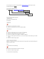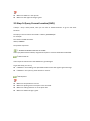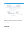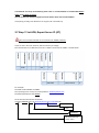
1
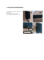
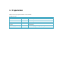
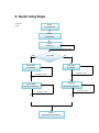
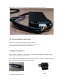
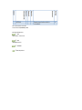
ESKY WIRELESS INC. [email protected] ES610 Getting Start Manual V1.2 2013 22-303,328 XINGHUSTREET,SUZHOU,CHINA Catalogue Version history .................................................................................................................................. 3 1. Structure Introduction .................................................................................................................. 4 2. Preparation.................................................................................................................................... 5 3. Quick Using Steps .......................................................................................................................... 6 3.1 Step 1: Insert SIM Card........................................................................................................ 7 3.2 Step 2: Install ES610 ............................................................................................................ 7 3.2.1 Connect Lines to ES610 ............................................................................................ 8 3.2.2 Connect ES610 to the Vehicle .................................................................................. 9 3.3 Step 3: Power On ................................................................................................................. 9 3.4 Step 4: Set APN, Report Server IP (SMS) ........................................................................... 10 3.5 Step 5: Query Current Location (SMS) .............................................................................. 12 3.6 Step 6: Login Car Online Platform ..................................................................................... 13 3.6.1 Visit Car Online Platform ........................................................................................ 13 3.6.2 Login Page .............................................................................................................. 13 3.6.3 Register an Account................................................................................................ 14 3.6.4 Default Account for User ........................................................................................ 15 3.6.5 Start Tracking.......................................................................................................... 15 3.6.5 Modes Switch Page ................................................................................................ 16 3.7 Step 7: Set APN, Report Server IP (AT) .............................................................................. 18 3.8 Step 8: Normal Function Test (AT) ..................................................................................... 19 4. Install and Operation ................................................................................................................... 21 4.1 Installation Method ........................................................................................................... 21 4.2 Installation Site .................................................................................................................. 21 4.3 Installation Notes .............................................................................................................. 22 5. Supplement ................................................................................................................................. 23 5.1 LED Indication.................................................................................................................... 23 5.2 Hardware Interface ........................................................................................................... 23 Version history Version Data Note V1.0 2013-10-8 First version V1.1 2013-10-11 Add chapter 3.6.4 Default Account for User V1.2 2013-11-21 Modify chapter 5.2 Hardware Interface 1. Structure Introduction ① ② ③ ④ ES610 works with power line and I/O line USB port Supply power port and I/O port Dimension: 83mm*43.2mm*17.7mm 1 ○ 2 ○ I/O port Supply power port 3 ○ 4 ○ 2. Preparation Make sure the equipments below are all available. Equipment Lists: Equipment Name Number Note ES610 1 Necessary GSM SIM Card 1 Necessary power Line 1 Necessary I/O Line 1 Necessary Power supply (12V- 36V) 1 Necessary (Cigarette Lighter/ OBD) Data line 1 Not Necessary (For AT command) 3. Quick Using Steps S: Success F: Fail Step 1 Insert SIM Card Step 2 Install ES610 Step 3 Power on F check, re-do SMS AT or SMS Step 4 (SMS) Set APN&IP AT Step 7 (AT) Set APN,IP F check, re-do F check, re-do S S Step 8 (AT) Normal Function Test Step 5 (SMS) Normal Function Test F check, re-do F check, re-do S S … … Step 6 Login Online Car Platform 3.1 Step 1: Insert SIM Card Open the terminal cover, and put the metal side of SIM card face down and then fasten the card slot cover. Note: SIM Hot-Plug is forbidden for this device. 1. Metal side faces 2. Fasten card slot 3.2 Step 2: Install ES610 The terminal is GPS positioning product, it is recommended that you follow the instructions to install. ① ② ③ I/O line Power supply line ④ 3.2.1 Connect Lines to ES610 First, connect power supply line to ES610. Plug the part ② of power supply line into ES610 power supply port (chapter 1 ③) Second, connect I/O line to ES610 Plug the part ④ of power supply line into ES610 power supply port (chapter 1 ③) 3.2.2 Connect ES610 to the Vehicle Power lines, it can connect with cigarette lighter or OBD I/O line, connects terminal with the I/O connector of wire harness. For the detailed description, please refer to chapter 4. 3.3 Step 3: Power On When finishing installation, as long as power supply line is connected with cigarette lighter or OBD, ES610 is powered on and starts work. Note: If ES610 is connected with cigarette lighter, then only the car is ignition on, cigarette lighter will has voltage. That means, ES610 can be powered on. (cigarette lighter) (OBD) Then, please check LEDs status. When ES610 is powered on, the two LEDs –Yellow and green LEDs will light for 10 seconds; then, only green LED will blink four times; after blinking, yellow and green LEDs will blink together. Wait for a while, yellow LED will light without blink. The meaning of each LED means, please refer to chapter 5.1, and hardware interface, please refer to chapter 5.2. If not, your situation is: 1) No LED lights Please check the way you power on or the voltage that power supplies. 2) Only green LED lights Please make sure that SIM card is inserted. Please make sure that SIM card is available. Please make sure that SIM card is not hot plug. Note: If you want to test all the commands via SMS, please refer to Step 3, Step 4 and Step 5. Or if set command by USB (AT), please refer to step 7, step 8. 3.4 Step 4: Set APN, Report Server IP (SMS) The command to re-set APN and server IP is “GPRS”. The format of “GPRS” is shown below. For example: The APN of China Mobile is CMNET. The reporting server is esky car online platform: www.eskylocate.com and the port is 1750. The default password is 000000 So the content of SMS should be: gprs,000000,cmnet,0, www.eskylocate.com:1750,120# Report server APN Password 1) The command possible responses: ①GPRS=Success! That means everything goes well. GO TO Step 5. ②GPRS=Fail! Make sure no parameters are missed. Make sure the password is the last six numbers of IMEI. ③No Response. Make sure GPRS spelling correct. No space in the beginning. Make sure ending character’#’. No space in the end. Make sure that SIM card has plugged, or plugged in right way. Make sure SIM supports SMS service. Try to use the SIM card send SMS by your mobile phone. Make sure GSM coverage is good. 2) After setting APN, IP and port Wait for 1 ~2 minutes, you will see that yellow LED is no longer blink. And if GPS has fixed, green LED does not blink, either. If not, ① Yellow LED never stops blinking. Make sure that the APN or IP and port are all right. Make sure GSM coverage is good. ② Green LED never stops blinking. Make sure ES610 is in the open air Make sure GPS signal coverage is good. 3.5 Step 5: Query Current Location (SMS) If Step1 ~ Step 4 have passed, Then you can refer to <ES610 Protocol> to go on test other functions. The Query Current Location command is “Where, [PASSWORD] #”. For example: The content of SMS should be: Where, 000000# The possible responses: ① WHERE=31.86384+120.92707+10.74468! If the reply SMS contains latitude, longitude and speed. It means that ES610 has GPS fixed. ② Where=0+0+0! If the response 0+0+0! means that ES610 can’t get GPS signal. To get GPS fixed, you can try: If ES610 is in the building, then put ES610 outdoor where GPS signal is good coverage. If ES610 is in the open air, please wait for a moment. ③No Response. Make sure the password is correct. Make sure spelling correct. No space in the command. Make sure ending character is ’#’. No space after. Make sure GSM coverage is good. 3.6 Step 6: Login Car Online Platform 3.6.1 Visit Car Online Platform Click: http://www.eskywireless.com.cn See Figure 1 Figure 1: Loading Page If you don’t see this page, please do: ①Check your Internet Connection. ②Check your operation system(No IOS). ③You don’t have install plug-in (sliverlight), Microsoft will give you the link of installation. If not, you have to install it by yourself: http://www.microsoft.com/getsilverlight/Get-Started/Install/Default.aspx 3.6.2 Login Page After finish loading, go into Log-In page. If the language of this log-in page is Chinese, please change the language. Just click the area where the red box notes in Figure 2. Figure 2: Chinese Log-In Page Figure 3 shows the English Log-In page. Now click “Not a member yet? Take a minute to sign up” to register an account. Figure 3: English Log-In Page 3.6.3 Register an Account Fill up all the items as shown in Figure 4. Without any error hints, click “Confirm”. Notes: ①Make sure IMEI is the exactly number you can see on the product label. Totally 15 numbers. And also it’s unique, so don’t register with using same IMEI. ②Table “Version”, please choose ES610. ③Make sure your E-mail address is correct. You can re-get your password via E-mail if you forgot the password. Figure 4: Register Pop-up After register successfully, return to Log-In page and enter the User Name and Password you just set. 3.6.4 Default Account for User eSky Wireless Inc. has an default account for user to experience the Car Online Platform. The default account: User name: esky Password: esky123456 You are welcome to use the above user name and password to register on our platform. 3.6.5 Start Tracking When you see the page like Figure 5, Congratulation! Now you can start tracking. Figure 5: Main tracking Page 3.6.5 Modes Switch Page If you have two or more ES610 devices, you can add the others in one account (Same UserID). Click the middle of 3*3 squared. As shown in Figure 6. Figure 6: Modes Switch Page Then click “Add” button, a new form will pop up shown in Figure 7. Enter new device’s information like register. Click “Confirm” to finish adding. Figure 7: Add Device Pop-up If commands are set by AT command, please refer to <serial Readme> to install ES610 device driver and set hyper terminal. You can contact our technical support to ask for device driver and <serial Readme>. If everything is ready, then follow me to enjoy the AT command trip. 3.7 Step 7: Set APN, Report Server IP (AT) Note: AT command is based on the command in <ES610 protocol>. If you are not in China or America, APN is necessary to change. The command to re-set APN and server IP is “GPRS”. The format of “GPRS” is shown below. For example: The APN of China Mobile is CMNET The reporting server is esky car online platform: www.eskyloacte.com The default password is the 000000 So the AT command content should be: cmd=gprs,000000,cmnet,0, www.eskyloacte.com:1750,120#<CR> Report server APN Password AT command mark cmd=” XXX “ Note: Do not forget the ENTER at the end of command. The possible response: ① OK GPRS=Success! It means APN, server IP have changed successfully. ② OK GPRS=Fail! Try again Please don’t set any command within 1 ~ 2 min after ES610 is powered on. Mark sure GPRS command spells correctly. ③ ERROR Make sure that AT command mark spells correctly. ④No response. Type “enter” again. Re-type GPRS command again without pause. 3.8 Step 8: Normal Function Test (AT) Since AT command is based on commands in <ES610 Protocol>, so you can choose whatever command you want to test by AT command. All you need to do is add AT command mark. Note: Function “where” cannot be set by AT command. For example: Command “interval”, format is shown below. AT command should be: cmd=interval,000000,120# Possible Response: ① OK INTE RVA L =Success! ② OK INTERVAL=Fail! ③ ERROR ④No Response. 4. Install and Operation 4.1 Installation Method Note: 1) The following installation order, please do not inverted. 2) During the installation process, please do not supply the terminal. The terminal installation is divided into hidden installation and open installation. When the terminal is using special vehicles, hidden installation is recommended. Otherwise, open installation is chosen. (To avoid thieves’ damage, the installation location should be hidden) 4.2 Installation Site The places that we suggest to install: The bottom of the front windshield decorative plates Around of front dashboard (epidermis as nonmetallic material) Below the decorative panels of rear windshield Inside the front bumper (should pay attention of water) Below the wipers plate (should pay attention of water) 4.3 Installation Notes ① Avoid put together with the emission source, for example, reversing radar, anti-theft devices and other on-board communications equipment. ② As for fixing the terminal, you can bound with ties or stick with wide sponge strength double-faced adhesive. ③ The terminal has GSM antenna and GPS antenna,so the installation should ensure that the ES610face up (that is GPS toward the sky). Besides, there is no on-metallic object that obscures above the terminal. ④ If your car’s windshield pasted with metal insulation layer or the heating layer, GPS receiving signal will be weakened, and it may cause GPS work abnormal. So please change the location you installed the terminal. 5. Supplement 5.1 LED Indication Yellow LED indicates GPRS status. Green LED indicates GPS status. Power ON Power OFF GPS Searching GPS Fix GREEN On 10-15sec Blink On YELLOW On 10-15sec See ** See ** **: When server is connected, the yellow light will on. When PDP is activated but no server connection, the yellow will blink every second. But if PDP cannot be activated, it shows off. 5.2 Hardware Interface ES610 has 3 INPUTs, 2 OUTPUTs. No. Definition Color Connection Note 1 V+ Red Positive electrode of car 12V/24V battery 2 V- Black Negative electrode of car 12V/24V battery 3 Input Orange 4 Input Yellow 5 I/O Brown 6 Output Green 7 Output Blue 8 USB Count from right to left: INPUT: orange wire is INPUT 0, yellow is INPUT 1, brown is INPUT 2; OUTPUT: green is OUTPUT 0, blue is OUTPUT 1 [email protected]