1
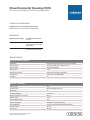
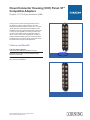
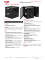
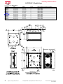
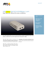
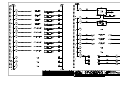
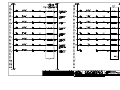
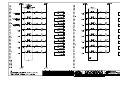
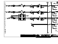
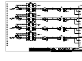
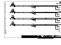
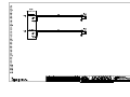
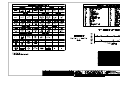
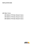
BOSSIER CITY RR NE WWTP EXPANSION & REHABILITATION BOSSIER CITY PROJECT 10-DQ-06, 10-BI-04 & 10-DQ-07 SUBMITTAL FOR Communication Cabling, Switches and Accessories (Security Camera System)-Records Storage Building D-16710-002-A 5/29/15 Submittal Number Date Tim Stewart Max Foote Construction Certification Statement: By this submittal, I hereby represent that I have determined and verified all field measurements, field construction criteria, materials, dimensions, catalog numbers and similar data and I have reviewed and approved this submittal and checked and coordinated each item with other applicable approved shop drawings and all contract requirements. Red River & NE WWTP Expansion & Rehab Project Bossier City, Louisiana City Project # 10-DQ-06 & 10-BI-04 MCG# 1002.111.10 Specification Section 16710 - Communication Cabling, Switches and Accessories Security Camera System Submittal Customer: Max Foote Construction Company, Inc. Mandeville, LA Subcontract No. 260-17000 Vendor: Revere Control Systems 2240 Rocky Ridge Road Birmingham, Alabama 35216 Submittal No. N0575-S-15r0-MIS Date: May 26, 2015 Table of Contents A. Notes and Exceptions B. Security Camera System Components Data Sheet B-1 Manufacturer Corning Catalog No. CCH-01U Description 19" Rack Mount Fiber Connector Housing B-2 Corning CCH-CP12-15T Multimode Connector Panel B-3 Eaton PW9130L700R-XL2U 700VA Rack Mount UPS B-4 Hoffman Black Box EWMW482425 37803-R2 19" Wall Mount Server Rack Horizontal Cable Management C. United Automation Record Storage Building Submittal D. Drawings N0575_RR-NETWORK N0575_RR-SPB-PLC-060 2 Red River WWTP Expansion and Rehabilitation Project NE WWTP Upgrade and Rehabilitation Project Bossier City, LA Records Storage Building Submittal Notes & Exceptions Specification Section 16721 – Fire Alarm System 1. Whenever possible, we have used the same manufacturer and model numbers used previously on projects for this site. 2. The existing Red River network drawings have been updated for this submittal. Items 62, 142-146 have been added to the BOM for this submittal. Page 1 of 1 Data Sheet No. B-1 CLOSET CONNECTOR HOUSING GENERAL 1 Specification Section 2 Component Code 3 Tag No. CLOSET CONNECTOR HOUSING 4 Description 5 Number of Ports 6 Fiber Count 7 Mounting MANUFACTURER & NO. 8 Manufacturer 9 Housing Model No. N0575-S-15r0-MIS : : : 16710 N/A N/A : : Closet Connector Housing (CCH), one rack unit, holds two CCH connector panels Up to 24 Up to 48 Rack 19-in, Rack 23-in, Cabinet-mount : : Corning CCH-01U : Closet Connector Housing (CCH) one rack unit, holds two CCH connector panels Closet connector housings (CCHs) provide interconnect or cross-connect capabilities between outside plant, riser or distribution cables and opto-electronics. Like other LANscape solutions hardware, the housings accept CCH connector panels. In addition, the housings accept CCH cassettes and CCH modules. From fiber and cable routing and strain relief, to port labeling and termination, these housings reduce the risk of error that can disrupt networks. The units are designed for rack mounting in 19-in (48 cm) racks or optional 23-in (58 cm) equipment racks (1.75-in EIA hole spacing). They are available in rack space options of 1U (two panels, cassettes or modules), 2U (four panels, cassettes or modules), 3U (six panels, cassettes or modules) and 4U (12 panels, cassettes or modules). The 1U, 2U and 3U options feature a slide-out tray and see-through, removable top covers. The CCH-04U features a clear door, removable front and rear enclosures and a platinum-colored interior for maximum visibility and access. Every CCH housing is shipped complete with strain relief brackets, routing clips and guides, and mounting brackets for proper installation. Documentation labels are provided and components can be added as needed to construct a fiber distribution frame for any application. All housings include a removable tinted polycarbonate front door. All size housings have field-installable lock kits available for both front and rear doors. All CCH housings can also be upgraded for pigtail splicing to full fiber capacity and easy, modular fiber management through the use of CCH Splice Cassettes (CCHCS), or for easy, modular fiber management when using field-installable connectors through the use of CCH Slack Cassettes (CCH-CF). Features and Benefits Interconnect and cross-connect capability Ideal for field connectorization Removable, translucent top covers (1U, 2U, 3U), removable rear cover (4U) Visibility and ease of access for installation, testing, and troubleshooting Internal and external strain-relief options Flexibility for installation and moves, adds, and changes (MACs) Accepts panels, modules, and cassettes Variety of field-termination options Product Specification CCH-01U_NAFTA_AEN Page 1 | Revision date 2015-03-06 Part Number: CCH-01U Closet Connector Housing (CCH) one rack unit, holds two CCH connector panels Features and Benefits Adaptable to use as a modular splice housing Splices are stored and protected in same footprint Standards Approvals and Listings Meets ANSI/TIA/EIA-568A and 606 RoHS Free of hazardous substances according to RoHS 2002/95/EG UL-Listed United States and Canadian safety standards Specifications General Specifications Application Enterprise Networks, Data Center, Carrier Networks Mounting Type Rack 19-in, Rack 23-in, Cabinet-mount Product Type Fiber Optic Hardware Environment Indoor Mounting Technology Flush mount, Protruding, Recessed Access Type Front and rear access slidable Lockable Yes Design - Hardware Housing Type CCH Housing Color Black, transparent top cover Height Unit 1U Locking Availability Front or rear Number of Panels per Housing Up to 2 Pigtail Length 2.25 m Panel or Module Type CCH Splice Tray Options CCH Splice Cassette (CCH-CS) Housing Material Powder-coated metal and Polycarbonate Tray Number of Ports Up to 24 Fiber Count Up to 48 Product Specification CCH-01U_NAFTA_AEN Page 2 | Revision date 2015-03-06 Closet Connector Housing (CCH) one rack unit, holds two CCH connector panels Design - Hardware Cable entry type External and Internal strain-relief bracket Number of splice cassettes Up to 2 Number of Adapters Up to 24 Number of pigtails Up to 48 Mechanical Characteristics Dimensions (HxWxD) 4.4 cm x 48.3 cm x 43 cm (1.75 in x 19 in x 17 in) Weight 3.9 kg Ordering Information Part Number CCH-01U Product Description Closet Connector Housing (CCH), one rack unit, holds two CCH connector panels Shipping Information Units per Delivery 1/1 Shipping Weight 4.5 kg (10 lb) Dimensions (HxWxD) 54.61 cm x 57.15 cm x 19.05 cm (21.5 in x 22.5 in x 7.5 in) Corning Optical Communications LLC • PO Box 489 • Hickory, NC 28603-0489 USA 800-743-2675 • FAX: 828-325-5060 • International: +1-828-901-5000 • www.corning.com/opcomm A complete listing of the trademarks of Corning Optical Communications is available at www.corning.com/opcomm/trademarks. All other trademarks are the properties of their respective owners. Corning Optical Communications is ISO 9001 certified. © 2015 Corning Optical Communications. All rights reserved. Product Specification CCH-01U_NAFTA_AEN Page 3 | Revision date 2015-03-06 Data Sheet No. B-2 CONNECTOR PANEL GENERAL 1 Specification Section 2 Component Code 3 Tag No. CONNECTOR PANEL 4 Description 5 Fiber Count 6 Number of Adapters per Panel MANUFACTURER & NO. 7 Manufacturer 8 Model No. N0575-S-15r0-MIS : : : 16710 N/A N/A : : : Closet Connector Housing (CCH) Panel, ST® Compatible adapters, Simplex, 12 F, 62.5 μm multimode (OM1) 12 12 : : Corning CCH-CP12-15T Closet Connector Housing (CCH) Panel, ST® Compatible Adapters Simplex, 12 F, 62.5 µm multimode (OM1) Corning closet connector housing panels (CCH-CP) are offered in a variety of fiber counts for use with LANscape® solutions hardware products for a “one-size -fits-all” approach. Used with factory-installed or fieldinstallable connectors, these panels provide interconnect or cross-connect capability in a housing at main crossconnects, intermediate cross-connects, telecommunication rooms or work areas. Available with a variety of industry-standard adapter types, the CCH-CP provides an efficient way to securely mate two connectors and offers multimode and single-mode applications. Features and Benefits Universal design approach One-size-fits-all LANscape® Solutions housings Broadest range of fiber count and adapter types Solutions for all needs Part Number: CCH-CP12-15T Colored icon labeling Easy connector identification Part Number: CCH-CP12-15T Product Specification CCH-CP12-15T_NAFTA_AEN Page 1 | Revision date 2015-01-22 Closet Connector Housing (CCH) Panel, ST® Compatible Adapters Simplex, 12 F, 62.5 µm multimode (OM1) Specifications General Specifications Application Enterprise Networks, Data Center LAN/SAN Product Type Panels & Modules Fiber Category 62.5 µm MM (OM1) Design - Hardware Fiber Count 12 Number of Adapters per Panel 12 Design Adapter Adapter Housing Color Beige Adapter Housing Material Metal Adapter Type ST® Compatible Insert Material Ceramic Chemical Characteristics RoHS Free of hazardous substances according to RoHS 2002/95/ EG Ordering Information Part Number CCH-CP12-15T Product Description Closet Connector Housing (CCH) Panel, ST® Compatible adapters, Simplex, 12 F, 62.5 µm multimode (OM1) Shipping Information Units per Delivery 1/1 Package Contents CCH Adapter Panel with installation guide Product Specification CCH-CP12-15T_NAFTA_AEN Page 2 | Revision date 2015-01-22 Closet Connector Housing (CCH) Panel, ST® Compatible Adapters Simplex, 12 F, 62.5 µm multimode (OM1) Notes Corning Optical Communications LLC • PO Box 489 • Hickory, NC 28603-0489 USA 800-743-2675 • FAX: 828-325-5060 • International: +1-828-901-5000 • www.corning.com/opcomm A complete listing of the trademarks of Corning Optical Communications is available at www.corning.com/opcomm/trademarks. All other trademarks are the properties of their respective owners. Corning Optical Communications is ISO 9001 certified. © 2015 Corning Optical Communications. All rights reserved. Product Specification CCH-CP12-15T_NAFTA_AEN Page 3 | Revision date 2015-01-22 Data Sheet No. B-3 RACKMOUNT UPS GENERAL 1 Specification Section 2 Component Code 3 Tag No. RACKMOUNT UPS 4 Type 5 Power rating (VA/watts) 6 Input 7 Output 8 Input cord length MANUFACTURER & NO. 9 Manufacturer 10 Model No. N0575-S-15r0-MIS : : : 16710 N/A N/A : : : : : 9130 Rackmount UPS 700/630 5-15P (6) 5-15R 6 ft. : : Eaton PW9130L700R-XL2U Product Brochure 700 VA - 3 kVA Eaton 9130 Rackmount UPS Online power quality and scalable battery runtimes for IT equipment Eaton 9130 Rackmount features and benefits Reliability: Online, double-conversion topology ensures that loads are powered with the highest level of protection available. Mission-critical applications benefit from zero transfer time to battery and an internal automatic bypass. In addition, premium power filtering is ideal for harsh environments where harmonics and other voltage disturbances may occur. Increased battery life: Eaton® offers ABM® technology that increases battery service life by 50 percent. ABM uses an advanced, three-stage charging technique and closely monitors battery health to provide advanced notice when batteries need replacement. More power: The 9130 allows you to connect more devices and leave room for expanding IT systems by providing up to 28 percent more wattage compared to traditional UPSs. Intelligent Power Software Suite By integrating the bundled Intelligent Power® Software Suite (IPSS), you can monitor and manage your network power devices. IPSS enables you to: •Seamlessly integrate with VMware’s vCenter™ Server™ virtualization management solution, as well as virtualization platforms such as Citrix® XenServer, Microsoft SCVMM™, Red Hat® and other Xen® open source platforms •Initiate live migration of virtual machines (VMs) to automatically and transparently migrate them during power disruptions to unaffected devices with systems such as VMware vMotion™ and Microsoft Live Migration •Gracefully shutdown computers, VMs and host servers during an extended power outage To learn more, please visit: Eaton.com/intelligentpower Manageability: •Load segmentation: Grouped outlets with remote control capability enable IT managers to cycle or shed loads through a webcard interface or based upon a preprogrammed schedule. •Eaton’s Intelligent Power Manager (IPM): IPM software provides network power management, ensuring data and system integrity. With IPM, you can have access to easy, versatile, remote monitoring and management of multiple devices. LCD interface: The bright, intuitive LCD user interface simplifies UPS monitoring and management. The user-friendly menu allows you to view all critical UPS information in a single view. Services and support Eaton provides 24x7 product support. From battery replacement to full UPS service plans, Eaton has one of the top service models in the industry. Front panel overview 1 4 2 5 3 Back panel overview 1 Rackmounting ears 2 Connect EBMs via front panel 3 Hot-swappable batteries 4 4-button menu with LCD interface and LED indicators 5 2U rack height 6 6 ft. (1.8 m) input cord with 5-20P 7 Load segment 1 with (3) 5-20R and (1) L5-20R 8 Load segment 2 with (3) 5-20R 9 Ground bonding screw 10 RPO (remote power off) port 11 Standard relay output contact 12 RS-232 port 13 USB port 14 Communications bay with optional Network-MS card* Model PW9130L2000R-XL2U (2 kVA, 120V output, 50/60 Hz) 7 6 10 12 9 8 13 11 14 *Virtualization-ready bundles with included Network Card-MS are available for select Eaton 9130 Rackmount UPS models, providing real time monitoring and control across UPSs within the network. See models listed below. 9130 Rackmount model selection guide Catalog number Power rating (VA/watts) North American models: 120V, 50/60 Hz PW9130L700R-XL2U 700/630 Input Output Dimensions (HxWxD, in.) (6) 5-15R 5-15P1 3.4 (2U) x 17.2 x 17.7 Weight (lb.) 35.3 PW9130L1000R-XL2U PW9130L1500R-XL2U PW9130L2000R-XL2U 1000/900 1500/1350 2000/1800 5-15P1 5-15P1 5-20P1 (6) 5-15R (6) 5-15R (6) 5-20R, (1) L5-20R 3.4 (2U) x 17.2 x 17.7 3.4 (2U) x 17.2 x 17.7 3.4 (2U) x 17.2 x 23.6 3.4 (2U) x 17.2 x 23.6 3.4 (2U) x 17.2 x 23.6 3.4 (2U) x 17.3 x 16.9 43.0 PW9130L2000R-XL2UN PW9130L3000R-XL2UN 2000/1800 3000/2700 5-20P1 L5-30P1 (6) 5-20R, (1) L5-20R (6) 5-20R, (1) L5-30R 3.4 (2U) x 17.3 x 22.6 3.4 (2U) x 17.3 x 22.6 63.9 65.0 3000/2700 3000/2700 L6-20P1 1) L6-30R, (1) L6-20R, (2) 6-20R 3.4 (2U) x 17.2 x 23.6 65.0 L6-20P1 (8) C13, (1) C19 3.4 (2U) x 17.2 x 23.6 65.0 PW9130L2500R-XL2U 2500/2250 (6) 5-20R, (1) L5-30R L5-30P1 PW9130L3000R-XL2U 3000/2700 (6) 5-20R, (1) L5-30R L5-30P1 North American models: 120V, 50/60 Hz Virtualization-ready bundles with Network Card-MS PW9130L1500R-XL2UN 1500/1350 (6) 5-15R 5-15P1 Global models: 208V, 50/60 Hz PW9130G3000R-XL2U PW9130G3000R-XL2UEU 35.3 43.0 63.9 65.0 65.0 International models: 230V, 50/60 Hz PW9130i1000R-XL2U 1000/900 C142 (6) C13 3.4 (2U) x 17.2 x 17.7 35.3 PW9130i1500R-XL2U PW9130i2000R-XL2U PW9130i3000R-XL2U C142 C142 C203 (6) C13 (8) C13, (1) C19 (8) C13, (1) C19 3.4 (2U) x 17.2 x 17.7 3.4 (2U) x 17.2 x 23.6 3.4 (2U) x 17.2 x 23.6 43.0 63.9 65.0 1500/1350 2000/1800 3000/2700 Extended battery modules PW9130N1000R-EBM2U Works with 700/1000 VA models, where available PW9130N1500R-EBM2U Works with 1500 VA models PW9130N3000R-EBM2U Works with 2000-3000 VA models, where available Rackmount bypass accessories Catalog number Style number Input plug Breaker Max kW EHBPL1500R-PDU1U EHBPL2000R-PDU1U EHBPL3000R-PDU1U EHBPI3000R-PDU1UIEC 58115 58120 58130 68433 1. Input cord length is 6 ft. 2. C14, w/ detachable L6-20P. 3. C20, w/ detachable L6-20P. Additional notes: TAA-compliant models: Eaton now offers TAA-compliant models for the 9130. Please visit Eaton.com/taaups for model specific information. 5-15P 5-20P L5-30P C20 None None (2) 20A (1) 20A 1.44 1.92 2.88 3000 3.4 (2U) x 17.2 x 17.7 48.7 3.4 (2U) x 17.2 x 17.7 3.4 (2U) x 17.2 x 23.6 62.0 90.6 Function Cord (ft.) Orientation Receptacles Dimensions (HxWxD, in.) BA BA BA BA 8 8 3.3 2U 2U 2U 2U (6) 5-15R (6) 5-15R (5) 5-20R (1) C19, (6) C13 2.1 x 17.3 x 3.8 2.1 x 17.3 x 3.8 2.1 x 17.3 x 3.8 2.1 x 17.3 x 4.8 Other available options – Environmental Monitoring Probe – PowerPass Distribution Modules – 1U HotSwap Maintenance Bypass Visit Eaton.com/9130RM for details. Eaton 1000 Eaton Boulevard Cleveland, OH 44122 Eaton.com © 2014 Eaton All Rights Reserved Printed in USA 9130RFXA September 2014 For complete battery runtime information and to interact with the 9130 Rackmount UPS, please visit: Eaton.com/9130RM Eaton, ABM and Intelligent Power are registered trademarks of Eaton. All other trademarks are property of their respective owners. Data Sheet No. B-4 SERVER RACK GENERAL 1 Specification Section 2 Component Code 3 Tag No. SERVER RACK 4 Type 5 Rack Units 6 Material : : : 16710 N/A N/A : : : ACCESSPLUS® II Double-Hinge, Type 1 26 Pretreated steel coated with RAL 9005 black light-textured, low-gloss polyester powder paint MANUFACTURER & NO. 7 Manufacturer 8 Model No. 9 Cable Management No. : : : Hoffman EWMW482425 Black Box 37803-R2 N0575-S-15r0-MIS Networking: Wall-Mount Cabinets ACCESSPLUS® II Double-Hinge Spec-00534 EPH (763) (763) 422-2588 422-2661 FX Networking Wall-Mount Cabinets ACCESSPLUS® II Double-Hinge ACCESSPLUS® II Double-Hinge, Type 1 Industry Standards Specifications Front Door (window or solid steel) •• Composite frame (injection molded top and bottom with extruded composite sides) EIA 310-D •• 140-degree opening door NEMA/EEMAC Type 1 •• Field-reversible (left or right) hinge EIC 60529 IP20 •• Quarter-turn key lock, two keys included Per BICSI TDMM Tenth edition, Chapter 7, •• Window door is scratch-resistant 1/4-in. tinted safety glass Telecommunication Enclosures (TE) •• Solid door has 16 gauge steel insert with matching black finish Center Section Application •• Welded 14 gauge steel ACCESSPLUS® II Cabinets provide security, equipment access, cooling •• Solid top of center sections provides protection against falling and support for network and other 19-in. rack-mount equipment. The debris cabinet has three components: front door, center section and wall •• Ventilated sides (to which fans can be added) section. •• Self-latching closure connects center section to wall section •• Self-alignment ramp supports center section to wall section Features •• Heavy duty center-to-rear section hinge with quick-release self•• Double-hinged for easy equipment access; center section provides retained hinge pin eases wall installation 19-in. rack mounting per EIA universal spacing and is accessed Rack-Mounting Angles through the front door or swing the center section away from the •• 12 gauge, plated steel wall section for rear access •• EIA universal spaced 19-in. rack-mounting holes •• Round corners; no sharp edges •• RU marked from bottom to top •• Front door has either a solid steel or hardened, tinted safety-glass •• Tapped 10-32 holes, 20 mounting screws included window door for superior scratch resistance Rear Wall Section •• Center section easily removed from rear section; tool-less one•• Welded 14 gauge steel person installation possible •• Radius corners; no sharp edges •• Self-grounding, plated steel rack angles fully adjustable within •• Available with knockouts or gland plates center section •• Raised pads for accessory mounting •• Wall section provides cable entry and cable management with •• Cable tie-down points for cable management knockouts or gland plates •• Keyhole mounting holes allow wall section to be mounted over •• Gland plate model provides easy retrofit and fast installation and fasteners and eases installation allows for pre-terminated cables or pre-wired patch panels; no •• Three cable-entry grommets need to re-terminate and test Finish •• Self-locking center-to-wall section latches in two locations •• Front access to all latches (no exposed side latches); cabinet can be Pretreated steel coated with RAL 9005 black light-textured, low-gloss installed tightly in corners polyester powder paint. Other finishes available—contact Hoffman •• Vented sides provide cross flow ventilation to improve heat Customer Service. dissipation Bulletin: DWDH1 •• Vertical cable manager included in 28-in.-wide models •• A full line of accessories is available UL 508A; Type 1; File No. E61997 cUL Listed per CSA C22.2 No. 182.4; File No. E230874 Subject to change without notice PH (763) 422-2661 • FX (763) 422-2588 • hoffmanonline.com © 2010 Pentair Technical Products Spec-00534 E 1 Networking: Wall-Mount Cabinets ACCESSPLUS® II Double-Hinge Standard Product Window Door AxBxC in. Catalog Number EWMW242418 23.60 x 23.62 x 18.20 EWMW362418 36.02 x 23.62 x 18.20 EWMW482418 48.03 x 23.62 x 18.20 EWMW602418 60.04 x 23.62 x 18.20 EWMW722418 72.05 x 23.62 x 18.20 EWMW242425 23.62 x 23.62 x 25.09 EWMW362425 36.02 x 23.62 x 25.09 EWMW482425 48.03 x 23.62 x 25.09 EWMW602425 60.04 x 23.62 x 25.09 EWMW722425 72.05 x 23.62 x 25.09 EWMW242430 23.62 x 23.62 x 30.01 EWMW362430 36.02 x 23.62 x 30.01 EWMW482430 48.03 x 23.62 x 30.01 B dimension does not include wall-to-center section hinge. 2 Subject to change without notice AxBxC mm 600 x 600 x 462 915 x 600 x 462 1220 x 600 x 462 1525 x 600 x 462 1830 x 600 x 462 600 x 600 x 637 915 x 600 x 637 1220 x 600 x 637 1525 x 600 x 637 1830 x 600 x 637 600 x 600 x 762 915 x 600 x 762 1220 x 600 x 762 Rack Units 12 19 26 32 39 12 19 26 32 39 12 19 26 Additional Rack Angles (S=Square Hole) (T=Tapped Hole) EWMR24T or EWMR24S EWMR36T or EWMR36S EWMR48T or EWMR48S EWMR60T or EWMR60S EWMR72T or EWMR72S EWMR24T or EWMR24S EWMR36T or EWMR36S EWMR48T or EWMR48S EWMR60T or EWMR60S EWMR72T or EWMR72S EWMR24T or EWMR24S EWMR36T or EWMR36S EWMR48T or EWMR48S PH (763) 422-2661 • FX (763) 422-2588 • hoffmanonline.com © 2010 Pentair Technical Products Spec-00534 E Security Camera Systems For Record Storage Building Red River WWTP Bossier City, LA Revere Control Systems 2240 Rocky Ridge Road Birmingham, AL 35216 Engineer Manchac Consulting Group, Inc. Quail Run Drive, Suite A Baton Rouge, LA. 70808 Waste Water System Improvements Record Storage Building Red River WWTP Switch REC-NSW-080 (qty: 1) Switch has 16 POE+ ports Redundant power supplies SFP Gigabit module (qty: 2) Cameras Axis Q-6042 (qty: 6) includes midspan Product information MACH104-16TX-PoEP -R Industrial Ethernet:Workgroup Switches:Gigabit/10 Gigabit Ethernet PoE Workgroup Switches, 22-24 Ports:MACH104-16TX-PoEP -R http://e-catalog.hirschmann.com/link/57078-24455-49848-85613-158780/en/conf/uistate Name MACH104-16TX-PoEP -R 20 Port Gigabit Ethernet Industrial Workgroup Switch (16 x GE TX PoEPlus Ports, 4 x GE SFP combo Ports), managed, Software Layer 2 Professional, Store-andForward-Switching, IPv6 Ready Delivery informations Availability available Product description Description 20 Port Gigabit Ethernet Industrial Workgroup Switch (16 x GE TX PoEPlus Ports, 4 x GE SFP combo Ports), managed, Software Layer 2 Professional, Store-andForward-Switching, IPv6 Ready Port type and quantity 20 Ports geamt; 16 x (10/100/1000 BASE-TX, RJ45) PoEPlus und 4 x Gigabit Combo Ports (10/100/1000 BASE-TX, RJ45 oder 100/1000 BASE-FX, SFP) Type MACH104-16TX-PoEP -R Order No. 942 026-001 More Interfaces Power supply/signaling contact 1 x terminal block 2-pins, contact manually or automatically (max. 1 A, 24 V DC or 24 V AC) V.24 interface 1 x RJ11 socket, serial interface for device configuration USB interface 1 x USB to connect the AutoConfiguration Adapter ACA21-USB Network size - length of cable Twisted pair (TP) 0 m ... 100 m Multimode fiber (MM) 50/125 µm see SFP LWL-Module M-FAST SFP-MM/LC and SFP LWL-Module M-SFP-SX/LC Multimode fiber (MM) 62.5/125 µm see SFP LWL-Module M-FAST SFP-MM/LC and SFP LWL-Module M-SFP-SX/LC Single mode fiber (SM) 9/125 µm see SFP LWL-Module M-FAST SFP-SM/LC und SFP LWL-Module M-SFP-LX/LC Single mode fiber (LH) 9/125 µm (long haul see SFP LWL-Module M-FAST SFP-SM+/LC transceiver) 10G-Multimode fiber (MM) 50/125 µm n/a 10G-Single mode fiber (SM) 9/125 µm n/a Network size - cascadibility Line - / star topology any Ring structure (HIPER-Ring) quantity switches 50 (reconfiguration time < 0.3 sec.) Power requirements Operating voltage 100-240 VAC, 50-60 Hz (redundant) Heat dissipation 119 Btu (IT) h Heat dissipation at max. PoE power 235 Btu (IT) h Power consumption 35 W Software Management serial Interface, web interface, SNMP V1/V2, HiVision file transfer SW HTTP/TFTP, LLDP-MED Diagnostics LEDs, log-file, syslog, relay contact, RMON, port mirroring 1:1 and n:1, egress/ingress traffic configurable, topology discovery 802.1AB, cable tester (TX), address conflict detection, network error detection, SFP diagnostic [temperature, optical input and output power (μW and dBm)], Trap for configuration saving and changing, duplex mismatch detection, disable learning, Port Monitor Configuration Comand line interface (CLI), TELNET, BootP, DHCP, DHCP option 82, HIDiscovery, easy device exchange with auto-configuration adapter ACA21-USB (automatic software and/or configuration upload), automatic script load from ACA21, integrated DHCP server per port, DHCP relay, automatic invalid configuration undo, Offline Configuration, SFP Whitelist, ARC automatic ring configuration (MRP), automatic port shutdown (link flapping), configuration signature (water marking), overload detection Security ACL/QoS, ACL Layer 4 fragment support, Port Security (IP und MAC) with multiple addresses (MAC 50 per port), SNMP V3, SSH, Authentication (IEEE802.1x), 802.1x Multi Cliant Authentication, Guest VLAN and Unauthenticated VLAN, Port based Radius VLAN assignment, MAC notification Redundancy functions HIPER-Ring, MRP, MSTP, RSTP - IEEE802.1D-2004, MRP and RSTP gleichzeitig, Link Aggregation Filter QoS 8 classes, priorisation (IEEE 802.1D/p), VLAN (IEEE 802.1Q), Voice VLAN, shared VLAN learning, Q-in-Q double VLAN tagging, multicast IGMP v1/v2/v3, (snooping/querier), multicast detection unknown multicast, broadcast-, unicast-, multicast limiter, fast aging, GMRP IEEE 802.1D, Jumbo Frame Support, Hirschmann Automation and Control GmbH www.beldensolutions.com 08-08-2014 Page 1 of 2 Industrial Ethernet:Workgroup Switches:Gigabit/10 Gigabit Ethernet PoE Workgroup Switches, 22-24 Ports:MACH104-16TX-PoEP -R http://e-catalog.hirschmann.com/link/57078-24455-49848-85613-158780/en/conf/uistate Industrial Profiles, EtherNet/IP und PROFINET (2.2 PDEV, GSDML Stand-alone generator, automatic device exchange) profiles included, configuration and diagnostic via automation, software tools like e.g. STEP7, oder Control Logix IEC61850 protocol (MMS Server, Switch Model) Time synchronisation PTP IEEE 1588 v1/v2 Boundary and Transparent Clock hardware time stamping with accuracies of 30ns, SNTP server, realtime clock with energy buffer Flow control Flow Control 802.3x, Port Priority 802.1D/p, Priority (TOS/DIFFSERV), Prio (MAC/IP), Prio Mapping (TOS Layer2), Traffic Shaping (Unicast, Multicast, Broadcast), Ingress / Egress Ambient conditions Operating temperature 0 ºC ... 50 ºC Storage/transport temperature -20 ºC ... 85 ºC Relative humidity (non-condensing) 10 % ... 95 % MTBF n/a Mechanical construction Dimensions (W x H x D) 448 mm x 44 mm x 345 mm Mounting 19" control cabinet Weight 4500 g Protection class IP20 Mechanical stability IEC 60068-2-27 shock 15 g, 11 ms duration, 18 shocks IEC 60068-2-6 vibration 3.5 mm, 5–8.4 Hz, 10 cycles, 1 octave/min; 1 g, 8.4–150 Hz, 10 cycles, 1 octave/min EMC interference immunity EN 61000-4-2 electrostatic discharge (ESD) 4 kV contact discharge, 8 kV air discharge EN 61000-4-3 electromagnetic field 10 V/m (80-3000 MHz) EN 61000-4-4 fast transients (burst) 2 kV power line, 4 kV data line EN 61000-4-5 surge voltage power line: 2 kV (line/earth), 1 kV (line/line), 4 kV data line EN 61000-4-6 conducted immunity 10 V (150 kHz-80 MHz) EMC emitted immunity FCC CFR47 Part 15 FCC 47 CFR Part 15 Class A EN 55022 EN 55022 Class A Approvals Safety of industrial control equipment cUL 508 Safety of information technology equipment cUL 60950-1 Scope of delivery and accessories Scope of delivery Device, terminal block for signal contact, 2 brackets with fasteningscrews (pre-assembled), housing feet - stick-on, non-heating appliance cable - Euro model, CD-ROM with user manual, installation user manual Accessories to order separately Fast Ethernet SFP modules, Gigabit Ethernet SFP modules, autoConfiguration Adapter ACA21-USB, terminal cable, Industrial Hivision Network Management software For more information please contact: Hirschmann Automation and Control GmbH Stuttgarter Strasse 45-51 72654 Neckartenzlingen Germany Phone: +49 7127/14-1809 E-Mail: [email protected] The information published in the websites has been compiled as carefully as possible. It is subject to alteration without notice in technical as well as in price-related/commercial respect. The complete information and data were available on user documentation. Mandatory information can only be obtained by a concrete query. Hirschmann Automation and Control GmbH www.beldensolutions.com 08-08-2014 Page 2 of 2 The MACH4000 SFP Fiber Optic Fast-, Gigabit- and 10Gigabit- Ethernet Transceivers SFP fiber optic Fast-Ethernet transceiver Description SFP fiber optic Fast-Ethernet transceiver Type M-FAST SFP-LH/LC M-FAST SFP-SM+/LC M-FAST SFP-SM/LC M-FAST SFP-MM/LC 943 868-001 943 867-001 943 866-001 943 865-001 Order number Network size – length of cable Multimode fiber (MM) 50/125 μm (62.5/125 μm) Single mode fiber (SM) 9/125 μm 5km (4 km at 62.5/125 μm) 40 – 104 km 25 – 65 km 25 km Technical data Port type and quantity Diagnostics Operating voltage Power consumption Operating temperature 1x100BASE-FX with LC-Connector Optical input- and output power, transceiver temperature (diagnostic not for M-FAST SFP-MM/LC) Power supply via media module 1W 0° C up to + 60° C SFP fiber optic Gigabit-Ethernet transceiver Description SFP fiber optic Gigabit-Ethernet transceiver Type Order number M-SFP-LH+/LC M-SFP-LH/LC M-SFP-LX/LC M-SFP-SX/LC 943 049-001 943 042-001 943 015-001 943 014-001 Network size – length of cable Multimode fiber (MM) 50/125 μm (62.5/125 μm) Single mode fiber (SM) 9/125 μm 550m (275m at 62.5/125 μm) 60 –120 km 24 – 72 km 20 km Technical data Port type and quantity Diagnostics Operating voltage Power consumption Operating temperature 1x1000BASE-SX with LC-Connector Optical input- and output power, transceiver temperature Power supply via media module 1W 0° C up to + 60° C XFP fiber optic 10Gigabit-Ethernet transceiver Description XFP fiber optic 10Gigabit-Ethernet transceiver Type M-XFP-ZR/LC M-XFP-ER/LC M-XFP-LR/LC M-XFP-SR/LC Order number 943 921-001 943 920-001 943 919-001 943 917-001 Network size – length of cable Multimode fiber (MM) 50/125 μm (62.5/125 μm) Single mode fiber (SM) 9/125 μm 300m (26m at 62.5/125 μm) 40 –80 km 10 – 40 km 10 km Technical data Port type and quantity Diagnostics Operating voltage Power consumption Operating temperature 1x10GBASE-SX with LC-Connector Optical input- and output power, transceiver temperature Power supply via media module 3W 0° C up to + 60° C Hirschmann Technical Support 1.717.217.2261 8 ©Copyright 2012, Belden Inc. www.belden.com/hirschmann MACH4000 | 092012 DATASHEET AXIS Q6042 PTZ Dome Network Camera Indoor, high-speed PTZ dome with 36x zoom > 36x optical zoom and Extended D1 > IP52-rated protection against dust and dripping water > Shock detection > Enhanced intelligent video > PoE+ AXIS Q6042 is an advanced indoor PTZ dome, offering higher resolution than normal D1, 36x optical zoom, and fast and precise pan/tilt performance for wide area coverage and great detail when zooming in. It is ideal for airports, train stations, arenas, shopping malls and warehouses. Supporting round-the-clock pan/tilt/zoom operation, the robust AXIS Q6042 can be automatically directed to 256 preset positions using guard tour. With endless 360° pan and high zoom, the camera can monitor an extremely wide area and provide detailed surveillance. The camera’s adjustable day/night functionality ensures high image quality even in low light conditions. AXIS Q6042 has IP52-rated protection against dust and dripping water, and support for Power over Ethernet Plus (IEEE 802.3at) using the supplied High PoE midspan. The PTZ dome also has shock detection, which mechanically detects and triggers an alarm if the camera has been hit. In vibrating conditions, the camera’s electronic image stabilization reduces the effects of camera vibrations on the view to deliver clearer video. AXIS Q6042’s built-in video analytics include Active Gatekeeper, which enables the camera to automatically move to a preset position when motion is detected in a pre-defined area, and track the detected object. The camera also has substantial capacity for third-party intelligent video applications. With an optional multi-connector cable, AXIS Q6042 supports two-way audio, I/O ports for external devices and AC/DC power. The camera has a built-in memory card slot for local storage of recordings. Technical Specifications - AXIS Q6042 PTZ Dome Network Camera Models AXIS Q6042 50 Hz, AXIS Q6042 60 Hz Camera Image sensor 1/4” ExView HAD progressive scan CCD Lens f=3.3 – 119 mm, F1.4 – 4.2, autofocus Horizontal angle of view: 57.2° - 1.7° Day and night Automatically removable infrared-cut filter Minimum illumination Color: 0.5 lux at 30 IRE F1.4 B/W: 0.008 lux at 30 IRE F1.4 Shutter time 1/30000 s to 1.5 s (50 Hz),1/30000 s to 0.5 s (60 Hz) Pan/Tilt/Zoom Pan: 360° endless, 0.05° – 450°/s Tilt: 180°, 0.05° – 450°/s 36x optical zoom and 12x digital zoom, total 432x zoom E-flip, 256 presets, Tour recording, Guard tour, Control queue, On-screen directional indicator Video Video compression H.264 Main and Baseline Profiles (MPEG-4 Part 10/AVC) Motion JPEG Resolutions Extended D1 736x576 to 176x144 (50 Hz) Extended D1 752x480 to 176x120 (60 Hz) Frame rate H.264: Up to 25/30 fps (50/60 Hz) in all resolutions Motion JPEG: Up to 25/30 fps (50/60 Hz) in all resolutions Video streaming Multiple, individually configurable streams in H.264 and Motion JPEG Controllable frame rate and bandwidth; VBR/CBR H.264 Image settings Wide dynamic range (WDR), Electronic image stabilization, Manual shutter time, Compression, Color, Brightness, Sharpness, White balance, Exposure control, Exposure zones, Backlight compensation, Fine tuning of behavior at low light, Rotation, Text and image overlay, 32 individual 3D privacy masks, Image freeze on PTZ Audio Audio streaming Two-way Audio compression AAC-LC 8/16 kHz, G.711 PCM 8 kHz, G.726 ADPCM 8 kHz Configurable bit rate Audio input/output Requires multi-connector cable (sold separately) for external microphone or line input, and line output Network Security Password protection, IP address filtering, HTTPSa encryption, IEEE 802.1Xa network access control, Digest authentication, User access log Supported protocols IPv4/v6, HTTP, HTTPSa, SSL/TLSa, QoS Layer 3 DiffServ, FTP, CIFS/SMB, SMTP, Bonjour, UPnPTM, SNMPv1/v2c/v3 (MIB-II), DNS, DynDNS, NTP, RTSP, RTP, TCP, UDP, IGMP, RTCP, ICMP, DHCP, ARP, SOCKS System integration Application Open API for software integration, including VAPIX® Programming and AXIS Camera Application Platform; specifications at Interface www.axis.com AXIS Video Hosting System (AVHS) with One-Click Camera Connection ONVIF Profile S; specifications at www.onvif.org Intelligent video Video motion detection, Autotracking, Active Gatekeeper, AXIS Camera Application Platform enabling installation of additional applications Event triggers Video motion detection, Audio detection, Shock detection, Fan, External input, Manual trigger, Autotracking, PTZ moving, PTZ preset, Edge storage events, AXIS Camera Application Platform Event actions File upload: FTP, HTTP, network share and email Notification: email, HTTP and TCP External output, PTZ preset, Guard tour, Play audio clip, Video and audio recording to edge storage, Autotracking, Day/night mode, Pre- and post-alarm video buffering Built-in installation aids Pixel counter General Casing IP52-rated metal casing (aluminum), acrylic (PMMA) clear dome Memory 512 MB RAM, 128 MB Flash Power Power over Ethernet Plus (PoE+) IEEE 802.3at, max. 30 W AXIS T8123 High PoE midspan 1-port: 100-240 V AC, max. 37 W 24–34 V DC, max. 19 W; 20–24 V AC, max. 27 VA Connectors RJ45 for 10BASE-T/100BASE-TX PoE Multi-connector (cable sold separately) for AC/DC power, 4 configurable alarm inputs/outputs, mic in, line mono input, line mono output to active speaker Edge storage SD/SDHC/SDXC slot supporting memory card up to 64 GB (card not included); support for recording to dedicated network-attached storage (NAS) Operating conditions 0 °C to 50 °C (32 °F to 122 °F) Humidity 10–85% RH (non-condensing) Storage conditions -40 °C to 65 °C (-40 °F to 149 °F) Approvals EN 55022 Class A, EN 61000-3-2, EN 61000-3-3, EN 61000-6-1, EN 61000-6-2, EN 55024, FCC Part 15 Subpart B Class A, ICES-003 Class A, VCCI Class A, C-tick AS/NZS CISPR 22 Class A, KCC KN22 Class A, KN24, IEC/EN/UL 60950-1, IEC/EN 60529 IP52, IEC 60721-4-3 Class 3K3, 3M3, IEC 60068-2 Midspan: EN 60950-1, GS, UL, cUL, CE, VCCI, CB, KCC, UL-AR Weight Camera: 2.6 kg (5.7 lb.); with drop-ceiling mount: 3.2 kg (7.1 lb.) Included accessories AXIS T8123 High PoE Midspan 1-port, Mounting kit for hard and drop ceilings, Smoked dome cover, Installation Guide, Installation and Management Software CD, Windows decoder 1-user license Video management software AXIS Camera Companion (included), AXIS Camera Station and video management software from Axis’ Application Development Partners (not included) Warranty Axis 3-year warranty and AXIS Extended Warranty option, see www.axis.com/warranty a. This product includes software developed by the OpenSSL Project for use in the OpenSSL Toolkit. (www.openssl.org), and cryptographic software written by Eric Young ([email protected]). More information is available at www.axis.com Dimensions Optional accessories 1. Hard-ceiling mount 1. Axis mounting accessories 2. Drop-ceiling mount 2. AXIS T90A Illuminators 3. Multi-connector cable for AC/DC power, I/Os and audio 4. AXIS T8310 Video Surveillance Control Board ©2013 Axis Communications AB. AXIS COMMUNICATIONS, AXIS, ETRAX, ARTPEC and VAPIX are registered trademarks or trademark applications of Axis AB in various jurisdictions. All other company names and products are trademarks or registered trademarks of their respective companies. We reserve the right to introduce modifications without notice. 54353/EN/M1.6/112013 www.axis.com DATASHEET AXIS T8123 High PoE 30 W Midspan 1-port High Power over Ethernet for indoor installations. > Reduced installation costs > IEEE 802.3at and IEEE 802.3af compliance >Plug-and-play installation > Support for Axis PTZ dome network cameras Axis T8123 midspan offer an easy, fast and cost-effective solution for powering network video products, without the need to install power outlets and electrical cabling. AXIS T8123 midspan connects are connected to the mains power, transforming the power and inject it into the network cable enabling Axis network video products to receive data and power over the same Ethernet cable. AXIS T8123 is an High PoE product, which makes it easier to install network video products in areas where power cabling and outlets are unavailable, thereby reducing installation costs. This midspan is used to power all network devices that are IEEE 802.3af or at compliant, meaning that it can be used with all Axis network video products with built-in PoE support. Technical Specifications – AXIS T8123 High PoE 30 W Midspan 1-port Midspan Model Function Data rate AXIS T8123 High PoE 30 W Midspan 1-port Data and power are fed to a network video product through an Ethernet cable; use together with a High PoE splitter for a network video product without built-in PoE support 10/100/1000 Mbps Data & Power Connectors Shielded RJ45, EIA 568A and 568B Network cables Shielded category 5 (or higher) Wiring Data provided over pairs 1/2 and 3/6 for 10/100 Ethernet, over all four pairs for Gigabit Ethernet Power over spare pairs 4/5 (+) and 7/8 (-) 55 V DC (max. 30 W) Output power Input power Installation and management AC Input Voltage: 100 to 240 V AC (max. 37 W) AC Frequency: 50 - 60 Hz Plug-and-play installation; automatically detects PoE and High PoE-enabled devices and supplies inline power Local LED management display General Display and indicators Compliance Port interfaces are located on the front panel System indicator: AC power Channel indicator: Power For more information, see www.axis.com/techsup RoHS, WEEE, CE, IEEE 802.3af, IEEE 802.3at Mounting Wall or shelf mounting Approvals Operative conditions Storage FCC Part 15, Class B with FTP cabling, EN 55022 Class B, EN 55024, VCCI, CB, UL/cUL per EN 60950-1, GS Mark per EN 60950-1, KCC, UL-AR -10 °C to 55 °C (14 °F to 131 °F) Humidity max. 95% RH (non-condensing) -20 ˚C to 70 ˚C (-4 ˚F to 158 ˚F) Dimension 51 x 88 x 166 mm (2 x 3.5 x 6.5 in) Environment Indoor Weight 350 g (0.7 lb) More information is available at www.axis.com and on products’ Installation Guide ©2013 Axis Communications AB. AXIS COMMUNICATIONS, AXIS, ETRAX, ARTPEC and VAPIX are registered trademarks or trademark applications of Axis AB in various jurisdictions. All other company names and products are trademarks or registered trademarks of their respective companies. We reserve the right to introduce modifications without notice. 54251/EN/R1/1310 www.axis.com AXIS Q-6042 (Typical) T-REC-CAM082-1 T-REC-CAM081-1 Records Storage Building REC-CAM-085 CAT 6 By others CAT 6 By others T-REC-CAM083-1 CAT 6 By others CAT 6 By others Records Storage Building REC-CAM-084 Records Storage Building REC-CAM-086 CAT 6 By others 315 Wallace Dean Road West Monroe, LA 71291 P.O. Box 607 West Monroe, LA 71294 Phone: 318-397-0208 Fax: 318-397-0140 CAT 6 By others T-REC-CAM086-1 Records Storage Building REC-CAM-083 T-REC-CAM085-1 Records Storage Building REC-CAM-082 T-REC-CAM084-1 ENTRANCE GATE ADM-CAM-081 Building Automated Systems Fire Safety Access Controls Nurse Call CCTV Security Data & Phone Systems Intercom Energy Solutions Sound Systems CAT6 Patch Cords by others Axis Midspan T8123 (mounted by data Rack) REC-NSW-080 Rack by others WORK STATION Fiber Optic Jumpers by others Architect Engineer Mech. Contractor Elec. Contractor REC-FOP-080 SERVER Catalyst 2948G-GE-TX CONSOLE 1 2 3 4 5 6 7 8 9 10 11 12 13 14 15 16 17 18 19 20 21 22 23 24 25 26 27 28 29 30 31 32 33 34 35 36 37 38 39 40 41 42 43 44 45 46 47 48 10/100 MGT STATUS PSI 49 50 RPSU 51 52 by others ADM-OWS-080 (Existing) ADM-SVR—080 (Existing) Administration Building Records Storage Network to tie into existing Red River Network (By Others) Record Storage Building REC-UPS-080 REC-NER-080 4/30/15 JU