1
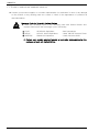
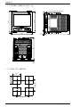
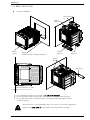
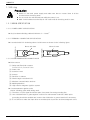
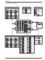
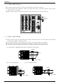
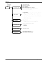
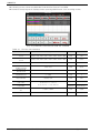
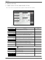
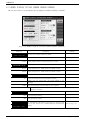
SDR100 -- S
SE
ER
RIIE
ES
S
SDR102, SDR104, SDR106, SDR112
User Manual
Digital Recorder
SAMWONTECH
※ This Manual applies to SDR102, SDR104, SDR106, SDR112.
The model stated the manual content is SDR112.
Contents
1. Instruction (Warning) on Safety
1.1 Product Check........................................................................................................................................
3
1.2 Dimensions and Installation............................................................................................................
5
1.3 Wiring
.........................................................................................................................................................
8
2. Operation and Setup
2.1 Function and Name of Display Part...........................................................................................
11
...................................................................................................................................
12
2.3 Initial Operation Flow..........................................................................................................................
14
....................................................................................................................
15
................................................................................................................................
15
3.1 Main Menu...............................................................................................................................................
17
2.2 Menu Flow Chart
2.4 Setup Button Operation
2.5 Parameter Setting
3. Set Operation Status
3.2 Graph Record Screen
.........................................................................................................................
4. Function Setup.................................................................................................................................................
18
20
5. Graph Option
5.1 Graph Display Option (Graph Record Screen)....................................................................
23
5.2 Graph Display Option (Graph Search Screen)....................................................................
24
6. Set Reserve Operation....................................................................................................................................
26
7. Display Set..........................................................................................................................................................
28
8. Canned Message Set....................................................................................................................................
30
9. Error History Display.......................................................................................................................................
31
10. Search Graph
10.1 Graph View..........................................................................................................................................
33
.........................................................................................................................................
34
10.2 Data Search
1st Edition of SDR100 Series IM : Feb. 01. 2010
1/2
SAMWONTECH
11. System Parameter Set Screen
11.1 Sensor Input Set Screen.................................................................................................................
11.2 Sensor Input Set Screen-2
..........................................................................................................
36
38
12. Alarm Signal
12.1 Alarm Signal Set Screen-1...........................................................................................................
12.2 Alarm Signal Set Screen-2
...........................................................................................................
12.3 Alarm Signal Operation...................................................................................................................
41
42
44
13 Pictures View
13.1 Pictures View Set Screen..............................................................................................................
13.2 Customer Pictures Set
....................................................................................................
45
46
14. DI Configuration..............................................................................................................................................
48
15. Communication Set.......................................................................................................................................
49
16. Initial Display Set............................................................................................................................
51
* Engineering Unit
1st Edition of SDR100 Series IM : Feb. 01. 2010
SAMWONTECH
1. SAFETY PRECAUTIONS
Thank you for purchasing SDR112, Digital Recorder.
This User Manual describes installing and operating procedures of the SDR112.
Safety Symbol Mark
(A) Symbolizes ‘Caution’ and ‘Warning’. The information with this symbol is especially
important for preventing from user injury and protecting the product and system.
(1) Product : This symbol indicates an imminently hazardous situation which if
not avoided, will result in serious injury or system damage.
(2) Operation Manual : This symbol indicates potential hazard that may cause
personal injury by electrical shock.
(B) Symbolizes ‘Protective Earth (PE) Terminal.’
This symbol indicates that the terminal must be connected to the Ground prior
to operating.
(C) Symbolizes ‘Supplementary Explanation.’
The information with this symbol describes additional explanation for features.
(D) Symbolizes ‘Reference.’
☞
This symbol indicates further information and page to refer.
Precautionary Remarks on this User Manual
(A) This manual should be passed on the End- User and kept at a suitable place for easy
review in time.
(B) Read and understand this Operation Manual carefully before using the product.
(C) This Operation Manual describes functions and features of the product in detail, and
SAMWONTECH can not guarantee against over applications would suit a customer’s
particular purpose which is not described in this manual.
(D) Unauthorized duplication and modification of this Operation Manual are strongly
prohibited.
(E) The contents of this manual may be modified without prior notice.
(F) If any errors or omissions in this manual should come to the attention of the user, feel
free to contact our sales representatives or our sales office.
1st Edition of SDR100 Series IM : Feb. 01. 2010
Page 1 / 53
SAMWONTECH
Precautions for Safety and Unauthorized Modification
(A) For protecting and ensuring the safety of this product and relevant system, all of the
safety instructions and precautions should be well recognized and strictly observed
by all users.
(B) SAMWONTECH does not guarantee against damage resulting from unauthorized
alteration, misuse, or abuse.
(C) When using additional safety circuit or part such as Noise Filter to protect this
product and relevant system, it is strongly required to install that to outside of this
product. Additional installation and modification inside of this product are prohibited.
(D) Do not try to disassemble, repair, or modify the product. It may become the cause of
a trouble such as malfunction, electric shock, fire.
(E) Contact our sales dept. for part replacement or consumables.
(F) Keep the product away from water inflowing. This may become a critical cause of
trouble.
(G) External shock on the product may lead to damage and malfunction.
음Limitation of Liability 음
(A) SAMWONTECH does not guarantee or accept responsibility for this product other
than the clauses stated in our warranty policy.
(B) SAMWONTECH assumes no liability to any party for any loss or damage, direct or
indirect, caused by the use or any unpredictable defect of the product.
음Warranty Policy 음
(A) Warranty term of this TEMI2500 is one year after delivery to the first purchaser for
being free of defects in materials and faulty workmanship under the condition that
the product has been applied according to this manual.
(B) The repairing cost will be charged for defective product out of warranty period. This
charge will be the actual cost estimated by SAMWONTECH.
(C) Repairing cost may be charged even if within warranty period for following cases.
(1) Damage due to user fault (Ex.: Product initialization by password loss)
(2) Damage due to natural disaster (Ex.: fire, flood)
(3) Damage due to additional removal and re-installation after the first one.
(4) Damage due to unauthorized disassemble, modification and alternation.
(5) Damage due to unexpected power failure caused unstable power supply.
(6) Others
(D) If any A/S is required, feel free to contact our sales office or a representative.
1st Edition of SDR100 Series IM : Feb. 01. 2010
Page 2 / 53
SAMWONTECH
1.1 PACKAGE CHECKPOINT
▶ Please check any damage to the product by inspecting the appearance of the delivered product
first. In addition, check the following items.
1.1.1 VERIFY THE MODEL SUFFIX CODE
▶ Check to see if specifications of the delivered product are the same as those of your order.
Verify model suffix code printed on labels at the right of packing box and the left of product
case
Model
Spec Code
Additional
Additional
Additional
Additional
Code 1
Code 2
Code 3
Code 4
Description
02
2 Channel
04
4 Channel
06
6 Channel
12
12 Channel
- N
Not used
- C2
RS-232C(Option)
- C4
RS-485(Option
- CE
Ethernet(Option)
N
SDR1□□
Not used
Relay Output 6 point
A1
(Option)
Relay Output 12 point
A2
(Option)
N
Not used
Remote (DI) Input 2 point
R1
(Option)
/M1
Arithmetic Function
/P1
Portable Type
1.1.2 HOW TO CHECK COMPONENTS IN THE PACKAGE
▶ Check to see if the following components are included.
SDR100_SERIES Main
Body
SD CARD
1st Edition of SDR100 Series IM : Feb. 01. 2010
Fixing Mount(L:2, R:2)
Manual
Page 3 / 53
SAMWONTECH
1.1.3 HOW TO HANDLE ANY DAMAGED PRODUCT
▶ Contact your product supplier or our sales representative for assistance in case of any damage
to the product or any missing parts as a result of check in the appearance of products as
described above.
Exchange Cycle for Parts with Limited Lifetime
▶ Check the exchange cycle of the following parts with limited lifetime and
replace them before their exchange cycle if necessary.
■
■
■
FUSE
RELAY
BATTERY
2A/250VAC Equivalent
ALD105, ALD5V Equivalent
CR2030 3V Equivalent
: Semi-permanent
: Under ON/OFF 300,000 Times
: Under 200,000 HOUR
☞ Contact your product supplier (agents) or our sales representative for the
exchange of parts with limited lifetime.
1st Edition of SDR100 Series IM : Feb. 01. 2010
Page 4 / 53
SAMWONTECH
1.2 DIMENSION AND INSTALLATION
1.2.1 ENVIRONMENTS FOR INSTALLATION
Environmental Precautions
(A) Be sure to power on and operate the product after installation on a panel to prevent
electric shock)
(B) Do not install the product at following places or environment.
■ Anybody may touch the terminal inadvertently
■ Mechanical vibration or shock
■ Corrosive gas or combustible gas
■ Temperature fluctuation
■ Too hot (> 50℃) or Cold (< 10℃)
■ Direct rays of light or heat radiation
■ Magnetic or electromagnetic noise
■ High humidity ( > 85%)
■ Flammable materials
■ Wind blow, Dust with salt
■ Ultra violet rays
(C) Do not use sharp material or press with excessive force when operating touchscreen.
(D) Please be careful in handling the product because the product’s external case is
composed of plastics which is weak to organic solvent (chemical). (Especially be
careful not to contact front panel with organic solvent.)
☞ Avoid installing the product in such places with combustible objects upon fire
although the case of this product is made from fire retardant materials with
ABS/PC.
Precautions before Installation
(A) Keep the product away from possible noise sources.
(B) Keep the product in 10∼50℃, 20∼90%RH (non condensing) and be careful not to
expose heat generating sources.
(C) Do not mount with a position that the front panel facing downward.
(D) Storage should be within -25∼70℃, 5∼95%RH (non condensing). At a cold
condition below 10℃, sufficient warming-up should be preceded by the control
operation.
(E) Turn off the main power of the product before wiring to prevent electric shock
(F) The power rating of the product is 100~240VAC, 50/60Hz, 15VAmax. Be sure to use
suitable power source to prevent overheating or electric shock.
(G) Do not work with wet hands to prevent electric shock.
(H) The precautions and procedures in the manual should be kept to avoid a hazard such
as fire, injury, and electric shock.
(I) Installation and Operation procedures should be done just as in this manual.
(J) Make the grounding connection according to the way in manual. Do not use a tap
water piping, a gas pipe, a telephone line, a lightning rod to avoid possible accidents
such as explosion or inflammation.
(K) Do not power on the product before the wiring procedure is not completed..
(L) Do not block or wrap the heat vent holes in the case of the product. That may cause
a failure.
(M) Over-voltage protection category II and Pollution Degree II are rated for the product.
1st Edition of SDR100 Series IM : Feb. 01. 2010
Page 5 / 53
SAMWONTECH
1.2.2 EXTERNAL DIMENSION (UNIT: mm)
144
158
2~7mm (Panel Thickness)
6.5
181
6.5
181
144
1.2.3 PANEL CUT DIMENSION
+2
0
180(MIN)
137 +20
137
180(MIN)
1st Edition of SDR100 Series IM : Feb. 01. 2010
Page 6 / 53
SAMWONTECH
1.2.4 MOUNT INSTALLATION
▶
Product Installation
Fixing Mount
R
Fixing
Mount L
Insertion
Direction
Displa
y Area
Panel
(Refer to Plane Cutting Dimension)
Fixing
Mount L
Fixing
Mount R
Fixing
Mount
+ Type Driver
Panel Thickness: 2~7mm
① Cut the panel according to the table at [1.2.3 Panel Cutouts]
② Put the DISPLAY UNIT into the panel from the back shown as above picture.
③ Tie-up the main body of DISPLAY UNIT on the panel with Fixing Mount shown
as above picture.
Case distortion or mount damage may occur when it is too much tightened.
Tighten with under 0.5N·m torque when mounting product to panel.
.
1st Edition of SDR100 Series IM : Feb. 01. 2010
Page 7 / 53
SAMWONTECH
1.3 Wiring
Precaution
▶ Switch off the main power supply and make sure that no current flows in all the
circuits before the wiring work.
▶ Do not touch the real terminal part while the power is on.
▶ Main circuit breaker must be kept in OFF state until all the wiring work is done.
1.3.1 WIRING SPECIFICATION
1.3.1.1 POWER CABLE SPECIFICATION
▶ Vinyl insulated shielding cable KSC3304 0.9 ~ 2.0mm2
1.3.1.2 TERMINAL CONNECTOR SPECIFICATION
▶ A terminal with PVC insulating sleeve for M3 screw as shown in the following figure.
1.3.1.3 COUNTERMEASURES AGAINST NOISE
Above 3.0mm
Under 5.8mm
Under Φ5.8mm
Above Φ3.0mm
▶ Noise source
(1) Relay and Electrical contacts
Solenoid Coil, Solenoid Valve
(2) Power Line
(3) Inductive Load
(4) Inverter
(5) Rectifier of a Motor
(6) Phase-angle controlled SCR
(7) Wireless communication devices
(8) Welding Machine
(9) High-tension magneto-Ignition system
▶ Countermeasures against noise
Notice following guide while wiring work.
(1) The wires of input signal should be apart from power line and grounding line.
(2) Use a shielded wire to guard against a noise from electrostatic induction. Multi-point
grounding should be avoided and connect the shield wire to ground terminal if necessary.
(3) It is effective to make the input wires as a twisted pair to prevent an electromagnetic noise.
1st Edition of SDR100 Series IM : Feb. 01. 2010
Page 8 / 53
SAMWONTECH
1.3.2 TERMINAL ASSIGNMENT
Sensor Input (CH7~ CH12)
CH7
19
A
CH9
25
20
b+
26
b+ 32
b+
21
B-
27
B- 33
B-
A
CH11
31
Remote(DI/ Option)
13 REMOTE1
A
CH8
22
A
CH10
28
23
b+
29
b+ 35
b+
24
B-
30
B- 36
B-
A
CH12
34
Power
L
14 REMOTE2
15
COM
N
~ 100~
240VAC
F/G
A
Ethernet (Option)
Sensor Input (CH1 ~ CH6)
Relay Output (Option)
CH1
1
A
CH3
7
2
b+
8
b+ 14
b+
3
B-
9
B- 15
B-
A
CH5
13
RLY7
1
RLY1
17 COM
2
COM
18
RLY8
3
RLY2
19 COM
4
COM
A
20
RLY9
5
RLY3
21 COM
6
COM
22
7
RLY4
23 COM
8
COM
24
9
RLY5
16
A
CH2
4
A
CH4
10
5
b+
11
b+ 17
b+
6
B-
12
B- 18
B-
A
CH6
16
RLY10
RLY11
25 COM
10 COM
26 RLY12
11
27 COM
12 COM
1st Edition of SDR100 Series IM : Feb. 01. 2010
RS485/232C(Option)
RTX+
TXD
RTXRXD
SG
RLY6
Page 9 / 53
SAMWONTECH
1.3.3 POWER SOURCE WIRING
▶ For power source wiring, use a vinyl-insulated wire (KSC 3304 or better).
▶ Use more than 2mm2 thickness cable, and higher than Type 3 Grounding (under 100Ω ground
resistance) for grounding.
▶ Make 1 point ground from ground terminal, and avoid wiring over ground terminal.
L
N
~ 100~
240VAC
F/G
1.3.4 ANALOG INPUT WIRING
▶ SDR112 main power and external power supply should be turned off during remote input wiring
since there is danger of electric shock.
▶ Use shielded cable for input wiring. Also, make 1-point grounding for the shield.
▶ Signal line of Analog Input wiring should have gap from power line or ground line.
▶ Use cable with low resistance and have no resistance difference between 3 wires.
(A) RESISTANCE TEMPERATURE DETECTOR INPUT (RTD INPUT)
SHIELD
RTD
Type 3 GND
(B) DC VOLTAGE INPUT
(C) DC CURRENT INPUT
SHIELD
SHIELD
+
V
Type 3 GND
1st Edition of SDR100 Series IM : Feb. 01. 2010
+
R
DCmA
Type 3 GND
Page 10 / 53
SAMWONTECH
2. OPERATION AND SETUP
▶ This product is Digital Recorder designed with Touch Screen interactive display for convenience
of the customer.
2.1 FUNCTION AND NAME OF DISPLAY PART
④
⑤
③
⑥
②
①
①
②
③
④
⑤
⑥
Cover (Power Switch, SD CARD Port, Mini USB Ports appears when open the cover.)
SDR112 Power Switch
SD CARD Port
Lamp (Turning on yellow lamp when supplying power.)
Screed Display Area
MINI USB(For A/S: Not available for user)
1st Edition of SDR100 Series IM : Feb. 01. 2010
Page 11 / 53
SAMWONTECH
2.2 MENU FLOW CHART
Power On
Horizontal/Vertical Graph, Digital Graph, Bar Graph : Switching by Key
Initial
Screen
Operating
Screen
Function to select Message
Function to change Sampling Time by Key
Graph Recording Stop/Run
Function to Capture Graph Screen
Main Key
MAIN
MENU
Display for INTERNAL MEMORY, SD CARD, Alarm Status
Graph
Search
1. View stored graph (Time/Range, Reduction/Expansion)
and Snap Picture
Set Operation
1.
2.
3.
4.
5.
6.
7.
8.
Set Storage Interval (Interval 1 / Interval 2)
Set Main Button Restriction (Set Password)
Set Storage Media (INTERNAL MEMORY/ SD CARD)
Set Power Recovery Option
Set use of Pen
Set High/Low Limit of Graph Scale
Select Pen Thickness/Color
Set PV Display
Graph Display Option
1.
2.
3.
4.
5.
6.
Set
Set
Set
Set
Set
Set
Graph Display
Set Message
Graph (Trend) Direction (Horizontal/Vertical)
Graph (Trend) Background Color
Scale Display
Pen Type
Reference Line 1
Reference Line 2
1. Set Graph Display Message
Display Error History
1. Display Remote/Alarm History
2. Display Event/System Message History
Set Reserve Operation
1. Set Current Time
2. Set Reserve Operation
Set Screen Display
1.
2.
3.
4.
5.
6.
7.
Display Error History
1. Display Remote/Alarm History
2. Display Event/System Message History
1st Edition of SDR100 Series IM : Feb. 01. 2010
Set Buzzer Sound
Set Lamp Brightness
Set Automatic Channel Switch
Set Energy Save Function for Channel
Display INTERNAL MEMORY Information
Display SD CARD Information
Display Digital Graph
Page 12 / 53
SAMWONTECH
Password
Input
Setup
Screen
Set Sensor Input
Alarm Signal
DI Function &
Operation
1.
2.
3.
4.
5.
6.
7.
Set
Set
Set
Set
Set
Set
Set
Sensor Type
Unit of Display
Tag Name
Thermocouple (T/C) Display
Sensor Range
PV Direction on Sensor Open Circuit
Measurement Method
1. 4 ea/Channel
- Type: PV High Limit, PV Low Limit, Within PV
Range, Out of PV Range, Above PV Increase
Rate, Under PV Decrease Rate, Within Interchannel Deviation, Over Inter-channel Deviation,
Sensor Open Circuit
- Time Delay Occurred
1. Set DI Name
2. Events for DI
- Storage Interval, Error and Storage Time
Communication
Environment Set
1. Set by Communication Option
- RS-485
- RS-232C
- Ethernet
Set User Screen
1. Set User Screen
Set System
Initialization
1. Set Display Language
2. Set Initial Screen Information
3. All Parameter Up/Download
1st Edition of SDR100 Series IM : Feb. 01. 2010
Page 13 / 53
SAMWONTECH
2.3 INITIAL OPERATION FLOW
▶ Supplying the power after completing installation correctly, loading screen will appear for
loading time then Initial Logo screen will be displayed. The screen will automatically progress to
the Recording Stop screen
☞ It takes around 18 seconds for loading.
▶ MENU BAR is displayed when pressing
button at the top right hand corner on Graph
Recording Stop Screen, and screen switches to MAIN MENU when pressing
(MAIN) button.
▶ Initial screen can be changed as user want. Refer to the [System Initialize Set] for how to
change initial Screen
<LOADING SCREEN>
<SYSTEM PARAMETER SET
<INITIAL SCREEN>
<PASSWORD ENTER SCREEN>
<RECORDING STOP SCREEN>
<MAIN MENU SCREEN>
SCREEN>
< SYSTEM PARAMETER SET
SCREEN WITHOUT DI
OPTION>
< SYSTEM PARAMETER SET
SCREEN WITHOUT
COMMUNICATION OPTION>
1st Edition of SDR100 Series IM : Feb. 01. 2010
< SYSTEM PARAMETER SET
SCREEN WITHOUT DI/
COMMUNICATION OPTION>
Page 14 / 53
SAMWONTECH
2.4 SETTING BUTTONS
▶ [Table2-1] describes BASIC SETTING BUTTONS.
Table 2-1. BASIC SETTING BUTTONS
Button Type
Description
Button to set general numerical and alphabetical value.
Button to set on multiple options.
Button to select on of several modes or options.
(ON / OFF / INACTIVE)
Button to set whether or not to use each parameter.
(ON / OFF / INACTIVE)
Screen move button to move to the next / previous Screen in the same group.
Page move button to move to the next / previous Page in the same screen.
2.5 PARAMETER SETTING
▶ When you pressing the
button, the following Input Keypad appears and the required
data value can be set by using this Input Keypad.
▶ If the setting value is out of the available range, ‘LIMIT ERROR’ message will appear with a
‘BEEP’ sound and input will be rejected.
① Numeric keypad to input numerical values
② Alpha- numeric keypad to input PASSWORD
③ LIMIT ERROR message when out of available rage
1st Edition of SDR100 Series IM : Feb. 01. 2010
Page 15 / 53
SAMWONTECH
④ Alpha- numeric keypad to input PATTERN NME or MESSAGE
1st Edition of SDR100 Series IM : Feb. 01. 2010
Page 16 / 53
SAMWONTECH
3. OPERATION SETTING
3.1 MAIN MENU SCREEN
⑨
③
①
④
②
⑦
⑤
⑧
⑥
⑩
[Fig. 3-1] MAIN MENU
Number
Indication
Description
①
GRAPH RECORD
Move to STOP/RECORD SCREEN
②
GRAPH SEARCH
Move to DATA (GRAPH) SEARCH SCREEN stored to INTERNAL MEMORY/SD
CARD.
③
FUNCTION SET
Move to FUNCTION AND OPERATION TYPE SET SCREEN
④
GRAPH OPTION
Move to GRAPH DISPLAY OPTION (GRAPH RECORD & SEARCH) SCREEN.
⑤
CANNED MESSAGE
⑥
RESERVE SET
Move to CURRENT TIME & RESERVE OPERATION SET (START/END) SCREEN.
⑦
DISPLAY SET
Move to DISPLAY SET and INTERNAL MEMORY/SD CARD CAPACITY DISPLAY
SCREEN
⑧
ERROR HISTORY
⑨, ⑩
HIDDEN KEY
Move to MESSAGE SETUP SCREEN.
Move to ERROR AND EVENT HISTORY related screen.
Move to SYSTEM PARAMETER SET SCREEN
1st Edition of SDR100 Series IM : Feb. 01. 2010
Page 17 / 53
SAMWONTECH
3.2 GRAPH RECORD SCREEN
3.2.1 GRAPH RECORD STOP SCREEN
▶ Press “GRAPH RECORD” on [3.1 MAIN MENU] screen to enter into this screen, and “GRAPH
RECORD STOP SCREEN” will be displayed
▶ All buttons do not operate during screen capture.
[Fig. 3-2] GRAPH RECORD STOP SCREEN-1
Symbol
[Fig. 3-3] GRAPH RECORD STOP SCREEN -2
Description
Symbol
Description
Screen capture button that user wants to
capture.
Icon indication during captured screen
storage.
Icon to indicate
Capacity.
Icon to indicate that there is no space in
INTERNAL MEMORY.
INTERNAL
MEMORY
Icon to indicate that SD CARD is not
inserted or not recognized.
Icon to indicate SD CARD capacity
Menu bar on/off button at the top of graph.
Button to switch from 1 ~ 6 CH. SCREEN to 7 ~ 12 CH. SCREEN. (Displayed only at SDR112)
This icon blinks during recording.
The light rotates clockwise when ALARM is generated.
Display current time and date. Touching this area will switch to BACKLIGHT SAVE MODE, and yellow
lamp is on at the top of product. (Red : Record stop state, Yellow : Recording state)
Symbol
Description
Pressing MAIN button will switch to [Fig. 3-1 MAIN MENU].
Switch to BAR GRAPH SCREEN from TREND SCREEN.
Switch to DIGITAL SCREEN from TREND SCREEN.
Can enter message or display setup message when pressing MESSAGE button.
Pressing STORAGE INTERVAL button will switch INTERVAL 1 Æ INTERVAL 2 or INTERVAL 2Æ
INTERVAL 1.
Pressing RECORD button will start storage according to storage media setup of [OPERATION SET].
1st Edition of SDR100 Series IM : Feb. 01. 2010
Page 18 / 53
SAMWONTECH
3.2.2 GRAPH RECORD OPERATION SCREEN
▶ Operation screen is consisted of 4 screens.
▶ Each channel is indicated with specific color.
▶ Can set the name of each channel.
3.2.2.1 TREND RECORD SCREEN
▶ Background color of TREND (Vertical/Horizontal) RECORD SCREEN can be either black or white.
▶ Error and event history message are displayed only at TREND (VERTICAL/HORIZONTAL)
RECORD STOP and RECORDING SCREEN.
▶ When ALARM is generated, measured value of that channel becomes red color, and the light
rotates to clockwise direction.
③
①
④
⑤
②
[Fig. 3-4] TREND (VERTICAL/HORIZONTAL) SCREEN
No.
Description
①
Display current PV to scale bar, and can set PV DISPLAY as TAG or BAR at [Operation Set].
②
Display TIME (DATE/TIME) that corresponds to current time frame.
③
[1MIN/DIV] indicates the period (minute) per scale (division) at time frame of screen.
④
Indicates CH No., unit, measured value for each channel.
⑤
Pressing
(Check Box) of each channel toggles the display of the corresponding Channel.
▶ This is DIGITAL and BAR RECORD SCREEN.
[Fig. 3-5] DIGITAL DISPLAY SCREEN
1st Edition of SDR100 Series IM : Feb. 01. 2010
[Fig. 3-6] BAR GRAPH SCREEN
Page 19 / 53
SAMWONTECH
4. FUNCTION SET
▶ This screen is to set additional functions of the product.
[Fig. 4-1] RECORDING METHOD SET SCREEN-1 [Fig.4-2]
Symbol
RECORDING
METHOD
SET
Description
Switch from current screen to next screen.
Set all parameters as KEY LOCK.
☞ It is able to release the state of Screen Switch and Key Lock.
Move to corresponding channel during PARAMETER SETUP.
Switch to CH. 7 ~ 12 group.
Change current selected channel
parameter.
Instruction
Apply the parameter to all channels.
Description
Remark
Set RECORDING CYCLE.
FIRST
RECORDING CYCLE corresponding to INTERVAL 1 at recording
screen.
SECOND
RECORDING CYCLE corresponding to INTERVAL 2 at recording
screen.
☞
Changed by RECORDING CYCLE key from recording screen or REMOTE2 operation.
Set RECORD MEDIA according to RECORD button.
MEM
SD
BOTH
Store record data to INTERNAL MEMORY.
Store record data to SD CARD.
Store record data to INTERNAL MEMORY and SD CARD.
Set recovery action from power outage.
STOP
HOT
Stop storage action.
Store to new file.
1st Edition of SDR100 Series IM : Feb. 01. 2010
Page 20 / 53
SAMWONTECH
☞
Store record to history and display message to graph when recovering from power
outage.
When set to MAIN BUTTON RESTRICTION, keypad to enter
password appears when pressing MAIN button at FUNCTION
SET SCREEN.
Refer to [Fig. 4-5]
Set whether to use PEN (PV GRAPH DISPLAY) at recording
screen.
☞
It is not displayed and stored to recording screen when PEN USING is set to
UNUSE.
Set high/low limit value of scale bar in recording screen.
Set PEN (PV GRAPH DISPLAY) thickness.
☞
Set current line thickness to 1 pixel or 3 pixels.
Set PV DISPLAY indicated to scale bar of recording screen.
TAG
Display scale bar as TAG shape.
Refer to [Fig. 4-4]
BAR
Display scale bar as BAR shape.
Refer to [Fig. 4-3]
▶ Followings are the PV DISPLAY TYPE SCREEN.
[Fig. 4-3] PV DISPLAY TYPE SET SCREEN (BAR) [Fig. 4-4] PV DISPLAY TYPE SET SCREEN (TAG)
1st Edition of SDR100 Series IM : Feb. 01. 2010
Page 21 / 53
SAMWONTECH
▶ Following screen shows the MAIN BUTTON RESTRICTION SET SCREEN.
▶ Password setup keypad is displayed when pressing MAIN button from recording screen.
[Fig. 4-5] MAIN BUTTON RESTRICTION SET SCREEN
.Table 4-1. Function Set Parameter
Parameter
Set Range
Unit
Default Value
FIRST SAMPLING
CYCLE
0.5Sec, 1Sec, 2Sec, 5Sec, 10Sec, 20Sec, 30Sec, 1Min
ABS
1sec
SECOND SAMPLING
CYCLE
0.5Sec, 1Sec, 2Sec, 5Sec, 10Sec, 20Sec, 30Sec, 1Min
ABS
0.5sec
STORAGE MEDIA
MEM, SD, BOTH
ABS
MEM
RECOVERY FROM
POWER OUTAGE
STOP, HOT
ABS
STOP
MAIN BUTTON
RESTRICTION
UNUSE, USE
ABS
UNUSE
MAIN BUTTON
PASSWORD SET
0 ~ 9999
ABS
0
CH#n PEN SET
UNUSE, USE
ABS
USE
CH#n.EU
CH#n.EU(100%)
CH#n.EU
CH#n.EU(0%)
CH#n GRAPH SCREEN
HIGH LIMIT
CH#n GRAPH SCREEN
LOW LIMIT
CH#n.EU(-5.0 ~ 105.0%)
CH#n.DISPLAY < CH#n.DISPLAY
CH#n PEN THICKNESS
SET
1 PIXEL, 3 PIXEL
ABS
1 PIXEL
CH#n PV SCREEN SET
TAG, BAR
ABS
TAG
.#n : CH1 ~ 12
1st Edition of SDR100 Series IM : Feb. 01. 2010
Page 22 / 53
SAMWONTECH
5. GRAPH OPTION
5.1 GRAPH DISPLAY OPTION (GRAPH RECORD OPTION)
▶ It is the screen to set parameter that is applied to GRAPH RECORD SCREEN.
[Fig. 5-1] GRAPH DISPLAY OPTION SCREEN (GRAPH RECORD)
Instruction
Description
Remark
Set TREND DIRECTION of record screen.
Y-AXIS
Display TREND RECORD SCREEN DIRECTION to Y-AXIS.
Refer to [Fig. 4-3]
X-AXIS
Display TREND RECORD SCREEN DIRECTION to X-AXIS.
Refer to [Fig. 4-4]
Set background color of TREND RECORD SCREEN.
BLACK
Display background of TREND RECORD SCREEN as black.
Refer to [Fig. 4-3]
WHITE
Display background of TREND RECORD SCREEN as white.
Refer to [Fig. 4-4]
Set whether to use SCALE DISPLAY.
ALL
Display SCALE BAR and SCALE RANGE by channel.
ONE
Display SCALE BAR and SCALE RANGE of CHANNEL 1.
NONE
Both SCALE BAR and SCALE RANGE are not displayed.
☞
When set to “ONE”, all operates as “TAG” regardless of each channel “PV
DISPLAY” set value.
Set PV GRAPH DISPLAY TYPE.
DOT
DOT type data recording.
LINE
LINE type data recording.
Set REFERENCE LINE display and position of left end, right
end, top end, bottom end of GRAPH(VERTICAL/HORIZONTAL)
GRAPH.
1st Edition of SDR100 Series IM : Feb. 01. 2010
Refer to [Fig. 5-3]
Page 23 / 53
SAMWONTECH
5.2 GRAPH DISPLAY OPTION (GRAPH SEARCH SCREEN)
▶ It is the screen to set parameter that is applied to GRAPH SEARCH SCREEN.
[Fig. 5-2] GRAPH DISPLAY OPTION SCREEN (GRAPH SEARCH)
Instruction
Description
Remark
Set direction of TREND SEARCH SCREEN.
Y-AXIS
Display TREND SEARCH SCREEN direction to Y-AXIS.
X-AXIS
Display TREND SEARCH SCREEN direction to X-AXIS.
Set background color of TREND SEARCH SCREEN.
BLACK
Display background of TREND SEARCH SCREEN as black.
WHITE
Display background of TREND SEARCH SCREEN as white.
Set whether to use SCALE BAR DISPLAY.
ALL
ONE
NONE
Display SCALE BAR and SCALE RANGE by channel.
Display only one SCALE BAR, and SCALE RANGE is not
displayed.
Both SCALE BAR and SCALE RANGE are not displayed.
☞
When set to “ONE”, all operates as “TAG” regardless of each channel “PV
DISPLAY” set value.
Set PV GRAPH DISPLAY TYPE.
DOT
DOT type data recording.
LINE
LINE type data recording.
Set REFERENCE LINE DISPLAY and position of left end, right
end, top end, bottom end of TREND (VERTICAL/HORIZONTAL)
GRAPH.
1st Edition of SDR100 Series IM : Feb. 01. 2010
Refer to [Fig. 5-3]
Page 24 / 53
SAMWONTECH
▶ Followings are the RECORD AND SEARCH SCREEN with REFERENCE LINE 1, 2.
[Fig. 5-3] RECORD AND SEARCH SCREEN (REFERENCE LINE 1, 2)
.Table 5-1. GRAPH OPTION (RECORD & SEARCH) SET PARAMETER
Parameter
Set Range
Unit
Default Value
GRAPH DIRECTION
Y-AXIS, X-AXIS
ABS
Y-AXIS
GRAPH BACKGROUND
BLACK, WHITE
ABS
BLACK
SCALE DISPLAY
ALL, ONE, NONE
ABS
ALL
PEN TYPE
DOT, LINE
ABS
LINE
SET REFERENCE LINE 1
UNUSE, USE
ABS
UNUSE
SET REFERENCE LINE 1
THICKNESS
1 PIXEL, 3 PIXEL
ABS
1 PIXEL
SET REFERENCE LINE 1
POSITION
0.0 ~ 100%
%
0.0
SET REFERENCE LINE 2
UNUSE, USE
ABS
UNUSE
SET REFERENCE LINE 2
THICKNESS
1 PIXEL, 3 PIXEL
ABS
1 PIXEL
SET REFERENCE LINE 2
POSITION
0.0 ~ 100%
%
100.0
1st Edition of SDR100 Series IM : Feb. 01. 2010
Page 25 / 53
SAMWONTECH
6. SET RESERVE OPERATION
▶
▶
▶
▶
▶
Able to set CURRENT TIME and RESERVE TIME (START/END).
RESERVE TIME can not be changed during RESERVE Operation.
It does not operate if START TIME is earlier than CURRENT TIME.
END TIME does not operate if it is earlier than START TIME.
END TIME is applied even when RECOVERY FROM POWER OUTAGE is set to CONTINUOUS.
However, it does not store when power is recovered after END TIME.
[Fig. 6-1] CURRENT TIME SET SCREEN
[Fig. 6-2] RESERVE TIME SET SCREEN
Symbol
Description
Button to start RESERVE OPERATION
Instruction
Description
Remark
Set CURRENT TIME.
Set START TIME from RESERVE TIME SET SCREEN.
Set END TIME from RESERVE TIME SET SCREEN.
1st Edition of SDR100 Series IM : Feb. 01. 2010
Page 26 / 53
SAMWONTECH
.Table 6-1. RESERVE OPERATION SET PARAMETER
Parameter
Set Range
Unit
Default Value
CURRENT TIME (YEAR)
2000 ~ 2099
ABS
2010
CURRENT TIME
(MONTH)
1 ~ 12
ABS
1
CURRENT TIME (DATE)
1 ~ 31
ABS
1
CURRENT TIME
(AM/PM)
AM, PM
ABS
AM
CURRENT TIME (HOUR)
1 ~ 12
ABS
1
CURRENT TIME (MIN)
0 ~ 59
ABS
0
RESERVE START TIME
(YEAR)
2000 ~ 2099
ABS
2010
RESERVE START TIME
(MONTH)
1 ~ 12
ABS
1
RESERVE START TIME
(DATE)
1 ~ 31
ABS
1
RESERVE START TIME
(AM/PM)
AM, PM
ABS
AM
RESERVE START TIME
(HOUR)
1 ~ 12
ABS
1
RESERVE START TIME
(MIN)
0 ~ 59
ABS
0
RESERVE END TIME
(YEAR)
2000 ~ 2099
ABS
2010
RESERVE END TIME
(MONTH)
1 ~ 12
ABS
1
RESERVE END TIME
(DATE)
1 ~ 31
ABS
1
RESERVE END TIME
(AM/PM)
AM, PM
ABS
AM
RESERVE END TIME
(HOUR)
1 ~ 12
ABS
1
RESERVE END TIME
(MIN)
0 ~ 59
ABS
0
RESERVE MODE
OFF, ON
ABS
OFF
1st Edition of SDR100 Series IM : Feb. 01. 2010
Page 27 / 53
SAMWONTECH
7. DISPLAY SET
▶ This screen is to set BRIGHTNESS and BACKLIGHT SAVING TIEM of recording screen.
▶ SD CARD memory can not be deleted.
[Fig. 7-1] DISPLAY SET SCREEN
Symbol
Description
Delete contents of INTERNAL MEMORY
Description
Remark
Set whether to use BUZZER SOUND or not.
Set OFF TIME at BACKLIGHT SAVING.
Adjust LED BRIGHTNESS using +, - button.
Switch between CH1~6 and CH7~12 recording screen.
Available only for
SDR112
Display USE/TOTAL INTERNAL MEMORY capacity.
Display USE/TOTAL SD CARD MEMORY capacity.
Set DIGITAL DISPLAY METHOD of recording screen.
ALL
GROUP
Display all PV windows (DIGITAL DISPLAY) of 12 channels.
Available only for
SDR112
Display 1~6 channel per group, and can check 7~12 channel
using channel switch Key.
1st Edition of SDR100 Series IM : Feb. 01. 2010
Page 28 / 53
SAMWONTECH
▶ It switches when there is no key activity for specified time (1MIN)from recording screen.
▶ It automatically changes between GROUP (1~6 CHANNEL) and GROUP (7~12 CHANNEL) as set
by GROUP ROTATION INTERVAL TIME.
[Fig. 7-2] AUTOMATIC GRAPH SWITCHING SCREEN
.Table 7-1. SCREEN DISPLAY SET PARAMETER
Parameter
Set Range
Unit
Default Value
BUZZER SOUND
UNUSE, USE
ABS
USE
BACKLIGHT SAVING
0 ~ 99 MIN
ABS
10
LED BRIGHTNESS
1~8
ABS
8 Scale
GRAPH ROTATION
0 ~ 99 SEC
ABS
0
DIGITAL DISPLAY
ALL, GROUP
ABS
ALL
1st Edition of SDR100 Series IM : Feb. 01. 2010
Page 29 / 53
SAMWONTECH
8. CANNED MESSAGE SET
▶ CANNED MESSAGES are entered here to be used for graph recording screen.
[Fig. 8-1] CANNED MESSAGE SET SCREEN
Instruction
Description
Remark
Set frequently used messages for recording screen.
.Table 8-1. CANNED MESSAGE SET PARAMETER
Parameter
Unit
Default Value
CANNED MESSAGE 1
ABS
START
CANNED MESSAGE 2
ABS
STOP
CANNED MESSAGE 3
ABS
TEST
ABS
IGNORE
ABS
IMPORTANT
CANNED MESSAGE 6
ABS
-
CANNED MESSAGE 7
ABS
-
CANNED MESSAGE 8
ABS
-
CANNED MESSAGE 9
ABS
-
CANNED MESSAGE 4
CANNED MESSAGE 5
Set Range
0~9
A~Z
Special Character
(Max. 24 Characters)
1st Edition of SDR100 Series IM : Feb. 01. 2010
Page 30 / 53
SAMWONTECH
9. ERROR HISTORY DISPLAY
▶ This screen displays ERROR HISTORY and ALARM, EVENT.
▶ It stores total 100 records of ERROR HISTORY and ALARM, EVENT. When the record is full, then
it removes the oldest record and store newly generated record.
[Fig. 9-1] ERROR HISTORY DISPLAY SCREEN
Symbol
Description
Transfer all ERROR HISTORY and ALARM, EVENT, SYSTEM HISTORY to SD CARD.
☞
It overwrites to same file name, and change original file’s extension to “BAK”.
Delete (Clear) all stored ERROR HISTORY and ALARM, EVENT, SYSTEM HISTORY.
.Table 9-1. ERROR HISTORY SET PARAMETER
Parameter
Set Range
Unit
Default Value
TRANS
OFF, ON
ABS
OFF
ALL CLR
OFF, ON
ABS
OFF
1st Edition of SDR100 Series IM : Feb. 01. 2010
Page 31 / 53
SAMWONTECH
.※ EVENT MESSAGE CODE
Contents of Message
Screen Display
Character Color
-
-
-
CHANGE SAMPLING INTERVAL
(1 -> 2)
INTERVAL CHANGED(1 -> 2)
White
CHANGE SAMPLING INTERVAL
(2 -> 1)
INTERVAL CHANGED(2 -> 1)
White
CHANGE SAMPLING INTERVAL
(DI2)
INTERVAL CHANGED(DI2 : 1 -> 2)
White
CHANGE SAMPLING INTERVAL
(DI2)
INTERVAL CHANGED(DI2 : 2 -> 1)
White
POWER ON (STOP)
POWER ON(STOP)
White
POWER ON (HOT)
POWER ON(HOT)
White
RECORN ON
RECORD ON
White
RECORD OFF
RECORD OFF
White
RECORD ON (RESERVE)
RECORD ON(RESERVE)
White
RECORD OFF (RESERVE)
RECORD OFF(RESERVE)
White
RECORN ON (DI1)
RECORD ON(DI1)
White
RECORD OFF (DI1)
RECORD OFF(DI1)
White
KEY LOCK ON
KEYLOCK ON
White
KEY LOCK OFF
KEYLOCK OFF
White
SD CARD Insert
SD CARD INSERT
White
SD CARD Eject
SD CARD EJECT
White
INTERNAL MEMORY CLEAR
INTERNAL MEMORY CLEAR
White
PARAMETER INITIALIZE
PARAMETERS ARE INITIALIZED
White
1st Edition of SDR100 Series IM : Feb. 01. 2010
Page 32 / 53
SAMWONTECH
10. SEARCH GRAPH
10.1 GRAPH VIEW
▶ This is the FILE SEARCH SCREEN for files stored in INTERNAL MEMORY and SD CARD.
▶ When touch the green part at the right side of screen, it move the page to corresponding
touched Y-Axis value.
▶
,
function does not work when recorded page is only one page.
▶ Search scroll function does not work when recorded data is small.
[Fig. 10-1] GRAPH SEARCH SCREEN
Symbol
Description
Zoom-in or zoom out the time frame.
Move to the first (time) or last (time) of recorded graph.
Move the page up, down by 1 page.
Move the blue line up, down by 1 dot which displays current value in graph.
Indicate file stored to INTERNAL MEMORY or SD CARD.
Transfer data stored in INTERNAL MEMORY to SD CARD.
1st Edition of SDR100 Series IM : Feb. 01. 2010
Page 33 / 53
SAMWONTECH
10.2 DATA SEARCH
▶ This screen shows the folder stored in INTERNAL MEMORY and SD CARD.
[Fig. 10-2] GRAPH SEARCH SCREEN-2
Symbol
Description
Move to the first or last during searching data in INTERNAL MEMORY and SD CARD.
Move up, down by 10 units during searching data in INTERNAL MEMORY and SD CARD.
Cancel file loading.
▶ This screen shows files inside the folder stored in INTERNAL MEMORY and SD CARD.
[Fig. 10-3] GRAPH SEARCH SCREEN -3
Symbol
Description
Move to upper folder.
1st Edition of SDR100 Series IM : Feb. 01. 2010
Page 34 / 53
SAMWONTECH
11. SYSTEM PARAMETER SET SCREEN
▶ This screen is related with initial setup for equipment recording.
▶ Refer to [Fig. 3-1 MAIN MENU] regarding to enter SYSTEM PARAMETER SET SCREEN
▶ Refer to [2.3 INITIAL OPERATION FLOW] regarding SYSTEM SET SCREEN for DI and
COMMUNICATION OPTION SELECTION.
①
③
②
⑤
④
⑥
[Fig. 11-1] SYSTEM PARAMETER SET SCREEN
Number
Instruction
Description
①
INPUT SET
②
ALARM SIGNAL
Set alarm signal related parameter.
③
PICTURE VIEW
Set PICTURE VIEW SET SCREEN related parameter.
④
DI CONFIG
⑤
COMMUNICATION
⑥
INITIAL SETTING
Set input sensor type and sensor input related parameter.
Set DI FUNCTION (External contact) input signal related parameter.
Set communication related parameter.
Set parameter up/down and basic screen configuration setup related parameter.
1st Edition of SDR100 Series IM : Feb. 01. 2010
Page 35 / 53
SAMWONTECH
11.1 SENSOR INPUT SET SCREEN
▶ Select input (T/C, RTD, DCV) sensor for CH1 ~ CH12.
☞ Should make SENSOR SETUP first.
▶ Following screen are for CH1 ~ CH6, and CH7 ~ CH12 screen are same as CH1 ~ CH6 screen.
▶ It is not able to change SENSOR GROUP, SENSOR TYPE, RANGE HIGH/LOW, UNIT, SCALE
HIGH/LOW during recording.
[Fig. 11-2] SENSOR INPUT SET SCREEN (T/C, RTD, DCV)
Symbol
Description
Pressing Setup button will switch to [Fig. 9-1 SYSTEM SETUP SCREEN].
Description
Remark
Set INPUT SENSOR TYPE.
Set DISPLAY UNIT.
Set TAG NAME.
☞
Up to 8 character using 0~9, A~Z, special characters.
Set use of Thermocouple (T/C).
☞
Select use of RJC when sensor type is T/C.
Set high/low limit of INPUT SENSOR.
Refer to Table 11-3
Set PV direction of current value when sensor is open circuit.
UNSET
Do not check open circuit on sensor open circuit.
UP
Display “+S.OPEN” at PV window when sensor is open circuit.
DOWN
Display “-S.OPEN” at PV window when sensor is open circuit.
Set data measure method.
NORMAL
Use current value as measured value.
HIGHEST
Use the highest value during specified period as measured
value.
LOWEST
Use the lowest value during specified period as measured
value.
AVERAGE
Use the average value during specified period as measured
value.
Refer to Table 11-1
Set dot position (decimal point) when sensor type is DCV.
1st Edition of SDR100 Series IM : Feb. 01. 2010
Page 36 / 53
SAMWONTECH
.Table 11-1 Data Measure Method
NORMAL
11
10
9
8
7
6
5
4
3
2
1
0
HIGHEST
Max
Time
Min
Time
Average
Time
6
5
4
3
2
1
0
AVERAGE
Time
11
10
9
8
7
6
5
4
3
2
1
0
LOWEST
Normal
8
7
6
5
4
3
2
1
0
1st Edition of SDR100 Series IM : Feb. 01. 2010
Page 37 / 53
SAMWONTECH
11.2 Sensor Input Set Screen-2
▶ For T/C group sensor
▶ This screen is to set SENSOR TYPE and DISPLAY UNIT.
[Fig. 11-3] SENSOR INPUT SET SCREEN (T/C)
▶ For RTD group sensor
▶ This screen is to set SENSOR TYPE and DISPLAY UNIT.
[Fig. 11-4] SENSOR INPUT SET SCREEN (RTD)
▶ For DCV group sensor
▶ This screen is to set SENSOR TYPE, DISPLAY UNIT and DOT POSITION (Decimal point).
[Fig. 11-5] SENSOR INPUT SET SCREEN (DCV)
1st Edition of SDR100 Series IM : Feb. 01. 2010
Page 38 / 53
SAMWONTECH
.
.Table 11-2. SENSOR INPUT SET PARAMETER
Parameter
Setup Range
Unit
Default Value
CH#n SENSOR TYPE
T/C, RTD, DCV
ABS
T/C
TC-K1, TC-K2, TC-J, TC-E, TC-T, TC-R,
TC-B, TC-S, TC-L, TC-N, TC-U, TC-W,
TC-PLA, TC-C
ABS
TC-K2
(For T/C type sensor)
PT A, PT B, PT C, PT D, JPT A, JPT B
ABS
PT A
(For RTD type sensor)
-10 ~ 20MV, 0 ~ 20MV, -50 ~ 100MV,
0 ~ 100MV, -1 ~ 2V, 0 ~ 2V, 0 ~ 5V, 1 ~ 5V,
-5 ~ 10V, 0 ~ 10V, -10 ~ 20V, 0 ~ 20V
ABS
-10 ~ 20MV
(For DCV type sensor)
°C, °F
ABS
°C
℃, ℉, EDITABLE, %, Pa, kPa, %RH, mV, V,
Ω, mmHg, Kgf
ABS
°C
UNIT NAME OF
CHANNEL
0 ~ 9, A ~ Z, Special Character(8 Characters)
ABS
CH#n TAG NAME
0 ~ 9, A ~ Z, Special Character(8 Characters)
ABS
CH#n PV
CH#n T/C TYPE
T/C, TC+RJC, RJC
ABS
TC+RJC
CH#n.EU
CH#n.EU(100.0%)
CH#n.EU
CH#n.EU(0.0%)
CH#n SENSOR SELECT
CH#n DISPLAY UNIT
CH#n RANGE HIGH
CH#n RANGE LOW
CH#n.EU(0.0 ~ 100.0%)
CH#n. Range Low < CH#n. Range High
CH#n PV WHEN S.OPN
UNSET, UP, DOWN
ABS
Up
CH#n MEASURE
METHOD
NORMAL, HIGHEST, LOWEST, AVERAGE
ABS
NORMAL
TIME SET
1~10sec
ABS
1
CH#n DOT POSITION
(Decimal Point)
0~4
ABS
1
℃
100.0
℃
0.0
CH#n SCALE HIGH
CH#n SCALE LOW
-3000.0 ~ 3000.0
CH#n.SCALE Low < CH#n.SCALE High
.#n : 1 ~ 12
1st Edition of SDR100 Series IM : Feb. 01. 2010
Page 39 / 53
SAMWONTECH
.Table 11-3 Sensor Input Type
Number
Sensor Type
Temperature
Range (℃)
Temperature
Range (℉)
1
K1
-200.0 ~ 1370.0
-300.0 ~ 2500.0
TC-K1
2
K2
-200.0 ~ 1370.0
-300.0 ~ 1900.0
TC-K2
3
J
-200.0 ~ 1200.0
-300.0 ~ 1900.0
TC-J
4
E
-200.0 ~ 1000.0
-300.0 ~ 1800.0
TC-E
5
T
-200.0 ~ 400.0
-300.0 ~ 750.0
TC-T
6
R
0.0 ~ 1700.0
32 ~ 3100
TC-R
7
B
0.0 ~ 1800.0
32 ~ 3300
Sensor Group
DISP
TC-B
T/C
8
S
0.0 ~ 1700.0
32 ~ 3100
TC-S
9
L
-200.0 ~ 900.0
-300 ~ 1600
TC-L
10
N
-200.0 ~ 1300.0
-300 ~ 2400
TC-N
11
U
-200.0 ~ 400.0
-300.0 ~ 750.0
TC-U
12
W
0 ~ 2300
32 ~ 4200
TC-W
13
Platinel II
0.0 ~ 1390.0
32 ~ 2500
TC-PLA
14
C
0 ~ 2320
32 ~ 4200
TC-C
15
PT A
-200.0 ~ 850.0
-300.0 ~ 1560.0
PT A
16
PT B
-200.0 ~ 500.0
-300.0 ~ 1000.0
PT B
17
PT C
-50.00 ~ 150.00
-148.0 ~ 300.0
PT C
RTD
18
PT D
-200 ~ 850
-300 ~ 1560
PT D
19
JPT A
-200.0 ~ 500.0
-300.0 ~ 1000.0
JPT A
20
JPT B
-50.00 ~ 150.00
-148.0 ~ 300.0
JPT B
21
-10 ~ 20mV
-10.00 ~ 20.00mV
-10 ~ 20MV
22
0 ~ 20mV
0.00 ~ 20.00mV
0 ~ 20MV
23
-50 ~ 100mV
-50.00 ~ 100.00mV
-50 ~ 100M
24
0 ~ 100mV
0.00 ~ 100.00mV
0 ~ 100MV
25
-1 ~ 2V
-1.000 ~ 2.000V
-1 ~ 2V
26
0 ~ 2V
0.000 ~ 2.000V
0 ~ 2V
DCV
27
0 ~ 5V
0.000 ~ 5.000V
0 ~ 5V
28
1 ~ 5V
1.000 ~ 5.000V
1 ~ 5V
29
-5 ~ 10V
-5.000 ~ 10.000V
-5 ~ 10V
30
0 ~ 10V
0.000 ~ 10.000V
0 ~ 10V
31
-10 ~ 20V
-10.000 ~ 20.000V
-10 ~ 20V
32
0 ~ 20V
0.000 ~ 20.000V
0 ~ 20V
1st Edition of SDR100 Series IM : Feb. 01. 2010
Page 40 / 53
SAMWONTECH
12. ALARM SIGNAL
12.1 ALARM SIGNAL SET SCREEN-1
▶ Following screen describes for CH1 ~ CH6, and it is same for CH7 ~ CH12.
[Fig. 12-1] ALARM SIGNAL SET SCREEN-1
Description
Remark
Set ALARM SIGNAL OPERATION.
RECORD
Perform alarm operation only during recording.
ALWAYS
Perform alarm operation regardless of Recording/Stop.
.Table 12-1. ALARM SIGNAL SET-1 PARMETER
Parameter
Setup Range
Unit
Default Value
CH#n ALARM
OPERATION
RECORD, ALWAYS
ABS
ALWAYS
.#n : 1 ~ 12
1st Edition of SDR100 Series IM : Feb. 01. 2010
Page 41 / 53
SAMWONTECH
12.2 ALARM SIGNAL SET SCREEN -2
▶
▶
▶
▶
User can set alarm for each channel from this screen.
Following screen describes for CH1 ~ CH6, and it is same for CH7 ~ CH12.
Total 48 alarm signals can be set with 4 alarms per channel.
ALARM SIGNAL OPERATION is made according to the setup at ALARM TYPE, and there are 9
types of alarm.
[Fig. 12-2] ALARM SIGNAL SET SCREEN -2
Instruction
Description
Remark
Set ALARM SIGNAL TYPE.
▶ Following screens displays parameter and relay setup after set the ALARM SIGNAL TYPE.
[Fig. 12-3] ALARM SIGNAL SET SCREEN -3
1st Edition of SDR100 Series IM : Feb. 01. 2010
Page 42 / 53
SAMWONTECH
.Table 12-2. ALARM SIGNAL SET -2 PARAMETER
Parameter
Setup Range
Unit
Default Value
CH#n ALARM #m TYPE
ALARM OFF, PV HIGH ALARM, PV LOW ALARM
PV UP SLOPE HIGH, PV INSIDE ALARM
PV DOWN SLOPE LOW, PV OUTSIDE ALARM
CH DEVIATION INSIDE, CH DEVIATION
OUTSIDE, SENSOR OPEN ALARM
ABS
ALARM OFF
CH#n ALARM #m
POINT
CH#n.EU(-5.0~105.0%)
CH#n.EU
CH#n.EU(100.0%)
CH#n.EU(0.0%)
CH#n ALARM #m
HIGH POINT
CH#n.EU(-5.0~105.0%)
CH#n.EU
CH#n.EU(0.0%)
CH#n ALARM #m
HYSTERESIS
CH#n.EUS(0.0~50.0%)
CH#n.EUS
CH#n.EUS(0.5%)
CH#n ALARM #m
DELAY TIME
0.00~99.59 (MIN.SEC)
ABS
00.00
CH#n ALARM #m
RELAY
0 ~ 12
ABS
0
CH#n ALARM #m
UP SLOPE
CH#n.EUS(0.0~50.0%)
CH#n.EUS
CH#n.EUS(0.0%)
CH#n ALARM #m
DOWN SLOPE
CH#n.EUS(0.0~50.0%)
CH#n.EUS
CH#n.EUS(0.0%)
CH#n ALARM #m
SLOPE
00.00 ~ 99.59(HOUR.MIN)
ABS
00.00
CH#n ALARM #m
CHANNEL
0 ~ 12
ABS
0
CH#n ALARM #m
SENSOR OPEN
CH#n.EUS(0.0~50.0%)
CH#n.EUS
CH#n.EUS(0.0%)
CH#n ALARM #m LOW
POINT
.#n : 1 ~ 12
.#m : 1 ~ 4
▶ When alarm operates, current value of corresponding channel turns to red, and the ALARM lamp
at top right side rotates.
[Fig. 12-4] ALARM SIGNAL OPERATION SCREEN
1st Edition of SDR100 Series IM : Feb. 01. 2010
Page 43 / 53
SAMWONTECH
12.3 Alarm Signal Operation
ON
ON
HYS
HYS
PV
PV
OFF
PV HIGH
PV LOW
ALM
OFF
ALM
. ALM : Alarm Set Value
. ALM : Alarm Set Value
ON
ON
HYS
ON
HYS
ON
HYS
HYS
PV
PV
OFF
PV INSIDE
OFF
H.ALM
L.ALM
. L.ALM : Low Alarm Set Value
. H.ALM : High Alarm Set Value
PV SLOP
ON
L.ALM
PV OUTSIDE
OFF
OFF H.ALM
. L.ALM : Low Alarm Set Value
. H.ALM : High Alarm Set Value
+
TIME
+
PV
PV UP
SLOPE
HIGH
PV
PV DOWN
SLOPE LOW
TIME
. PV SLOP : PV Slope
ON
HYS
ON
HYS
ON
HYS
PV
CHANNEL
DEVIATION
INSIDE
PV
OFF CH-DEV
CH
CH+DEV OFF
. CH : Reference Channel
. DEV : Deviation Set Value
SENSOR
OPEN
PV SLOP
-
. PV SLOP : PV Slope
DEV
DEV
ON
CHANNEL
DEVIATION
OUTSIDE
CH-DEV OFF
DEV
DEV
ON
HYS
OFF CH+DEV
CH
. CH : Reference Channel
. DEV : Deviation Set Value
Alarm generated when Sensor Open
▶ HYS(HYSTERESIS): Deviation applied when Alarm is recovered (Off) after Alarm generation (On).
Default is EUS (0.5%), and it does not operate when set to EUS(0.0%).
1st Edition of SDR100 Series IM : Feb. 01. 2010
Page 44 / 53
SAMWONTECH
13. PICTURES VIEW
13.1 PICTURES VIEW SET SCREEN
[Fig. 13-1] PICTURES VIEW SET SCREEN
Instruction
Description
Remark
Set whether to use PICTURES VIEW SCREEN or not.
☞
PICTURES VIEW SCREEN operates when there is at least one selected picture in
INTERNAL MEMORY.
Set PICTURES VIEW SCREEN operation and Interval Time.
☞
It starts operation when there is no key input during specified time.
☞
Pictures switch display with specified time cycle.
Table 13-1. PICTURES VIEW SCREEN SET PARAMETER
Parameter
Setup Range
Unit
Default Value
VIEW OPERATION
UNUSE, USE
ABS
UNUSE
START TIME
00.05 ~ 99.59(MIN,SEC)
ABS
00.05
INTERVAL TIME
00.01 ~ 99.59(MIN,SEC)
ABS
00.05
1st Edition of SDR100 Series IM : Feb. 01. 2010
Page 45 / 53
SAMWONTECH
13.2 CUSTOMER PICTURE SET
▶ Followings are the screen that shows picture file (BMP) stored in SD CARD.
▶ Files not in SD CARD are inactive and can not select & upload.
[Fig. 13-2] CUSTOMER PICTURE SET SCREEN
Symbol
Description
This button uploads picture files in SD CARD to INTERNAL MEMORY.
Table 13-2. Customer Picture Set Parameter
Parameter
Setup Range
Unit
Default Value
UPLOAD
OFF, ON
ABS
OFF
1st Edition of SDR100 Series IM : Feb. 01. 2010
Page 46 / 53
SAMWONTECH
13.3 CUSTOMER SCREEN SET
▶ Up to 16 pictures can be used for CUSTOMER SCREEN.
▶ Customer screen will be displayed when there is no key touch activity for specified time.
☞ The screen rotates the pictures when there are multiple pictures stored in INTERNAL MEMORY.
▶
button is displayed by touching any area in the screen during CUSTOMER SCREEN
operation.
③
①
⑤
②
④
[Fig. 13-3] CUSTOMER SCREEN -1
Number
Symbol
Description
button disappears from CUSTOMER SCREEN.
①
Move from current customer screen to previous customer screen.
②
☞
It does not work when there is only one Customer Screen file.
③
Temporary stop the CUSTOMER SCREEN.
④
Move from current USER SCREEN to next CUSTOMER SCREEN.
☞
It does not work when there is only one CUSTOMER SCREEN
file..
End the CUSTOMER SCREEN and return to recording screen.
⑤
☞
Return to CUSTOMER SCREEN after specified time.
[Fig. 13-4] CUSTOMER SCREEN -2
1st Edition of SDR100 Series IM : Feb. 01. 2010
Page 47 / 53
SAMWONTECH
14. DI CONFIGURATION
▶ This option can be set when purchased with the DI OPTION.
▶ Please refer to [2.3 INITIAL OPERATION FLOW].
[Fig. 14-1] DI CONFIGURATION SET SCREEN
Instruction
Description
Remark
Set BUZZER TIME when DI occurs.
Set DI DETECTION TIME.(그림 14-1 참조)
Set DI1 OPERATION METHOD
ERROR
RECORD
Buzzer is on and is recorded to ERROR HISTORY.
Used for recording ON/OFF operation.
Set DI2 OPERATION METHOD.
ERROR
STORAGE INTERVAL
Buzzer is on and is recorded to ERROR HISTORY.
Used for changing STORAGE INTERVAL
Set DI1 RELAY when DI1 occurs.
Set DI2 RELAY when DI2 occurs.
Table 14-1. DI Function and Operation Set Parameter
Parameter
Setup Range
Unit
Default Value
BUZZER TIME
00.00 ~ 99.59(MIN.SEC)
ABS
00.01
DI DETECTION TIME
00.00 ~ 99.59(MIN.SEC)
ABS
00.01
DI1 OPERATION
ERROR, RECORD
ABS
ERROR
DI2 OPERATION
ERROR, INTERVAL
ABS
ERROR
DI1 RELAY
0 ~ 12
ABS
0
DI2 RELAY
0 ~ 12
ABS
0
1st Edition of SDR100 Series IM : Feb. 01. 2010
Page 48 / 53
SAMWONTECH
15. COMMUNICATION SET
▶ This option can be set when purchased with the COMMUNICATION option.
▶ Please refer to [2.3 INITIAL OPERATION FLOW].
[Fig. 15-1] COMMUNICATION SET SCREEN
(RS485/232C)
Instruction
[Fig. 15-2] COMMUNICATION SET SCREEN
(Baud Rate)
Description
Remark
Set PROTOCOL.
Set BAUD RATE.
Refer to [Fig. 15-2]
Set STOP BIT.
Set OTHER PARAMETER such as Communication Address and
Response Time.
Set PARITY
NONE
No parity
EVEN
Even parity
ODD
Odd parity
Set DATA LENGTH.
☞
DATA LENGTH is fixed to 7 when Protocol is set to MODBUS ASC.
☞
DATA LENGTH is fixed to 8 when Protocol is set to MODBUS RTU.
1st Edition of SDR100 Series IM : Feb. 01. 2010
Page 49 / 53
SAMWONTECH
Table 15-1. Communication Set Parameter
Parameter
Setup Range
Unit
Default Value
PROTOCOL
PCLINK, PCLINK+SUM
MODBUS ASC, MODBUS RTU
ABS
PCLINK+SUM
BAUD RATE
9600, 19200, 38400, 57600, 115200
ABS
9600
PARITY
NONE, EVEN, ODD
ABS
NONE
STOP BIT
1, 2
ABS
1
DATA LENGTH
7, 8
ABS
8
ADDRESS
1 ~ 99
ABS
1
RESPONSE TIME
0 ~ 10
ABS
0
1st Edition of SDR100 Series IM : Feb. 01. 2010
Page 50 / 53
SAMWONTECH
16. INITIAL DISPLAY SET
[Fig. 16-1]
(Character)
INITIAL
DISPLAY
SET
SCREEN [Fig. 16-2] INITIAL DISPLAY SET SCREEN
(Picture)
Symbol
Description
Download/Upload button between INTERNAL MEMORY Æ SD CARD, SD CARD Æ INTERNAL
MEMORY.
Upload button to upload picture file in SD CARD to INTERNAL MEMORY.
Initialize all parameters to factory set default value.
Instruction
Description
Remark
Select SET LANGUAGE to use.
Set initial DISPLAY METHOD when power is on.
TEXT
PICTURE
Display specified information at Initial Display screen when
power is on.
Display picture in INTERNAL MEMORY when power on.
Display the words that appear to initial screen when power on.
☞
Able to set Information 1, 2, 3 and can enter up to 24 characters.
☞
Can set when Display Method is set to Text.
Set SYSTEM PASSWORD to enter to SYSTEM SCREEN.
☞
Factory set password is ‘0’.
Set data transfer direction between SDR112 and SD CARD.
DOWNLOAD
Transfer parameter in SDR112 to SD CARD.
UPLOAD
Transfer parameter in SD CARD to SDR112.
Select picture to display at initial screen when power on.
Indicate whether there is INIT.BMP file in SD CARD or not.
☞
button is deactivated when there is no INIT.BMP file.
1st Edition of SDR100 Series IM : Feb. 01. 2010
Page 51 / 53
SAMWONTECH
Table 16-1. SYSTEM INITIAL SET PARAMETER
Parameter
Setup Range
Unit
Default Value
LANGUAGE SET
ENG, KOR, CHN
ABS
ENG
DISPLAY METHOD
TEXT, PICTURE
ABS
TEXT
SYSTEM PASSWORD
0 ~ 9999
ABS
0
PARAMETER BACKUP
DOWNLOAD, UPLOAD
ABS
DOWNLOAD
INFORMATI
ON 1
0 ~ 9, A ~ Z, Special Character
(Max. 24 Characters)
ABS
SAMWONTECH CO.,LTD.
INFORMATI
ON 2
0 ~ 9, A ~ Z, Special Character
(Max. 24 Characters)
ABS
TEL : 82-32-326-9120
INFORMATI
ON 3
0 ~ 9, A ~ Z, Special Character
(Max. 24 Characters)
ABS
HTTP://WWW.SAMWONTECH.COM.
INIT
INFORMAT
ION
INTERNAL MEMORY
Total Memory 64MB(Able to store for 57 days of data when storage interval is 1 second.)
1st Edition of SDR100 Series IM : Feb. 01. 2010
Page 52 / 53
SAMWONTECH
ENGINEERING UNITS
– EU, EUS
EU and EUS are used for the scaling of the parameters.
▶ If the sensor type or minimum/maximum input range (INRH, INRL) is adjusted, the EU(), EUS()
parameters also change proportionally (minimum and maximum input ranges are reset)
▪ EU( ) : The Engineering unit value based on the range of instrument.
▪ EUS( ) : The Engineering unit range based on the span of instrument
RL : Input Range Low Limit
RH : Input Range High Limit
| RH – RL |
EU(-100 ~ 100%)
EU(0 ~ 100%)
RL
0
RH
EUS(0 ~ 100%)
| RH – RL |
EUS(-100 ~ 100%)
| RH |
| RL |
▶ Range of EU(), EUS()
Range
Center Line
EU(0 ~ 100%)
RL ~ RH
| RH – RL | / 2 + RL
EU(-100 ~ 100%)
- ( | RH – RL | + | RL | ) ~ RH
RL
EUS(0 ~ 100%)
0 ~ | RH – RL |
| RH – RL | / 2
EUS(-100 ~ 100%)
- | RH – RL | ~ | RH – RL |
0
(Example)
▶ INPUT = T/C(K2)
▶ RANGE = -200.00℃(RL) ~ 1370.00℃(RH)
Range
Center Line
EU(0 ~ 100%)
- 200.0 ~ 1370.0℃
585.0℃
EU(-100 ~ 100%)
- 1770.0 ~ 1370.0℃
- 200.0℃
EUS(0 ~ 100%)
0.0 ~ 1570.0℃
785.0℃
EUS(-100 ~ 100%)
- 1570.0 ~ 1570.0℃
0.0℃
1st Edition of SDR100 Series IM : Feb. 01. 2010
Page 53 / 53