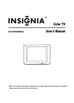
1
TeraPac User Operation and Maintenance Guide MaxVision Corporation 495 Production Avenue Madison, AL 35758, USA Part Number: 209-0029-0 ii TeraPac User Operation and Maintenance Guide Warranties and Liabilities MaxVision Corporation warrants that the Product, in the course of its normal use, will conform to MaxVision's specifications and be free from defects in material and workmanship for a period of twelve (12) months from the date of the original sale. Such warranty commences on the purchase date appearing on the invoice. The original end user is entitled to customer support through telecommunication during normal MaxVision business hours and email support to be responded to as support staff are available. Such support shall be limited to hardware operations and the software required operating such hardware. Upon written request and subject to the availability of MaxVision personnel, additional support may be provided by MaxVision in its sole discretion on a time and materials basis. Limited Warranty for Software. MaxVision warrants to the original end user only that the Software as delivered at the time of purchase will perform in MaxVision hardware, and that the original diskettes or compact disks are free from defects in material and workmanship under normal use, for a period of thirty (30) days from the date of original sale, provided the Software is used with a MaxVision unit. MaxVision makes no warranty that the Software will work in combination with any hardware or software products provided by third parties, that the operation of the Software will be uninterrupted or error-free, or that all defects in the Software will be corrected. This limited warranty is void if failure of the Software has resulted from accident, abuse, or misapplication. MaxVision's entire liability, and your sole and exclusive remedy shall be, at MaxVision's option, either to (a) correct or help you work around or avoid a reproducible Error or (b) replace defective diskettes or compact disks. Any replacement Software will be warranted for the remainder of the original Limited Software Warranty Period. Limited Warranty for the Product. MaxVision warrants to the original end user only that all Products sold by MaxVision will be free from defects in material and workmanship and conform substantially to the applicable standards set forth in the Documentation, under normal use, for a period of 365 days from the date of original sale. This limited warranty is void if failure of the Product has resulted from accident, abuse, or misapplication. If MaxVision confirms a Product is defective after you have obtained a Return Materials Allowance Number for such Product and, at your expense, have returned the Product to MaxVision for inspection, MaxVision will, at its election, repair or replace such Product at no charge to you. Replacement Product may be either new or remanufactured. In the event that the Product returned is not defective, you will be responsible for freight costs for return shipment to you. The foregoing warranty shall not apply to Product that has been (a) damaged by accident, Acts of God, shipment, improper installation, abnormal physical or electrical stress, misuse or misapplication, as determined by MaxVision in its sole reasonable discretion, or (b) modified without MaxVision's express written acceptance of such modification for warranty purposes. MaxVision reserves the right to charge additional fees for repairs or replacements performed outside the Warranty Period. Any replaced or repaired components, subassemblies or units as well as spare parts are warranted for thirty (30) days or the remainder of the original warranty period, whichever is longer. MaxVision shall not be responsible for any software, firmware, information or memory data of yours contained in, stored on, or integrated with any Products returned to MaxVision pursuant to any warranty under this Agreement. Disclaimer of Warranties. EXCEPT AS SPECIFICALLY PROVIDED ABOVE, NEITHER MAXVISION NOR ITS LICENSORS OR SUPPLIERS PROVIDES ANY WARRANTY OF ANY KIND FOR THE SOFTWARE OR THE PRODUCT, WHETHER EXPRESS, IMPLIED, STATUTORY OR OTHERWISE, INCLUDING BUT NOT LIMITED TO WARRANTIES OF MERCHANTABILITY, FITNESS FOR A PARTICULAR PURPOSE, AND NON-INFRINGEMENT OF THIRD PARTY RIGHTS. EXCEPT AS SET FORTH IN THIS AGREEMENT, THE ENTIRE RISK AS TO THE QUALITY AND PERFORMANCE OF THE SOFTWARE AND THE PRODUCT IS WITH YOU. If a disclaimer of implied warranties is not permitted by law, the duration of any such implied warranty is limited to ninety (90) days from the date of purchase by the original end user. Some jurisdictions do not allow the exclusion of implied warranties or limitations on how long an implied warranty may last, so such limitations or exclusions may not apply to you. This limited warranty gives you specific legal rights, and you may also have other rights which vary from jurisdiction to jurisdiction. Liability Exclusions and Limitations. IN NO EVENT SHALL MAXVISION OR ITS LICENSORS OR SUPPLIERS BE LIABLE FOR ANY INDIRECT, SPECIAL, INCIDENTAL, EXEMPLARY OR CONSEQUENTIAL DAMAGES OF ANY KIND (INCLUDING LOST PROFITS, LOSS OF USE OR INTERRUPTION OF BUSINESS), OR FOR LEGAL FEES, ARISING OUT OF THE USE OF THE SOFTWARE OR THE PRODUCT, REGARDLESS OF THE FORM OF ACTION, WHETHER IN CONTRACT, TORT (INCLUDING NEGLIGENCE), STRICT PRODUCT LIABILITY OR OTHERWISE, EVEN IF MAXVISION OR ITS LICENSORS OR SUPPLIERS HAVE BEEN ADVISED OF THE POSSIBILITY OF SUCH DAMAGES. IN NO EVENT WILL COMPANY'S AGGREGATE LIABILITY HEREUNDER EXCEED THE PURCHASE PRICE PAID BY YOU. This limitation shall apply notwithstanding any failure or inability to provide the limited remedies set forth above. Some jurisdictions do not allow the exclusion or limitation of incidental or consequential damages, so the above limitation(s) or exclusion(s) may not apply to you. TeraPac User Operation and Maintenance Guide iii Proprietary Rights-Contracts with Certain U.S. Government Agencies. If the Software is acquired under the terms of a Department of Defense or civilian agency contract, the Software is "commercial item" as that term is defined at 48 C.F.R. 2.101 (Oct. 1995), consisting of "commercial computer software" and "commercial computer software documentation" as such terms are used in 48 C.F.R. 12.212 of the Federal Acquisition Regulations and its successors and 48 C.F.R. 227.7202-1 through 227.7202-4 (June 1995) of the DoD FAR Supplement and its successors. All U.S. Government end users acquire the Software with only those rights set forth in this Agreement. Export Restrictions. You acknowledge that the laws and regulations of the United States restrict the export and re-export of certain commodities and technical data of United States origin, including the Product and the Software, in any medium. You agree that you will not knowingly, without prior authorization if required, export or re-export the Software or the Product in any medium without the appropriate United States and foreign government licenses. Severability. You acknowledge and agree that each provision of this Agreement that provides for a disclaimer of warranties or an exclusion or limitation of damages represents an express allocation of risk, and is part of the consideration of this Agreement. Invalidity of any provision of this Agreement shall not affect the validity of the remaining provisions of this Agreement. General. This Agreement is the entire agreement between you and MaxVision relative to the Product and the Software, and supersedes all prior written statements, proposals or agreements relative to its subject matter. It may be modified only by a writing executed by an authorized representative of MaxVision. No MaxVision reseller or sales representative is authorized to make any modifications, extensions or additions to this Agreement. This Agreement is governed by the laws of the State of Alabama without application of the principles of conflicts or choice of laws. The application of the United Nations Convention on Contracts for the International Sale of Goods to this Agreement is expressly excluded. Copyright The materials in this document are the copyrighted works of MaxVision Corporation, copyright © 2004. All rights reserved. Email [email protected] for permission to duplicate and otherwise re-use. Trademarks MaxVision, and MaxPac are registered trademarks, and MaxPro and TeraPac are trademarks, of MaxVision Corporation. Microsoft and Windows are registered trademarks of Microsoft Corporation. Intel and Pentium are registered trademarks and Xeon is a registered trademark of Intel Corporation. Other trademarks and registered trademarks are the property of their respective owners. Regulatory Approvals EN60950, EN55024, EN55022, FCC, Part 15, EN61000-3-2 & EN61000-3-3. Warnings Changes or modifications to this device that are not approved by the party responsible for compliance could void the user’s authority to operate the equipment. To reduce the risk of electrical shock, do not attempt to open the device unless instructed to do so. Do not use any tool for purposes other than instructed. A Lithium Ion battery is included with the system motherboard. This battery is used for the Real Time Clock (RTC) circuit. The expected lifetime of the battery is approximately 5 years. There is a danger of explosion if this battery is incorrectly replaced. Replace only with the same or equivalent type recommended by the motherboard manufacturer. Dispose of used batteries according to the manufacturer’s instructions. iv TeraPac User Operation and Maintenance Guide Contents Legal and Related Information Warranties and Liabilities .....................................................................................................................................ii Copyright .............................................................................................................................................................iii Trademarks .........................................................................................................................................................iii Regulatory Approvals ..........................................................................................................................................iii Warnings .............................................................................................................................................................iii Chapter 1: Introduction and Very Important (Must-Read) Information! ............................................................. 1 Very Important Information! ................................................................................................................................. 2 Documentation Conventions ............................................................................................................................... 2 Chapter 2: Unpacking your TeraPac and Connecting it to a MaxPac ................................................................ 3 Unpacking and Setting-up Your MaxPac ............................................................................................................ 4 Inspect the TeraPac Shipment ............................................................................................................................ 4 Unpacking the TeraPac ....................................................................................................................................... 4 Location and Power Requirements ..................................................................................................................... 6 Setting-Up Your TeraPac .................................................................................................................................... 6 Chapter 3: Powering-up a New MaxPac/TeraPac Combo .................................................................................... 9 Before You Start ................................................................................................................................................ 10 Powering-up Your MaxPac/TeraPac Combo .................................................................................................... 10 Chapter 4: Adding a New TeraPac to an Existing MaxPac ................................................................................ 13 Before You Start ................................................................................................................................................ 14 Powering-up Your MaxPac/TeraPac Combo .................................................................................................... 14 Chapter 5: Recovering From Powering-Up a MaxPac Without Its TeraPac ..................................................... 37 The Recovery Process ...................................................................................................................................... 38 Chapter 6: Detecting, Isolating, and Replacing a Failed TeraPac Disk ............................................................ 45 The Detection, Isolation, and Replacement Process ........................................................................................ 46 Appendix A: Contacting MaxVision Support (RMA and Serial Numbers)........................................................ 57 Repairing/Replacing Products/Accessories ...................................................................................................... 57 Contacting Technical Support and RMA Numbers ........................................................................................... 57 Next Business Day Delivery/On-site Service for Parts...................................................................................... 57 TeraPac User Operation and Maintenance Guide Chapter 1: Introduction and Very Important (Must-Read) Information! 1 2 TeraPac User Operation and Maintenance Guide Very Important Information! RAID Arrays in general – and RAID controllers in particular – can be somewhat tricky to work with. It is very easy to lose your data – and your operating system – if you execute an incorrect sequence of commands. Thus, unless you are very experienced in the use of the MegaRAID SCSI controller card and its BIOS-level setup utility, it is strongly recommended that you follow the step-by-step instructions provided in this manual. In particular, note that once you have a MaxPac and TeraPac that have been mated (power-up and initialized) together – which is the way a new MaxPac/TeraPac combo arrive when you purchase them together – you should never subsequently power-up the MaxPac without having the TeraPac connected to it. (In the unfortunate event that you do power-up the MaxPac without having the TeraPac connected to it, see Chapter 5 in this manual for details on how to recover from this situation.) Documentation Conventions Icons The information icon is used to annotate important information. The exclamation icon is used to annotate cautionary information. Italics font is used for emphasis, book titles, commands, and path and file names. Bold may be used to emphasize text, highlight menu items, and denote the titles of dialog boxes. Menu > Command identifies the path used to select a menu command. Courier font is used for program listings and for any text messages that the software displays on the screen. Note: describes important information, warnings, or unique commands. “Select” means click the left mouse button on the indicated item. “Click-left” (or just “click”) means click the left mouse button on the indicated item. “Click-middle” means click the middle mouse button on the indicated item. “Click-right” means click the right mouse button on the indicated item. “Double-click” means click twice consecutively with the left mouse button. “Drag-left” (or just “drag”) means press and hold the left mouse button on the indicated item, then move the cursor (pointer) to the destination and release the button. “Shift-click-left” means press and hold the <Shift> key then click the left mouse button on the indicated item. “Ctrl-click-left” means press and hold the <Ctrl> key then click the left mouse button on the indicated item. Fonts TeraPac User Operation and Maintenance Guide Chapter 2: Unpacking your TeraPac and Connecting it to a MaxPac 3 4 TeraPac User Operation and Maintenance Guide Unpacking and Setting-up Your MaxPac Unpack your MaxPac X-Class system and connect its cables (power, mouse, keyboard, and network) as described in the MaxPac X-Class User Operation and Maintenance Guide. Note: Do NOT power-up your MaxPac until you have connected it to the TeraPac as discussed later in this Chapter. Also, in the case of dual- or triple-display systems, do not unfold the display screens at this time (wait until after you have connected the TeraPac to the MaxPac). Inspect the TeraPac Shipment TeraPac systems are packaged to withstand the roughest of treatment during shipping. Any boxes, foam core padding, and anti-static bags should be stored safely away in case you need to ship the system for any reason in the future. Inspect the box the system arrived in. If there is any unusual damage to the box, make note of the damage on the delivery form and contact MaxVision support (see Appendix A for more details). Unpacking the TeraPac TeraPac units are always shipped inside an associated Pelican case, which weighs 22 lbs. Depending on the configuration of your TeraPac – which can contain from three to eight disk drives, each weighing 2 lbs – the TeraPac/Pelican combo will weigh between 48 lbs and 58 lbs (including the packaging). If you are unable to lift this weight safely, you should obtain assistance in unpacking and moving the system. 1) Place the cardboard packing box containing the Pelican case and the TeraPac unit on the floor. 2) Clear an area on a desk or table on which to place the TeraPac system. 3) Carefully cut the tape on top of the outer cardboard packing box and open the box (Figure 2-1). Figure 2-1. Open the outer packing box 4) Have two people (one on each side) lift the Pelican case. Keeping your back straight, bending at the knees and using your legs as much as possible, take the Pelican case out of the box. 5 TeraPac User Operation and Maintenance Guide Note: In order to raise or lower the handle on the Pelican case, use your thumb to slide the release catch to the right (if looking toward the back of the case as shown in Figure 2-2). Figure 2-2. Use the release catch to operate the handle on the Pelican case 5) Place the Pelican case flat on its back on the floor and open it (Figure 2-3). 6) Lift the TeraPac out of the Pelican case (with the aid of a colleague if necessary) and place it on the desk next to the main MaxPac system (Figure 2-4). Figure 2-3 Figure 2-4 6 TeraPac User Operation and Maintenance Guide Location and Power Requirements Location Your TeraPac unit needs to be positioned in a location with the capacity to safely support the main MaxPac X-Class system plus least 26 lbs to 36 lbs depending on the TeraPac configuration. The unit should be unobstructed so as to permit the free flow of cooling air through the intake and exhaust vents. Power Requirements TeraPac X-Class power supplies are auto-sensing 100 to 240 VAC, 50 to 60Hz units. Ensure that the supplied power is sufficient, stable, and without spikes or surges for operation of your TeraPac and other required equipment. Setting-Up Your TeraPac Note: The following discussions assume that your main MaxPac X-Class system is already equipped with a MegaRAID card. However, if you purchased your TeraPac as a separate unit, you may need to add a MegaRAID card to the MaxPac before proceeding with the rest of these instructions (see Chapter 4 for more details). 1) Observe the two black knurled thumbscrews on either side of the case (Figure 2-4). Unscrew these screws (Figure 2-5), pull the cover away from the main unit, and lay it on the desk (Figure 2-6). Figure 2-5 Figure 2-6 7 TeraPac User Operation and Maintenance Guide 2) Insert your thumb and index finger into the two holes located toward the center of the inside cover (Figure 2-7) and lift this cover away to reveal the TeraPac’s data/control cable and power cable (Figure 2-8). Figure 2-7 Figure 2-8 3) Now pull the right-hand thumbscrew out from the main case and slide the protective panel out of the way to reveal the data/control and power connectors (Figure 2-9). 4) Turn the TeraPac around such that its connectors face the MaxPac system (Figure 2-10). Figure 2-9 Figure 2-10 8 TeraPac User Operation and Maintenance Guide 5) Plug one end of the TeraPac’s data/control cable into the main MaxPac system (Figure 2-11). Note: Make sure that you tighten the jack screws so as to hold the connector firmly in place. 6) Plug the other end of the data/control cable into the TeraPac (Figure 2-12). Note: Make sure that you tighten the jack screws so as to hold the connector firmly in place. Figure 2-11 Figure 2-12 7) Connect the TeraPac’s main power cable (Figure 2-13) and plug the other end into an appropriate power supply. Figure 2-13 Note: The TeraPac doesn’t have an On/Off power switch, because its power-up state is automatically controlled by the MegaRAID controller via the TeraPac’s data/control cable. TeraPac User Operation and Maintenance Guide Chapter 3: Powering-up a New MaxPac/TeraPac Combo 9 10 TeraPac User Operation and Maintenance Guide Before You Start The instructions in this chapter assume that you have just taken delivery of a new MaxPac/TeraPac combo and that you are about to power them up for the very first time. 1) Unpack your MaxPac X-Class system and connect its cables (power, mouse, keyboard, and network) as described in the MaxPac X-Class User Operation and Maintenance Guide. Note: Do NOT power-up your MaxPac until you have connected it to the TeraPac as discussed later in this Chapter. Also, in the case of dual- or triple-display systems, do not unfold the display screens at this time (wait until after you have connected the TeraPac to the MaxPac). 2) Unpack your TeraPac unit and connect it to the MaxPac as described in Chapter 2 of this manual. 3) In the case of dual- or triple-display MaxPac systems, unfold the display screens at this time. Powering-up Your MaxPac/TeraPac Combo The following instructions assume that the system has been configured such that one channel of the MegaRAID card is controlling an internal SCSI disk (the main system disk) on one of its channels and the external TeraPac RAID array on its other channel. 1) Power-up the MaxPac as discussed in the MaxPac X-Class User Operation and Maintenance Guide. Observe that the BIOS boot sequence should reflect the fact that two logical drives have been found on the host adapter as shown in Figure 3-1 (the main point here is that you shouldn’t see any error messages). Figure 3-1 Note: The TeraPac doesn’t have an On/Off power switch, because its power-up state is automatically controlled by the MegaRAID controller via the TeraPac’s data/control cable. 2) Power the system all the way up into Windows®, enter your Windows license information, and register your operating system as discussed in the MaxPac X-Class User Operation and Maintenance Guide. 3) Right-click on the My Computer icon on your desktop, and then select (left-click) the Manage item from the ensuing pop-up menu. 4) Click the ‘+’ symbol next to the Storage item (if this item is in its collapsed state) in the lefthand navigation pane, and then select the Disk Management item. You should see two disk drives similar to those shown in Figure 3-2. TeraPac User Operation and Maintenance Guide Note: In this example, Disk 0 (drive C:) is the main system disk, while Disk 1 (drive E:) is the TeraPac RAID array. Figure 3-2 5) It is recommended that you copy a few large files and folders from the main system drive to the TeraPac array to ensure that everything is working as expected (don’t forget to delete these files from the TeraPac when you have completed your tests). Note: Whenever you wish to use your MaxPac in the future, ensure that your TeraPac has power and is connected to the MaxPac before powering-up the MaxPac. 11 12 TeraPac User Operation and Maintenance Guide THIS PAGE LEFT INTENTIONALLY BLANK TeraPac User Operation and Maintenance Guide Chapter 4: Adding a New TeraPac to an Existing MaxPac 13 14 TeraPac User Operation and Maintenance Guide Before You Start The instructions in this chapter assume that you have just taken delivery of a new TeraPac RAID array that you wish to use with an existing MaxPac X-Class system. In this case, there are many different configuration possibilities; for example: a) Your MaxPac may have an IDE hard drive as its main system disk. In this case, your TeraPac will be shipped to you with an associated MegaRAID SCSI control card. You should first insert this PCI card into your MaxPac as discussed in the MaxPac XClass User Operation and Maintenance Guide. b) Your MaxPac may have a SCSI hard drive as its main system disk, where this disk has its own dedicated SCSI card. In this case, your TeraPac will be shipped to you with an associated MegaRAID SCSI control card. You should first insert this PCI card into your MaxPac as discussed in the MaxPac XClass User Operation and Maintenance Guide. Note: Theoretically, you could remove the existing SCSI card from the MaxPac system and use one of the channels from the MegaRAID card to control the internal system disk. However, this is NOT recommended (this option should only be exercised in the case of an overwhelming need to do s0, such as a lack of available PCI slots). c) Your MaxPac may have a SCSI hard drive as its main system disk, and this disk may be driven by one channel of a MegaRAID SCSI control card, in which case the other channel is free to be used to control the external TeraPac RAID array. The discussions and images in the rest of this chapter assume that your system is configured as described in option c). This means that the operating system disk is visible on one of the channels, which would not be the case with regards to options a) and b). 1) Unpack your MaxPac X-Class system. If this system does not already contain a MegaRAID card, then insert this card – which will be shipped with your TeraPac – into your MaxPac as discussed in the MaxPac X-Class User Operation and Maintenance Guide. Then connect the MaxPac’s cables (power, mouse, keyboard, and network) as described in the MaxPac X-Class User Operation and Maintenance Guide. Note: Do NOT power-up your MaxPac until you have connected it to the TeraPac as discussed later in this Chapter. Also, in the case of dual- or triple-display systems, do not unfold the display screens at this time (wait until after you have connected the TeraPac to the MaxPac). 2) Unpack your TeraPac unit and connect it to the MaxPac as described in Chapter 2 of this manual. 3) In the case of dual- or triple-display MaxPac systems, unfold the display screens at this time. Powering-up Your MaxPac/TeraPac Combo 1) Power-up the MaxPac (we are going to perform a quick “sanity check” to prove that the MaxPac does not yet see the TeraPac’s RAID array). Note: The TeraPac doesn’t have an On/Off power switch, because its power-up state is automatically controlled by the MegaRAID controller via the TeraPac’s data/control cable. TeraPac User Operation and Maintenance Guide 15 2) Right-click on the My Computer icon on your desktop, and then select (left-click) the Manage item from the ensuing pop-up menu. 3) Click the ‘+’ symbol next to the Storage item (if this item is in its collapsed state) in the lefthand navigation pane, and then select the Disk Management item. Observe that, in the case of this particular configuration, the system currently only recognizes the main operating system disk (the C: drive) and the CD-DVD (the D: drive) as shown in Figure 4-1. Figure 4-1 4) Power-down the MaxPac and then start the power-up sequence again (be prepared to press the <Ctrl>M keys – that is, press the <Ctrl> key and the ‘M’ key at the same time – as discussed in the following notes. 5) Observe the BIOS reporting that it is spinning up the SCSI drives, followed by messages reporting that the MegaRAID controller has detected only one logical drive (this is our system disk) as shown in Figure 4-2. Note: The reason the MegaRAID card detects a logical drive at this stage is that we are assuming that this card was already being used to control the system drive. If the MegaRAID card has just been installed into a system with and ISA disk for a system drive (or with a SCSI disk being controlled by its own dedicated SCSI card), then it won’t detect any logical drives at this stage. Figure 4-2 16 TeraPac User Operation and Maintenance Guide 6) Pres the <Ctrl>M keys as soon as you see the message inviting you to do so, which will result in you being placed in the MegaRAID configuration utility. 7) Use the Up/Down arrow keys to highlight the “Configure” item in the main menu (Figure 4-3). Figure 4-3 8) Press the <Enter> key to select this option. 9) Use the Up/Down arrow keys to highlight the “View/Add Configuration” item in the ensuing menu (Figure 4-4). Figure 4-4 10) Press the <Enter> key to select this option. TeraPac User Operation and Maintenance Guide 17 11) Observe that the status bar at the bottom of the screen indicates that the system is being scanned for drives. When the scan has been performed, the results are displayed as shown in Figure 4-5. Figure 4-5 12) In this particular example configuration, the MegaRAID controller has detected the operating system disc on Channel 2 on the right-hand side of the screen (the status of this disk is shown as being Online). The controller has also found the three disks in our TeraPac on Channel 1 on the left-hand side of the screen (the status of these disks is shown as being Ready). Note: Any disks in the main MaxPac system are assigned numbers from 0 through 7. By comparison, the disks in the TeraPac are always numbered starting at 8. The minimum number of disks in a TeraPac are three (because this is the smallest number that can support RAID 5), in which case these would be numbered 8, 9, and 10. The maximum number of drives is eight, which will be numbered from 8 to 15. However, the display above shows only drives 0 through 6 on the right-hand side and drives 8 through 14 on the left-hand side. In the case of TeraPac units that do have a full complement of eight disks, the “hidden” drive (number 15) can be seen by using the Up/Down arrow keys to scroll through the drives to the bottom of the list, at which point the list will scroll up to reveal the hidden drive. 13) Use the Up/Down arrow keys to highlight the first drive (drive 8 shown Red in Figure 4-5 above), then press the <Space> key to select this drive. Observe that the status of this drive is changed to Online, it starts flashing. 14) Use the Up/Down arrow keys to highlight the next drive (drive 9 shown Red in Figure 4-6 below). 18 TeraPac User Operation and Maintenance Guide Figure 4-6 15) Press the <Space> key to select this drive. Repeat this process to select the remaining drive as shown in Figure 4-7 (you will, of course, have to repeat this process more times if you have more disks in your TeraPac). Figure 4-7 16) Once all of the drives are shown as being Online (and blinking), press the <Enter> key to end/establish the array (the disks will stop blinking) and then press the <F10> key to access the Select Configurable Arrays dialog as shown in Figure 4-8). TeraPac User Operation and Maintenance Guide Figure 4-8 Note: Any disks in the main MaxPac system are assigned numbers from 0 through 7. By comparison, the disks in the TeraPac are always numbered starting at 8. The minimum number of disks in a TeraPac are three (because this is the smallest number that can support RAID 5), in which case these would be numbered 8, 9, and 10. The maximum number of drives is eight, which will be numbered from 8 to 15. 17) Press the <Space> key to select the required array, which will turn from Gray (as shown in Figure 4-8) to Green (as shown in Figure 4-9). Figure 4-9 18) Press the <F10> key to configure the selected array, which will result in the Logical Drives Configured dialog (Figure 4-10). 19 20 TeraPac User Operation and Maintenance Guide Figure 4-10 19) From the area in the lower left-hand side of the screen we can see that Logical Drive 02 is currently selected. Also, that the default RAID level that will be applied is RAID 5. If you are happy with this RAID level, proceed to step (21). Alternatively, if you wish to change this RAID level, use the Up/Down arrow keys to highlight the RAID item (as shown in Figure 4-10). Next, press the <Enter> key to access the RAID Level sub-dialog, and use the Up/Down arrow keys to highlight the required RAID level (we’ve decided to keep RAID 5 as shown in Figure 4-11). Figure 4-11 20) Click the <Enter> key to accept the selected RAID level. 21) Use the Up/Down arrow keys to highlight the Accept item (Figure 4-12). TeraPac User Operation and Maintenance Guide Figure 4-12 22) Press the <Enter> key to select this item. Observe the Save Configuration sub-dialog that appears. Use the Up/Down arrow keys to highlight the required Yes item (Figure 4-13). Figure 4-13 23) Press the <Enter> key to confirm this selection, which will result in the Configuration is Saved – Press Any Key To Continue dialog appearing on the screen (Figure 4-14). 21 22 TeraPac User Operation and Maintenance Guide Figure 4-14 24) As the dialog suggests, you may press any key to continue, which will return you to the View/Add Configuration dialog (Figure 4-15). Figure 4-15 25) As we now wish to verify our configuration, press the <Enter> key to select this option. Observe the system scanning the disks as reported in the status bar at the bottom of the window. The system will eventually report that all of the disks are now officially online (Figure 4-16). TeraPac User Operation and Maintenance Guide 23 Figure 4-16 26) Press the <F3? Key to see the logical drives, which will result in the Logical Drives Configured dialog appearing on the screen (Figure 4-17). Figure 4-17 27) In the case of our example configuration, logical drive 1 is the system disk with a RAID level of 0, while logical drive 2 is our TeraPac array with a RAID level of 5 (make a note of the corresponding values on your system for future reference). 28) Now we wish to make sure that the system still plans to boot up off the main operating system disk, so pPress the <Esc> key one or more times until you reach the Configure menu, then use the Up/Down arrow keys to highlight the Specify Bootable Logical Drive item (Figure 4-18). 24 TeraPac User Operation and Maintenance Guide Figure 4-18 29) Press the <Enter> key to select this item, which will result in the Logical BootDrive sub-dialog appearing at the bottom of the screen (Figure 4-19). Figure 4-19 30) Use the numeric keypad to specify the number of the logical drive from whence you wish the system to boot (logical drive 1 – which equates to the main system drive – in the case of this example configuration), then press the <Enter> key to accept this value. 31) Press the <Esc> key repeatedly until you reach the main Management menu, then use the Up/Down arrow keys to highlight the Initialization item (Figure 4-20). TeraPac User Operation and Maintenance Guide Figure 4-20 32) Press the <Enter> key to select this item. 33) In lower left-hand side of the ensuing dialog is the Logical Drives sub-dialog. Use the Up/Down arrow keys to highlight the TeraPac array (logical drive 2 in this example configuration) as shown in Figure 4-21. Figure 4-21 34) Press the <Space> key to select this drive, which will turn the text Yellow to show that it’s been selected (Figure 4-22). 25 26 TeraPac User Operation and Maintenance Guide Figure 4-22 35) Now press the <F10> key to commence the initialization, which will first cause the Initialize Yes/No sub-dialog to appear. Use the Up/Down keys to select the Yes option as shown in Figure 4-23. Figure 4-23 36) Press the <Enter> key to confirm your selection, which will result in a real-time progress report being displayed on the screen (Figure 4-24). TeraPac User Operation and Maintenance Guide Figure 4-24 37) When the progress reaches 100%, you will be presented with the Press Any Key To Continue message in the status bar at the bottom of the screen (Figure 4-24) … so press any key to continue. 38) Press the <Esc> key repeatedly until you are presented with the Exit dialog, and then use the Up/Down arrow keys to select the Yes option (Figure 4-25). Figure 4-25 39) Press the <Enter> key to confirm this selection. 40) When you are presented with a message that the configuration has changed and you need to press the <Ctrl><Alt><Delete> keys to reboot …. press the Ctrl><Alt><Delete> keys to reboot. This time, when the system does start to reboot, you will see the MegaRAID controller report that it now finds two logical drives as part of the system (Figure 4-26). 27 28 TeraPac User Operation and Maintenance Guide Figure 4-26 41) Allow the system to boot all the way into Windows. 42) Right-click on the My Computer icon on your desktop, and then select (left-click) the Manage item from the ensuing pop-up menu. 43) Click the ‘+’ symbol next to the Storage item (if this item is in its collapsed state) in the lefthand navigation pane, and then select the Disk Management item. As we have a newly initialized array, the Initialize and Convert Disk Wizard should automatically appear. If you draw this dialog out of the way for a moment, you should see two disk drives similar to those shown in Figure 4-27. Figure 4-27 Note: In this example, Disk 0 (drive C:) is the main system disk, while Disk 1 (with no drive letter yet assigned) is the TeraPac RAID array, which – as far as the operating system in concerned – is Unknown, Not Initialized, and Unallocated. 44) We now return to the Initialize and Convert Disk Wizard as shown in Figure 4-28. TeraPac User Operation and Maintenance Guide Figure 4-28 45) Click the Next button, which will result in a dialog prompting you to select the disk to be initialized (Figure 29). Ensure that the drive number associated with the TeraPac is selected (this is drive 1 in our example configuration as we discovered in Figure 27). Figure 4-29 46) Click the Next button, which will result in a dialog prompting you to select the disk you wish to convert (Figure 30). Ensure that the drive number associated with the TeraPac is selected (once again, this is drive 1 in our example configuration as we discovered in Figure 27). 29 30 TeraPac User Operation and Maintenance Guide Figure 4-30 47) Click the Next button, which will result in the Completing dialog (Figure 4-31). Figure 4-31 48) Click the Finish button to complete the process. If you now turn your attention back to the Computer Management window, you will see that Disk 1 (or the equivalent on your system) is now shown as being Dynamic and Online. However, it is as yet Unallocated, which means that it has no drive letter, it is not formatted, and it has no partitions (Figure 4-32). TeraPac User Operation and Maintenance Guide 31 Figure 4-32 49) Observe that in Figure 4-32, the right-hand area associated with Disk 0 – the C: drive – is shown with diagonal lines. Click your mouse in the corresponding area associated with Disk 1, to see that become shaded/selected (Figure 4-33). Figure 4-33 50) Now right-click in this shaded area and select (left-click) the New Volume item in the ensuing popup dialog. This will result in the New Volume Wizard appearing on your screen (Figure 4-34). 32 TeraPac User Operation and Maintenance Guide Figure 4-34 51) Click the Next button, which will result in a dialog prompting you to select the type of volume you wish to create (Figure 4-35). Ensure that the Simple option is selected. Figure 4-35 TeraPac User Operation and Maintenance Guide 33 52) Click the Next button, which will result in a dialog prompting you to select the disks and set the disk size for this volume (Figure 4-36). Ensure that Disk 1 is selected. Figure 4-36 53) Click the Next button, which will result in a dialog prompting you to assign a drive letter (Figure 4-37). It is recommended that you accept whatever default the system recommends (E: in this case), but you may change this if you wish. Figure 4-37 54) Click the Next button, which will result in a dialog prompting you format the disk (Figure 4-38). It is recommended that you set the File System to NTFS, set the Allocation Unit Size to Default, 34 TeraPac User Operation and Maintenance Guide and rename the Volume Label to TeraPac (or some other appropriate name). It is also recommended that you check the Quick Format box (unless you are operating under security requirements that oblige you to perform a full format). Figure 4-38 55) Click the Next button to receive the Completing the New Volume dialog (Figure 4-39). TeraPac User Operation and Maintenance Guide Figure 4-39 56) Click the Finish button to complete the formatting operation. In the Computer Management window you will now observe that Disk 1 has now been allocated the E: drive letter and its status changes to Formatting (Figure 4-40). Figure 4-40 35 36 TeraPac User Operation and Maintenance Guide 57) Wait until the status of drive E: changes to Healthy (Figure 4-41), at which point the process is complete. Figure 4-41 58) It is recommended that you copy a few large files and folders from the main system drive to the TeraPac array to ensure that everything is working as expected (don’t forget to delete these files from the TeraPac when you have completed your tests). Note: Whenever you wish to use your MaxPac in the future, ensure that your TeraPac has power and is connected to the MaxPac before powering-up the MaxPac. TeraPac User Operation and Maintenance Guide Chapter 5: Recovering From PoweringUp a MaxPac Without Its TeraPac 37 38 TeraPac User Operation and Maintenance Guide The Recovery Process Once you have mated a TeraPac to a MaxPac, you should always have them connected together when you power-up the MaxPac. If you do happen to forget to connect the TeraPac (or run into a similar circumstance such as failing to have the TeraPac supplied with power, for example), then the MegaRAID controller card will become “confused” when it fails to see the expected configuration. In this Chapter we will walk through the process of recovering from this situation. For the purposes of these discussions, we will assume a system configuration identical to those discussed in Chapters 3 and 4. That is, the MaxPac contains a MegaRAID card with Channel 2 controlling the C: internal system drive and Channel 1 controlling a TeraPac containing three drives. In order to demonstrate the recovery process, we first have to cause the problem situation to occur. 1) Ensure that the system is powered down, disconnect the TeraPac’s data/control cable from the MaxPac, and then power up the MaxPac again. In the boot up sequence, you will see the MegaRAID controller report that SCSI IDs 8, 9, and 10 ob Channel 1 are failing to respond (Figure 5-1). Figure 5-1 2) Unfortunately, the MegaRAID controller doesn’t cause the system to pause and warn you that a potential problem is about to occur. Instead, it allows the system to boot up all the way into Windows, by which time you really do have a problem. Once you are in Windows, right-click on the My Computer icon on your desktop, and then select (left-click) the Manage item from the ensuing pop-up menu. 3) Click the ‘+’ symbol next to the Storage item (if this item is in its collapsed state) in the lefthand navigation pane, and then select the Disk Management item. Not surprisingly, the system reports that it can only find the C: drive at the CD/DVD; the TeraPac simply isn’t there (Figure 5-2). TeraPac User Operation and Maintenance Guide Figure 5-2 4) Power-down the MaxPac, reconnect the TeraPac, and restart the MaxPac power-up sequence (be prepared to press <Ctrl>M as discussed below). Early in the boot-up sequence, the MegaRAID controller will report that it’s found two logical drives, but that one has failed (Figure 5-3). Figure 5-3 5) Press the <Ctrl>M key combination when you are invited to do so, which will bring up the MegaRAID configuration utility interface. 6) Use the Up/Down arrow keys to highlight the Objects item in the Management Menu (Figure 5-4). 39 40 TeraPac User Operation and Maintenance Guide Figure 5-4 7) Press the <Enter> key to select this item, then use the Up/Down keys to highlight the Physical Drive item in the ensuing menu (Figure 5-5). Figure 5-5 8) Press the <Enter> key to select this item. Observe the system scanning the drives, as reported in the status bar in the bottom of the window. Eventually, the system will return the Physical Drive Selection Menu (Figure 5-6). TeraPac User Operation and Maintenance Guide Figure 5-6 9) Observe the three Failed drives associated with Channel 1 on the left-hand side of the screen. These are the drives we have to reestablish without losing and of the data they contain. 10) Use the Up/Down arrow keys to highlight one of the failed drives (its’ usual to start with Drive 8 and work our way up). 11) Press the <Enter> key to select the highlighted drive, then use the Up/Down arrow keys to highlight the Make Online item in the ensuing dialog (Figure 5-7). Figure 5-7 12) Press the <Enter> key to confirm this selection, and observe the pink warning screen that appears as shown in Figure 5-8). 41 42 TeraPac User Operation and Maintenance Guide Figure 5-8 13) Use the Up/Down arrow keys to select the Yes option as shown above, then press the <Enter> key to confirm this selection. This drive is now reported as being Online (Figure 5-9). Figure 5-9 14) Repeat steps (10) through (13) fir the remaining failed drives until all three drives are reported as being back online (Figure 5-10). TeraPac User Operation and Maintenance Guide Figure 5-10 15) Press the <Esc> key repeatedly until you are presented with the Exit dialog, and then use the Up/Down arrow keys to select the Yes option (Figure 5-11). Figure 5-11 16) Press the <Enter> key to confirm this selection. 17) When you are presented with a message that the configuration has changed and you need to press the <Ctrl><Alt><Delete> keys to reboot …. press the Ctrl><Alt><Delete> keys to reboot. 18) Once the system has powered-up into Windows, right-click on the My Computer icon on your desktop, and then select (left-click) the Manage item from the ensuing pop-up menu. 43 44 TeraPac User Operation and Maintenance Guide 19) Click the ‘+’ symbol next to the Storage item (if this item is in its collapsed state) in the lefthand navigation pane, and then select the Disk Management item. This time, the system does find the TeraPac drive as expected (Figure 5-12). Figure 5-12 TeraPac User Operation and Maintenance Guide Chapter 6: Detecting, Isolating, and Replacing a Failed TeraPac Disk 45 46 TeraPac User Operation and Maintenance Guide The Detection, Isolation, and Replacement Process In this Chapter we will walk through the process of recovering from a drive failing in the TeraPac’s RAID array. For the purposes of these discussions, we will assume a system configuration identical to those discussed in Chapters 3 and 4. That is, the MaxPac contains a MegaRAID card with Channel 2 controlling the C: internal system drive and Channel 1 controlling a TeraPac containing three drives. 1) Let’s assume that the third disk in the TeraPac (drive 10) has failed. Power-up the system and observe the MegaRAID report the failed drive (Figure 6-1) Figure 6-1 2) At this point, unless you’ve previously disabled it, a very annoying warning beeper will be trying to alert you to the fact that there is a problem. However, even though a drive has failed, you can continue to use the data on the remaining drives in the array (although it is strongly recommended that you replace the failed drive as soon as possible). If you do wish to keep on using the TeraPac with a failed disk, you will very quickly wish to turn the alarm off, so press <Ctrl><M> when prompted to do so, which will take you into the MegaRAID utility. Once you are in this utility, use the Up/Down arrow keys to highlight the Objects item in the Management Menu (Figure 6-2). Figure 6-2 3) Press the <Enter> key to select this item and then use the Up/Down arrow keys to highlight the Adapter item in the ensuing menu (Figure 6-3). TeraPac User Operation and Maintenance Guide Figure 6-3 4) Press the <Enter> key to select this item and then use the Up/Down arrow keys to highlight the Alarm Control item in the ensuing menu (Figure 6-4). Figure 6-4 5) Press the <Enter> key to select this item and then use the Up/Down arrow keys to highlight the Disable Alarm item in the ensuing menu (Figure 6-5). 47 48 TeraPac User Operation and Maintenance Guide Figure 6-5 6) Press the <Enter> key to select this item and then use the Up/Down arrow keys to highlight the Yes item in the ensuing menu (Figure 6-6). Figure 6-6 7) Press the <Enter> key to confirm this selection. 8) Press the <Esc> key repeatedly until you regress to the main Management Menu, then use the Up/Down arrow keys to highlight the Configure item (Figure 6-7). TeraPac User Operation and Maintenance Guide Figure 6-7 9) Press the <Enter> key to select this item then use the Up/Down arrow keys to highlight the View/Add Configuration item in the ensuing menu (Figure 6-8). Figure 6-8 10) Press the <Enter> key to select this item and observe the system scanning the disks and reporting its progress in the status bar at the bottom of the window. The system eventually presents a summary of the scanned disks showing that it is indeed drive 10 that has Failed in some way (Figure 6-9). 49 50 TeraPac User Operation and Maintenance Guide Figure 6-9 11) Press the <Esc> key repeatedly until you are presented with the Exit dialog, and then use the Up/Down arrow keys to select the Yes option (Figure 6-10). Figure 6-10 12) Press <Enter> to confirm this selection and then, when prompted to do so, press <Control><Alt><Delete> to reboot the system. 13) Once the system has powered-up into Windows, right-click on the My Computer icon on your desktop, and then select (left-click) the Manage item from the ensuing pop-up menu. 14) Click the ‘+’ symbol next to the Storage item (if this item is in its collapsed state) in the lefthand navigation pane, and then select the Disk Management item. Observe that the system continues to display the status of Disk 1 as being Healthy, which it is as far as Windows is concerned (Figure 6-11). 51 TeraPac User Operation and Maintenance Guide Figure 6-11 15) Remember that you can continue to use your TeraPac in the short term, but you should replace the failed drives as soon as possible. Once you are ready to replace the failed drive, power down your system, disconnect the TeraPac, lie it face down on the table, and remove the four screws holding the back cover (Figure 6-12). 16) Lift the cover away to reveal a brass-colored retaining and protection plate (Figure 6-13). Figure 6-12 Figure 6-13 17) Remove all of the screws attaching the brass-colored retaining and protection plate to the hard disks and the rest of the chassis (Figure 6-14). 18) Stand the TeraPac up to provide full access to its internals (Figure 6-15). 52 TeraPac User Operation and Maintenance Guide Figure 6-14 Figure 6-15 19) Observe that TeraPac discs should always follow a common numbering convention as shown in Figure 6-16. 20) From our earlier investigations, we know that disk 10 has failed, so turn the TeraPac around to expose the front size and remove the three screws attaching disk 10 to the chassis (Figure 6-17). 8 9 10 11 12 15 14 13 Figure 6-16 Figure 6-17 21) Gently extract the failed disk from the case, and then remove the four screws holding the cable retention plate to the back of the drive (Figure 6-18). 22) Carefully remove the cable retention plate and store it in a safe place (Figure 6-19). 53 TeraPac User Operation and Maintenance Guide Figure 6-18 Figure 6-19 23) Disconnect the power and data cables from the failed disk and lay it on the desk (Figure 6-20). Figure 6-20 24) Observe the pins at the bottom left of this image. From left to right, the first four pairs of pins have binary weights of 1, 2, 4, and 8. Now observe the two gray jumpers connected to the pin pairs associated with binary weights 2 and 8; combined these equal 10, which is the number of the failed drive. The point is that the replacement drive must be keyed to match the number of the failed drive. 25) Once you have keyed the new drive to match the number of the failed drive, insert the drive into the TeraPac by performing the above steps in reverse order. 26) Reconnect the TeraPac’s power and data/control cables, and then power-up the MaxPac. This time, the MegaRAID controller will report that it finds two logical drives, one of which is Degraded (Figure 6-21). 54 TeraPac User Operation and Maintenance Guide Figure 6-21 27) Press <Ctrl>M when presented with the opportunity to do so, thereby entering the MegaRAID configuration utility. Use the Up/Down keys to highlight the Rebuild item in the main menu (Figure 6-22). Figure 6-22 28) The Rebuild option will bring this drive into the RAID array and reload it with its share of the RAID 5-related data from the other drives in the array. Press the <Enter> key to confirm this selection and observe the system display the current configuration (Figure 6-23). TeraPac User Operation and Maintenance Guide 55 Figure 6-23 29) Use the Up/Down keys to highlight the failed drive and then press the <Space> key to select this drive (it will start flashing to indicate that it has indeed been selected). 30) Press the <F10> key to initiate the rebuild process and use the Up/Down keys to highlight the Yes option in the ensuing menu (Figure 6-24). Figure 6-24 31) Press the <Enter> key to confirm this selection and observe the real-time display showing the progress of the replacement drive being integrated into the array (Figure 6-25). 56 TeraPac User Operation and Maintenance Guide Figure 6-25 32) Press the <Esc> key repeatedly until you are presented with the Exit dialog, and then use the Up/Down arrow keys to select the Yes option (Figure 6-26). Figure 6-26 33) Press <Enter> to confirm this selection and then, when prompted to do so, press <Control><Alt><Delete> to reboot the system. TeraPac User Operation and Maintenance Guide 57 Appendix A: Contacting MaxVision Support (RMA and Serial Numbers) Repairing/Replacing Products/Accessories MaxVision will repair or replace products/accessories due to defects in material or workmanship, or any failure of the hardware system to conform to written specifications. Warranty repairs will be performed at MaxVision’s service center. Any replacement parts/products shall be new or refurbished. Any repaired or replaced product will not extend the original warranty term of the product. Additionally, this warranty period will not be extended as a result of the purchase of any additional parts/products from MaxVision Corporation. Contacting Technical Support and RMA Numbers During the warranty period, MaxVision will provide technical support for hardware diagnosis via email ([email protected]) or the technical support and customer service hotline (800-5335805). If MaxVision’s technical support determines that the product is defective, MaxVision will issue a Return Material Authorization (RMA) number to the customer. The customer is required to ship the product referencing the RMA number on the outside of the original (or equivalent) packaging with a copy of MaxVision’s invoice enclosed. The return shipment must be sent insured and prepaid to MaxVision Corporation 495 Production Avenue Madison, AL 35758 USA MaxVision will ship the repaired or replaced product to the customer with freight prepaid if the customer’s address is within United Stated of America (excluding Alaska, Hawaii, Puerto Rico and U.S. possessions). Shipments to other locations will be shipped at the customers expense. MaxVision must receive notice of all events before the warranty period expires. NOTE: MaxVision will not be responsible for data on the hard-disk drive. Before you ship the product(s) to MaxVision, please back up your data from the hard-disk drive(s)or any other storage device(s) in the product(s). Next Business Day Delivery/On-site Service for Parts For contracts with next business day parts delivery/on-site clauses, in order to ensure receipt of parts by the next business day, the problem must be resolved between the customer and MaxVision’s technical support department before noon, Central time, if parts are available. For calls resolved after noon Central time, the receipt of parts by the customer may take one additional business day.