1
User’s Manual
PG-32200 Series
PG-32400 Series
Pattern Generator
with Logic Analyzer
RevisionⅡ
Software Win98/me/2000/xp/Vista
http://www.clock-link.com.tw
Item Checklist..................................................................................................2
System Requirements .....................................................................................2
Installing Hardware..........................................................................................2
Installing PG-32200 / PG-32400 Series with USB 2.0 cable........................................ 2
LED Display.....................................................................................................2
Installing Software ...........................................................................................3
Guide To Operations .......................................................................................3
Main Screen ....................................................................................................4
Horizontal Scroll Bar........................................................................................5
Hardware Specification....................................................................................6
I/O Pin Location...............................................................................................8
File Menu.........................................................................................................9
View Menu.....................................................................................................10
Setup Menu ...................................................................................................10
Trigger Word..................................................................................................10
External Clock ............................................................................................... 11
Group Edit ..................................................................................................... 11
Mnemonic Edit...............................................................................................12
Initialize (Hardware) ......................................................................................12
Toolbar...........................................................................................................12
Pattern Editor ................................................................................................13
Search Data ..................................................................................................13
State List (Window Menu) .............................................................................14
Color Setup ...................................................................................................15
Pattern4k.la Data Format ..............................................................................16
Window USB Driver Install ............................................................................17
Windows 98/ME USB driver install............................................................................. 17
Windows 2000 USB driver install ............................................................................... 19
Windows XP USB driver install .................................................................................. 22
Windows Vista USB driver install ............................................................................... 25
Technical Support..........................................................................................28
Software Updates..........................................................................................28
1
Item Checklist
1. The PG-32200 / PG-32400 Series Plastic unit.
2. There are 4 models of PG-32200 Series and PG-32400 Series.
□ PG-32200K: (200MHz, 256 K Memory).
□ PG-32200M: (200MHz, 1 Mega Memory).
□ PG-32400K: (400MHz, 256 K Memory).
□ PG-32400M: (400MHz, 1 Mega Memory).
3.
4.
5.
6.
Four harness with color wires and 50 pcs Easy Hook clips.
PG-32200 / PG32400 Series User's Manual X 1.
CD for PG-32200 / PG-32400 Series driver X 1.
USB 2.0 cable X 1 (Mini Type).
System Requirements
In order to use the PG-32200 /PG-32400 Series, the following equipment is necessary:
Computer System: Pentium PC system with at least one USB interface
(USB 1.1 or 2.0 version).
Memory:
A minimum of 256 MB free RAM. 512 MB or 1GB is better.
Mass Storage:
At least one CD drives and hard disk drives.
Display Adapter:
At least one of VGA Adapter (Resolution 1440x900 is better).
Monitor:
Any monitor compatible with the above display adapter.
Operation System: Windows 98/ME/2000/XP.
Installing Hardware
Installing PG-32200 / PG-32400 Series with USB 2.0 cable.
Please follow these instructions for installing the PG-32200 / PG-32400 Series with USB cable.
1. Turn off the computer and all peripherals connected. Remove the computer power cord
from the wall outlet. Locate an available USB (version 1.1 / 2.0) interface.
2. Connect the included USB cable to USB interface.
3. Connect the other end of the USB cable to the PG-32200 / PG-32400 Series USB port.
4. After checking all connections, turn on the computer and peripherals. You are now
ready to install the software.
LED Display
When USB cable connected PG-32XXX is ready the LED color indicate “GREEN”.
When PG-32xxx program running the LED color indicate “YELLOW”.
2
Installing Software
1. Insert the distribution CD into drive E: (hear "E" is CD driver).
2. Run E: \PG-32200\Setup.exe.
3. Follow the on screen instructions.
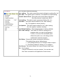
Guide To Operations
When making measurements with the Logic Analyzer, meaningful data can only be
captured with some prior knowledge of the characteristics of the circuit under test.
before initiating any capture cycles, the Logic Analyzer must be configured using
the control program. See the software section later in the manual for instructions on
these procedures. To connect the Logic Analyzer to the test circuit, a series of mini-clips
on the Logic Analyzer Pod for the Logic input channels. The Logic Analyzer has inputs
for 32 channels, At times, it may also be necessary to connect the test circuit to the
computer system itself. This will eliminate more noise in the test application due to
ground level differentials. This is especially true when dealing with high speed timing
analysis. Use a heavy gauge wire to make a connection between the test circuit
ground and the case of the computer.
3
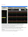
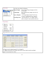
Main Screen
The data is displayed as a timing waveform. Each channel is displayed in it's own color.
Channel names, numeric value of data at each cursor and scrollbars are also in this view.
The window can be zoomed in or out to show just a few samples or the entire buffer.
Data can be displayed on screen as a timing waveform.
Each channel can have a user-specified name and can be displayed in any sequence.
Channels can be also be grouped together into busses and viewed in ASCII, hexadecimal, decimal,
binary, or in user defined mnemonics. Time between V1bar, V2bar, and Trigger
is displayed.
Zoom scales of 1/200X to 50X (horizontal). Indicator of current position of buffer shown
on screen. The color of each channel can be set independently.
4
Horizontal Scroll Bar
This scroll bar is used in conjunction with a selected waveform or cursor.
The Horizontal Scroll Bar will move a selected waveform or cursor left or right in the
Display area.
The Horizontal Scroll Bar works with Display, Logic Analyzer channels, V1Bar, V2Bar,
and Trigger Cursor.
5
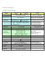
Hardware Specification
PG-32400 Series Specifications
Model
PG-32400K
[512K]
PG-32400M
[2 Mega]
Remark
Pattern update rate
Logic sampling rate
From 1Sa/s to 400 Msa/s
With 1, 2, 5 Sequence
External clock rate
Up to 200 MSa/s
From Ext. clk0 & Ext.clk1 with
standard TTL (1.4V Threshold)
Combine OR, NOR, AND, NAND
32Ch: 256K x 2 /Ch
32Ch: 1M x 2 /Ch
16Ch: 512K x 2 /Ch
16Ch: 2M x 2 /Ch
Ch 0 ~ Ch31 (Pattern + Logic Analyzer.
Number of Channels
GOE ─ (Globe output enable active low).
2 External clock.
Record length
I/O Bandwidth
Input Impedance
Max. input voltage
I/O Type (drive
current, threshold)
Output enable delay
Channel skew
Trigger position
Max. Trigger speed
Trigger Qualify
Power Supply
Net Weight
Size (Dimension)
Accessories
DC to 200 MHz
100 KΩ // 8pF
+10V to -2V
LVC1.5V (10mA, 0.75V)
LVC1.8V (12mA, 0.9V)
LVC2.5V (16mA, 1.2V)
LVC3.3V (20mA, 1.4V)
SSTL2 II 2.5V (16mA, 0 to 2.4V)
SSTL3 II 3.3V (16Ma, 0 to 3V)
Typical < 10 ns
Typical < 200 ps
-67M to 256K / 512K
-67M to 1Mega / 2Mega
200MHz / 5ns
0, 1, x (don't care)
Settings for all digital channels
No External Power Source Require
120 Grams
107mm x 77mm x 16mm
Color wires Harness + clips, USB 2.0 cable
User's Manual, CD driver
6
Total = (256K / 1M) x 2 x 32 Ch
32 Channel Bi-Direction
default to Ext.clk0, Ext.clk1
(OR, NOR, AND, NAND)
With < 30pF load
With 100 Ohm series
Drive current
(Balance source and sink)
Standard Logic I/O.
Input/Output Bi-Direction change
Any position for user defined
Simultaneous trigger
Pattern and Logic channel
From USB Port < 450mA
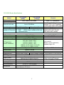
PG-32200 Series Specifications
Model
Pattern update rate
Logic sampling rate
PG-32200K
[256K]
PG-32200M
[1 Mega]
From 1Sa/s to 200 Msa/s
Remark
With 1, 2, 5 Sequence
From Ext. clk0 & Ext.clk1 with
standard TTL (1.4V Threshold)
Combine OR, NOR, AND, NAND
Record length
32Ch: 256K x 2 /Ch
32Ch: 1M x 2 /Ch
Total = (256K / 1M) x 2 x 32 Ch
Ch 0 ~ Ch31 (Pattern + Logic Analyzer.
32 Channel Bi-Direction
Number of Channels
GOE ─ (Globe output enable active low). default to Ext.clk0, Ext.clk1
2 External clock.
(OR, NOR, AND, NAND)
External clock rate
I/O Bandwidth
Input Impedance
Max. input voltage
I/O Type (drive
current, threshold)
Output enable delay
Channel skew
Trigger position
Max. Trigger speed
Trigger Qualify
Power Supply
Net Weight
Size (Dimension)
Accessories
Up to 100 MSa/s
DC to 100 MHz
100 KΩ // 8pF
+10V to -2V
LVC1.5V (10mA, 0.75V)
LVC1.8V (12mA, 0.9V)
LVC2.5V (16mA, 1.2V)
LVC3.3V (20mA, 1.4V)
SSTL2 II 2.5V (16mA, 0 to 2.4V)
SSTL3 II 3.3V (16Ma, 0 to 3V)
Typical < 10 ns
Typical < 200 ps
-67M to 256K / 512K
-67M to 1Mega / 2Mega
100MHz / 10ns
0, 1, x (don't care)
Settings for all digital channels
No External Power Source Require
120 Grams
107mm x 77mm x 16mm
Color wires Harness + clips, USB 2.0 cable
User's Manual, CD driver
7
With < 30pF load
With 100 Ohm series
Drive current
(Balance source and sink)
Standard Logic I/O.
Input/Output Bi-Direction change
Any position for user defined
Simultaneous trigger
Pattern and Logic channel
From USB Port < 450mA
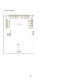
I/O Pin Location
8
File Menu
The File menu offers the following:
Save setting This option saves the current settings to a setting file (.ini).
Save data This option saves a data file (.La) depend on Depth setting.
Transfer data to Excel This option will convert data to Microsoft
Excel by decimal, hexdecimal, ASCII.
Load setting This option loads a previously Setting file (.ini).
Load data This option loads a data file (.La), with a setting
file (.ini) together to viewer memory.
Load pattern This option loads a data file (.La), with a setting
file (.ini) together to pattern memory.
Load Default Setting Reset all parameters to factory defaults.
Auto Load settings Auto load PG-32200.ini setting file on
program start run to set all configuration.
Turns on or turns off the Autoload option.
When this option is on, all settings will be
loaded when start the program.
Print Setup Output style, printer and printer connection.
This option brings up two dialog boxes:
1. Print settings allows you to configure what to output.
2. Print Setup dialog box allows you to configure
Print Screen This option allows you to print Screen (Hard copy).
Exit Exit Program.
Use this command to end your session. You can also use
the Close command on the application Control menu.
9
View Menu
The View menu offers the following:
Channel Height
Select display Channel Height as 20, 24,
28, 32 pixels.
Group Height
Select display Group Height as 24, 28, 32,
36 pixels.
Time or Samples For Timing display, display Time like as
12.34ms, or display how many samples.
Zoom Align from Set cursor Bar {(V1, V2, Trigger, Screen
(left or center)} for zoom operate reference.
Setup Menu
Trigger Word
Set Trigger word for digital channel 31-0 or Group0-3.
The Trigger word backup four Qualify data and four Group data for quickly set digital
trigger. You can setup from V bars.
10
External Clock
Two external clock combine logic OR, AND, not OR, not AND for select.
Group Edit
Edit channel 31-0 for Group Channel, every Group Channel supports 16bits Max.
could be display in hexdecimal, decimal, binary, octadic, ASCII code.
11
Mnemonic Edit
Initialize (Hardware)
This option allows you to restart PG-32200 or PG-32400.
Toolbar
The Go command tells the PG-32200 to start acquiring data when the trigger
conditions are satisfied. Pressed means Start capture, un-pressed means stop capture.
Moves one or more cursors to the display area. These commands are also available by
clicking on the toolbar.
Moves Trigger Bar, V1Bar and V2Bar onto the waveform display area.
Centers waveform display area around V1Bar.
Centers waveform display area around V2Bar.
Centers waveform display area around the Trigger Bar.
12
Edit Pattern data.
Pattern Editor
The Pattern Generation is completely integrated with the PG-32200.
The two operate from the same clock source, whether the internal
clock or the external clock. Patterns can loop continuously, loop until
the Logic Analyzer triggers, or once on the users command.
Allocation of channels between the Logic Analyzer and the Pattern
Generation is in groups of 8 channels. Channels can be all logic
analysis, all pattern generation, or any multiple of eight for pattern
generation with the remaining channels as logic analysis. To select
the configuration, simply change the "Config" in the software.
Pattern generation up to the maximum number of channels of the
PG-32200 is supported, limited only by the number of ports.
Patterns can be edited and defined in this window. It's a visual and
convenient software. At first, must mark a block use mouse right key,
and set High, Low, Invert or
Input: set port (8 channels) to input mode.
Output: set port (8 channels) to Output mode.
Clock: there are 5 rate for select.
Counter: up/down count can be depend on Clock or none.
I²C create: can be create I²C stream, just edit Address , Command,
Data byte. You can also get data for the pattern data by capturing it
from logic channels and copying it to the pattern channels.
Pattern data can also come from data files created by this software
or files that you create yourself.
Search Data
13
Sorting through all your data is easier with our search feature! You can specify a search
pattern, including Don't Care bits, in any shown numeric bases. Then just click on the
forwards or backwards search to find what you are looking for !
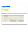
State List (Window Menu)
Channels can be organized into groups and displayed on screen in ASCII, binary, decimal,
hexdecimal, and user defined mnemonics. Channels can be displayed in any sequence.
Time between V1bar, V2bar, and Trigger is displayed.
14
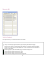
Color Setup
The color of each channel or Group can be set independently.
15
Pattern4k.la Data Format
This is a Pattern data file.
It's buffer length is 4k, total
length is 4kx5=20k.
0000 to 0FFF for Ch[7:0] (Port0)
1000 to 1FFF for Ch[15:8] (Port1)
2000 to 2FFF for Ch[23:16] (Port2)
3000 to 3FFF for Ch[31:24] (Port3)
4000 to 4FFF for Port input/output
bit0: 1=output, 0=input, for port0
bit1: 1=output, 0=input, for port1
bit2: 1=output, 0=input, for port2
bit3: 1=output, 0=input, for port3
16
Window USB Driver Install
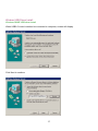
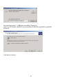
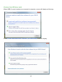
Windows 98/ME USB driver install
When USB2.0 control interface be connected to computer, screen will display
Click Next to continue
17
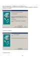
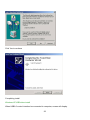
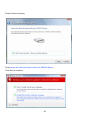
Edit or browse path to ...\USB20driver\win98_ME\gene.inf
(here D: is CD location, dso25216 may be dso29xx or la5000b or pg32200 or pg32400)
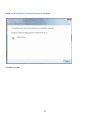
Click Next to continue
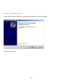
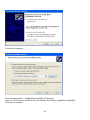
Click Next to continue
Completing install
18
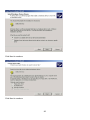
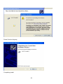
Windows 2000 USB driver install
When USB2.0 control interface be connected to computer, screen will display
Click Next to continue
19
Click Next to continue
Click Next to continue
20
Edit or browse path to ...\USB20driver\win2000_XP\gene.inf
(here F: is CD location, dso25216 may be dso29xx or la5000b or pg32200 or pg32400)
Press OK
Click Next to continue
21
Click Yes to continue
Completing install
Windows XP USB driver install
When USB2.0 control interface be connected to computer, screen will display
22
Click Next to continue
Edit or browse path to ...\USB20driver\win2000_XP\gene.inf
(here E: is CD location, dso25216 may be dso29xx or la5000b or pg32200 or pg32400)
Click Next to continue
23
Press Continue Anyway
Completing install
24
Windows Vista USB driver install
When USB2.0 control interface be connected to computer, screen will display as following:
Press Locate and install driver software (recommended) Continue Anyway
25
Press Continue Anyway
Press Insert the disc that came with your USB2.0 Device
Click Next to continue
26
Press Install this driver software anyway to Continue
Completing install
27
Technical Support
Technical Support can be reached at
克拉克電腦股份有限公司
7F., No: 5. Lane 236, Section 5.
Roosevelt Road. Taipei, 116. Taiwan.
Phone: 886-2-29321685. 29340273. 29335954.
Fax: 886-2-29331687.
Email: [email protected]
Software Updates
Software can be downloaded from our website
Web: www.clock-link.com.tw
Software @copyright
Clock Computer Corp.
7F., No: 5. Lane 236, Section 5.
Roosevelt Road. Taipei, 116. Taiwan.
All Right Reserved
Phone: 886-2-29321685. 29340273. 29335954.
Fax: 886-2-29331687.
Email: [email protected]
28