1
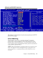
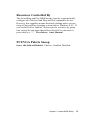
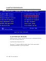
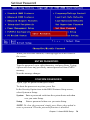
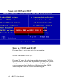
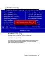
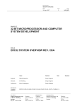
CHAPTER
3
Award BIOS Setup
This chapter describes how to configure
the BIOS for the system.
42
SBC-776 User Manual
Starting setup
The Award BIOS is immediately activated when you first turn on
the computer. The BIOS reads system configuration information in
CMOS RAM and begins the process of checking out the system
and configuring it through the power-on self test (POST).
When these preliminaries are finished, the BIOS seeks an operating
system on one of the data storage devices (hard drive, floppy drive,
etc.). The BIOS launches the operating system and hands control of
system operations to it.
During POST, you can start the Setup program in one of two ways:
1.By pressing Del immediately after switching the system on, or
2.By pressing Del or pressing Ctrl-Alt-Esc when the following
message appears briefly at the bottom of the screen during POST:
TO ENTER SETUP BEFORE BOOT PRESS DEL KEY
If the message disappears before you respond and you still wish to
enter Setup, restart the system to try again by turning it OFF then
ON or pressing the RESET button on the system case. You may
also restart by simultaneously pressing Ctr-Alt-Del. If you do not
press the keys at the correct time and the system does not boot, an
error message appears and you are again asked to
PRESS F1 TO CONTINUE, DEL TO ENTER SETUP
Chapter 3 Award BIOS Setup
43
Setup keys
These keys helps you navigate in Award BIOS:
Up arrow
Down arrow
Left arrow
Right arrow
Esc
PgUP/+
PgDn/F1
F2
F3
F4
F5
F6
F7
F8
F9
F10
44
SBC-776 User Manual
Move to previous item
Move to next item
Move to the item in the left hand
Move to the item in the right hand
Main Menu: Quit and not save changes into
CMOS RAM
Other pages: Exit current page and return to
Main Menu
Increase the numeric value or make
changes
Decrease the numeric value or make
changes
General help, only for Status Page Setup
Menu and Option Page Setup Menu
Item Help
Reserved
Reserved
Restore the previous CMOS value from
CMOS, only for Option Page Setup Menu
Load the default CMOS RAM value from
BIOS default table, only for Option Page
Setup Menu
Load the default
Reserved
Reserved
Save all the CMOS changes, only for Main
Menu
Getting help
Press F1 to pop up a small help window that describes the appropriate keys to use and the possible selections for the highlighted
item. To exit the Help Window press Esc or the F1 key again.
In Case of Problems
If, after making and saving system changes with Setup, you
discover that your computer no longer is able to boot, the Award
BIOS supports an override to the CMOS settings that resets your
system to its default configuration.
You can invoke this override by immediately pressing Insert; when
you restart your computer. You can restart by either using the ON/
OFF switch, the RESET button or by pressing Ctrl-Alt-Delete.
The best advice is to alter only settings that you thoroughly
understand. In particular, do not change settings in the Chipset
screen without a good reason. The Chipset defaults have been
carefully chosen by Award Software or your system manufacturer
for the best performance and reliability. Even a seemingly small
change to the Chipset setup may cause the system to become
unstable.
Chapter 3 Award BIOS Setup
45
Main Setup Menu
Standard CMOS Features
Use this menu for basic system configuration. (Date, time, IDE,
etc.)
Advanced BIOS Features
Use this menu to set the advanced features available on your
system.
Advanced Chipset Features
Use this menu to change the values in the chipset registers and
optimize your system’s performance.
Integrated Peripherals
Use this menu to specify your settings for integrated peripherals.
(Primary slave, secondary slave, keyboard, mouse etc.)
Power Management Setup
Use this menu to specify your settings for power management.
(HDD power down, power on by ring, KB wake up, etc.)
46
SBC-776 User Manual
PnP/PCI Configuration
This entry appears is your system supports PnP/PCI.
PC Health Status
This menu allows you to set the shutdown temperature for your
system.
Frequency/Voltage Control
Use this menu to specify your settings for frequency/ voltage
control.
Load Fail-Safe Defaults
Use this menu to load the BIOS default values for the minimal/
stable performance for your system to operate.
Load Optimized Defaults
Use this menu to load the BIOS default values that are factory
settings for optimal performance system operations. While
AWARD has designated the custom BIOS to maximize performance, the factory has the right to change these defaults to meet
their needs.
Set Supervisor/User Password
Use this menu to set User and Supervisor Passwords.
Save and Exit Setup
Save CMOS value changes to CMOS and exit setup.
Exit Without Saving
Abandon all CMOS value changes and exit setup.
Chapter 3 Award BIOS Setup
47
Standard CMOS Features
This standard setup menu allows users to configure system
components such as the date, time, hard disk drive, floppy drive,
display, and memory. Online help for each field can be accessed
by pressing F1.
Date and Time Configuration
The BIOS determines the day of the week from the other date
information. This field is for information only.
Press the left or right arrow key to move to the desired field (date,
month, year). Press the PgUp/- or PgDn/+ key to increment the
setting, or type the desired value into the field.
The time format is based on the 24-hour military-time clock. For
example, 1 p.m. is 13:00:00 hours. Press the left or right arrow key
to move to the desired field. Press the PgUp/- or PgDn/+ key to
increment the setting, or type the desired value into the field.
HARD DISKS
The BIOS supports up to four IDE drives. This section does not
show information about other IDE devices, such as a CD-ROM
drive, or about other hard drive types, such as SCSI drives.
NOTE: We recommend that you select type AUTO for all drives.
48
SBC-776 User Manual
The BIOS can automatically detect the specifications and optimal
operating mode of almost all IDE hard drives. When you select
type AUTO for a hard drive, the BIOS detects its specifications
If you do not want to select drive type AUTO, other methods of
selecting the drive type are available:
1.Match the specifications of your installed IDE hard drive(s) with
the preprogrammed values for drive types 1 through 45.
2.Select USER and enter values into each drive parameter field.
3.Use the IDE HDD AUTO DETECTION function in Setup.
Here is a brief explanation of drive specifications:
Type: The BIOS contains a table of predefined drive types. Each
defined drive type has a specified number of cylinders,
number of heads, write precompensation factor, landing
zone, and number of sectors. Drives whose specifications
do not accommodate any predefined type are classified as
type USER.
Size:
Disk drive capacity (approximate). Note that this size is
usually slightly greater than the size of a formatted disk
given by a disk-checking program.
Cyls: Number of cylinders
Head: Number of heads
Precomp: Write precompensation cylinder
Landz: Landing zone
Sector: Number of sectors
Mode: Auto, Normal, Large, or LBA
- Auto: The BIOS automatically determines the optimal mode.
- Normal: Maximum number of cylinders, heads, and sectors
supported are 1024, 16, and 63.
- Large: For drives that do not support LBA and have more
than 1024 cylinders.
Chapter 3 Award BIOS Setup
49
- LBA (Logical Block Addressing): During drive access, the
IDE controller transforms the data address described by
sector, head, and cylinder number into a physical block address,
significantly improving data transfer rates. For drives with greater
than 1024 cylinders.
Drive A
Drive B
Select the correct specifications for the diskette drive(s) installed in
the computer.
None
No diskette drive installed
360K, 5.25 in
5-1/4 inch PC-type standard drive;
360 kilobyte capacity
1.2M, 5.25 in
5-1/4 inch AT-type high-density
drive; 1.2 megabyte capacity
720K, 3.5 in
3-1/2 inch double-sided drive;
720 kilobyte capacity
1.44M, 3.5 in
3-1/2 inch double-sided drive;
1.44 mega byte capacity
2.88M, 3.5 in
3-1/2 inch double-sided drive;
2.88 mega byte capacity
Video
Select the type of primary video subsystem in your computer. The
BIOS usually detects the correct video type automatically. The
BIOS supports a secondary video subsystem, but you do not select
it in Setup.
EGA/VGA Enhanced Graphics Adapter/Video Graphics Array.
For EGA, VGA, SEGA, SVGA, or PGA monitor adapters.
50
CGA 40
Color Graphics Adapter, power up in 40 column mode
CGA 80
Color Graphics Adapter, power up in 80 column mode
MONO
Monochromoe adapter, includes high resolution
monochrome adapters
SBC-776 User Manual
Halt On
During the power-on-self-test (POST), the computer stops if the
BIOS detects a hardware error. You can tell the BIOS to ignore
certain errors during POST and continue the boot-up process.
These are the selections:
No errors: POST does not stop for any errors.
All errors If: the BIOS detects any nonfatal error, POST
stops and prompts you to take corrective action.
All, But Keyboard: POST does not stop for a keyboard
error, but stops for all other errors
All, But Diskette: POST does not stop for diskette drive
errors, but stops for all other errors.
All, But Disk/Key: POST does not stop for a keyboard or
disk error, but stops for all other errors.
Memory
You cannot change any values in the Memory fields; they are only
for your information. The fields show the total installed random
access memory (RAM) and amounts allocated to base memory,
extended memory, and other (high) memory. RAM is counted in
kilobytes (KB: approximately one thousand bytes) and megabytes
(MB: approximately one million bytes).
RAM is the computer's working memory, where the computer
stores programs and data currently being used, so they are accessible to the CPU. Modern personal computers may contain up to 64
MB, 128 MB, or more.
Base Memory
Typically 640 KB. Also called conventional memory. The DOS
operating system and conventional applications use this area.
Chapter 3 Award BIOS Setup
51
Extended Memory
Above the 1-MB boundary. Early IBM personal computers could
not use memory above 1 MB, but current PCs and their software
can use extended memory.
Other Memory
Between 640 KB and 1 MB; often called High memory. DOS may
load, terminate-and-stay-resident (TSR) programs, such as device
drivers, in this area, to free as much conventional memory as
possible for applications. Lines in your CONFIG.SYS file that start
with LOADHIGH, load programs into high memory.
52
SBC-776 User Manual
Advanced BIOS Features
The displayed configuration is based on the manufacturer's SETUP
DEFAULTS settings.
Virus Warning
When enabled, you receive a warning message if a program
(specifically, a virus) attempts to write to the boot sector or the
partition table of the hard disk drive. You should then run an antivirus program. Keep in mind that this feature protects only the boot
sector, not the entire hard drive.
NOTE: Many disk diagnostic programs that access the boot sector
table can trigger the virus warning message. If you plan to run
such a program, we recommend that you first disable the virus
warning.
Chapter 3 Award BIOS Setup
53
CPU Internal Cache/External Cache
Cache memory is additional memory that is much faster than
conventional DRAM (system memory). CPUs from 486-type on up
contain internal cache memory, and most, but not all, modern PCs
have additional (external) cache memory. When the CPU requests
data, the system transfers the requested data from the main DRAM
into cache memory, for even faster access by the CPU.
The External Cache field may not appear if your system does not
have external cache memory.
CPU L2 Cache ECC Checking
When you select Enabled, memory checking is enable when the
external cache contains ECC SRAMs.
Processor Number Feature
This option is for Pentium III processor. During Enabled, this will
check the CPU Serial number. Disabled this option if you don't
want the system to know the serial number.
Quick Power On Self Test
Select Enabled to reduce the amount of time required to run the
power-on-self-test (POST). A quick POST skips certain steps. We
recommend that you normally disable quick POST. Better to find a
problem during POST than lose data during your work.
First/Second/Third/Fourth Boot Device
The BIOS attempts to load the operating system from the devices
in the sequence selected in these items.
The choices: Floppy, LS/ZIP, HDD, SCSI, CDROM, Disable.
54
SBC-776 User Manual
Swap Floppy Drive
This field is effective only in systems with two floppy drives.
Selecting enabled assigns physical drive B to logical drive A, and
physical drive A to logical drive B.
Boot Up Floppy Seek
When Enabled, the BIOS tests (seeks) floppy drives to determine
whether they have 40 or 80 tracks. Only 360-KB floppy drives
have 40 tracks; drives with 720 KB, 1.2 MB, and 1.44 MB
capacity all have 80 tracks. Because very few modern PCs have
40-track floppy drives, we recommend that you set this field to
Disabled to save time.
Boot Up NumLock Status
Toggle between On or Off to control the state of the NumLock key
when the system boots. When toggled On, the numeric keypad
generates numbers instead of controlling cursor operations.
Gate A20 Option
Gate A20 refers to the way the system addresses memory above 1
MB (extended memory). When set to Fast, the system chipset
controls Gate A20. When set to Normal, a pin in the keyboard
controller controls Gate A20. Setting Gate A20 to Fast improves
system speed, particularly with OS/2 and Windows.
Chapter 3 Award BIOS Setup
55
Typematic Rate Setting-
Key strokes repeat at a
rate determined by the keyboard controller. When
enabled, the typematic rate and typematic delay can be
selected.
The choice: Enabled/Disabled
Security Option
If you have set a password, select whether the password
is required every time the System boots, or only when you enter
Setup.
OS Select For DRAM>64MB-Select the
operating system that is running with greater than 64MB
or RAM on the system.
The choice: Non-OS2, OS2
56
SBC-776 User Manual
HDD S.M.A.R.T Capability
Hard disk drives have built in problem detection
capability (Self-Monitoring Analysis and Reporting Technology).
If a foreseen problem is about to take place, the computer will
give a you a warning signal. The choice: Enable, Disable
Report No FDD For WIN 95-
Report
no FDD for Win 95 or not. The choice: Yes, no
Chapter 3 Award BIOS Setup
57
Advanced Chipset Features
SDRAM CAS Latency Time
When synchronous DRAM is installed, the number of clock cycles of
CAS latency depends on the DRAM timing. Do not reset this field from
the default value specified by the system designer.
SDRAM Cycle Time Tras/Trc
Select the number of SCLKs for an access cycle.
The choices: 5/7, 7/9 disable.
SDRAM RAS-to-CAS Delay
This field lets you insert a timing delay between the CAS and RAS strobe
signals, used when DRAM is written to, read from, or refreshed. Fast
gives faster performance; slow gives more stable performance. This field
applies only when synchronous DRAM is installed in the system.
58
SBC-776 User Manual
SDRAM RAS Precharge Time
If an insufficient number of cycles is allowed for the RAS to accumulate
its charge before DRAM refresh, the refresh may be incomplete and the
DRAM may fail to retain date. Fast gives faster performance; slow gives
more stable performance. This field applies only when synchronous
DRAM is installed in the system.
System BIOS Cacheable
Selecting Enabled allows caching of the system BIOS ROM at F0000hFFFFFh, resulting in better system performance. However, if any program
writes to this memory area, a system error may result. The choices:
Enabled, Disabled
Video BIOS Cacheable
Selecting Enabled allows caching of the video BIOS ROM at C0000h to
C7FFFh, resulting in better video performance. However, if any program
writes to this memory area, a system error may result. The choices:
Enabled, Disabled Memory
Hole At 15-16m
In order to improve performance, certain space in memory is reserved for
ISA cards. This memory must be mapped into the memory. The choices:
15-16 M, disabled
CPU Latency Timer
During enable, a deferrable CPU cycle will only be Deferred after it has
been in Snoop Stall for 31 clocks and another ADS# has arrived. During
disable, a deferrable CPU cycle will be deferred immediately after the
GMCH receives another ADS#.
Delayed Transaction
The chipset has an embedded 32-bit posted write buffer to support delay
transactions cycles. Select Enabled to support compliance with PCI
specification version 2.1.
Chapter 3 Award BIOS Setup
59
AGP Graphics Aperture Size
Select the size of Accelerated Graphics Port (AGP) aperture. The
aperture is a portion of the PCI memory address range dedicated for
graphics memory address space. Host cycles that hit the aperture range
are forwarded to the AGP without any translation. The choices: 32M,
64M.
Display Cache Frequency
Display cache frequency will allow for the level the of the share memory
provided by the Intel 815E chipset to be adjusted.
The settings are 100MHz and 133 MHz.
System Memory Frequency
Select the onboard display cache frequency. The settings are auto,
100MHz and 133MHz.
On-Chip Video Window Size
Select the on-chip video window size for VGA drive use.
The choices: 32MB, 64MB, Disabled
Initial Display Cache
Cas# Latency
Select the local memory clock period. The number of
clock cycles of CAS# Latency depends on the Onboard
Display Cache timing. The choice: 2,3
Paging Mode Control
Select the paging mode control. The choice: open,
close
RAS-to-CAS Override
This item allows you to insert a timing delay between the
CAS and RAS strobe signals, used when Onboard
display cache is written to, read from, or refreshed.
During by CAS#LT, this will depend on the Onboard
Display Cache CAS# Latency setting. During Override
(2), RAS-to-CAS time = 2
Ras# Timing
This item controls RAS# active to Precharge, and refresh
to RAS# active delay ( in local memory clock ). The
choices: Fast, Slow
Ras# Precharge Timing
This item controls RAS# precharge ( in loca memory
clocks). The choices: Fast, slow
60
SBC-776 User Manual
Integrated Peripherals
On-Chip Primary PCI IDE
The system chipset contains a PCI IDE interface with support for
two IDE channels. Select Enabled to activate the primary and/or
secondary IDE interface. Select Disabled to deactivate this
interface, if you install a primary and/or secondary add-in IDE
interface.
On-Chip Secondary PCI IDE
The chipset contains a PCI IDE interface with support for two IDE
channels. Select Enabled to activate the secondary IDE interface.
Select Disabled to deactivate this interface.
The choices: Enable, Disable
IDE Primary/Secondary Master/Slave PIO
The four IDE PIO (Programmable Input/Output) fields let you set a
PIO mode (0-1) for each of the four IDE devices that the onboard
IDE interface supports. Modes 0 through 4 provide successively
increased performance. In Auto mode, the system automatically
determines the best mode for each device.
The choices: Auto, Mode 0, Mode 1, Mode 2, Mode 3, Mode 4.
Chapter 3 Award BIOS Setup
61
IDE Primary/Secondary Master/Slave UDMA
Ultra DMA/33 implementation is possible only if your IDE hard
drive supports it and the operating environment includes a DMA
driver (Windows 95 OSR2 or a third-party IDE bus master driver).
If your hard drive and your system software both support Ultra
DMA/33, select Auto to enable BIOS support.
The choices: Auto, disable
USB Controller
Select Enabled if your system contains a Universal Serial Bus
controller and you have USB peripherals.
USB Keyboard Support
Select Enabled if your system contains a Universal Serial Bus
controller and you have a USB keyboard.
Init Display First
This item allows you to active PCI slot or onboard first.
The choice: PCI slot, onboard
AC97 Audio
The default setting of Auto enables the AC97 audio if it is detected
onboard
Onboard/CRN LAN selection
Testing purposes only. Leave this function in the AUTO setting.
8-bit I/O Recovery Time
The I/O recovery mechanism adds bus clock cycles between PCIoriginated I/O cycles to the ISA bus. This delay takes place
because the PCI bus is much faster than the ISA bus. This field
lets you add recovery time (in bus clock cycles) for 8-bit I/O.
The choice: 0-7 SYSCLK
62
SBC-776 User Manual
16-bit I/O Recovery Time
The I/O recovery mechanism adds bus clock cycles between PCIoriginated I/O cycles to the ISA bus. This delay takes place
because the PCI bus is much faster than the ISA bus. This field
lets you add recovery time (in bus clock cycles) for 16-bit I/O.
The choice: 1 SYSCLK, 2SYSCLK, 3SYSCLK, 4 SYSCLK
IDE HDD Block Mode
Block mode is also called block transfer, multiple commands, or
multiple sector read/write. If your IDE hard drive supports block
mode (most new drives do), select Enabled for automatic detection
of the optimal number of block read/write per sector the drive can
support.
Power on Function
Select the different manners for powering on the system.
The choices: Keyboard 98, password, any key, hot key, button
only, mouse click, mouse move.
KB Power on Password
The system will ask for a password, after entering the correct
password the keyboard can then be used.
Ir Transmission Delay
The system IR component transmits and retrieves data from its
working environment, if enabled the IR system will detect or
transmit information. If disabled the IR system will be unable to
operate.
Use IR Pins
Consult your IR peripheral documentation to select the correct
setting of the TxD and RxD signals.
Chapter 3 Award BIOS Setup
63
Hot Key Power On
Simply pressing on the pre-selected keyboard key the system will
power on.
Onboard FDC Controller
Select Enabled if your system has a floppy disk controller (FDC)
installed on the system board and you wish to use it. If you install
an add-in FDC or the system has no floppy drive, select Disabled
in this field.
UART Mode Select
Select an operating mode for the second serial port:
Normal
RS-232C serial port
IrDA 1.0
Infrared port compliant with IrDA 1.0
specification
IrDA SIR
IrDA-compliant serial infrared port
IrDA MIR
1 MB/sec infrared port
IrDA FIR
Fast infrared standard
ASK IR
Amplitude shift keyed infrared port
SCR
RxD, TxD Active
Consult your IR peripheral documention to select the correct
setting of the TxD and RxD signals
UR2 Duplex Mode
Select the value required by the IR device connected to the IR prot.
Full-duplex mode permits simultaneous two-direction transmission.
Half-duplex mode permits transmission in one direction only at a
time. If no infrared port is present in the system, select disabled.
Use IR Pins
Consult your IR peripheral documentation to select the correct
setting of the TxD and RxD signals.
64
SBC-776 User Manual
Onboard Serial Ports (1, 2)
Normally, the main board’s I/O chips will occupy a certain portion
of memory space. For each I/O device the computer provides an
I/O address. The more devices attached the more address needed
to organize the memory storage areas. If all the I/O devices were
run through the same address, your devices would come to a near
halt. By providing the end user with four serial ports this allows
devices to run more efficiently if needed. Also the corresponding
interrupt needs to be selected.
Selections of logical COM port addresses are as follows. ( 3F8/
IRQ4, 3E8/IRQ4, 2F8/IRQ3, 2E8/IRQ3)
Onboard Parallel Port
Select a logical LPT port address and corresponding interrupt for
the physical parallel port
The Choice: 378/IRQ7, 278/IRQ5, 3BC/IRQ7, disabled
Parallel Port Mode
Two bidirectional parallel ports. Supports SPP, ECP, EPP,
ECP + EPP.
EPP Mode Select
Select the EPP port type 1.7 or 1.9
ECP Mode Use DMA
Select a DMA channel for the port.
PWRON After PWR-Fail
This option will determine how the system will power on after a
power failure.
The choice: off, on , former status
Chapter 3 Award BIOS Setup
65
Watch Dog Timer
You can enable the system watchdog timer, a hardware timer that
generates either an NMI or a reset when the software that it
monitors does not respond as expected each time the watch dog
polls it ( select the time period in a separate field ) The choice:
Disabled, 20 sec, 30 sec, 40 sec, 50 sec, 1 min, 2 min, 4 min.
66
SBC-776 User Manual
Power Management Setup
ACPI Function
This item allows you to enable/disable the Advanced Configuration
and Power Management (ACPI). The Choices: Enable/Disable
ACPI Suspend Type
This item will set which ACPI suspend type will be used.
S1 (POS) The S1 sleeping state is low wake-up latency sleeping
state. In this state, no system context is lost (CPU or chip set) and
hardware maintains all system context.
S3 (STR) The S3 state is a low wake-up latency sleeping state
where all system context is lost expect system memory. CPU,
cache and chipset context are lost in this state. Hardware maintains
memory context and restores some CPU and L2 configuration
context.
Chapter 3 Award BIOS Setup
67
Power Management
This category allows you to select the type ( or degree ) of power
saving and is directly related to the following modes:
1. HDD Power Down
2. Doze Mode
3. Suspend Mode
Disable (Default)
No power management. Disable all four modes.
Min. Power Saving
Minimum power managemen. Doze mode = 1
hour. Standby mode = 1 hour. Suspend mode =
1 hour. HDD Power Down =15 minutes.
Max.Power Saving
Maximum power management- - O NLY
AVAI LABLE FO R SL CPU’S. Dose mode =
1 min., Standby mode = 1 min., Suspend mode
= 1 min., and HDD Power Down = 1 min.
User Defined
Allows you to set each mode individually. When
not disabled, each of the tanges are from 1 min.
to 1 hour except for HDD Power Down which
ranges from 1 min. to 15 min. and disable.
Video Off Method
This determines the manner in which the monitor is blanked.
V/H SYNC + Blank
This selection will cause the system to turn off
the vertical and horizontal synchronization ports
and write blanks to the video buffer
Blank Screen
This option only writes blanks to the video buffer
DPMS
Initial display power management signaling
68
SBC-776 User Manual
Video Off In Suspend
After the selected period of system inactivity, the chipset enters a
hardware suspend mode, stopping the CPU clock and possibly
causing other system devices to enter power management modes.
In this case the video hardware can be selected to shut off after a
period of system inactivity. This determines the manner in which
the monitor is blanked.
Suspend Type
Select the suspend type. The choice: PWRON suspend, Stop
Grant
MODEM use IRQ
This determines the IRQ in which the MODEM can use.
The choices: 3, 4, 5, 7, 9, 10, 11, NA
Suspend Mode
After the selected period of system inactivity, the chipset enters a
hardware suspend mode, stopping the CPU clock and possibly
causing other system devices to enter power management modes.
Soft-Off by PWR-BTTN
Pressing the power button for more than 4 seconds forces the
system to enter the Soft-Off state when the system has hung. The
choice: Delay 4 seconds, Instant-Off.
Wake Up On PCI Card
This will enable the system to wake up through PCI card
peripheral. The choice: Enable/Disable
Power On By Ring
An input signal on the serial Ring Indicator (RI) line (in other
words, an incoming call on the modem) boots the system from a
soft off state.
Chapter 3 Award BIOS Setup
69
USB KB Wake-up From S3
This option is used to Enabled/Disabled USB keyboard wake up
with suspend to RAM. The Choice: Enabled/Disabled
Power On after Power Fail
After initial power failure, the system will attempt to power up
again in the setting that the end user has selected.
The Choice: ON/OFF/Former status
CPU Thermal-Throttling
Select the CPU Thermal-Throttling rate for your system.
The choice: 12.5%, 25%, 37.5%, 50%, 62.5% 75%, 87.5%
Resume By Alarm
This option is used to Enable/Disable USB keyboard wake up with
suspend to RAM.
The choices: Enable, disable
Date Alarm
You can choose which month the system will boot up. Set to 0 to
boot everyday.
Time Alarm
You can choose what hour, minute and second the system will boot
up.
70
SBC-776 User Manual
<Reload Global Timer Events>
PM events are I/O events whose occurrence can prevent
the system from entering a power saving mode or can
awaken the system from such a mode. In effect, the
system remains alert for anything which occurs to a device
which is configured as Enabled, even when the system is
in a power down mode.
Primary IDE 0
Primary IDE 1
Secondary IDE 0
Secondary IDE 1
FDD, COM, LPT Port
PCI PIRQ (A-D)#
Chapter 3 Award BIOS Setup
71
PnP/PCI Configurations
PNP OS Installed
This item allows you to determine whether the PnP OS is installed
or not. Select Yes if the system operating environment is Plug and
Play aware. The settings are Yes or No.
Reset Configuration Data
Normally, you leave this field disabled. Select enabled to reset
Extended System Configuration Data (ESCD) when you exit Setup
if you have installed a new add-on and the system reconfiguration
has caused such a serious conflict that the operating system can not
boot. The choices: Enabled, Disabled
72
SBC-776 User Manual
Resources Controlled By
The Award Plug and Play BIOS has the capacity to automatically
configure all of the boot and Plug and Play compatible devices.
However, this capability means absolutely nothing unless you are
using a Plug and Play operating system such as Windows ® 95. If
you set this field to “manual” choose specific resources by going
into each of the sub menu that follows this field ( a sub menu is
proceeded by a “>”. The choices: Auto, Manual.
PCI/VGA Palette Snoop
Leave this field at Disabled. Choices: Enabled, Disabled.
Chapter 3 Award BIOS Setup
73
PC Health Status
CPU Warning Temperature
During enabled, this will warn the user when the CPU temperature
reach a certain temperature.
Options: Disabled, 75°C/167°F, 70°C/158°F, 65°C/149°F,
60°C/140°F
Shutdown Temperature
Your system can be configured to shutdown once reaching a certain
temperature. To protect your system from overheating or damage,
select a certain temperature level in the PC Health Status menu.
Options: Disabled, 75°C/167°F, 70°C/158°F, 65°C/149°F,
60°C/140°F
74
SBC-776 User Manual
Frequency/Voltage Control
Auto Detect DIMM/PCI CLK
This item allows you to enable/disable auto detect DIMM/PCI
clock. The choices: Enable/Disable
Spread Spectrum
This allows you to enable/disable the spread spectrum modulate.
When the system clock generator pulses, the extreme values of the
pulse generate excess EMI. Enabling pulse spectrum spread
modulation changes the extreme pulse spikes to flat curves thus
reducing EMI.
The choices: Enable, Disable
Clock By Slight Adjust
This item allows you to select the CPU clock from 166 MHz to
100 MHz or 99 MHz to 66 MHz depending on the CPU host
clock.
CPU Clock Ratio
This item allows you to select the CPU ratio. When using an Intel
CPU this item will be hidden.
Chapter 3 Award BIOS Setup
75
Load Fail-Safe Defaults
Load Fail-Safe Defaults
When you press <Enter> on this item you get a confirmation dialog
box with a message similar to:
Load Fail-Safe Default (Y/N)?
Pressing “Y” loads the BIOS default values for the most stable,
minimal performance system operations.
76
SBC-776 User Manual
Load Optimized Default
Load Optimized Default
When you press <Enter> on this item you get a confirmation dialog
box with a message similar to:
Load Optimized Defaults (Y/N)?
Pressing “Y” loads the default values that are factory settings for
optimal performance system operations
Chapter 3 Award BIOS Setup
77
Set Supervisor Password
When you select this function, a message appears at the center of
the screen:
ENTER PASSWORD:
Type the password, up to eight characters, and press Enter. Typing
a password clears any previously entered password from CMOS
memory.
Now the message changes:
CONFIRM PASSWORD:
Again, type the password and press Enter.
To abort the process at any time, press Esc.
In the Security Option item in the BIOS Features Setup screen,
select System or Setup:
System Enter a password each time the system boots and when
ever you enter Setup.
Setup
Enter a password when ever you enter Setup.
NOTE: To clear the password, simply press Enter when asked to
enter a password. Then the password function is disabled.
78
SBC-776 User Manual
Set User Password
When you select this function, a message appears at the center of
the screen:
ENTER PASSWORD:
Type the password, up to eight characters, and press Enter. Typing
a password clears any previously entered password from CMOS
memory.
Now the message changes:
CONFIRM PASSWORD:
Again, type the password and press Enter.
To abort the process at any time, press Esc.
In the Security Option item in the BIOS Features Setup screen,
select System or Setup:
System Enter a password each time the system boots and when
ever you enter Setup.
Setup
Enter a password when ever you enter Setup.
NOTE: To clear the password, simply press Enter when asked to
enter a password. Then the password function is disabled.
Chapter 3 Award BIOS Setup
79
Save to CMOS and EXIT
Save to CMOS and EXIT
Pressing <Enter> on this item asks for confirmation:
Save to CMOS and Exit (Y/N)?
Pressing “Y” stores the selections made in the menus in CMOS, a
special section of memory that stays on after you turn your system
off. The next time you boot your computer, the BIOS configures
your system according to the Setup selections stored in CMOS.
After saving the values the system is restarted again.
80
SBC-776 User Manual
Quit without Saving
Exit Without Saving
Pressing <Enter> on this item asks for confirmation:
Quit Without Saving (Y/N)?
This allows you to exit Setup without storing in CMOS any change.
The previous selections remain in effect. This exits the Setup
utility and restarts your computer.
Chapter 3 Award BIOS Setup
81