1
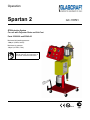
Operation Spartan 2 GC-1355H RTM Injection System For use with Polyester Resin and Gel-Coat Parts 23200-00 and 23240-00 Maximum fluid working pressure: 1300 psi. (9 MPa, 90 bar) Maximum air pressure: 100 psi. (0.7 MPa, 7 bar) Important Safety Instructions Read all warnings and instructions in this manual. Save these instructions. II 2 G Contents Warnings Warnings ............................................................................................................................................................ Important Safety Information............................................................................................................................... Grounding .......................................................................................................................................................... 3 5 6 Set-up Set-up Instructions ............................................................................................................................................. Pressure Relief Instructions ............................................................................................................................... Start-up Instructions ........................................................................................................................................... Shut-down Instructions ....................................................................................................................................... Parts ................................................................................................................................................................... Assembly Drawings ............................................................................................................................................ Sub-Assembly Drawings .................................................................................................................................... 8 9 10 16 17 18 23 Maintenance Maintenance ....................................................................................................................................................... Accesories .......................................................................................................................................................... 33 34 Technical Data Technical Data .................................................................................................................................................. Graco Ohio Standard Warranty................................................................................................... Graco Ohio Information ............................................................................................................... 39 40 40 N/A = Non Applicable 2 GC-1355H 9CTPKPIU The following warnings are for the setup, use, grounding, maintenance, and repair of this equipment. The exclamation point symbol alerts you to a general warning and the hazard symbol refers to procedureVSHFL¿FULVN5HIHUEDFNWRWKHVHZDUQLQJV$GGLWLRQDOSURGXFWVSHFL¿FZDUQLQJVPD\EHIRXQGWKURXJKRXWWKH body of this manual where applicable. • See Important Safety Information - MEKP, Polyester Resins and Gel-Coats and Spraying and Lamination Operations section of this manual. 9#40+0) FIRE AND EXPLOSION HAZARD Flammable fumes, such as solvent and paint fumes, in work area can ignite or explode. To help SUHYHQW¿UHDQGH[SORVLRQ • Use equipment only in well ventilated area. • Eliminate all ignition sources; such as pilot lights, cigarettes, portable electric lamps, and plastic drop cloths (potential static arc). .HHSZRUNDUHDIUHHRIGHEULVLQFOXGLQJVROYHQWUDJVDQGJDVROLQH 'RQRWSOXJRUXQSOXJSRZHUFRUGVRUWXUQSRZHURUOLJKWVZLWFKHVRQRURIIZKHQÀDPPDEOH fumes are present. *URXQGDOOHTXLSPHQWLQWKHZRUNDUHD6HHGrounding instructions. • Use only grounded hoses. +ROGJXQ¿UPO\WRVLGHRIJURXQGHGSDLOZKHQWULJJHULQJLQWRSDLO ,IWKHUHLVVWDWLFVSDUNLQJRU\RXIHHODVKRFNstop operation immediately. Do not use equipment until you identify and correct the problem. .HHSDZRUNLQJ¿UHH[WLQJXLVKHULQWKHZRUNDUHD PERSONAL PROTECTIVE EQUIPMENT You must wear appropriate protective equipment when operating, servicing, or when in the operating area of the equipment to help protect you from serious injury, including eye injury, LQKDODWLRQRIWR[LFIXPHVEXUQVDQGKHDULQJORVV7KLVHTXLSPHQWLQFOXGHVEXWLVQRWOLPLWHGWR • Protective eyewear &ORWKLQJDQGUHVSLUDWRUDVUHFRPPHQGHGE\WKHÀXLGDQGVROYHQWPDQXIDFWXUHU • Gloves • Hearing protection TOXIC FLUID OR FUMES HAZARD 7R[LFÀXLGVRUIXPHVFDQFDXVHVHULRXVLQMXU\RUGHDWKLIVSODVKHGLQWKHH\HVRURQVNLQLQKDOHGRU swallowed. 5HDG06'6¶VWRNQRZWKHVSHFL¿FKD]DUGVRIWKHÀXLGV\RXDUHXVLQJ 6WRUHKD]DUGRXVÀXLGLQDSSURYHGFRQWDLQHUVDQGGLVSRVHRILWDFFRUGLQJWRDSSOLFDEOH guidelines. • Always wear impervious gloves when spraying or cleaning equipment. GC-1355H 3 Warnings 9#40+0) SKIN INJECTION HAZARD +LJKSUHVVXUHÀXLGIURPJXQKRVHOHDNVRUUXSWXUHGFRPSRQHQWVZLOOSLHUFHVNLQ7KLVPD\ORRN OLNHMXVWDFXWEXWLWLVDVHULRXVLQMXU\WKDWFDQUHVXOWLQDPSXWDWLRQGet immediate surgical treatment. • Do not point gun at anyone or at any part of the body. • Do not put your hand over the dispense outlet. 'RQRWVWRSRUGHÀHFWOHDNVZLWK\RXUKDQGERG\JORYHRUUDJ (QJDJHWULJJHUORFNZKHQQRWVSUD\LQJ • Follow Pressure Relief Procedure in this manual, when you stop spraying and before cleaning, FKHFNLQJRUVHUYLFLQJHTXLSPHQW MOVING PARTS HAZARD 0RYLQJSDUWVFDQSLQFKRUDPSXWDWH¿QJHUVDQGRWKHUERG\SDUWV • Keep clear of moving parts. • Do not operate equipment with protective guards or covers removed. 3UHVVXUL]HGHTXLSPHQWFDQVWDUWZLWKRXWZDUQLQJ%HIRUHFKHFNLQJPRYLQJRUVHUYLFLQJ equipment, follow the Pressure Relief Procedure in this manual. Disconnect power or air supply. EQUIPMENT MISUSE HAZARD Misuse can cause death or serious injury. 'RQRWRSHUDWHWKHXQLWZKHQIDWLJXHGRUXQGHUWKHLQÀXHQFHRIGUXJVRUDOFRKRO 'RQRWH[FHHGWKHPD[LPXPZRUNLQJSUHVVXUHRUWHPSHUDWXUHUDWLQJRIWKHORZHVWUDWHGV\VWHP component. See Technical Data in all equipment manuals. 8VHÀXLGVDQGVROYHQWVWKDWDUHFRPSDWLEOHZLWKHTXLSPHQWZHWWHGSDUWV6HHTechnical Data LQDOOHTXLSPHQWPDQXDOV5HDGÀXLGDQGVROYHQWPDQXIDFWXUHU¶VZDUQLQJV)RUFRPSOHWH information about your material, request MSDS forms from distributor or retailer. &KHFNHTXLSPHQWGDLO\5HSDLURUUHSODFHZRUQRUGDPDJHGSDUWVLPPHGLDWHO\ZLWKJHQXLQH manufacturer’s replacement parts only. • Do not alter or modify equipment. • Use equipment only for its intended purpose. Call your distributor for information. 5RXWHKRVHVDQGFDEOHVDZD\IURPWUDI¿FDUHDVVKDUSHGJHVPRYLQJSDUWVDQGKRWVXUIDFHV 'RQRWNLQNRURYHUEHQGKRVHVRUXVHKRVHVWRSXOOHTXLSPHQW .HHSFKLOGUHQDQGDQLPDOVDZD\IURPZRUNDUHD • Comply with all applicable safety regulations. PRESSURIZED ALUMINUM PARTS HAZARD Do not use 1,1,1-trichloroethane, methylene chloride, other halogenated hydrocarbon solvents or ÀXLGV FRQWDLQLQJ VXFK VROYHQWV LQ SUHVVXUL]HG DOXPLQXP HTXLSPHQW 6XFK XVH FDQ FDXVH VHULRXV chemical reaction and equipment rupture, and result in death, serious injury, and property damage. 4 GC-1355H Important Safety Information Methyl Ethyl Ketone Peroxide (MEKP) MEKP is among the more hazardous materials found in commercial channels. Proper handling of the “unstable (reactive)” chemicals presents a GH¿QLWHFKDOOHQJHWRWKHSODVWLFVLQGXVWU\7KH KLJKO\UHDFWLYHSURSHUW\ZKLFKPDNHV0(.3 valuable to the plastics industry in producing the curing reaction of polyester resins and gel-coats also produces the hazards which require great care and caution in its storage, transportation, handling, processing and disposal. :RUNHUVPXVWEHWKRURXJKO\LQIRUPHGRIWKHKD]DUGV that may result from improper handling of MEKP, especially in regards to contamination and heat. They must be thoroughly instructed regarding the SURSHUDFWLRQWREHWDNHQLQWKHVWRUDJHXVHDQG disposal of MEKP and other hazardous materials used in the laminating operation. 0(.3LVÀDPPDEOHDQGSRWHQWLDOO\H[SORVLYH as well as potentially damaging to the eyes and skin. Read material manufacturer’s warnings and PDWHULDO06'6WRNQRZVSHFL¿FKD]DUGVDQG precautions related to MEKP. Contaminated MEKP can become explosive. Prevent contamination of MEKP with other materials, which includes, but is not limited to polyester overspray, polymerization accelerators and promoters, and non-stainless metals. Even small amounts RIFRQWDPLQDWHVFDQPDNH0(.3H[SORVLYH7KLVUHaction may start slowly, and gradually build-up heat, ZKLFKFDQDFFHOHUDWHXQWLO¿UHRUDQH[SORVLRQUHVXOW 7KLVSURFHVVFDQWDNHIURPVHFRQGVWRGD\V Heat applied to MEKP, or heat build-up from contamination reactions can cause it to reach what is called its Self-Accelerating Decompisition TemperaWXUH6$'7ZKLFKFDQFDXVH¿UHRUH[SORVLRQ Spills should be promptly removed, so no residues remain. Spillage can heat up to the point of selfignition. Dispose in accordance with manufacture’s recommendation. Store MEKP in a cool, dry and well-ventilated area in the original containers away from direct sunlight and away from other chemicals. It is strongly recommended that the storage temperature remain below 86° F (30° C). Heat will increase the potential for explosive decomposition. Refer to NFPA 432. .HHS0(.3DZD\IURPKHDWVSDUNVDQGRSHQ ÀDPHV GC-1355H Current catalysts are premixed and do not require any diluents. GlasCraft strongly recommends that diluents not be used. Diluants add to the possibility of contaminates entering the catalyst system. Never dilute MEKP with acetone or any solvent since this can proGXFH DQ H[WUHPHO\ VKRFNVHQVLWLYH FRPSRXQG ZKLFK can explode. Use only original equipment or equivalent parts IURP *ODV&UDIW LQ WKH FDWDO\VW V\VWHP LH KRVHV ¿Wtings, etc.) because a hazardous chemical reaction may result between substituted parts and MEKP. To prevent contact with MEKP, appropriate personal protective equipment, including chemically impermeable gloves, boots, aprons and goggles are required IRUHYHU\RQHLQWKHZRUNDUHD Polyester Resins and Gel-Coats Spraying materials containing polyester resin and gel-coats creates potentially harmful mist, vapors and atomized particulates. Prevent inhalation by providing VXI¿FLHQWYHQWLODWLRQDQGWKHXVHRIUHVSLUDWRUVLQWKH ZRUNDUHD Read the material manufacturer’s warnings and maWHULDO06'6WRNQRZVSHFL¿FKD]DUGVDQGSUHFDXWLRQV related to polyester resins and gel-coats. To prevent contact with polyester resins and gelcoats, appropriate personal protective equipment, including chemically impermeable gloves, boots, aprons and goggles are required for everyone in the ZRUNDUHD Spraying and Lamination Operations Remove all accumulations of overspray, FRP sandings, etc. from the building as they occur. If this waste LVDOORZHGWREXLOGXSVSLOODJHRIFDWDO\VWLVPRUHOLNHO\ WRVWDUWD¿UH If cleaning solvents are required, read material PDQXIDFWXUH¶VZDUQLQJVDQGPDWHULDO06'6WRNQRZ VSHFL¿FKD]DUGVDQGSUHFDXWLRQV*ODV&UDIWUHFRPPHQGVWKDWFOHDQXSVROYHQWVEHQRQÀDPPDEOH GlasCraft recommends that you consult OSHA Sections 1910.94, 1910.106, 1910.107 and NFPA No. 33, Chapter 16,17, and NFPA No. 91 for further guidance. 5 Grounding This equipment needs to be grounded. Ground the dispense gun through connection to a *ODV&UDIWDSSURYHGJURXQGHGÀXLGVXSSO\KRVH &KHFN\RXUORFDOHOHFWULFDOFRGHDQGUHODWHGPDQXDOV for detailed grounding instructions of all equipment in WKHZRUNDUHD A grounding wire and clamp are provided, assembly p/n 17440-00 with all FRP equipment. 6 GC-1355H Set-Up 7KH6SDUWDQOOFRPHVFRPSOHWHDQG¿WWHGZLWKDOO UHVLQKRVHVFDWDO\VWERWWOHDQG¿OWHUV7KHLQMHFWLRQ head is fully connected to the machine circuit and tested and secured against leaks prior to dispatch. The following instructions are to be used as a guide for consistent and continual operation. Any deviation from the “standard operation”, usually requires more maintenance to the equipment and material formulation to assure consistent results. For H[DPSOHWKHXVHRI¿OOHUVLQUHVLQV Slave Pump 5HIHUWRVSHFL¿FXVHUPDQXDOVLIDYDLODEOHIRU detailed component start-up and shut-down instructions. 1. Select a clean, dry air supply. It is very important to have a clean air supply. 2. Attach a 3/8” or larger air hose to the Air Inlet on the \HOORZDLUORFNRXWYDOYH4XLFNGLVFRQQHFW¿WWLQJV should not be used because they can severely limit DLUÀRZ :KHQHYHUÀDPPDEOHRUFRPEXVWLEOHOLTXLGVDUHWUDQVfered from one container to another, both containers shall be effectively bonded and grounded to dissipate static electricity. For further information see..... NFPA 77,Recommended Practice on Static Electricity. 5. Remove the pump inlet saftey cap and drain the testing oil into an open container. 6. $WWDFKFDVWHUVZLWKSURYLGHGORFNZDVKHUZDVKHUDQG QXW$WWDFKVROYHQWWDQNVXSSRUWURGRQEDFNOHIWFDVWHU Before turning on main air: D&KHFNDOO¿WWLQJVPDNLQJFHUWDLQWKH\DUHVHFXUHO\ tightened. E0DNHVXUHDOOUHJXODWRUVDUHVHWWR]HURWXUQDOO WKHZD\WRWKHOHIW This should be done before air or material of any kind is introduced into the system. 3. Attach Grounding Clamp Assembly, P/N 17440-00, to System. Use a convenient Nut and Bolt to secure Lug, P/N 13193-00, to slave pump. 7. $WWDFKVROYHQWWDQNWRVROYHQWWDQNVXSSRUWURGZLWK provided rubber strap. 4. Securely attach Clamp, P/N 7749-00 to permanently grounded rod or pipe. GC-1355H 7 Set-Up 8. Attach the FDWDO\VWMXJEUDFNHWWR the mast. 9. Attach the green material hose WRWKHSLFNXSWXEHDQGLQVHUWWKH WXEHLQWRDEXFNHWRIFOHDQVROYHQW Recirculation hose from the gun. SOLVENT CONTAINER 10. Attach the green material hose to the material pump. SOLVENT/WASTE CONTAINER 11. Insert the end of the recirculation hose into a waste container. 8 GC-1355H Pressure Relief Procedure 7RUHOLHYHÀXLGDQGDLUSUHVVXUHV 1. Push down Yellow slide valve, P/N 21402-00 to bleed off air to system. 2. Open P/N 21228-00 on catalyst pump to recirculation position. 3. Open P/N 21192-00 on bottom of material pump. GC-1355H 9 Start-Up 12. 0DNHVXUHVROYHQWUHJXODWRULVGLDOHGWR]HUR 7XUQNQREIXOO\FRXQWHUFORFNZLVH 17. Replace yellow guard using a 5/32” hex balldriver. 13. &DUHIXOO\UHOLHYHDQ\SUHVVXUHLQWKHVROYHQWWDQNE\ slowly pulling the relief valve. 14. $IWHUDOOWKHSUHVVXUHLVUHOHDVHGIURPWKHWDQNRSHQ WKHOLGDQG¿OOWKHWDQNZLWKDVXLWLEOHFOHDQÀXVKLQJ solvent and close the lid securely. 18. %HIRUHRSHUDWLQJWKHPDWHULDOSXPSÀXVKWKRURXJKO\ ZLWKDFOHDQVXLWDEOHVROYHQWWRUHPRYHWHVWÀXLG 15. Remove yellow guard using a 5/32” hex balldriver. *ODV&UDIWXVHVWHVWÀXLGWKDWPD\QRWEHFRPSDWLEOH ZLWKVRPHUHVLQV,WLVUHFRPPHQGHGWKDWWKHWHVWÀXLG EHÀXVKHGIURPWKHPDWHULDOSXPSÀXLGVHFWLRQ 0DNHVXUHKRVH¿WWLQJVRQWKHSLFNXSKRVHVDUHWLJKW 19. 6DIHO\¿OOWKH&DWDO\VW6XSSO\%RWWOH31/3$ (maximum two gallons) with preferred MEKP catalyst, to a minimum level of at least two inches above the Catalyst Bottle Outlet Fitting. 16. Fill material pump lube cup with proper pump lube. 10 Remove Catalyst Bottle, P/N 20941-00 from Catalyst %RWWOH EUDFNHW 31 /3$ IRU ¿OOLQJ %RWWOH VKRXOG EHSODFHGDWRUEHORZORZHVWOHYHOIRUVDIH¿OOLQJ1HYHU ¿OO&DWDO\VWERWWOHZKLOHPRXQWHGLQEUDFNHWDVSHUVRQDO LQMXU\IURPFDWDO\VWVSLOODJHFRXOGUHVXOW GC-1355H Start-Up 7KH6SDUWDQOOFRPHVFRPSOHWHDQG¿WWHGZLWKDOO UHVLQKRVHVFDWDO\VWERWWOHDQG¿OWHUV7KHLQMHFWLRQ head is fully connected to the machine circuit and tested and secured against leaks prior to dispatch. 2. Place injection nozzle over a proper waste container. 7XUQZD\YDOYHRQWRSRIWKHVROYHQWWDQNVRWKH arrow is pointing up for air purge, for solvent turn the valve so the arrow is pointing down. Repeat air purge to blow solvent through the gun head. The following instructions are to be used as a guide for consistent and continual operation. Any deviation from the “standard operation”, usually requires more maintenance to the equipment and material formulation to assure consistent results. For H[DPSOHWKHXVHRI¿OOHUVLQUHVLQV 5HIHUWRVSHFL¿FXVHUPDQXDOVLIDYDLODEOHIRU detailed component start-up and shut-down instructions. 6ROYHQW Before initial operation of any internal mix system, PDNHFHUWDLQWKHVROYHQWÀXVKVHWXSLVIXOO\ operational. 3-way valve 1. 7XUQVROYHQWUHJXODWRUFORFNZLVHWRDSSUR[LPDWHO\ 65 psi. 3. Exhaust air through the gun head until traces of solvent have been dissipated. Since the system is an internal mix system, the mixer UHTXLUHVÀXVKLQJZLWKDLUVROYHQWDLUDIWHUHDFKGLVSHQVHRU before the mixed material starts to gel. GC-1355H 11 Start-Up 4. Switch machine recirculation to “ON”. Resin 1. Detach the catalyst slave pump from the material pump. 3XOODQGURWDWHNQREWRGLVHQJDJHWKHFDWDO\VWGULYHDUP ĸ Knob RECIRCULATION ON OFF 5. 7XUQWKHPDWHULDOLQMHFWLRQUHJXODWRUVORZO\FORFNZLVH until gauge indicates 10 PSI or until pump cycles slowly. ĺ 2. Turn main valve on the gun head to the recirculation position. ĸ 8. Pump should cycle clean solvent through the system and out the recirculation hose. 9. End recirculation when solvent appears reasonably clean. “OFF” 3.7XUQWKHPDWHULDODLUUHJXODWRUIXOO\FRXQWHUFORFNZLVH ĺ ĸ RECIRCULATION ON OFF 10. 5HPRYHPDWHULDOSXPSSLFNXSWXEHIURPVROYHQW container and dry thoroughly. 12 GC-1355H Start-Up 11. Switch machine recirculation to “ON”. ĸ Catalyst 1. Turn Catalyst Valve on the dispense gun to recirculation RECIRCULATION ON OFF position (arrow on valve should point away from gun EORFN 12. When solvent has stopped exiting the recirculation hose, end recirculation. (OFF) ĺ ĺ RECIRCULATION ON OFF 13. 3ODFHPDWHULDOSXPSSLFNXSWXEHLQGHVLUHGFRQ WDLQHURIPDWHULDOZKLOHNHHSLQJUHFLUFXODWLRQUHWXUQ hose in a waste container. Make sure all the air is purged out of the catalyst pump on new start up. 14. Turn machine to recirculation. (ON) ĸ RECIRCULATION ON OFF 2a. Pull and rotate Pivot NQREWRGLVHQJDJHWKHFDWDO\VW drive arm. 15. Let material pump cycle slowly until a steady stream of clean material is seen exiting the recirculation hose. 16. Switch machine recirculation to “OFF”. ĺ RECIRCULATION ON OFF E Turn the slave pump yellow ball valve to the open position. c. Hand prime the pump until a steady stream of catDO\VWÀRZVEDFNWRWKHERWWOH d. Close the ball valve. Hand VWURNHWKHSXPSXQWLOLWGHYHO opes 100-200 PSI. 17. Secure recirculation hose in the material supply container. 3. Set the slave pump to 3.5 percent. Dispose of resin in the waste container in a proper manner. GC-1355H 13 Start-Up 3. 7XUQDLUPRWRUSUHVVXUHUHJXODWRUVORZO\FORFNZLVH until pump cycles slowly. It is usually a general practice when starting up the system to let the system recirculate with the Catalyst Slave Pump set at 3.5%. This ensures good catalyst volume movement through the system to remove air in the catalyst system. ĺ 4. 5HHQJDJHWKHFDWDO\VWSLYRWNQRE Notice Make sure that the knob engages inside the catalyst drive arm slot. Failure to do so will cause damage to the catalyst drive arm. Recirculation Mode (Start-Up) The Recirculation Mode should be used in initial start-up or when air bubbles are observed coming through the ends of the Recirculation Hoses. Injection Instructions 1. Both Catalyst Valve and Material Valve on the Dispense Gun should be in the Recirculation position. 1. Switch machine to injection. (set recirculation to off) ĸ ĺ RECIRCULATION ON OFF 2. Turn valves on gun head to injection. ĺ ĺ 2. Switch machine recirculation to “ON”. Ĺ ĸ RECIRCULATION ON OFF 14 :KHQPDNLQJWHVWPDWHULDOGLVSHQVHVRUGXULQJÀXVKing operation, make certain that dispensed material and/or solvent is contained in a suitable container and that this material and/or solvent is disposed of properly. GC-1355H Start-Up 7. Flush gun head thoroughly. Turn 3-way valve on top RIWKHVROYHQWWDQNVRWKHDUURZLVSRLQWLQJXSIRUDLU purge, for solvent turn the valve so the arrow is pointing down. 3-way valve GC-1355H 15 Shut-Down Shut Down Procedure 5. Material pump should now be cycled so that shaft is left in down position during shut-down period. The purpose of the shut down procedure is to verify that all critical parts of the system, i.e., the mixing area, KDYHEHHQFKHFNHGDQGFOHDQHGWRDVVXUHWURXEOHIUHH start-up the next time the system is to be operated. 1. 7XUQERWKEDOOYDOYHVRQJXQKHDGWR³2))´Û Ĺ 6. ,I\RXDUHXVLQJ¿OOHUVPL[HGLQWRWKHUHVLQUHPHP EHURQSHULRGVRIVKXWGRZQWKH¿OOHUVFDQVHWWOHWR WKHERWWRPRIWKHSXPSDQGSLSHZRUNV ,IXVLQJD¿OOHGUHVLQLWLVVXJJHVWHGWKDWWKHPDWHULDO SXPSDQGKRVHVEHÀXVKHGZLWKD³QHDW´UHVLQDQG WKDWWKHQHDWUHVLQLVÀRZLQJWKURXJKWKHV\VWHPDQG exiting the material recirculation hose thoroughly before shut down procedures are completed. 7. 6KXWGRZQPDLQDLUVXSSO\E\FORVLQJ\HOORZORFN out valve. Ĺ 2. Flush gun head with solvent and air purge thoroughly. 3. Material pump should be stopped with pump shaft in up position and shaft should be cleaned of any contaminants. 8. 6ORZO\EOHHGWKHDLUSUHVVXUHIURPWKHWDQNE\OLIWLQJ the ring on the relief valve. Notice 4. Material pump lube cup should be cleaned of old OXEHDQGUH¿OOHGZLWKQHZSXPSOXEH 16 Failure to cycle Pump Shaft to DOWN position may result in contaminants to dry or harden on shaft. When pump is next operated, severe damage may be done to upper pump seals. GC-1355H Parts Spartan II System Standard Equipment Part 1XPEHU Description 20864-06 0$7(5,$/3803$66(0%/<5$7,2 SSP-160-01 SUPER CATALYST SLAVE PUMP ASSEMBLY 21661-00 AIR LOGIC ASSEMBLY 20941-00 CATALYST BOTTLE ASSEMBLY LPA-169 CATALYST BOTTLE BRACKET ASSEMBLY 18291-01 / 20569-01 BASE & MAST GC-1355H 21654-00 SOLVENT TANK ASSEMBLY GAM-268-01 MATERIAL PUMP PICK-UP KIT 21694-25 MATERIAL HOSE ASSEMBLY, 25 FT. 20195-30 MATERIAL RECIRCULATION HOSE 17440-00 GROUNDING CLAMP ASSEMBLY 20190-30 CATALYST HOSE 30 FT. 20945-00 CATALYST RECIRCULATION HOSE 21054-01 SOLVENT HOSE 38 FT. 21668-01 GUN ASSEMBLY 23220-00 CONTROL BOX ASSEMBLY GC-1355 MANUAL 17 18 ** For a detailed view, see GC-1303 * For a detailed view, see GC-1337 * ** $VVHPEO\'UDZLQJV 8QLW$VVHPEO\ REVISION F GC-1355H $VVHPEO\'UDZLQJV 8QLW$VVHPEO\ REVISION F GC-1355H 19 $VVHPEO\'UDZLQJV 8QLW$VVHPEO\ REVISION F 20 GC-1355H $VVHPEO\'UDZLQJV * * Part numbers 20732-01 and 21054-01 go inside of 9704-09. * 23200-00 Hose Diagram REVISION F GC-1355H 21 $VVHPEO\'UDZLQJV 8QLW$VVHPEO\ Part 1XPEHU Description Part 1XPEHU Description CONTROL BOX CP-126 U-BOLT 23220-00 FM-494 EXPANDABLE SLEEVING 23231-00 SPARTAN II DECAL G-403 RUBBER TARP STRAP 23241-00 SPARTAN II DECAL GAM-268-01 PICK-UP TUBE 3923-02 SPIRAL WRAP LPA-169 BOTTLE SUPPORT 7486-04 WASHER SSP-160-01 PUMP MOUNTING ASSY. 7486-05 WASHER SSP-172 SURROUND GUARD 7486-07 WASHER SSP-173 LEFT PUMP GUARD 7486-10 WASHER SSP-174 GUARD ANGLE BRACKET 7486-13 WASHER SSP-176 GUARD WINDOW 7733-12 HEX NUT SSP-177 RIGHT REAR PUMP GUARD 7733-14 HEX NUT SSP-178 RIGHT FRONT PUMP GUARD 7733-42 HEX NUT 13424-01 CABLE TIE 7734-06 LOCK WASHER 17440-00 GROUNDING CLAMP 7734-07 LOCK WASHER 18245-02 HEAT SHRINK TUBING 7734-10 LOCK WASHER 18291-01 FLOOR MOUNT MAST 7734-12 LOCK WASHER 19845-00 LITERATURE KIT 7957-32C SCREW 19882-00 SUPPORT MAST CAP 7957-32F SCREW 19889-00 MOUNTING ADAPTER 7958-56C SCREW 19891-00 PIPE CLAMP 8155-160C SCREW 19892-00 COVER PLATE 9704-11 TUBING 20188-16C SCREW 9704-83 TUBING 20190-30 CATALYST HOSE 9955-24C SCREW 20195-30 MATERIAL HOSE 20368-00 SWIVEL CASTER 20569-01 SPARTAN SUPPORT MAST 20731-04 POLYETHYLENE TUBING 20732-01 POLYETHYLENE TUBING 20732-06 POLYETHYLENE TUBING 20864-06 SPARTAN II PUMP ASSY. 20941-00 CATALYST JUG 20945-00 CATALYST RECIRCULATION ASSY. 21054-01 NYLON TUBING 21203-12 POLYURETHANE TUBING 21654-00 SOLVENT TANK 21658-00 MOUNTING BRACKET 21663-00 GUN MOUNTING BLOCK 21668-01 SPARTAN II GUN ASSY 21670-00 SUPPORT TANK 21674-00 GUIDE HOSE ASSY. 21694-25 MATERIAL HOSE REVISION F 22 GC-1355H 6XE$VVHPEO\'UDZLQJV &RQWURO%R[$VVHPEO\ REVISION H GC-1355H 23 6XE$VVHPEO\'UDZLQJV &RQWURO%R[$VVHPEO\ REVISION H 24 GC-1355H 6XE$VVHPEO\'UDZLQJV &RQWURO%R[$VVHPEO\ REVISION H GC-1355H 25 6XE$VVHPEO\'UDZLQJV &RQWURO%R[$VVHPEO\ 26 Part 1XPEHU Description Part 1XPEHU ISD-141-3 MINI REGULATOR 23201-02 Description PANEL NUT MPB-208 AIR FILTER 23202-00 WALL MOUNTED BRACKET 15544-02 BULKHEAD FITTING 23203-00 REGULATOR 18199-02 AIR REGULATOR 23204-00 PANEL MOUNT GAUGE 19916-00 PUSH SWITCH 23205-00 REGULATOR 20655-01 ELBOW FITTING 23206-00 SPARTAN START BUTTON 20655-04 ELBOW FITTING 23207-00 SPARTAN E-STOP BUTTON 20711-00 AIR VALVE 23208-00 SELECTOR SWITCH 20712-00 RELAY SUBPLATE 23209-00 ADAPTER VALVE 20735-01 ELBOW FITTING 23210-01 TUBE REDUCER 20735-03 ELBOW FITTING 23210-02 TUBE REDUCER 20735-04 ELBOW FITTING 23212-00 SPARTAN II CONTROL BOX 20735-05 ELBOW FITTING 23213-00 SPOOL VALVE 20750-00 MALE RUN SWIVEL TEE 23214-00 FITTING 20754-00 ELBOW FITTING 23214-01 FITTING 20796-00 FITTING 23214-02 FITTING 20796-02 FITTING 23215-00 AIR MANIFOLD 20796-04 FITTING 23226-00 MOTOR PRESSURE DECAL 20878-00 MINIATURE VALVE 23227-00 START DECAL 20878-01 MINIATURE VALVE 23228-00 ACCU-PRESSURE ON-OFF DECAL 20878-02 MINIATURE VALVE 23229-00 ACCU-PRESSURE DECAL 20895-00 2 COND. CABLE 23230-00 REMOTE INJECTION DECAL 21203-02 POLYURETHANE TUBING 23232-00 PRESSURE SWITCH 21203-04 POLYURETHANE TUBING 23233-00 NEEDLE VALVE 21203-12 POLYURETHANE TUBING 23235-00 STROKE COUNTER DECAL 21203-13 POLYURETHANE TUBING 23236-00 STROKE COUNTER DECAL 21203-14 POLYURETHANE TUBING 23237-00 FITTING 21402-00 VALVE 23237-01 FITTING 21454-00 MOUNTING BRACKET 23238-00 OPEN/CLOSED DECAL 21470-00 COUNTER 4342-04 ELBOW FITTING 21489-48C SCREW 5754-05 TERMINAL LUG 21604-01 PLASTIC TUBE PLUG 7315-05 RUBBER GROMMET 21604-02 PLASTIC TUBE PLUG 7315-06 RUBBER GROMMET 21678-00 RECIRCULATION DECAL 7733-04 HEX NUT 22104-00 EMERGENCY STOP DECAL 7733-07 HEX NUT 22212-01 BULKHEAD FITTING 7733-12 HEX NUT 22212-02 BULKHEAD FITTING 7734-02 LOCK WASHER 22218-00 FITTING 7734-04 LOCK WASHER LOCK WASHER 22224-00 TEE FITTING 7734-06 22230-00 REGULATOR FILTER 7959-96C 22238-01 POPPET VALVE 8115-03 FITTING 22363-01 FITTING 8212-48F SCREW 22624-00 SPOOL VALVE 9672-16 FITTING 23201-01 PANEL NUT 9943-16F SCREW SCREW GC-1355H 6XE$VVHPEO\'UDZLQJV *XQ$VVHPEO\ 23547-01 &KHFN9DOYH$VVHPEO\ Accu-Pressure Valve REVISION E GC-1355H 27 6XE$VVHPEO\'UDZLQJV *XQ$VVHPEO\ Part 1XPEHU Description Qty. Part 1XPEHU Description Qty. RM-856-04 ELBOW FITTING 1 7597-04 SWIVEL FITTING 1 13076-32 O-RING 1 7734-04 LOCK WASHER 2 13867-61 O-RING 1 7966-17 FITTING 1 13867-62 O-RING 1 8114-03 ELBOW FITTING 1 13867-63 O-RING 1 8212-16C SCREW 2 15902-00 FITTING 1 8462-17 FITTING 1 19881-00 FITTING 1 8560-03 FITTING 1 20306-00 ELBOW FITTING 1 8560-22 FITTING 1 20735-04 ELBOW FITTING 1 9944-48C SCREW 4 20796-02 FITTING 1 20796-03 FITTING 1 20810-00 BALL VALVE 1 20878-00 VALVE 1 20879-00 PUSH BUTTON 1 21044-02 O-RING 1 21454-00 MOUNTING BRACKET 1 21465-32C STUD 2 21535-00 CHECK VALVE 1 21656-00 GUN BLOCK 2 21662-00 INJECTION WAND 1 21664-00 CHECK VALVE 1 21665-00 GUN HANDLE 2 21667-00 BALL VALVE 1 21675-00 CHECK VALVE 2 21676-00 CRUSH WASHER 2 22904-00 CHECK VALVE STEM 1 22906-00 CRUSH WASHER 1 22908-00 NUT 1 22909-00 CHECK VALVE BODY 1 23216-00 MPS BLOCK 1 23217-00 PRESSURE SENSOR PISTON 1 23218-00 BOTTOM PLATE 1 23219-00 TOP PLATE 1 23221-00 GASKET 1 23223-00 INJECTION PORT 1 23524-01 SPRING 1 23540-00 CHECK VALVE BODY 1 REVISION E 28 GC-1355H 6XE$VVHPEO\'UDZLQJV &KHFN9DOYH$VVHPEO\ 22909-00 Not included with 23547-01 assembly USE LOW STRENGTH THREAD LOCKER ON THREADS. 21664-00 21675-00 6ROYHQW$LU3XUJH5HVLQ &KHFN9DOYH$VVHPEO\&KHFN9DOYH$VVHPEO\ GC-1355H 29 6XE$VVHPEO\'UDZLQJV *$00DWHULDO3LFN8S.LW Part 1XPEHU Description Qty. 20394-00 PICK-UP TUBE 1 20395-00 ELBOW FITTING 1 20397-01 MESH FILTER 1 20398-02 MATERIAL HOSE 1 Filter Options Part 1XPEHU Description 20397-02 100 MESH 20397-03 50 MESH REVISION D 30 GC-1355H 6XE$VVHPEO\'UDZLQJV 20941-00 Catalyst Bottle Assembly Part 1XPEHU Description Qty. LPA-172 BOTTLE SUPPLY FILTER 1 20390-00 FITTING 1 20934-00 JUG CAP 1 20939-00 MALE CONNECTOR 2 20940-00 SUPPLY BOTTLE 1 21039-00 FITTING 1 21040-00 ELBOW FITTING 1 21045-01 HEX NUT 1 9704-11 TUBING 5 REVISION G GC-1355H 31 6XE$VVHPEO\'UDZLQJV 6ROYHQW7DQN$VVHPEO\ Part 1XPEHU Description Qty. ISD-141-3 MINI REGULATOR 1 ISD-142 SOLVENT POT GAUGE 1 1 11021-23 PIPE PLUG 20263-00 VALVE 1 20324-00 SOLVENT TANK 1 20365-00 VALVE 1 20655-02 ELBOW FITTING 1 20720-00 VALVE 1 20798-02 FITTING 1 21669-00 CHECK VALVE 1 4342-01 ELBOW FITTING 1 7596-01 FITTING 1 7892-01 FITTING 1 8115-01 FITTING 1 REVISION D 32 GC-1355H Maintenance 7URXEOHVKRRWLQJ Before performing any maintenance on this system, follow pressure relief procedures on page 9. Notice Due to the different O-Ring materials and lubricants used in the Dispense Guns never submerge or soak any dispense gun in any type of solvent! Submerging or soaking any Dispense Gun will immediately void the Gun warranty. Maintenance It is recommended that the following service be SHUIRUPHGRQDZHHNO\EDVLV 1. ,QVSHFWDQGOXEULFDWH&DWDO\VW6ODYH3XPS/LQNDJH (See Catalyst Slave Pump User Manual.) 2. Inspect Pump Shafts on Material and Catalyst 3XPSVPDNLQJFHUWDLQWKH\DUHFOHDQDQGIUHHRI foreign material. Clean and lubricate as required. For long term storage of your injection system, it is recommended that the following procedures be IROORZHG 1. Place dry nitrogen in the material drums and secure drum. 2. 0DNHFHUWDLQDOODLUDQGPDWHULDOYDOYHVDUHLQWKHLU “OFF” position. GlasCraft recommends that you contact your gelcoat and/or resin supplier concerning material pot-life during extended periods of shut-down. The decision as to whether or not to leave material in your system should be based on information from your material suppliers as well as GlasCraft. Consult your local authorized GlasCraft distributor for more information concerning system storage. GC-1355H Before altering catalyst percentage by moving the catalyst pump to a new desired location on the ratio arm ALWAYS ensure that the catalyst recirculation valve is turned to the recirculation position, and the air pressure is removed from the system. It is absolutely essential that both streams of material are pumped to the head without air or gas entrapped. For example, if air is drawn into the resin stream through the resin pump inlet system, i.e., via bad connection or ¿OWHUHQGFRPLQJRXWRIUHVLQVXUIDFHWKHQWKLVDLULI not purged out of the machine by recirculating on bypass will naturally go to the head through the mixer and into the RTM mold. This fault condition will manifest itself in the molded part having very small bubbles; DOPRVWLQDIURWKOLNHVWDWHRQWKHXSSHUVLGHRIWKH molded part once the mold is opened. The reason for these bubbles being so small is due to the fact that air coming through the mixer with the resin is mixed and IURWKHGEHIRUH¿QDOO\HQWHULQJWKHPROG Air or gas in the catalyst stream, leads to a different type of fault in the molded part. This condition will be manifest by observing when opening the mold after injection and supposed cure, that there are wet patches of uncured or semi-gelled resin in the molded part. The FDXVHVDWWULEXWHGWRWKLVDUH 1. Air is drawn in by the catalyst pump through a bad connection on the inlet stream from the catalyst container or pump inlet connection. 2. Catalyst contamination in the pump system causing oxidation resulting in peroxide gas bubbles being generated within the supposedly hydraulic sealed system of the catalyst. 3. The catalyst pump has faulty seals or is contaminated with particles. To ensure that the catalyst system is totally hydraulically tight, it is expedient after a period of shut-down that the procedures in the instructions for commissioning the catalyst stream should be repeated. 33 Accessories 23240-00 Spartan II Auto (DELUXE) REVISION D 34 GC-1355H Accessories 23225-00 Spartan II Modules REVISION D GC-1355H 35 Accessories 23225-00 Spartan II Modules REVISION D 36 GC-1355H Accessories 23225-00 Spartan II Modules REVISION D GC-1355H 37 Accessories 23225-00 Spartan II Modules Part 1XPEHU Description Qty. Part 1XPEHU 10080-03 FITTING 1 11021-22 PIPE PLUG 2 13381-12F SCREW 13424-01 CABLE TIE 20735-01 ELBOW FITTING Description Qty. 22232-00 SPOOL VALVE 1 22234-00 INLINE VOLUME CHAMBER 2 14 22235-00 DELAY VALVE 2 3 22236-00 VALVE 1 2 22238-02 POPPET VALVE 1 20796-01 FITTING 3 22239-00 FITTING 1 20796-02 FITTING 24 22240-00 VALVE PLATE 3 20878-00 MINIATURE VALVE 3 22241-01 VALVE MOUNTING BRACKET 2 20879-00 PUSH BUTTON 1 22242-00 PRESSURE INDICATOR 1 21203-01 POLYURETHANE TUBING AN 22244-05F 21203-04 POLYURETHANE TUBING 9 22247-00 GEL TIMER DECAL SCREW 1 8 21203-05 POLYURETHANE TUBING 12 22248-00 ADJUSTMENT DECAL 1 21203-10 POLYURETHANE TUBING 5 22249-00 AIR PURGE DECAL 1 1 21203-11 POLYURETHANE TUBING 7 22251-00 SOLVENT FLUSH DECAL 21203-12 POLYURETHANE TUBING 12 22252-00 SOLVENT ADJUSTMENT DECAL 1 21203-13 POLYURETHANE TUBING 3 22263-00 ADJUSTABLE ”L” FITTING 14 21203-15 POLYURETHANE TUBING 3 22267-00 METROPLITAN WHISTLE 1 21489-48C SCREW 6 23199-00 SIGNAL DELAY 1 21660-00 VALVE 1 23210-01 TUBE REDUCER 2 22205-00 FITTING 7 23210-02 TUBE REDUCER 4 22207-00 FITTING 3 23211-00 HEX STANDOFF 4 22211-00 SPOOL VALVE 2 23215-00 AIR MANIFOLD 1 22212-01 BULKHEAD FITTING 1 23224-00 CONTROL BOX 1 22213-01 RED PUSH BUTTON 1 7315-06 RUBBER GROMMET 1 22213-02 BLACK PUSH BUTTON 1 7486-03 WASHER 14 22213-03 BLACK PUSH BUTTON 1 7486-13 WASHER 8 22214-00 FITTING 4 7733-04 HEX NUT 6 22216-00 SHUTTLE VALVE 3 7733-12 HEX NUT 4 22217-00 PILOT ACTUATOR 2 7734-02 LOCK WASHER 6 22218-00 FITTING 24 7734-06 WASHER,LOCK,SPRING,1/4 4 22219-00 PREDETERMINING COUNTER 1 9944-24C SCREW,SHDC,AS,.250-20X 4 22222-00 DECAL,INJ EMERGENCY,AC 1 22224-00 FTG,TEE,TUBE,PUSH-IN,5 1 AN = AS NEEDED REVISION D 38 GC-1355H Technical Data Category GC-1355H Data 0D[LPXP)OXLG:RUNLQJ3UHVVXUH 1300 psi (9 MPa, 90 bar) Maximum Air Inlet Pressure 100 psi (0.7 MPa, 7 bar) Typical Flow Rate of Pattern Guns Refer to gun manual Maximum Fluid Temperature 100° F (38° C) B Component (Resin) Inlet Size 1 5/16-12 UN-2A Male Sound Pressure 84.83 dB(A) Sound Power, measured per ISO 9614-2 87.04 dB(A) Dimensions 35 L X 35 W X 59 H ( 889 X 889 X 1498.6 mm) Weight /EVNJ Wetted Parts Catalyst- Chemically coated aluminum, stainless steel, chemically resistant o-rings Resin- Carbon steel, carbide, chemically resistant orings. 39 Graco Ohio Standard Warranty Graco warrants all equipment referenced in this document which is manufactured by Graco and bearing its name to be free from GHIHFWVLQPDWHULDODQGZRUNPDQVKLSRQWKHGDWHRIVDOHWRWKHRULJLQDOSXUFKDVHUIRUXVH:LWKWKHH[FHSWLRQRIDQ\VSHFLDO extended, or limited warranty published by Graco, Graco will, for a period of twelve months from the date of sale, repair or replace any part of the equipment determined by Graco to be defective. This warranty applies only when the equipment is installed, operated and maintained in accordance with Graco’s written recommendations. This warranty does not cover, and Graco shall not be liable for general wear and tear, or any malfunction, damage or wear caused by faulty installation, misapplication, abrasion, corrosion, inadequate or improper maintenance, negligence, accident, tampering, or substitution of non-Graco component parts. Nor shall Graco be liable for malfunction, damage or wear caused by the incompatibility of Graco equipment with structures, accessories, equipment or materials not supplied by Graco, or the improper design, manufacture, installation, operation or maintenance of structures, accessories, equipment or materials not supplied by Graco. This warranty is conditioned upon the prepaid return of the equipment claimed to be defective to an authorized Graco distributor IRUYHUL¿FDWLRQRIWKHFODLPHGGHIHFW,IWKHFODLPHGGHIHFWLVYHUL¿HG*UDFRZLOOUHSDLURUUHSODFHIUHHRIFKDUJHDQ\GHIHFWLYHSDUWV The equipment will be returned to the original purchaser transportation prepaid. If inspection of the equipment does not disclose DQ\GHIHFWLQPDWHULDORUZRUNPDQVKLSUHSDLUVZLOOEHPDGHDWDUHDVRQDEOHFKDUJHZKLFKFKDUJHVPD\LQFOXGHWKHFRVWVRI parts, labor, and transportation. THIS WARRANTY IS EXCLUSIVE, AND IS IN LIEU OF ANY OTHER WARRANTIES, EXPRESS OR IMPLIED, INCLUDING BUT NOT LIMITED TO WARRANTY OF MERCHANTABILITY OR WARRANTY OF FITNESS FOR A PARTICULAR PURPOSE. Graco’s sole obligation and buyer’s sole remedy for any breach of warranty shall be as set forth above. The buyer agrees that no other remedy LQFOXGLQJEXWQRWOLPLWHGWRLQFLGHQWDORUFRQVHTXHQWLDOGDPDJHVIRUORVWSUR¿WVORVWVDOHVLQMXU\WRSHUVRQRUSURSHUW\RUDQ\RWKHULQFLGHQWDO or consequential loss) shall be available. Any action for breach of warranty must be brought within two (2) years of the date of sale. GRACO MAKES NO WARRANTY, AND DISCLAIMS ALL IMPLIED WARRANTIES OF MERCHANTABILITY AND FITNESS FOR A PARTICULAR PURPOSE, IN CONNECTION WITH ACCESSORIES, EQUIPMENT, MATERIALS OR COMPONENTS SOLD BUT NOT MANUFACTURED BY GRACO. These items sold, but not manufactured by Graco (such as electric motors, switches, hose, etc.), are subject to the warranty, if any, of WKHLUPDQXIDFWXUHU*UDFRZLOOSURYLGHSXUFKDVHUZLWKUHDVRQDEOHDVVLVWDQFHLQPDNLQJDQ\FODLPIRUEUHDFKRIWKHVHZDUUDQWLHV,QQRHYHQWZLOO Graco be liable for indirect, incidental, special or consequential damages resulting from Graco supplying equipment hereunder, or the furnishing, performance, or use of any products or other goods sold hereto, whether due to a breach of contract, breach of warranty, the negligence of Graco, or otherwise. FOR GRACO CANADA CUSTOMERS 7KH3DUWLHVDFNQRZOHGJHWKDWWKH\KDYHUHTXLUHGWKDWWKHSUHVHQWGRFXPHQWDVZHOODVDOOGRFXPHQWVQRWLFHVDQGOHJDOSURFHHGLQJVHQWHUHGLQWR given or instituted pursuant hereto or relating directly or indirectly hereto, be drawn up in English. Les parties reconnaissent avoir convenu que la rédaction du présente document sera en Anglais, ainsi que tous documents, avis et procédures judiciaires exécutés, donnés ou intentés, à la suite de ou en rapport, directement ou indirectement, avec les procédures concernées. Grac Ohio Information TO PLACE AN ORDER, contact your Graco distributor or call to identify the nearest distributor. Phone: 1-800-746-1334 or Fax: 1-330-966-3006 $OOZULWWHQDQGYLVXDOGDWDFRQWDLQHGLQWKLVGRFXPHQWUHÀHFWVWKHODWHVWSURGXFWLQIRUPDWLRQDYDLODEOHDWWKHWLPHRI publication. Graco reserves the right to make changes at any time without notice. This manual contains English. GC-1355 Graco Headquarters: Minneapolis ,QWHUQDWLRQDO2I¿FHV Belgium, China, Japan, Korea GRACO OHIO INC. 8400 PORT JACKSON AVE NW, NORTH CANTON, OH 44720 Copyright 2008, Graco Ohio Inc. is registered to I.S. EN ISO 9001 www.graco.com Revised 11/2008