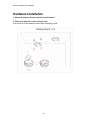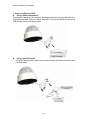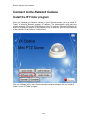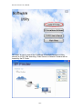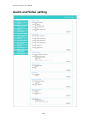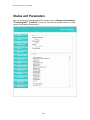
1
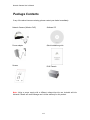
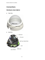
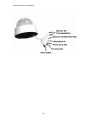
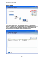
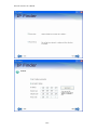
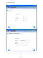
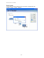
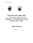
Network Camera User’s Manual
H.264 3X Optical Mini PTZ Dome
User’s manual
Version 0.4
1/67
Network Camera User’s Manual
Table of Contents
Overview...............................................................................................................3
Package Contents.................................................................................................4
Connections..........................................................................................................5
Hardware description.....................................................................................5
Hardware Installation ............................................................................................7
Connect to the Network Camera.........................................................................10
Install the IP Finder program........................................................................10
Bonjour program ..........................................................................................19
ip-discovery.com(Free DDNS service) .........................................................20
Initial Access to the Network Camera .................................................................23
Primary user’s capability .....................................................................................25
Main Screen with Camera View...................................................................25
Client Setting ...............................................................................................30
Definitions in Configuration .................................................................................32
System parameters.............................................................................................32
Security...............................................................................................................34
Network...............................................................................................................36
Access list ...........................................................................................................39
Audio and Video setting ......................................................................................42
Video record .......................................................................................................46
Stream ................................................................................................................48
Camera control ...................................................................................................50
Application ..........................................................................................................52
Storage ...............................................................................................................55
Syslog .................................................................................................................57
Status and Parameters .......................................................................................58
Maintenance .......................................................................................................59
Appendix.............................................................................................................61
A. Troubleshooting & Frequently Asked Questions......................................61
B. Technical specifications ...........................................................................67
2/67
Network Camera User’s Manual
H.264 3X Optical Mini PTZ Dome
Overview
Law in your country may prohibit the use of surveillance devices. The Network Camera
is not only a high-performance web-ready camera but also can be part of a flexible
surveillance system. It is the user’s responsibility to ensure that the operation of such
devices is legal before installing this unit for its intended use.
It is important to first verify that all contents received are complete according to the list in
the "Package Contents" chapter. Take notice of the warnings in “Quick installation guide”
before the Network Camera is installed, then carefully read and follow the instructions in
the “Installation” chapter to avoid damages due to faulty assembly and installation. This
also ensures the product is used properly as intended.
The Network Camera is accessible via the LAN or Internet connection. Connect your
Network Camera directly to a computer network or DSL modem, and with a standard
Web browser you get instant, on demand video streams. Within minutes you can set up
the Network Camera to capture a video sequence to a PC. Live video image can be
uploaded to a website for the world to see or made available only to select users on the
network.
The Network Camera is a network device and its use should be straightforward for those
who have basic network knowledge.
The Network Camera is designed for various applications including video sharing,
general security/surveillance, etc. The “How to Use” chapter suggests ways to best
utilize the Network Camera and ensure proper operations.
Minimum System Requirement
H.264 3X Optical Mini PTZ Dome
Network Environment
LAN
10/100M Ethernet
Monitoring System Recommended for Internet Explorer
System Hardware
Basic requirements
· CPU: Intel® Celeron® Dual-Core @2.70GHz or above
· Memory Size: 2 GB or above Recommended
· VGA card resolution: 1024 x 768 or above
System Requirement for Viewer & Recorder Application
Support OS
XP, Windows 7
System Hardware
1-4 cameras surveillance application
· CPU: Intel® Celeron® Dual-Core @ 2.70GHz or above
· Memory Size: 2 GB or above
· VGA card resolution: 1024 x 768 or above
3/67
Network Camera User’s Manual
Package Contents
If any of the above items are missing, please contact your dealer immediately.
Network Camera (Wired or PoE)
Software CD
Power adapter
Quick installation guide
Screws
RJ45 Female
Note: Using a power supply with a different voltage than the one included with the
Network Camera will cause damage and void the warranty for this product.
4/67
Network Camera User’s Manual
Connections
Hardware description
z
Outer View
Wired cover
Slide cover
z
Inner View
5/67
Network Camera User’s Manual
6/67
Network Camera User’s Manual
Hardware Installation
1. Attach the Network Camera with the included stand
2. Place the Camera fix it onto ceiling or wall
Use screws to fix the Network Camera onto the ceiling or wall.
7/67
Network Camera User’s Manual
8/67
Network Camera User’s Manual
3. Power over Ethernet (PoE)
z Using a PoE-enabled switch
The Network Camera is PoE-compliant, allowing transmission of power and data via a
single Ethernet cable. Follow the below illustration to connect the Network Camera to a
PoE-enabled switch via Ethernet cable.
z
Using a non-PoE switch
Use a PoE power injector (optional) to connect between the Network Camera and a
non-PoE switch
9/67
Network Camera User’s Manual
Connect to the Network Camera
Install the IP Finder program
When you installed your Network camera on your LAN environment, you may install “IP
Finder” to discover Network camera’s IP address. The Administrator must place the
product software CD into the CD-ROM drive of the PC running in Microsoft Windows. An
auto-run program will pop up (If the program is not on auto-run, go to the root directory
of the software CD and click on “autorun.exe”).
Click on “Software Utility” item, after the window contents changed, click on “Install IP
Finder” to run “IP Finder” program.
10/67
Network Camera User’s Manual
“IP Finder” is used to search the IP address of Network Cameras or Video
servers on a LAN. After searching, Video Servers or Network Cameras will be
located by the IP Finder.
11/67
Network Camera User’s Manual
Search Camera
Click search Camera button, The program will search for all family network
devices on the same LAN. After searching, the main installer window will pop up.
Click on the MAC and model name which matches the product label on your
device to connect to the Network Camera via Internet Explorer.
12/67
Network Camera User’s Manual
Setup Camera
Auto Install Wizard will be started and that it can auto guide through the
installation process. Press the “Next” button execute next process. For more
information, please refer to the Network section on page 33.
13/67
Network Camera User’s Manual
14/67
Network Camera User’s Manual
15/67
Network Camera User’s Manual
16/67
Network Camera User’s Manual
17/67
Network Camera User’s Manual
Setup Language
Click this button to choose a language for the user interface. Language options are
available in: English、Chinese、Japanese.
18/67
Network Camera User’s Manual
Bonjour program
Safari browser supports Bonjour search program the will search for all family network
devices on the same LAN.
19/67
Network Camera User’s Manual
ip-discovery.com(Free DDNS service)
1. When you want to connect the network camera over Internet, you can use the
service “ip-discovery.com”. The “ip-discovery.com” is a free DDNS server for this
camera. Make sure that the router must start UPnP and DHCP server functions.
You can get the domain name which you wish very easily after registration. In
Network page—DDNS settings of this camera, you just input the host name you
want and your e-mail address, and click “Register”, then you can have the
hostname for this camera not longer than 20 seconds if the DDNS registration
result is OK. Then you can connect to this ip camera by
*http://XXX.ip-discovery.com:@@@@
*XXX: the host name you type
*@@@@: The HTTP port (get it automatically by ip-discovery server)
User password: Default the password is last six number of the MAC. To change
“root” password at “Security configuration” can change the user password, This
“User password” is entered in the ip-discovery.com Password.
Note: You must set the ports between your router and camera manually if the registration
is failed.
20/67
Network Camera User’s Manual
2. The free server is acted as an internet IP finder. For more services from the free
Server, just running IE browser and input the host name http://ip-discovery.com/
Select language.
21/67
Network Camera User’s Manual
Current device
In other cameras in the same registered e-mail will become a group.
22/67
Network Camera User’s Manual
Initial Access to the Network Camera
(1) For the initial access to the Network Camera in Windows, the web browser may
prompt for permission to install a new plug-in for the Network Camera. This plug-in
has been registered for certificate and is used to display the video in the browser.
Users may click on
to proceed.
1. Click “Install” and “Run” ActiveX controls
23/67
Network Camera User’s Manual
2.The video will be displayed.
24/67
Network Camera User’s Manual
Primary user’s capability
Main Screen with Camera View
The main page has three parts:
1. Configuration functions: The camera can be configured using these user
interfaces.
2. Pan/Tilt/Zoom & connection control buttons: These buttons provide the
direction to control the pan and tile of camera.
3. Camera View: What the camera sees.
Click the configuration in the bottom of left column to link to the configuration page.
2
3
1
Configuration functions:
“Client Settings” Clicking on this button links you to the client setting pages,
please check the following session for more details.
“Configuration” Please notes that only the administrator can access it.
“ Language” Click this button to choose a language for the user interface.
Language options are available in: English, traditional Chinese, Simplified Chinese,
Japanese, Spanish, Portuguese, French, German, Italiano.
25/67
Network Camera User’s Manual
Camera view:
On the top of image shows the connecting type of the Network Camera and the current
date/time.
View capabilities:
Click this button to capture and save still images. The captured images will be
displayed in pop-up window. Right-click the image and choose Save Picture As to save it
in JPEG format.
1.
The button selection lets you open a digital zoom, and to control the window to
enlarge a specified area in the camera view.
2.
3.
Click this button to switch to full screen mode. Press the “Esc” key to switch back
to normal mode.
4.
5.
Click on this button freeze the video, and playing when you click again.
Click on this button stop video output.
Use this function;you can record video in your PC by browser directly. The files
format will be in MP4. Note: Due to the UAC (User Access Control) function in Windows
Vista or Windows 7, the IE browser would need to be run under the “Administrator”
privilege.
6.
7.
Click on this button adjust the audio volume & Latency.
8.
Click on this button switch Mute On/Off.
26/67
Network Camera User’s Manual
9.
Click on this button to adjust the Function “2-way audio” to be Enable/Disable.
Enable this function, request insert an external speaker. The server can play sound from
the client and receive sound from the environment and send to client.
10.
Click on this button to adjust the Microphone volume.
11.
Click on this button switch Microphone Mute On/Off.
12.“Go to” Once the Administrator has determined the preset positions; the User can
aim the camera using this control.
27/67
Network Camera User’s Manual
Pan/Tilt/Zoom & connection control buttons:
1. “Connection” User can choose Remote or Local
mode for best connection quality.
Proposal: Internet environment, switch Remote
mode.
2. “Video Stream” User can choose stream1 or
stream2.
3. “Digital Output” Clicking on the “On” or “Off”
button turns the digital output to either on or off
status.
4. “The direction buttons are” “Left”, “Right”, “Up”,
“Down”, “Cross Angles”, and “Home”. Camera returns
to center when click “Home” button
5. “Pan Angle” User can choose the angles when
the camera moves left and right each time.
6. “Tilt Angle” User can choose the angles when the
camera moves up and down each time.
7. “Iris” Adjust the iris size
8. “Pan” The camera will move from right side to left
side continuously when click the button.
9. “Patrol” The button directs the camera to patrol
among the preset positions in the patrol list, which
can be modified on the “Camera control page”. The
cycle of patrol is from 1 to Unlimit.
10. “Video Tracking” is able to track dynamic
objects within screen video.
11.“Focus/ Smart Focus” Screen auto focus.
12.”3D Auto location” Press the left key of the
mouse, and pull and choose a certain area in the picture in diagonal direction, can
enlarge this area, and put this area in the middle position of picture of controlling.
28/67
Network Camera User’s Manual
29/67
Network Camera User’s Manual
Client Setting
1. “Intranet Protocol Options” Setting camera in intranet mode of protocol.
“UDP” Select use UDP protocol connect camera.
“TCP” Select use TCP protocol connect camera.
“HTTP” Select use HTTP protocol connect camera.
2. “Internet Protocol Options” Setting camera in internet mode of protocol.
“UDP” Select use UDP protocol connect camera.
“TCP” Select use TCP protocol connect camera.
“HTTP” Select use HTTP protocol connect camera.
3. “Recording options” Users can record live video as they are watching by
clicking
start MP4 Recording on the main page. Here, you can specify the
storage destination and file name.
“Folder” Specify the storage destination for the recorded video files.
“File name prefix” Enter the text that will be appended to the front of the video
file name.
30/67
Network Camera User’s Manual
“Add date and time suffix to file name” Select this option to append the date
and time to the end of the file name.
NOTE:Protocol Options which allows choices on connection protocol between client and
server. There are three protocols choices to optimize your usage – UDP,TCP,HTTP.
The UDP protocol allows for more real-time audio and video streams. However, some
packets may be lost due to network burst traffic and images may be obscured.
The HTTP protocol allows for less packet loss and produces a more accurate video
display. The downside with this protocol is that the real-time effect is worse than that with
the UDP protocol.
The TCP guarantees the complete delivery of streaming data and thus provides better
video quality. However, the real-time effect is not as good as that of the UDP protocol.
If no special need is required, UDP protocol is recommended. Generally speaking, the
client choice will be in the order of UDP → HTTP. After the Network Camera is
connected successfully, “Protocol Option” will indicate the selected protocol. The
selected protocol will be recorded in the user's PC and will be used for the next
connection. If the network environment is changed, or the user wants to let the web
browser to detect again, manually select the UDP and TCP protocol, save, and return
HOME to re-connect.
31/67
Network Camera User’s Manual
Definitions in Configuration
Please note that only the Administrator can access the system configuration.
System parameters
Firmware version
1. “General Setting”
(1) “Host name”
The text displays the title on the top of the main page.
(2) “LED indicator”
Select turn on or turn off the led indicator.
32/67
Network Camera User’s Manual
2. “Time Setting”
(1) “Time zone”
Choose a time zone from the down arrow.
(2) “Daylight saving”
For summertime; It will be one hour ahead.
(3) “Current Time”
Network camera set the current time.
(A) “Keep current date and time”
Click on this to keep the current date and time of the Network Camera. An internal
real-time clock maintains the date and time even when the power of the system is
turned off.
(B) “Sync with computer time”
Synchronize the date and time in the Network Camera according to the local
computer.
(C) “Manual”
Adjust the date and time by the Administrator.
(D) “Adjust by NTP server”
Synchronize the time according NTP server over the Internet whenever the Network
Camera is switched on. It fails if the assigned time-server cannot be found.
(a) “NTP server” Assign the IP address or domain name of the time-server.
Leaving the text box blank connects the Network Camera to the default
time-servers.
(b) “Update interval” Select 0 ~ 23 hours update with the time on the NTP
server.
3. “DI and Do Setting”
Select Open or Ground to define the DO active state.
Remember to click on “Finish” to immediately validate the changes. Otherwise, the
correct time will not be synchronized.
33/67
Network Camera User’s Manual
Security
Security setting
The administrator account name is “root”, which is permanent and can not be deleted.
If you want to add more accounts in the Manage User column, please set a password for
the “root” account first.
1. “Change root password” Change the Administrator’s password by typing in the
new password identically in both text boxes. The typed entries will be displayed as
asterisks for security purposes. After pressing “finish”, the web browser will ask the
Administrator for the new password to access.
2. “Manage privilege” You can modify the manage privilege of operators or viewers.
Check or uncheck the item, then click finish to enable the settings.
3. “Manage user”
(1) “Add a new user” Administrators can add up to 20 user accounts.
(A) Input the new user’s name and password.
(B) Select the privilege level for the new user account. Click Finish to enable the
34/67
Network Camera User’s Manual
setting.
(2) “Delete a user” Select an existing user name. Click Finish to enable the
setting.
(3) “Update a existing user” Select an existing user name. Administrators can
modify user’s password and privilege. Click Finish to enable the setting.
Access rights are sorted by user privilege (Administrator, Operator, and Viewer). Only
administrators can access the Configuration page. Operators cannot access the
Configuration page but can use the URL Commands to get and set the value of
parameters. Viewers access only the main page for live viewing.
35/67
Network Camera User’s Manual
Network
Any changes made on this page will restart the system in order to validate the changes.
Make sure every field is entered correctly before clicking on “finish”
Network Setting
“LAN” & “PPPoE”
The default type is LAN. Select PPPoE if using ADSL
1. LAN
The default status is Get IP address automatically. This could be tedious to perform
software installation whenever the Network Camera starts. Therefore, once the network
is set, especially for the IP address should be entered correctly. Select Use fixed IP
address then the Network Camera will skip installation. The Network Camera will
automatically restart and operate normally after a power outage. You can run IP installer
to check the IP address assigned to the Network Camera if the IP address is forgotten,
36/67
Network Camera User’s Manual
or you can use the UPnP function provided by the Network Camera (MS Windows XP
provides UPnP function at My Network Place).
(1) “Get IP address automatically”
(2) “Use fixed IP address”
- “IP address”: This is necessary for network identification.
- “Subnet mask”: This is used to determine if the destination is in the
same subnet. The default value is “255.255.255.0”.
- “Default router”: This is a gateway used to forward frames to
destinations in a different subnet. Invalid router setting will fail the
transmission to destinations in different subnet.
- “Primary DNS”: The primary domain name server that translates
hostnames into IP addresses.
- “Secondary DNS”: Secondary domain name server backups the Primary
DNS.
- “Enable UPnP presentation & port forwarding”: Enable UPnP ability.
- “Http port” This can be typed besides the default Port 80. Once the port is
changed, the users must make sure the change for the connection is successful.
For instance, when the Administrator changes the HTTP port of the Network
Camera which IP address is 192.168.0.20 from 80 or 1025 to 65535, the users
must type in the web browser “http://192.168.0.20:8080” instead of
“http://192.168.0.20”.
- “RTSP Port” RTSP port can be typed besides the default Port 554
- “RTP Port” The RTP port can be typed besides the default Port 54
Note:Please set Video RTP port in even number after default value port 54. Then,
Video RTCP pot、Audio RTP port、Audio RTCP port will automatically set the
values in ascending.
- “RTSP Streaming access names” The RTSP streaming currently supports
video only, audio only, and audio/video. To use the audio/video stream, type the
URL as“rtsp://61.30.125.43/liveN.sdp”.
2. PPPoE
If using the PPPoE interface, you should fill the following settings from ISP.
(1) “User name”: The login name of PPPoE account
(2) “Password”: The password of PPPoE account
(3) “Confirm password”: Input password again for confirmation
DDNS Setting
1. “Enable DDNS” This option turns on the DDNS function.
2. “ip-discovery” In the Register column, fill in the Host name (xxxx.ip-discovery),
Email, Key, and Confirm Key, then click Register. After a host name has been
successfully created, a success message will be displayed in the DDNS Registration
Result column and messaging E-mail.
3. “3rd party DDNS” This is enable or disable 3rd party DDNS.
4. “Provider” The provider list contains hosts that provide DDNS services. Please
connect to the service provider’s website to make sure the service charges.
5. “Host Name” If the User wants to use DDNS service, this field must be filled.
Please input the hostname that is registered in the DDNS server.
37/67
Network Camera User’s Manual
6. “User name” The Username or E-mail field is necessary for logging in the DDNS
server or notify the User of the new IP address.
Note: when this field is input as “User name”, the following field must be input as
“Password”.
7. “Password” Please input the password or key to get the DDNS service.
8. “finish” Click on this button to save modify settings for the DDNS service.
38/67
Network Camera User’s Manual
Access list
Access list setting
1. How to control access permission by verifying the client PC’s IP
address. General Settings.
General Settings
39/67
Network Camera User’s Manual
◆ Add a rule to configure an Allowed/Denied list: Click Add to add a rule
to Allowed/Denied list.
There are three types of rules for user to set up:
“Single” This rule allows the user to add an IP address to the Allowed/Denied list.
For example:
“Network” This rule allows the user to assign a network address and corresponding
subnet mask to the Allow/Deny List. The IP address is written in the CIDR format.
For example
40/67
Network Camera User’s Manual
“Range” This rule allows the user to assign a range of IP addresses to the Allow/Deny
List. This rule is only applied to IPv4.
For example:
41/67
Network Camera User’s Manual
Audio and Video setting
42/67
Network Camera User’s Manual
General Setting
1. “Color mode” Select use color or monochrome video display.
2. “Video orientation” The orientation of video
(1) “Flip” Vertically rotate the video.
(2) “Mirror” Horizontally rotates the video.
3. “Environment” The orientation of video
(1) “indoor” This option is usually selected when the Network Camera is placed
in indoor environments.
(2) “outdoor” This option is usually selected when the Network Camera is placed
in outdoor environments.
4. “Power freq.” Select 50 Hz or 60Hz power line frequency.
※The fluorescent light will flash according to the power line frequency that
depends on local utility. Change the frequency setting to eliminate uncomfortable
flash image when the light source is only fluorescent light.
Video Setting
1. “Contrast” Adjust the image contrast level, which ranges from -5 to +5. The default
value is set to 0.
2. “Brightness” Adjust the image brightness level, which ranges from -5 to +5. The
default value is set to 0.
3. “Saturation” Adjust the image saturation level, which ranges from -5 to +5. The
default value is set to 0.
4. “Sharpness” Adjust the image sharpness level, which ranges from -5 to +5. The
default value is set to 0.
5. “EV” Exposure value represent the expected target value of the luminance of
the weighting result of AE windows in the image and its tolerance as offset.
6. “Gain” In the slide bar of Gain, there are also two sliders, which represent the
limitations to control the maximum gain value and the minimum one, respectively.
Normally, the minimum value is to 1x for better quality.
43/67
Network Camera User’s Manual
Exposure setting
Here it provides 3 mode: Auto, Backlight and Customized. Auto and
Backlight modes are 2 default settings for general purpose and backlight scene,
respectively.
Customized mode relates to the grid window above can be pointed on for
interesting areas. Within the mode Customized, 16*15 grids windows can be
chosen to match where/what you are interested in. Push down left-button of
mouse and drag to draw the grids for interesting areas, or push down right-button
of mouse and drag to clean the grids for insignificant areas.
“Target Luminance and Offset”
These two slide bar, Target Luminance and Offset represent the expected
target value of the luminance of the weighting result of AE windows in the image
and its tolerance as offset. For example, target luminance is set to 100 and target
offset is set to 20 that means the average luminance of the AE window should be
in the range from 80 to 120 (100±(10. When the actual luminance does not meet
this range, the AE function will adjust shutter and gain to meet it as possible. In
some extreme cases, it cannot reach the target because the environment is too
bright or dark. When the environment is not consistent, e.g. with big moving
objects, and the offset is too narrow, the AE will act more frequently that will
cause the background of view inconsistent. The offset value is recommended to
44/67
Network Camera User’s Manual
set 15~25% of target luminance.
“Gain”
In the slide bar of Gain, there are also two sliders, which represent the limitations
to control the maximum gain value and the minimum one, respectively. Normally,
the minimum value is to 1x for better quality. It is not allowed if the maximum
slider and the minimum one are set to the same value without adjustable interval.
Besides, the noise will be increased if the actual gain is too large. When the max.
slider is dragged over sensor's max. gain, the slide bar will become deep blue to
represent it will apply Mozart 3s digital gain, which extend the max. gain for very
low light.
“Shutter Speed”
There are 2 fields, minimal and maximal time, for the range of Shutter Speed.
The precision of the parameter is 1/1000000 sec., but it is NOT actual precision
of the shutter speed of the sensor. The actual precision of the shutter speed
depends on each sensor’s specification. Here it will be rounded to approach
sensor’s effective exposure time. To avoid flickering or banding phenomenon
under fluorescent light, the actual shutter speed will be locked at 1/120, 1/60,
1/30 if Power Line Frequency is 60Hz, or 1/100, 1/50, 1/25 if Power Line
Frequency is 50Hz. The setting of Power Line Frequency is on the sub-tab Video
and Audio. The exposure may not be stable if the maximum value and the
minimum one are set to the same value without adjustable interval. Besides, the
frame rate will drop down if the actual shutter speed is too slow to meet expected
frame rate.
Noise reduction
Provides 2D and 3D features.
Wide Dynamic Range
Enable Wide Dynamic Range auto in different level to improve the exposure
when both bright and dark areas simultaneously in the field of view of the camera.
The default is off.
Infrared Led Setting
1. “Infrared LED Control” IR led for Day and Night (Option). User can turn on/off
the built-in IR led. This function is very useful under low illumination environment.
(1) “Auto” Select IR sensitivity from 0 to 4.
(2) “Manual” Turn on/off the IR led manually.
- “Turn on” Turn on led
- “Turn off” Turn off led
2. “Low lux mode” The video quality will be improved when the camera is in low
lux environment.
(1) “Disable dark mode” Disable low lux mode.
(2) “Enable dark mode” Enable low lux mode.
45/67
Network Camera User’s Manual
Audio Setting
1. “Mute” Audio mute.
2. “Microphone ” Internal microphone or external microphone select.
3. “Mic Volume” Adjust microphone volume, which ranges from 1 to 64.
Video record
Schedule mode
(1) “Every day” Enable/Disable every day application.
(2) “Week day” Enable/Disable week day application.
(3)“Selected day” Enable/Disable selected day application.
Schedule information
(1) Enter the “Start time” and “Stop time” for day mode.
Note that the time format is [hh:mm] and is expressed in 24-hour clock time. By
default, the start and end time of day mode are set to 01:00:00 and 23:59:59.
46/67
Network Camera User’s Manual
(2)“Sun”/“Mon”/“Tue”/“Wed”/“Thu”/“Fri”/“Sat” Select the days of the
week to perform the application.
(3) “Start day” and “Start time” as the start timing the time. “End day” and
“End time” as the end timing the time
(4) “Enable cyclic recording” The cyclic recording function is enabled, during the
transaction stage when a storage space is full and the incoming streaming data is about
to overwrite the previously saved videos.
Record parameters
(1)Source: Select a stream for the recording source.
(2)Recording interval: Select the recording time interval.
(3)Prefix file name: You can setting the file name, and enable or disable to
add the date and time on file name.
Response mode There are two choices of server types available: NAS, Micro SD
Card. Select the item to display the detailed configuration options.
(1)”NAS”
--“NAS server address” Enter IP address of the NAS server.
--“NAS shared directory” Enter the NAS shared directory path.
--“Workgroup” Enter the NAS workgroup parameter.
--“User account” Enter the login name of the NAS account.
--“User password” Enter the password of the NAS account.
Note: Video record with the Application must be set to the same shared directory
path. If you would like do detail recording settings or multi-channel recording, please
install bundled 64CH recording software in CD.
47/67
Network Camera User’s Manual
Stream
Audio codec setting
(1)“Audio codec type” There are two choices of audio codec types
available: ”AMR”、 “AAC” and ”G.711”.
(2) “Bit rate”
-- “AMR” The bit rates are selectable at the following rates: 4.75Kbps,5.15
Kbps,5.9 Kbps,6.7 Kbps,7.4 Kbps,7.95 Kbps,10.2 Kbps and 12.2 Kbps.
-- “AAC” The bit rates are selectable at the following rates:
8Kbps,16Kbps, 24Kbps and 32Kbps.
-- “G.711” pcmu and pcma.
48/67
Network Camera User’s Manual
Video codec setting
(1) “Select Stream” The Network Camera supports “Stream 1”and “Stream 2”.
(2) “Video codec” The Network Camera supports three kind of video
compression mode: “H.264” or “MPEG4” or “MJPEG”. User can choose one of
these compression modes based on requirement or application
(3) “Video size” Click the down arrow to choose the quality of image
(4) “Connection type” User can select this button to choose the better video
& links quality. (Internet mode or Intranet mode)
(5) “Frame rate” This limits the maximal refresh frame rate per second. Set the
frame rate higher for a smoother video quality.
(6) “Intra frame period” Determine how often to plant an “I frame”. The shorter
the duration, the more likely you will get a better video quality, but at the cost of
higher network bandwidth consumption.
(7) “Video Quality type” Setting optimizes bandwidth utilization and video quality.
-- “Constant bit rate” User can adjust the video quality from 20 Kbps to 12
Mbps.
-- “Fixed quality” user can select from lowest quality to get best quality
according. The “Quality” are selectable at the following rates: From 1 to 20.
Snapshot and time display setting
Adjust the photo size specifications and choose whether to mark time on
the video and photo.
49/67
Network Camera User’s Manual
Camera control
Camera control
The pan and tilt functions can be controlled with these buttons. The “Left” button
controls the camera to the left; the “Right”, “Up”, and “Down” buttons control the
camera accordingly.
(1) “UL”, “UR”, “LL” and “LR” buttons control the camera to an oblique angle.
And “Home” button controls the camera to the center.
(2)“Pan angle” This sets the range of the horizontal movement of the camera. The
larger value is setting, the larger movement of “Left” or “Right” is performing by the
camera.
(3) “Tilt angle” This sets the range of the vertical movement of the camera. The
larger value is setting, the larger movement of “Up” or “Down” is performing by the
50/67
Network Camera User’s Manual
camera.
(4) “Patrol cycle” It is the cycle of patrol function.
(5) “Auto pan speed” This defines the speed of auto panning. The larger value is
setting, the faster speed will run by the camera.
(6) “Auto patrol speed” This defines the speed of auto patrol. The larger value is
setting, the faster speed will run by the camera.
Preset point setting
(1) “Set the home position”
--“Set default value as home position” Restore home position to original
default’s home by clicking on this button.
--“Set the current position as home position” Click on the button will set the
current aimed position as home of the Network Camera. Each time the Network
Camera reboots or finishes calibration, it will automatically aim to the defined home
position
(2) “Set the auto pan range”
--“Set default value as auto pan range” Restore auto pan range to original
default’s auto pan range by clicking on this button.
--“Set the auto pan range manually” Click on the button will set the auto pan
range of the Network Camera.
(3)” Add or delete a preset point”
--“Add current point as a preset point” If the User wants to save the current
view as a preset location, enter a name to each of the current video view on
“Preset points” and click on the “Finish” button. The camera allows for 20
preset locations.
--“Delete a preset point from below” This keeps a list for preset positions.
Clicking on the “Finish” button will remove the current selected position from the
preset list.
Patrol list setting
(1) ”Preset points” The preset points box list all preset points. User must use
to drag the preset points to “Patrol list” box when the action is recognized
the “Patrol list” box change to red.
(2) “Patrol list” The Patrol list box list all patrol points. User use the drag to
adjust of the patrol point(Up or down). Dwelling time (sec)” The stop time of
each preset location during auto patrols of the Network Camera.
(3) “Remove patrol point” The remove patrol point box will remove the patrol
point.
51/67
Network Camera User’s Manual
Application
Schedule mode
(1) “Every day” Enable/Disable every day application.
(2) “Week day” Enable/Disable week day application.
(3) “Selected day” Enable/Disable selected day application.
Schedule information
(1) Enter the “Start time” and “Stop time” for day mode.
Note that the time format is [hh:mm:ss] and is expressed in 24-hour clock time. By
default, the start and end time of day mode are set to 01:00:00 and 23:59:59.
(2) “Sun”/“Mon”/“Tue”/“Wed”/“Thu”/“Fri”/“Sat” Select the days of the
52/67
Network Camera User’s Manual
week to perform the application.
(3) “Start day” and “Start time” as the start timing the time. “End day” and
“End time” as the end timing the time
Trigger mode
(1) “Video motion detection” Enable/Disable video motion application
(2) “Periodically” This option allows the Network Camera to trigger
periodically for every other defined minute.
(3) “Video Tracking” is able to track dynamic objects within screen video.
-- “Tracking level” 1 to 5 level the lower the number the more sensitive.
parameters
(1) “Motion parameters”
Higher sensitivity and small threshold will allow easier motion detection.
(2) “Period parameters” This option allows the Network Camera to trigger
periodically for every other defined seconds. Up to 999 seconds are allowed.
Media mode
There are four choices of media types available: “Snapshot”, “Message”
“Record(Motion Detection only)” and “System log”.
Snapshot & Record file setting
You can setting the file name, and enable or disable to add the date and time
on file name.
Response mode
There are four choices of server types available: Email, FTP, NAS, and SD Card
storage. Select the item to display the detailed configuration options.
(1)“Email”
-- “Email security mode” : If your SMTP server requires a secure connection
(SSL or TLS), check This server requires a secure connection (SSL or TLS).
-- “Sender email” address: Enter the email address of the sender.
-- “Recipient email” address: Enter the email address of the recipient.
-- “Server address” Enter the domain name or IP address of the email
server.
--“User name” Enter the user name of the email account if necessary.
--“Password” Enter the password of the email account if necessary
--“Server port” The default mail server port is set to 25. You can also
manually set another port.
(2)”FTP”
-- “Server address” Enter the domain name or IP address of the FTP server.
-- “Server port” By default, the FTP server port is set to 21.
-- “User name” Enter the login name of the FTP account
-- “Password” Enter the password of the FTP account.
-- “FTP folder name” Enter the folder where the media file will be placed. If
the folder name does not exist, the Network Camera will create one on the FTP
server.
(3)”HTTP ”
-- “URL” Enter the URL of the HTTP server.
-- “User account” Enter the user name if necessary.
53/67
Network Camera User’s Manual
-- “User password” Enter the password if necessary.
(4)”NAS”
--“NAS server address” Enter IP address of the NAS server.
--“NAS shared directory” Enter the NAS shared directory path.
--“Workgroup” Enter the NAS workgroup parameter.
--“User account” Enter the login name of the NAS account
--“User password” Enter the password of the NAS account.
Note: Video record with the Application must be set to the same shared directory
path. If you would like to do detail recording settings or multi-channel recording, please
install bundled 64CH recording software in CD.
54/67
Network Camera User’s Manual
Storage
Manage the storage device.
1
2
3
Storage Status
Here show the storage device information.
NAS server setting
(1) “NAS Host name” Choose and input the NAS Host name of this camera.
(2) “Workgroup” Input the name of Workgroup. You can see the NAS Host name
you input in the same workgroup with your PC. Then you can connect to this
device and download the files easily from SD card which is inserted to this
55/67
Network Camera User’s Manual
camera.
File operation
Move the mouse over the file. Press the mouse right button that Right-click menu is
displayed. You can delete files.
Move the mouse over the directory. Press the mouse left button that the file structure
expand. Press the mouse right button that Right-click menu is displayed. You can
choose upload or delete files.
NOTE:Allow the user to upload or delete files when the storage device is not writeprotected. If the SD card can’t be detected, please link to the following URL:
http://www.sdcard.org/consumers/formatter to download the “SD Formatter Kit”
formatting your SD card.
56/67
Network Camera User’s Manual
Syslog
The Network camera supports log the system messages on remote server.
The protocol is compliant to RFC 3164. If you have external Linux server with sys log
service, use “-r” option to turn on the facility for receiving log from remote machine. Or
you can use some software on Windows that is compliant to RFC 3164. An example is
Kiwi Syslog Daemon. Visit http://www.kiwisyslog.com/kiwi-syslog-daemon-overview/.
Check “Setup” and “Enable” then input the “IP address” and “port” number of the log
server to enable the remote log facility.
In the “Current log”, it displays the current system log file. The content of the log
provides useful information about configuration and connection after system boot- up.
“finish” Click on this button to save modify settings.
57/67
Network Camera User’s Manual
Status and Parameters
User can find a lot of information about the system such as “Upnp port forwarding”,
“Traversing NAT”, “Public IP”, and so on. User also can get the number of current
viewer of the Network Camera here.
58/67
Network Camera User’s Manual
Maintenance
1. “Reboot system” The “Reboot” button will reboot the Network Camera. It’s useful
while the Network Camera got problem.
2. “Restore system” Click on “Restore” button on the configuration page to restore
the factory default settings. Restore all settings to factory default except settings in
“Network type ” and “Root Password”. The system will restart and require the installer
program to set up the network again.
3. “Export/Import file”
-- Export setting backup file: Click to export all parameters for the device and
user-defined scripts.
-- Upload setting backup file: Click Browse… to upload a setting backup file. Please note
that the model and firmware version of the device should be the same as the setting
59/67
Network Camera User’s Manual
backup file. If you have set up a fixed IP or other special settings for your device, it is not
suggested to upload a settings backup file.
4. “Upgrade firmware” Select the firmware file and click upgrade button. Please be
aware that you should not turn off the power during updating the firmware and wait for
finish message.
Warning: The upgrade firmware procedure cannot be interrupted. If the power
and/or network connection are broken during the procedure, it might possibly
cause serious damage to the Network Camera.
Note: When upgrade firmware please wait for 120~210 seconds, and then you
can connect to Network Camera again. The system will restart and require the
installer program to set up the network again.
60/67
Network Camera User’s Manual
Appendix
A. Troubleshooting & Frequently Asked Questions
Q1: Status led does not light up.
A1: First, make sure that「Configuration>System>Turn off the LED indicator」is disabled.
If it is, check the item, and the led should light up. Second, if red led does not light up,
please check that the power adapter in the package is plugged correctly. And last, if
green led does not light up; please check that category 5 UTP cable is plugged correctly.
If the problem is still not solved, please contact your dealer for further help.
Q2: What kind of Ethernet cable is used by network camera?
A2: The network Camera uses Category 5 UTP cable allowing 10 and/or 100 Base-T
networking.
Q3: The Network Camera will be installed and work if a firewall exists on
the network?
A3: There are two way to set up the IP camera at Internet.
(1) By UPnP Port Forwarding
1. Select an IP router. It must support UPnP port forwarding and enable this function
first!!
2. Connect camera RJ45 cable to IP router and the router is also connected to Internet.
3. Plug power cord to camera.
4. Go to camera Network page. Enable UPnP port forwarding
5. Check camera status, we can see the ports had been successfully opened!
61/67
Network Camera User’s Manual
6.Type IP address:8080 at browser. Then you can see camera through Internet.
7.You can also type the ddns name at below label of camera on browser URL field. For
example, you may type ah00001.ip-discovery.com:8080.
(2) By Setting Port Forwarding Manually
1. Select a router. Set the port forwarding as following.
62/67
Network Camera User’s Manual
PS. Port 80 is HTTP Port, port 53 is stream port, port 554 is RTSP port. and port 443 is
HTTPS port.
2.Go to camera Network page. Disable UPnP port forwarding function.
63/67
Network Camera User’s Manual
3. Type IP address at browser. Then you can see camera through Internet.
4. You can also type the ddns name at below label of camera on browser URL field. For
example, you may type ah00001.ip-discovery.com.
Note: The firewall software at PC may block the transfer of network camera.
Please remove or stop the kind software.
Q4: How can I find the network camera in the local area network?
A4: By using the IP Finder2 program or using UPnP to find it.
Q5: IP Finder2 program cannot find Network Camera in the local area
network at first time?
A5: Make sure the subnet of network camera is same as your PC. If the local area
network supports DHCP, the camera is “Get IP address automatically” in the “Network”
page default. If the local area network does not support DHCP, change your PC IP
address to “192.168.0.xxx”.
Q6: How can I restore the network camera to default value?
A6: Use a gem clip to press on the inside button. Network camera begins to restore
64/67
Network Camera User’s Manual
default value. You can also press the button “Factory” in “Maintenance” page to restore
the default value.
Q7: I cannot play the recorded video file.
A7: Install the audio codec in the CD, and use the Windows Media Player 10 or later to
play the *.ASF or *.AVI file recorded by the network camera.
Q8: Infrared led does not light up?
A8: Check 「 Configuration>Audio and Video>Infrared LED Control 」 is “Auto” or
“Manual》Turn on”.
Q9: The network camera cannot focus accurately.
A9:
(1) The lens is dirty or dust is attached. Clean the lens with lens cleaner. And then adjust
the camera focus manually.
(2) The image may be out of focus. If the object is too near, move the object away from
Network Camera.
Q10: The cover of network camera is warm. Is it normal?
A10: Network camera is a precision device. The internal material has the operational
temperature, and it is normal when user touch the cover feels warm. It is recommended
to put the network camera at aired place, and not put at any other device.
Q11: What is the scope of wireless network camera connecting AP?
A11: The scope of wireless connection is different form the environment. The possible
interference is (1) the direction of antenna (2) the material and architecture of building (3)
the temperature of environment (4) the position of the network camera.
Q12: The process of upgrade firmware abort.
A12: Contact your dealer for further help.
Q13: Cannot access the login page and other web pages of Network
Camera from Internet Explorer
65/67
Network Camera User’s Manual
A13:
• May be due to the network cable. Try correcting your network cable and configuration.
Test the network interface by connecting a local computer to the Network Camera via a
crossover cable.
• Make sure the Internet connection and setting is ok.
• Make sure enter the IP address of Internet Explorer is correct. If Network Camera has
a dynamic address, it may have changed since you last checked it.
• Network congestion may prevent the web page appearing quickly. Wait for a while.
The IP address and Subnet Mask of the PC and Network Camera must be in the same
class of the private IP address on the LAN.
• Make sure the http port used by the Network Camera, default=80, is forward to the
Network Camera’s private IP address.
• The port number assigned in your Network Camera might not be available via Internet.
Check your ISP for available port.
• The proxy server may prevent you from connecting directly to Network Camera, set up
not to use the proxy server.
• Confirm that Default Gateway address is correct.
• The router needs Port Forwarding feature. Refer to your router's manual for details.
• Packet Filtering of the router may prohibit access from an external network. Refer to
your router's manual for details.
• Access Network Camera from the Internet with the global IP address of the router and
port number of Network Camera.
• Some routers reject the global IP address to access Network Camera on the same
LAN. Access with the private IP address and correct port number of Network Camera.
• When you use DDNS, you need to set Default Gateway and DNS server address.
• If it’s not working after above procedure, reset Network Camera to default setting and
installed it again.
• Maybe the IP Address of the Network Camera is already being used by another device
or computer.
• If the problem is not solved, the Network Camera might be faulty. Contact your dealer
for further help.
66/67
Network Camera User’s Manual
B. Technical specifications
- System
- Camera specification
RAM : 4GB DDR
ROM : 16MB flash ROM
Type 1/2.8 Sony CMOS sensor IMX222
Resolution: 1920x1080
- IR Led
- Lens
Auto/Manual mode, 15~20M visible
3X optical zoom lens, auto iris, auto focus
Spectral band width 42nm, Peak emission wavelength f = 3mm ~ 9mm, F1.8
850nm
Fov(D), 136° ~ 39°
Daylight sensor, angle +/-65, wave length 400~700nm
- Protocol
- Video Resolution
TCP/IP, HTTP, SMTP, FTP, DDNS, UPnP, Telnet,
NTP, PPPoE, DNS, DHCP and RTSP
Up to 30 frames at 1920*1080, 1280x1024,
1280x800, 640x480, 320x240 and 176x144
- Audio
G.711/AMR/AAC,Omni-directional Microphone
Support 2 way audio
- Algorithm supported
- I/O Interface
H.264/MPEG4/MJPEG multi-codec for streaming
video
JPEG for still image
RJ-45
DI
DO
Audio in
Audio out
DC Power
Micro SD slot(inside camera)
- Physical
10 baseT or 100 baseT Fast Ethernet auto
negotiation
- Pan/Tilt angle
- Power
Support auto tracking function
Support multi - direction movement
Pan : 250°
Tilt : 75°
Input: 100-240VAC, 50/60Hz, 0.7A
Output: 12VDC, 1.5A
Consumption: Max 8 W
Support 802.3af compliant Power over Ethernet
- EMI & Safety
- Dimension
CE, FCC
Height : 69mm, Diameter : 92mm
- Operating Environment
- Weight
Temperature : 0 ~ 40℃
Humidity : 85% RH
NET. 400g
67/67