1
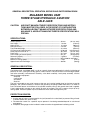
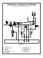
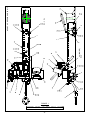
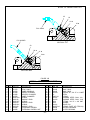
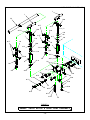
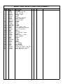
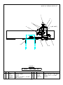
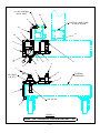
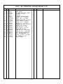
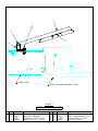
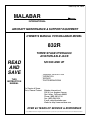
Date: July 29, 2010
MALABAR
INTERNATIONAL
AIRCRAFT MAINTENANCE & SUPPORT EQUIPMENT
OWNER’S MANUAL FOR MALABAR MODEL
832R
THREE STAGE HYDRAULIC
AVIATION AXLE JACK
READ
AND
SAVE
THIS
INSTRUCTION
MANUAL
S/N 929 AND UP
* GENERAL DESCRIPTION
* OPERATION
* SERVICE
* PARTS BREAKDOWN
For Service & Spare
Parts, Please Contact:
Malabar International
220 W. Los Angeles Avenue
Simi Valley, California 93065
Phone: (805) 581-0116
Fax: (805) 584-1624
E-mail: [email protected]
Web site: http://www.malabar.com
OVER 65 YEARS OF SERVICE & EXPERIENCE
© 2002 Malabar International. All rights reserved. Permission to reproduce all or part of this material must be obtained from Malabar International.
GENERAL DESCRIPTION, OPERATION, SERVICE AND PARTS BREAKDOWN
MALABAR MODEL 832R
THREE STAGE HYDRAULIC AVIATION
AXLE JACK
CAUTION:
AIRCRAFT MANUFACTURER’S SPECIFICATIONS AND INSTRUCTIONS MUST BE FOLLOWED. IN THE EVENT OF CONTRADICTION
BETWEEN AIRCRAFT MANUFACTURER’S SPECIFICATIONS AND
MALABAR’S, AIRCRAFT MANUFACTURER’S SPECIFICATIONS WILL
PREVAIL.
SPECIFICATIONS:
Rated Capacity-------------------------------------------------------------------------------Low Height ------------------------------------------------------------------------------------Hydraulic Lift----------------------------------------------------------------------------------Extension Screw-----------------------------------------------------------------------------Total Extended Height ---------------------------------------------------------------------Oil Pressure at Rated Capacity ----------------------------------------------------------Safety Pop-off Valve set at ---------------------------------------------------------------Proof Load ------------------------------------------------------------------------------------Floor Loading at Rated Capacity --------------------------------------------------------Reservoir Capacity--------------------------------------------------------------------------Hydraulic Fluid -------------------------------------------------------------------------------Maximum Towing Speed ------------------------------------------------------------------Approximate Jack Net Weight ------------------------------------------------------------
35 tons
(31.8 m. tons)
7 inches
(178 mm)
12 inches
(305 mm)
3 inches
(76 mm)
22 inches
(559 mm)
6770 psig
(476 kg/sq cm)
38.5 tons
(34.9 m. tons)
52.5 tons
(47.6 m. tons)
651 psi
(46 kg/sq cm)
2 gallons
(7.6 liters)
MIL-H-5606 or equivalent
5 mph
(8 km/h)
360 lbs
(163 kg)
GENERAL DESCRIPTION:
The Malabar Axle Jack Model 832R is a 35 ton capacity three stage telescoping hydraulic jack designed
primarily for use in jacking the landing gear of various aircraft. The jack consists of a three stage cylinder
and base assembly, frame/reservoir assembly, valve block assembly, hand pump assembly, and the
following optional equipment:
* Air pump
* Load gauge
* Air retract
* Rain hat
The jack is mounted on two swivel casters at the rear and a spring loaded wheel at the front to provide
portability. The cylinder assembly is raised off the ground by the spring loaded wheel when it is under no
load. The wheel retracts and the base of the cylinder assembly rests on the ground when load is applied.
A tow handle readily connects to tow vehicle for ease of transport. The jack is rated at 5 mph (8 km/h)
towing speed. Excessive speed may cause excessive wear and/or damage to the jack.
PROTECTION DEVICES:
1. A safety pop-off valve is incorporated in the jack (located in the valve block) to prevent lifting of loads
in excess of 38.5 tons (34.9 m. tons).
2. The extension screw has a positive stop to prevent it from being extended beyond its safe thread
engagement.
3. An optional load gauge can be installed in order to monitor the approximate load being raised.
-1-
PREPARATION FOR USE:
1. The jack is shipped without hydraulic fluid in the reservoir. Do not operate air or hand pumps until
reservoir is filled will hydraulic fluid MIL-H-5606 or approved equivalent. Remove filler cap and fill
reservoir to mark on dipstick (reservoir capacity is approximately 2 gallons/7.6 liters). Plungers must
be fully retracted before filling reservoir. Replace filler cap.
2. Open release valve and operate hand pumps a few strokes to bleed all air trapped under hand
pumps.
3. Close release valve and operate hand pump to raise plungers approximately 1 inch.
4. Open release valve to retract plungers fully to bleed all air trapped under jack plungers. Close release
valve.
PRE-OPERATION INSPECTION:
Each time the jack is to be used, inspect the following:
1. Check jack structure for rigidity. Make sure all bolts are tightened.
2. Check hydraulic line connections for leaks. Tighten as required.
3. Check for hydraulic fluid leaks around the cylinder assembly, reservoir, air pump and hand pumps.
4. Check hand pumps for proper operation.
5. Check caster wheels for proper operation.
6. Check reservoir fluid level with jack plungers fully retracted.
OPERATION:
1. Position the jack under the appropriate jacking pad of the aircraft.
CAUTION:
DO NOT EXTEND EXTENSION SCREW AGAINST AIRCRAFT JACK
PAD WITH THE PLUNGERS FULLY RETRACTED.
2. Raise the extension screw by turning counterclockwise until the ship adapter is 1/2" to 1" from aircraft
jacking pad or as far as the screw will travel (3 inches maximum).
3. Close the release valve located in front of the frame/reservoir assembly.
CAUTION:
ON JACK EQUIPPED WITH AIR PUMP, AIR RELIEF VALVE MUST BE
INSTALLED AT ALL TIMES. IF AIR RELIEF VALVE IS REMOVED, IT IS
POSSIBLE TO OVER PRESSURIZE THE PNEUMATIC SYSTEM WHICH
COULD CAUSE EQUIPMENT FAILURE AND POSSIBLE BODILY
INJURY.
4. On jack equipped with air pump, connect air supply (90-125 psig) to the 1/4 NPT air inlet located near
the air valve (A minimum of 17 scfm is required for the air pump). Air relief valve must be properly
installed. Do not attempt to remove air relief valve.
5. The jack is equipped with two hand pumps. One with 3/4 inch diameter pump plunger for rapid raising
of jack plungers under low pressure and one with 7/16 inch diameter pump plunger for high pressure
operation. The hand pumps can be operated by placing pump handle over the end of the pump
fulcrum and operating either the low or high pressure hand pump.
6. Operate air valve or either hand pump to raise plungers until the ship adapter contacts the jacking
pad. Note: A small amount of fluid wetting is normal on manual hand pump plungers. Periodically
clean to remove accumulated grease or foreign material.
7. Insure ship adapter and jacking pad are correctly mated.
8. To raise the load:
a. Operate the air valve or either hand pump as required.
b. Do not lift a load greater than the rated capacity of 35 tons (31.8 m. tons). The approximate load
being lifted can be read in tons on the load gauge. Read load on lower stage scale when only
outer plunger is extended. Read load on center stage scale when center plunger is extended.
-2-
Read load on upper stage scale when inner plunger is extended. Fluid pressure in psig may be
read on outer scale for gauge calibration.
9. To lower the load:
a. Slowly open the release valve to lower the load. The speed of lowering is controlled by the amount
the release valve is open. Note: Do not open release valve more than one and one- half turns
counter-clockwise.
10. Fully lower jack plungers. Lower extension screw. Close release valve. Cover jack when not in use.
SERVICING:
Servicing the jack consists primarily of the following:
1. When in use, the reservoir should be kept at the proper hydraulic fluid level. Check with plungers fully
retracted.
2. Grease casters and wheel as required.
3. Lubricate hand pump pivot pins and tow handle linkage.
4. If the jack has been put into storage or has not been used, the plungers must be fully extended and
retracted every 90 days to exercise the seals. A portion of the lift should be operated by the air pump
and a portion by the hand pumps.
DISASSEMBLY INSPECTION:
CAUTION: THE SAFETY POP-OFF VALVE, LOCATED IN THE VALVE BLOCK,
SHOULD NOT BE REMOVED UNLESS ABSOLUTELY NECESSARY.
THE VALVE IS SET AND SEALED AT THE FACTORY TO BY-PASS
HYDRAULIC FLUID BACK TO THE RESERVOIR AT 5-10% ABOVE
THE RATED CAPACITY OF 35 TONS. IF ADJUSTMENT IS REQUIRED,
SEE PROCEDURE UNDER TESTING (SEE SHEET 4).
When necessary to disassemble the jack, drain all hydraulic fluid from reservoir and carefully inspect the
following:
1. Inspect interior walls of jack cylinder, plungers and hand pump cylinders for smoothness and freedom
from rust, nicks, scratches and excessive wear.
2. Inspect exterior walls of jack plungers for smoothness and freedom of rust, pits and excessive wear.
3. Check extension screw, cylinder, plungers, etc., for corrosion, wear and condition of threads.
4. Verify that the extension screw has a positive stop to prevent it from being extended beyond its safe
thread engagement.
5. Inspect packings, seals, gaskets and wipers in the cylinder assembly and hand pumps for cuts,
scratches, deterioration and distortion.
6. Inspect stop ring for excessive scoring and/or wear.
7. Check hand pump oil screens by removing valve block and verifying cleanliness.
8. Inspect valves and valve seats in the valve block for scratches, dents and proper seating of the balls.
9. Inspect all pivot pins for wear, cracks, pits or evidence of damage or pending damage.
10. Inspect all areas for excessive dirt, oil, dust and chips.
OVERHAUL INSTRUCTIONS:
No definite time schedule can be established for the overhaul of the jack for replacement of the various
moving parts. The number of times the jack is raised and lowered and the amount of load raised at each
operation materially affect the life of the working parts. Do not overload the jack. Overloading is
dangerous, will hasten the need for overhaul and may damage the jack. During overhaul, replace all parts
that do not pass disassembly inspection requirements. Regardless of apparent condition, replace all parts
marked with (♦) in the parts breakdown. A repair parts kit (P/N 832RPK) which contains all of the parts
marked with (♦) is available and recommended to keep on hand at your facility
1. To disassemble cylinder assembly (figure 2A):
a. Unscrew stop ring (item 2) from base.
-3-
CAUTION:
PLUNGERS ARE FREE TO SLIDE OUT OF CYLINDER. DO NOT DROP
PLUNGERS AND/OR CYLINDER.
b.
c.
d.
e.
f.
g.
h.
i.
j.
k.
l.
m.
Remove plunger assembly from base.
Remove snap ring (item 17) from center plunger (item 5).
Push assembly out of outer plunger (item 4).
Remove snap ring (item 16) from inner plunger (item 6).
Push assembly out of center plunger.
Loosen set screw (item 15)
Remove extension screw (item 13) and extension screw nut (item 14) from inner plunger.
Unscrew outer bearing (item 28) from outer plunger.
Unscrew center bearing (item 27) from center plunger.
Unscrew inner bearing (item 3) from inner plunger.
Remove and discard all O-rings and back-up rings from plungers.
To reassemble, install O-rings, back-up rings and bearings onto plungers. Lubricate all O-rings
with MIL-H-5606 fluid or equivalent.
n. Slide extension screw and extension screw nut into inner plunger and tighten set screw.
o. Slide center plunger over inner plunger. Install snap ring to inner plunger.
p. Slide outer plunger over center plunger. Install snap ring to center plunger.
q. Slide plunger assembly into base.
r. Screw stop ring into base.
2. When necessary to disassemble the jack:
a. Replace all defective parts.
b. Clean all metal parts with clean solvent and dry with compressed air.
c. Lubricate all threads. Use teflon tape carefully on all pipe threads. Remove excess tape because it
can clog valves and passages.
d. If ball valves, located in valve block, do not seat properly, they may be reseated by tapping the ball
into the valve seat with a brass rod cupped at one end.
TESTING:
Place jack in a load indicating test fixture. Make sure the test adapter is 3/4 inch male spherical radius.
Operate hand pump to extend outer plunger fully and inner plungers partially. Make sure ship adapter and
test adapter are correctly mated. Load test the jack at rated capacity of 35 tons. If the jack fails to operate
properly, check for trouble as indicated in the Trouble Shooting Chart (see sheet 8). With plungers
extended and supporting the capacity load, allow the jack to stand for 10 minutes. Any excess settling
indicates leakage in the hand pump, check valves or jack packing seals. Check for hydraulic fluid leaks
and replace all defective parts.
If adjustment is required for the safety pop-off valve, perform the following procedure:
1. Cut, remove and discard lead & wire seal (figure 3, item 38).
2. Remove plug (figure 3, item 35). Close release valve (figure 1, item 10).
3. Place jack in a load indicating test fixture. Make sure the test adapter is 3/4 inch male spherical
radius. Operate hand pump to extend plungers against the test adapter. Make sure ship adapter and
test adapter are correctly mated.
4. While operating the hand pump, adjust set screw (figure 3, item 29) until the safety pop-off valve bypasses hydraulic fluid back to the reservoir at 36.8 to 38.5 tons.
5. Replace plug (figure 3, item 35). Once more operate hand pump to verify correct setting.
6. Install new lead & wire seal (figure 3, item 38).
7. Open release valve to relieve pressure.
-4-
SPECIAL TOOLS:
The following special tools are necessary to disassemble/reassemble the cylinder assembly. These tools
may be purchased upon request:
Part No.
83220
730826
730827
83221
83224
Description
Qty
Spanner wrench, stop ring-------------------------------------------------------------------------- 1
Spanner wrench, inner bearing-------------------------------------------------------------------- 1
Spanner wrench, center bearing ------------------------------------------------------------------ 1
Spanner wrench, outer bearing ------------------------------------------------------------------- 1
Lifting tool, extension screw ------------------------------------------------------------------------ 1
RECOMMENDED SPARE PARTS:
The following spare parts are recommended and available upon request.
Part No.
832RPK
83282R
83565
86399E
55001
886659
886658
886657
886656
86376
83295R
83294R
86339
83208R
83217R
83252R
83232R
83212R
55991-8
55997-2
55998
55994
75940
* 441-018
* 441-037
* 441-092
* 421-006
* 425-001
* 83275
* 86367
Description
Qty
Repair parts kit----------------------------------------------------------------------------------------- 1
Swivel caster ------------------------------------------------------------------------------------------- 2
Wheel ---------------------------------------------------------------------------------------------------- 1
Valve block and hand pump assembly ---------------------------------------------------------- 1
Fulcrum -------------------------------------------------------------------------------------------------- 2
Plunger, 7/16 dia -------------------------------------------------------------------------------------- 1
Body, 7/16 dia------------------------------------------------------------------------------------------ 1
Plunger, 13/16 dia ------------------------------------------------------------------------------------ 1
Body, 13/16 dia ---------------------------------------------------------------------------------------- 1
Pump handle ------------------------------------------------------------------------------------------- 1
Hydraulic hose ----------------------------------------------------------------------------------------- 1
Oil return line ------------------------------------------------------------------------------------------- 1
Breather cap & dipstick ------------------------------------------------------------------------------ 1
Extension screw --------------------------------------------------------------------------------------- 1
Stop ring------------------------------------------------------------------------------------------------- 1
Inner bearing ------------------------------------------------------------------------------------------- 1
Center bearing ----------------------------------------------------------------------------------------- 1
Outer bearing ------------------------------------------------------------------------------------------ 1
Placard, tonnage, 35 ton ---------------------------------------------------------------------------- 1
Nameplate ---------------------------------------------------------------------------------------------- 1
Sticker, Malabar --------------------------------------------------------------------------------------- 1
Sticker, fluid -------------------------------------------------------------------------------------------- 1
Sticker, towing ----------------------------------------------------------------------------------------- 1
Air pump------------------------------------------------------------------------------------------------- 1
Air drive seal kit, air pump -------------------------------------------------------------------------- 1
Hydraulic seal kit, air pump------------------------------------------------------------------------- 1
Air valve ------------------------------------------------------------------------------------------------- 1
Air relief valve ------------------------------------------------------------------------------------------ 1
Load gauge --------------------------------------------------------------------------------------------- 1
Cross check valve ------------------------------------------------------------------------------------ 1
* Optional equipment – These parts required only when supplied with jack
-5-
PNEUMATIC / HYDRAULIC DIAGRAM
AIR INLET
A
K
J
B
H
E
L
C
F
F
D
G
G
RESERVOIR
A
B
C
D
E
F
- AIR RELIEF VALVE
- AIR VALVE
- AIR PUMP
- VALVE BLOCK
- SAFETY POP-OFF VALVE
- HAND PUMP
G
H
J
K
L
-6-
- OIL SCREEN
- CROSS CHECK VALVE
- LOAD GAUGE
- CYLINDER ASSEMBLY
- RELEASE VALVE
PNEUMATIC / HYDRAULIC DIAGRAM
(WITH AIR OPERATED VACUUM RETRACT KIT)
L
K
B
C
A
J
AIR INLET
F
M
D
N
P
G
G
R
E
H
H
RESERVOIR
A
B
C
D
E
F
G
H
- FOUR-WAY VALVE
- AIR RELIEF VALVE
- AIR VALVE
- AIR PUMP
- VALVE BLOCK
- SAFETY POP-OFF VALVE
- HAND PUMP
- OIL SCREEN
J
K
L
M
N
P
R
-7-
- CROSS CHECK VALVE
- LOAD GAUGE
- CYLINDER ASSEMBLY
- RELEASE VALVE
- FILTER/BREATHER
- VACUUM PUMP
- MUFFLER
TROUBLE SHOOTING CHART
TROUBLE
Jack will not raise.
PROBABLE CAUSE
Release valve open. (Oil
passing back into reservoir.)
Intake valve open. (Oil passing
back into reservoir.)
Discharge valve open. (Oil
passing back into pump
chamber.)
Sticking intake valve.
Clogged screen.
Lack of oil. Air under plunger.
Jack will not raise to full
height.
Lack of oil.
Sticking intake valve.
Jack will not raise capacity
load.
High pressure leaks. (At pump
or release valve.)
Leaky release valve.
Jack raises and falls during
each stroke.
Jack will not hold up load.
Jack will not lower the load.
Jack will not close
completely.
Handle stroke only partly
effective.
Leaky discharge valve.
Leaky release valve.
Defective "O" ring and back up
ring.
Damaged release valve.
Bent plunger.
Air under plunger.
Air in pump chamber.
Sticking intake valve.
Handle raises without effort.
Clogged screen.
Leaky intake valve.
Handle snaps back.
Sticking intake valve.
Clogged screen.
- 8 -
REMEDY
Close valve firmly.
Pump rapidly to flush dirt off.
Pump rapidly to flush dirt off.
Remove pump from jack base.
Unscrew valve block. Clean or
replace valve.
Remove and clean.
Refill. Check for leaks. Bleed
air out by opening release
valve. Pump rapidly a few
times and close release valve.
Refill, check for leaks.
Remove pump from jack base.
Unscrew valve block. Clean or
replace ball valves. Re-tighten
or repair.
Reseat valve.
Reseat valve and clean valve
block.
Tighten or replace ball valve or
packing.
Reseat valve.
Remove plunger and replace
"O" ring and back up ring.
Remove and replace parts as
needed.
Replace.
Bleed air out. Open release
valve and pump rapidly several
times. Close valve.
Open release valve and pump
rapidly several times. Close
valve.
Remove pump and clean valve
block.
Remove and clean.
Remove pump and clean valve
block.
Open release valve. Pump
rapidly several times. close
valve.
Remove and clean.
48
43 (INSIDE)
♦ 46
41
42
4
44
13
36
38
11
22
23
24
19
25
26
8
12
7
1
28
29
30
18
20
3
11
22
23
24
9
23
24
32, 2 PL
30
31
15
♦ PART OF REPAIR PARTS KIT
40
55997-2
CUST. NO.
SERIAL NO.
SIMI VALLEY, CALIFORNIA
CAPACITY
MODEL
19
25
26
33
45
MANUFACTURED BY
TO RAISE LOAD,
POSITION VALVE AS
SHOWN
2
TO LOWER LOAD,
OPEN RELEASE VALVE
AND POSITION VALVE
AS SHOWN
86562
FILL WITH MIL-H-5606 OR
APPROVED ALTERNATE
APPROX
U.S. GALLONS
IMPERIAL GALLONS
LITERS
MALABAR
SIMI VALLEY, CA 93065
55994
MAX TOWING SPEED
5 M. P. H.
19
21
33
10
16
17
6
18
20
14
5
9
23
24
32
37
34
27
35
38
47
39
75940
FIGURE 1
MODEL 832R
35 TON AXLE JACK
-9-
MODEL 832R
NO. QTY PART NO.
1
2
3
4
5
6
7
8
9
10
11
12
13
14
15
16
17
18
19
20
21
22
23
24
25
26
27
28
29
30
31
32
33
34
35
36
37
38
39
40
41
42
43
44
45
46
47
48
1
2
1
1
1
1
1
1
2
1
2
1
1
1
1
1
1
2
16
2
8
2
4
4
8
8
1
1
1
3
2
3
12
1
1
1
1
8
1
1
1
1
1
1
1
1
1
1
80215
83282R
83565
86399E
80204
80205
80208
80207
80206
83597
394-003
83295R
83294R
86339
83298
83596
331-011
321-021
363-003
355-009
321-042
321-036
363-001
351-001
321-011
351-002
717-007
321-039
351-003
363-004
321-072
362-001
362-003
55998
55991-8
55997-2
55994
397-005
75940
717-006
717-035
80218
722-007
80216
83519
MS28778-6
83260
83247
35 TON AXLE JACK
DESCRIPTION
NO. QTY PART NO.
FRAME
SWIVEL CASTER
WHEEL
VALVE BLOCK & HAND PUMP
TOW HANDLE
TOW HANDLE SPACER
LEAF SPRING
WHEEL BRACKET
SHAFT GUIDE
KNOB
PIPE CLIP
HOSE ASSEMBLY
OIL RETURN LINE
BREATHER CAP & DIPSTICK
CYLINDER ASSEMBLY
SHAFT ASSEMBLY
SHSS, 1/4-20 x 1/4 LG
HHCS, 5/8-11 x 5 1/2 LG
SPLIT LOCKWASHER, 3/8
HEX LOCKNUT, THIN, 5/8-11
HHCS, 3/8-16 x 3/4 LG
HHCS, 1/4-20 x 3/4 LG
SPLIT LOCKWASHER, 1/4
HEX NUT, 1/4-20
HHCS, 3/8-16 x 1" LG
HEX NUT, 3/8-16
PIPE PLUG, 3/8 NPT
HHCS, 1/2-13 x 3" LG
HEX NUT, 1/2-13
SPLIT LOCKWASHER, 1/2
HHCS, 1/2-20 x 1" LG
FLAT WASHER, 1/4 SAE
FLAT WASHER, 3/8 SAE
STICKER, MALABAR
PLACARD, TONNAGE, 35 TON
NAMEPLATE
STICKER, FLUID
SELF TAPPING SCREW, #4
STICKER, TOWING
PLUG, 1/4 NPT
PLUG, HEX, 1/4 NPT
AIR PUMP KIT
ELBOW, 45°, 3/8 37° x 3/8 SAE
RESERVOIR
LOAD GAUGE KIT
O-RING (PART OF ITEM 43)
AIR RETRACT KIT
RAIN HAT KIT
- 10 -
DESCRIPTION
♦ PART OF REPAIR PARTS KIT
B
B
A
A
C
C
SEE FIGURE 2B FOR
SECTIONS B-B & C-C
1
16 ♦
14
17 ♦
2
15
6
13
5
4
P/N 83294R
8♦
18
10 ♦
9♦
12 ♦
7♦
11 ♦
SECTION
A-A
27
FIGURE 2A
83298
3
CYLINDER ASSEMBLY
- 11 -
28
♦ PART OF REPAIR PARTS KIT
25
19
20 ♦
22 ♦
P/N 83596
P/N 83295R
SECTION
C-C
23
26 ♦
21 ♦
24 ♦
SECTION
B-B
FIGURE 2B
83298
NO. QTY PART NO.
1
2
3
4
5
6
7
8
9
10
11
12
13
14
1
1
1
1
1
1
1
1
1
1
1
1
1
1
83207R
83217R
83252R
83210R
83230R
83250R
55925-339
55902-42
55925-347
55902-50
55925-431
55903-58
83208R
83209R
CYLINDER ASSEMBLY
DESCRIPTION
BASE
STOP RING
INNER BEARING
OUTER PLUNGER
CENTER PLUNGER
INNER PLUNGER
O-RING
BACKUP RING
O-RING
BACKUP RING
O-RING
BACKUP RING
EXTENSION SCREW
EXTENSION SCREW NUT
NO. QTY PART NO.
15
16
17
18
19
20
21
22
23
24
25
26
27
28
- 12 -
1
1
1
1
1
1
1
1
1
1
1
1
1
1
331-004
83214R
83234R
722-009
101
55925-011
412-001
412-002
83514
83515
390-001
MS28778-6
83232R
83212R
DESCRIPTION
SHSS, 5/16-24 x 5/16 LG
SNAP RING
SNAP RING
ELBOW, 45°, 3/8 37° x 1/4 NPT
STEM
O-RING
CHROME STEEL BALL, 3/8
CHROME STEEL BALL, 5/16
FITTING, 3/8 37° x 3/8 SAE
SPRING
DRIVE PIN
O-RING (PART OF ITEM 23)
CENTER BEARING
OUTER BEARING
♦ PART OF REPAIR PARTS KIT
1
1
23
16 ♦
♦ 17
♦ 17
16 ♦
♦ 17
2
16 ♦
6♦
4♦
♦ 17
7
♦5
4♦
11 ♦
♦ 17
18
18
10 ♦
3
♦9
19
16 ♦
9♦
♦ 21
16 ♦
20
21 ♦
♦ 22
33
8
19
20
30 ♦
31
♦ 22
34
♦ 28
14 ♦
33
♦ 22
32
22 ♦
♦ 13
24 ♦
27
29
♦ 15
26 ♦
♦ 22
12
25
♦ 24
♦ 26
25
FIGURE 3
86399E
VALVE BLOCK & HAND PUMP ASSEMBLY
- 13 -
86399E VALVE BLOCK & HAND PUMP ASSEMBLY
NO. QTY PART NO.
1
2
3
4
5
6
7
8
9
10
11
12
13
14
15
16
17
18
19
20
21
22
23
24
25
26
27
28
29
30
31
32
33
34
2
1
1
2
1
1
1
1
2
1
1
1
1
3
1
6
6
2
2
2
2
5
1
2
2
2
1
1
1
2
1
1
1
4
55001
886659
886658
55922-9
55925-111
755-018
886657
886656
55922-16
55925-211
755-019
717-046
55925-904
55925-113
390-022
55002
372-028
55615
55011
352-004
55024
412-004
86376
55621
55620
55925-903
55153
55154H
55148
55568
85425
722-009
717-010
323-009
DESCRIPTION
FULCRUM
PLUNGER, 7/16 DIA
BODY, 7/16 DIA
BACK-UP RING
O-RING
WIPER
PLUNGER, 13/16 DIA
BODY, 13/16 DIA
BACK-UP RING
O-RING
WIPER
PLUG
O-RING
O-RING
LEAD & WIRE SEAL
FLAT HEAD PIN, 5/16 DIA
BOW TIE COTTER
LINK
ANCHOR
HEX JAM NUT, 5/8-18
GASKET
STEEL BALL, 1/4 DIA
PUMP HANDLE
SPRING
PLUG
O-RING
GUIDE
SPRING
SET SCREW
OIL SCREEN
VALVE BLOCK
ELBOW, 45°, 3/8 37° x 1/4 MPT
PLUG, HEX SOC, 1/16 NPT
SHCS, 3/8-24 x 3" LG
- 14 -
♦ PART OF REPAIR PARTS KIT
2
3
4
15
5
1
6
7
16 ♦
8
9
14
13
10 ♦
11 ♦
12
16 ♦
FIGURE 4
83219
NO. QTY PART NO.
1
2
3
4
5
6
7
8
1
1
3
3
1
1
1
1
80209
83275
323-073
363-009
722-025
732-010
751-001
711-018
LOAD GAUGE KIT
DESCRIPTION
NO. QTY PART NO.
RESERVOIR w / GAGE MOUNT
GAUGE
SHCS (MARSH GAUGE)
SPLIT LOCKWASHER, #10
ELBOW, 3/8 T x 1/2 FPT
TUBE, 3/8 O.D. x .065 WALL
ADAPTER, 3/8 SAE x 1/4 FPT
NIPPLE, 3/8 MPT x 1/4 MPT
9
10
11
12
13
14
15
16
- 15 -
1
1
1
1
1
1
3
2
717-006
412-001
79367
722-003
86367
721-009
323-071
MS28778-6
DESCRIPTION
PLUG, 1/4 MPT
BALL, 3/8 DIA
SPRING
ELBOW, 3/8 SAE x 3/8
CROSS CHECK VALVE
CONN., 3/8 T x 1/4 MPT
SHCS, (ASHCROFT GAUGE)
O-RING (FOR ITEMS 7 & 12)
♦ PART OF REPAIR PARTS KIT
3
2
1
4
6
5 (AIR INLET)
8
7
9♦
8
FIGURE 5
80218
NO. QTY PART NO.
1
2
3
4
5
1
1
1
2
1
441-018
72585
421-006
711-024
713-013
AIR PUMP KIT
DESCRIPTION
AIR PUMP
MOUNT PLATE
VALVE
NIPPLE, 1/4 MPT x 1/8 MPT
TEE, 1/4 FPT
NO. QTY PART NO.
6
7
8
9
- 16 -
1
1
2
1
425-001
732-010
722-014
55925-016
DESCRIPTION
AIR RELIEF VALVE
TUBE, 3/8 O.D. x .065 WALL
ELBOW, 3/8 T x 1/4 MPT
O-RING
TO AIR CONTROL
VALVE INLET
24
8
EXISTING HAND PUMP
& VALVE BLOCK
18
6
12
20
17
TO RAISELOAD,
POSITION VALVE AS
SHOWN
TO LOWER LOAD,
OPEN RELEASE VALVE
AND POSITION VALVE
AS SHOWN
86562
7
16
21
9
22
10
3
13
5
23
2
11
14
EXISTING
RESERVOIR
AIR INLET
(1/4 FPT)
4
1
P/N 425-001
15
FIGURE 6
83260
AIR OPERATED VACUUM RETRACT KIT
- 17 -
83260 AIR OPERATED VACUUM RETRACT KIT
NO. QTY PART NO.
1
1 83261
2
1 86563
3
1 490-021
4
1 472-003
5
1 86564
6
1 86562
7
1 722-010
8
1 721-009
9
1 714-016
10 1 711-089
11 1 722-011
12 1 722-021
13 1 714-007
14 1 713-030
15 2 321-011
16 4 323-048
17 1 483-004
18 A/R 732-002
19 A/R 732-003
20 2 397-010
21 4 363-014
22 1 711-030
23 1 713-013
24 1 717-006
DESCRIPTION
MOUNTING PLATE
HAND VALVE
AIR OPERATED VAC. PUMP
MUFFLER, 1/4 FPT
DIPSTICK
PLACARD, INSTRUCTION
ELBOW, 3/8 T x 3/8 MPT
CONN., 3/8 T x 1/4 MPT
REDUCER, 3/8 MPT x 1/8 FPT
NIPPLE, BRASS, 1/8 MPT
ELBOW, 1/4 T x 1/8 MPT
ELBOW, 1/4 T x 1/4 MPT
REDUCER, 3/4 MPT x 1/4 FPT
STREET TEE, 3/4 NPT
HHCS, 3/8-16 x 1" LG
SHCS, 1/4-20 x 1 1/2 LG
BREATHER, 3/8 MPT
TUBE, 3/8 O.D. x .049 WALL
TUBE, 1/4 O.D. x .035 WALL
SELF TAPPING SCREW, #6
SPLIT LOCKWASHER, 1/4
NIPPLE, 3/8 MPT x 1/4 MPT
TEE, BRASS, 1/4 FPT
PLUG, 1/4 MPT
- 18 -
1
5
6
8
4
7
3
2
FRAME (REF)
BASE / CYLINDER ASSEMBLY (REF)
FIGURE 7
83247
NO. QTY PART NO.
1
2
3
4
1
1
1
1
83245
83246
75943
321-058
DESCRIPTION
RAIN HAT
RAIN HAT BRACKET
STICKER, CLOSE COVER
HHCS, 5/16-18 x 1 1/2 LG
RAIN HAT KIT
NO. QTY PART NO.
5
6
7
8
- 19 -
2
2
1
2
321-056
363-003
355-004
351-002
DESCRIPTION
HHCS, 3/8-16 x 7/8 LG
SPLIT LOCKWASHER, 3/8
HEX LOCKNUT, 5/16-18
HEX NUT, 3/8-16