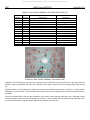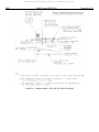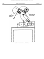
1
Downloaded from SAE International by Yoshihiro Ozawa, Wednesday, January 14, 2015 SURFACE VEHICLE RECOMMENDED AEROSPACE PRACTICE J2860 SEP2012 Issued 2012-09 Superseding EA-26 OCT2003 User's Manual for the Hybrid III Large Male Test Dummy RATIONALE This Surface Vehicle Report describes the assembly/disassembly and certification procedures for the Hybrid III Large Male Test Dummy. Storage and handling, measurement procedures for external dimensions, clothing specifications and part numbers are additions to this Surface Vehicle Report. TABLE OF CONTENTS 1. SCOPE .......................................................................................................................................................... 8 2. 2.1 2.2 REFERENCES .............................................................................................................................................. 8 Applicable Documents .................................................................................................................................. 8 Related Publications ...................................................................................................................................... 8 3. 3.1 3.2 3.3 3.4 3.5 ASSEMBLY/DISASSEMBLY ......................................................................................................................... 9 Head/Neck .................................................................................................................................................... 9 Upper Torso ................................................................................................................................................ 16 Lower Torso ................................................................................................................................................ 28 Legs............................................................................................................................................................. 33 Arms ............................................................................................................................................................ 38 4. 4.1 4.2 4.3 4.4 4.5 CERTIFICATION TEST PROCEDURES .................................................................................................... 40 Head Drop Test ........................................................................................................................................... 40 Neck Tests .................................................................................................................................................. 42 Thorax Impact Test ..................................................................................................................................... 47 Knee Impact Test ........................................................................................................................................ 50 Knee Slider Test .......................................................................................................................................... 52 5. 5.1 5.2 5.3 5.4 5.5 5.6 5.7 INSPECTION PROCEDURES AND TESTS............................................................................................... 55 Chest Depth Measurements ....................................................................................................................... 55 External Measurements .............................................................................................................................. 55 External Dimensions ................................................................................................................................... 58 Mass Measurements ................................................................................................................................... 58 Torso Flexion Test ...................................................................................................................................... 59 Foot Test ..................................................................................................................................................... 62 Ankle Motion Test ....................................................................................................................................... 64 6. 6.1 NOTES ........................................................................................................................................................ 68 Marginal Indicia ........................................................................................................................................... 68 APPENDIX A APPENDIX B ACCELEROMETER HANDLING GUIDELINES ......................................................................................... 69 GUIDELINES FOR REPAIRING FLESH .................................................................................................... 71 __________________________________________________________________________________________________________________________________________ SAE Technical Standards Board Rules provide that: “This report is published by SAE to advance the state of technical and engineering sciences. The use of this report is entirely voluntary, and its applicability and suitability for any particular use, including any patent infringement arising therefrom, is the sole responsibility of the user.” SAE reviews each technical report at least every five years at which time it may be revised, reaffirmed, stabilized, or cancelled. SAE invites your written comments and suggestions. Copyright © 2012 SAE International All rights reserved. No part of this publication may be reproduced, stored in a retrieval system or transmitted, in any form or by any means, electronic, mechanical, photocopying, recording, or otherwise, without the prior written permission of SAE. TO PLACE A DOCUMENT ORDER: SAE WEB ADDRESS: Tel: 877-606-7323 (inside USA and Canada) Tel: +1 724-776-4970 (outside USA) Fax: 724-776-0790 Email: [email protected] http://www.sae.org SAE values your input. To provide feedback on this Technical Report, please visit http://www.sae.org/technical/standards/J2860_201209 Downloaded from SAE International by Yoshihiro Ozawa, Wednesday, January 14, 2015 SAE J2860 Issued SEP2012 Page 2 of 74 APPENDIX C APPENDIX D APPENDIX E JOINT ADJUSTMENT PROCEDURES ...................................................................................................... 72 AXIAL INTEGRITY OF THE NECK............................................................................................................. 73 BOLT TORQUE VALUES ........................................................................................................................... 74 FIGURE 1 FIGURE 2 FIGURE 3 FIGURE 4 FIGURE 5 FIGURE 6 FIGURE 7 FIGURE 8 FIGURE 9 FIGURE 10 FIGURE 11 FIGURE 12 FIGURE 13 FIGURE 14 FIGURE 15 FIGURE 16 FIGURE 17 FIGURE 18 FIGURE 19 FIGURE 20 FIGURE 21 FIGURE 22 FIGURE 23 FIGURE 24 FIGURE 25 FIGURE 26 FIGURE 27 FIGURE 28 FIGURE 29 FIGURE 30 FIGURE 31 FIGURE 32 FIGURE 33 FIGURE 34 FIGURE 35 FIGURE 36 FIGURE 37 FIGURE 38 FIGURE 39 FIGURE 40 FIGURE 41 FIGURE 42 FIGURE 43 FIGURE 44 FIGURE 45 FIGURE 46 FIGURE 47 FIGURE 48 FIGURE 49 FIGURE 50 FIGURE 51 FIGURE 52 FIGURE 53 FIGURE 54 FIGURE 55 FIGURE 56 ACCELEROMETER LOCATIONS ................................................................................................................ 7 HEAD, EXPLODED VIEW ............................................................................................................................ 9 NECK ADJUSTMENT SHCS AND WASHER ............................................................................................ 10 UPPER NECK BRACKET AND BIB............................................................................................................ 10 SKULL CAP................................................................................................................................................. 11 NECK TRANSDUCER ................................................................................................................................ 11 NECK COMPRESSION TOOL ................................................................................................................... 11 NECK REMOVAL ........................................................................................................................................ 12 NODDING JOINT ........................................................................................................................................ 12 NODDING BLOCK ORIENTATION ............................................................................................................ 13 NECK TRANSDUCER REMOVAL .............................................................................................................. 13 NECK, EXPLODED VIEW .......................................................................................................................... 15 NODDING JOINT BRACKET REMOVAL ................................................................................................... 16 CLAVICLE LINK, EXPLODED VIEW .......................................................................................................... 17 CLAVICLE AND SHOULDER YOKE, EXPLODED VIEW .......................................................................... 18 CLAVICLE LINK .......................................................................................................................................... 19 ARM REMOVAL .......................................................................................................................................... 19 CLAVICLE LINK BOLT................................................................................................................................ 20 BUMPER STOP .......................................................................................................................................... 20 SHOULDER YOKE ROTATION STOP ....................................................................................................... 21 UPPER ARM STOP .................................................................................................................................... 21 CLAVICLE SHSS ........................................................................................................................................ 21 URETHANE SPRING STOP ....................................................................................................................... 22 CLAVICLE SPACERS ................................................................................................................................. 22 CLAVICLE LOCK NUT ................................................................................................................................ 23 FRONT RIB STIFFENER ............................................................................................................................ 24 CHEST CAVITY, STERNUM SLIDER ........................................................................................................ 24 STERNUM SLIDER AND BIB ..................................................................................................................... 24 RIB AND RIB STIFFENER REMOVAL ....................................................................................................... 25 RIB AND DAMPING MATERIAL ................................................................................................................. 25 THORACIC SPINE ASSEMBLY, EXPLODED ............................................................................................ 26 THORACIC SPINE REMOVAL ................................................................................................................... 27 CHEST POTENTIOMETER ........................................................................................................................ 27 LOWER TORSO, EXPLODED VIEW ......................................................................................................... 29 LEG REMOVAL........................................................................................................................................... 29 LOWER TORSO ASSEMBLY (ABDOMEN NOT SHOWN) ....................................................................... 30 ABDOMEN .................................................................................................................................................. 31 FEMUR REMOVAL ..................................................................................................................................... 31 FEMUR ASSEMBLY ................................................................................................................................... 32 ASIS LOAD CELL REMOVAL ..................................................................................................................... 32 UPPER LEG, EXPLODED VIEW ................................................................................................................ 33 BALL SLIDER ASSEMBLY, EXPLODED VIEW ......................................................................................... 34 LOWER LEG, EXPLODED VIEW ............................................................................................................... 35 ANKLE ASSEMBLY, EXPLODED VIEW .................................................................................................... 36 FEET AND ATTACHMENT BOLT .............................................................................................................. 37 ARM ASSEMBLY, EXPLODED VIEW ........................................................................................................ 39 HEAD DROP TEST SET-UP SPECIFICATIONS ....................................................................................... 41 NECK PENDULUM SPECIFICATIONS ...................................................................................................... 45 NECK EXTENSION TEST SET-UP SPECIFICATIONS ............................................................................. 46 NECK FLEXION TEST SET-UP SPECIFICATIONS .................................................................................. 46 THORAX IMPACT TEST SET-UP SPECIFICATIONS ............................................................................... 49 HYSTERESIS DEFINITION ........................................................................................................................ 50 KNEE IMPACT TEST SET-UP SPECIFICATIONS .................................................................................... 52 KNEE SLIDER TEST SET-UP SPECIFICATION ....................................................................................... 54 CHEST DEPTH MEASUREMENT TOOL ................................................................................................... 55 EXTERNAL DIMENSION MEASUREMENT ............................................................................................... 57 Downloaded from SAE International by Yoshihiro Ozawa, Wednesday, January 14, 2015 SAE J2860 Issued SEP2012 Page 3 of 74 FIGURE 57 FIGURE 58 FIGURE 59 FIGURE 60 FIGURE 61 FIGURE 62 TORSO FLEXION TEST SETUP ................................................................................................................ 61 TORSO FLEXION PULL BRACKET SPECIFICATIONS ............................................................................ 62 COMPRESSION TEST SETUP .................................................................................................................. 63 FOOT TEST SPECIFICATIONS ................................................................................................................. 64 LEG REFERENCE PLANES ....................................................................................................................... 66 ANKLE/FOOT REFERENCE PLANES ....................................................................................................... 67 TABLE 1 TABLE 2 TABLE 3 TABLE 4 TABLE 5 TABLE 6 TABLE 7 TABLE 8 TABLE 9 TABLE 10 TABLE 11 TABLE 12 TABLE 13 TABLE 14 TABLE 15 TABLE 16 TABLE 17 TABLE 18 TABLE 19 TABLE 20 TABLE 21 TABLE 22 TABLE 23 TABLE E1 INSTRUMENTATION.................................................................................................................................... 6 HEAD, EXPLODED VIEW PART LIST ......................................................................................................... 9 NECK EXPLODED VIEW PART LIST ........................................................................................................ 14 CLAVICLE LINK EXPLODED VIEW PARTS LIST ..................................................................................... 17 CLAVICLE AND SHOULDER YOKE EXPLODED VIEW PART LIST ........................................................ 18 SPINE BOX EXPLODED PART LIST ......................................................................................................... 26 LOWER TORSO EXPLODED PART LIST ................................................................................................. 28 UPPER LEG EXPLODED VIEW PART LIST ............................................................................................. 33 BALL SLIDER ASSEMBLY, EXPLODED VIEW PART LIST ...................................................................... 34 LOWER LEG, EXPLODED VIEW PART LIST ........................................................................................... 35 ANKLE ASSEMBLY, EXPLODED VIEW PART LIST ................................................................................. 36 FOOT ASSEMBLY, EXPLODED VIEW PART LIST ................................................................................... 37 ARM ASSEMBLY, EXPLODED VIEW PART LIST ..................................................................................... 38 HEAD DROP TEST SPECIFICATIONS...................................................................................................... 41 NECK FLEXION TEST SPECIFICATIONS................................................................................................. 43 NECK EXTENSION TEST SPECIFICATIONS ........................................................................................... 44 THORAX IMPACT TEST SPECIFICATIONS ............................................................................................. 48 KNEE IMPACT TEST SPECIFICATIONS................................................................................................... 51 KNEE SLIDER TEST SPECIFICATIONS ................................................................................................... 53 EXTERNAL MEASUREMENTS .................................................................................................................. 58 SEGMENT MASS ....................................................................................................................................... 59 FOOT TEST SPECIFICATIONS ................................................................................................................. 64 ANKLE MOTION SPECIFICATIONS .......................................................................................................... 68 TORQUE SPECIFICATIONS ...................................................................................................................... 74 INTRODUCTION FOREWORD The Hybrid III Large Male dummy was developed under a grant awarded by the Center for Disease Control (CDC) to the Ohio State University in 1997. A task force of experts from the SAE International Mechanical Human Simulation Subcommittee of the Human Biomechanics and Simulation Standards Committee supported the development activity. The design incorporated the same level of biofidelity and measurement capacity as the Hybrid III mid-size adult male. Therefore, the certification procedures are based on the test procedures that were developed for the Hybrid III mid-size adult male dummy. The basic test fixtures are the same. The Hybrid III Large Male Dummy is based on the characteristic size and weight measurements taken from anthropometry studies of the large adult male. Its impact response requirements for the head, neck, chest, hip, knee and ankle were scaled from the biofidelity requirements of the Hybrid III mid-size male dummy. (See Mertz, H. J., Irwin, A. L., Melvin, J. W., Stalnaker, R. L., Beebe, M. S., “Size, Weight, and Biomechanical Impact Response Requirements for Adult Size Small Female and Large Male Dummies”, SAE #890756, SP-782, 1989.) The Hybrid III Large Male dummy is designed to represent the upper extreme of the United States adult population. Much of the anthropometry and design is a scaled version of the Hybrid III midsize adult male dummy. Downloaded from SAE International by Yoshihiro Ozawa, Wednesday, January 14, 2015 SAE J2860 Issued SEP2012 Page 4 of 74 MANUAL OVERVIEW Appendices Several guidelines and procedures apply to various parts throughout the dummy and are included in the appendices for easier reference. When handling an instrumented dummy, improper techniques can damage instrumentation, particularly accelerometers. Appendix A contains guidelines for safe handling of instrumented dummies. The vinyl flesh of dummies can be damaged, but is often repairable. Appendix B contains instructions for repairing dummy flesh. Procedures for adjusting the joints throughout the dummy are included in Appendix C. The axial integrity of the neck is listed in Appendix D. A bolt torque value chart is Appendix E. SAE Documents In addition to the attached appendices, other SAE publications are particularly useful when working with the Hybrid III dummy. SAE J211-1 provides the most recent guidelines and procedures for dummy instrumentation and filtering. SAE Information Report J1733 illustrates the instrumentation available for the Hybrid III dummy family, along with descriptions of how to apply the positive right-hand rule sign convention. SAE Test Definitions Certification Test Certification tests are specified for dummy responses which could affect dummy measurements that are used by government and safety engineers to assess occupant injury potential. Certification tests are performed by the dummy manufacturer to assure that a new component or assembly meets the SAE specified response requirements. The crash dummy user will periodically perform the certification tests to assure the dummy is maintained at the SAE specified performance levels. Inspection Test Inspection tests are supplemental to the certification tests to insure that a component meets its design intent. They are performed by the dummy manufacturer on new parts. The dummy user may conduct inspection tests when a part is damaged or replaced. Abbreviations ASIS Anterior Superior Iliac Spine LCR Load Cell Replacement Downloaded from SAE International by Yoshihiro Ozawa, Wednesday, January 14, 2015 SAE J2860 Issued SEP2012 Page 5 of 74 The following threaded fastener abbreviations are used in this manual. SHCS Socket Head Cap Screw FHCS Flat Head Cap Screw BHCS Button Head Cap Screw SHSS Socket Head Shoulder Screw SSCP Socket Screw, Cup Point RHMS Round Head Machine Screw CONSTRUCTION The skull and skull cap are both one-piece cast aluminum, with a removable one-piece vinyl head and skull cap skin. The skull cap is removable for access to the head instrumentation. The vinyl skin is tuned to give a human-like response to forehead impacts. The neck has a biofidelic “angle versus moment” response in both dynamic flexion (forward bending) and extension (rearward bending) articulations. A neck cable controls stretching responses, and increases the neck’s durability to high axial tension forces. The two-piece aluminum clavicle and clavicle-link assembly have cast integral scapulae (with a lip along the superiormedial edge) to prevent the neck from interfacing with shoulder belts. Six spring steel ribs with polymer-based damping material approximate the human chest force-deflection response characteristics. The sternum assembly connects to the front of the ribs and incorporates a slider for a chest deflection transducer to measure rib cage deflection relative to the thoracic spine. A curved lumbar spine gives a sitting posture to simulate a person of larger stature in the driving position. The pelvis has a human shape and comes equipped with load cell replacements that can be replaced by transducers that indicate submarining of the pelvis. A knee slider mechanism is used that consists of steel ball sliders with energy absorbing molded rubber mounted on aluminum knees. This allows for displacement of the tibia relative to the femur, simulating ligament response. The leg assemblies are steel structures covered with vinyl. The legs are interchangeable with instrumented versions. Constant friction movable joints are used that need few adjustments and provide consistent articulations. The standard model has a “seated” pelvis construction. A “sit/stand” pelvis version is optional, as are a neck covering for airbag testing, a deformable face for steering wheel rim testing, and a deformable abdomen for lap belt submarining and steering wheel rim evaluations. Downloaded from SAE International by Yoshihiro Ozawa, Wednesday, January 14, 2015 SAE J2860 Issued SEP2012 Page 6 of 74 CLOTHING When used in testing, the dummy should wear snug-fitting cotton knit T-shirt and pants. The neckline should be small enough to prevent contact between a shoulder belt and the dummy’s skin. The pants should end above the dummy’s knee. The T-shirt and pants should each weigh no more than 0.27 kg (0.6 lb). Garments similar to thermal underwear (trimmed to be short-sleeved and above the knee) usually meet these requirements. To improve the quality of high-speed films taken of the dummy during testing (by avoiding excessive glare), the garments are usually dyed to a light pink. A size large shirt (L) and double extra large pants (XXL) are suggested sizes for proper fit and weight. The shoes used with the large male dummy are size 11XW shoe which meets the configuration size, sole, and heel thickness specifications of MILS-13192 change ‘‘P’’ and whose weight is 1.25 ± 0.2 pounds. INSTRUMENTATION When ordering a new dummy, inform the dummy manufacturer of the type and model of accelerometer you intend to use. This will ensure that you obtain the correct accelerometer mounts for the head, chest and pelvis. The following is an instrumentation list currently available for the Hybrid III Large Male dummy. TABLE 1 - INSTRUMENTATION HYBRID III LARGE MALE DUMMY INSTRUMENTATON Location Measurement Head C.G. Acceleration Head Angular Acceleration Head Angular Rate Head-Neck Interface Forces & Moments Head-Neck Interface Forces & Moments Neck-Thorax Interface Forces & Moments Thorax C.G. Acceleration Thoracic Spine Forces & Moments Sternum Acceleration Thoracic Spine (Front) Acceleration Sternum Displacement Lumbar Spine Forces & Moments Pelvis C.G. Acceleration Anterior Superior Iliac Spine Load Femur Forces & Moments Femur Force Knee-Tibia Displacement Knee-Clevis Force Upper Tibia Forces & Moments Lower Tibia Forces & Moments Foot Acceleration Number of Channels 3 9 or 12 3 3 6 6 3 5 3 3 1 3 or 6 3 2 each side 6 each femur 1 each femur 1 each knee 2 each knee 5 each leg 5 each leg 3 each foot Downloaded from SAE International by Yoshihiro Ozawa, Wednesday, January 14, 2015 SAE J2860 Issued SEP2012 Page 7 of 74 FIGURE 1 - ACCELEROMETER LOCATIONS SPECIAL TOOLS The following special tools will allow assembly, disassembly and certification of the Hybrid III large male dummy. For information concerning tool availability, contact the dummy manufacturers. -- Neck compression tool -- Ball hex wrench set -- Lumbar cable nut wrench -- Pelvis angle measurement tool -- Head skin thickness gauge -- Chest depth gauge -- Clavicle washer alignment tool -- Iliac bolt removal tool Downloaded from SAE International by Yoshihiro Ozawa, Wednesday, January 14, 2015 SAE J2860 Issued SEP2012 Page 8 of 74 1. SCOPE This SAE Surface Vehicle Information Report identifies and defines the assembly/disassembly and certification procedures relating to the use of the Hybrid III Large Male Test Dummy. 2. REFERENCES 2.1 Applicable Documents The following publications form a part of this specification to the extent specified herein. Unless otherwise indicated, the latest issue of SAE publications shall apply. 2.1.1 SAE Publications Available from SAE International, 400 Commonwealth Drive, Warrendale, PA 15096-0001, Tel: 877-606-7323 (inside USA and Canada) or 724-776-4970 (outside USA), www.sae.org. Mertz, H. J., Irwin, A. L., Melvin, J. W., Stalnaker, R. L., Beebe, M. S., “Size, Weight, and Biomechanical Impact Response Requirements for Adult Size Small Female and Large Male Dummies”, SAE #890756, SP-782, 1989. SAE J211-1 Instrumentation for Impact Test - Part 1 - Electronic Instrumentation SAE J1733 Sign Convention for Vehicle Crash Testing SAE J2517 Hybrid III Family Chest Potentiometer Calibration Procedure SAE J2859 SAE Hybrid III Large Male Drawing Package 2.2 Related Publications The following publications are provided for information purposes only and are not a required part of this SAE Technical Report. 2.2.1 SAE Publications Available from SAE International, 400 Commonwealth Drive, Warrendale, PA 15096-0001, Tel: 877-606-7323 (inside USA and Canada) or 724-776-4970 (outside USA), www.sae.org. SAE J2570 Performance Specifications for Anthropomorphic Test Device Transducers Downloaded from SAE International by Yoshihiro Ozawa, Wednesday, January 14, 2015 SAE J2860 Issued SEP2012 Page 9 of 74 3. ASSEMBLY/DISASSEMBLY 3.1 Head/Neck TABLE 2 - HEAD, EXPLODED VIEW PART LIST Item Number 1 2 3 4 5 6 7 8 9 10 11 12 13 14 15 Quantity 1 1 1 4 1 4 4 2 1 2 1 2 4 1 1 Part Number 880995-105 880995-095X 880995-1715 9000224 78051-383X 9000677 9000453 78051-253 78051-339 9000452 SA572-S80 9000531 78051-94 78051-220 78051-229 Description Head skin Machined Skull Accelerometer mount SHCS 10-24 x 5/8 Upper neck load cell replacement (Upper neck load cell not shown) Washer, Flat .2510 x .38 OD x .06 THR SHCS ¼-28 x ¾ Washer, Nodding Joint Pivot pin, Neck Transducer SSCP 8-32 x ¼ Accelerometer cube SHCS 2-56 x 5/8 SHCS ¼-20 x 5/8 Machined skull cap Skull cap skin FIGURE 2 - HEAD, EXPLODED VIEW Downloaded from SAE International by Yoshihiro Ozawa, Wednesday, January 14, 2015 SAE 3.1.1 J2860 Issued SEP2012 Page 10 of 74 Chest Jacket Remove the chest jacket to permit easier access to the base of the neck bracket. For easy removal of the jacket, remove the arms first (Figure 17). Remove the SHCS (Figure 3) that holds the upper neck bracket to the lower portion of the neck bracket and permits adjustment of the neck angle. Check the condition of the curved steel washer and note how it fits on the neck bracket. FIGURE 3 - NECK ADJUSTMENT SHCS AND WASHER Tilt the head and neck forward and remove the neck cable nut and four SHCS that hold the upper neck bracket to the base of the neck (Figure 4). Check for the presence of four steel washers between these four SHCS and upper neck bracket upon reassembly. If they are missing, replace them upon reassembly. The neck and head assembly is now disconnected from the plastic sternum-to-rib cage bib assembly. FIGURE 4 - UPPER NECK BRACKET AND BIB Downloaded from SAE International by Yoshihiro Ozawa, Wednesday, January 14, 2015 SAE J2860 Issued SEP2012 Page 11 of 74 Remove four SHCS from the rear skull cap once the head and neck have been separated from the dummy (Figure 5). FIGURE 5 - SKULL CAP For the six-channel neck transducer or its structural replacement, loosen two SSCP that secure the head-to-neck pivot pin (Figure 6). FIGURE 6 - NECK TRANSDUCER There are several neck compression tools in existence. Figure 7 is a representative model of such a tool available to assist in the separation of the head and neck. FIGURE 7 - NECK COMPRESSION TOOL Downloaded from SAE International by Yoshihiro Ozawa, Wednesday, January 14, 2015 SAE J2860 Issued SEP2012 Page 12 of 74 For this design, the compression tool is mounted to the head by fastening the flat plate to the back of the skull. Then, slip the round end of the tool over the cable and turn the knob until the neck begins to compress (Figure 8). FIGURE 8 - NECK REMOVAL Slowly increase the compression on the neck until the pivot pin can be pushed or lightly tapped out with a minimal amount of effort. Reduce the compression on the head and neck, allowing the head and neck to separate at the nodding joint (Figure 9). Two brass washers and the two rubber nodding blocks may fall out in the disassembly process. To assemble the head and neck, be sure the nodding blocks, washers and nodding joint are in place before compressing the neck using the compression tool. Once compressed, slide the pivot pin into place while orienting the flats on the pin toward the set screw locations. Tighten the set screws to finish the assembly. With the head and neck disassembled, inspect the neck cable for imperfections. No evidence of the cable pulling through the end fittings should exist. Examine the machined metal parts and compare the rubber sections of the neck against the drawing. FIGURE 9 - NODDING JOINT Downloaded from SAE International by Yoshihiro Ozawa, Wednesday, January 14, 2015 SAE J2860 Issued SEP2012 Page 13 of 74 Once separated, check the condition of the two rubber neck nodding blocks on the top of the nodding joint. The 90 degree surfaces of the nodding blocks fit opposite, rather than inside, the 90 degree grooves of the head-to-neck adaptor bracket (Figure 10). FIGURE 10 - NODDING BLOCK ORIENTATION Upon re-assembly, assemble the two sections of the neck bracket with the adjustment set to 0 degree and measure the bracket angle. The lug on the nodding joint must fit very tightly in the slot in the bottom of the neck load cell. The tightness is controlled by a brass washer on each side of the yoke. These washers must be lapped to produce a 0.000 to 0.025 mm (0.000 to 0.001 in) interference fit at assembly. Because the inside diameter of these washers is also critical, validate this dimension against the drawing. 3.1.2 Head Remove the four SHCS on the underside of the skull (Figure 11). A steel washer under each of the cap screws helps to protect the aluminum from being galled by the steel screws (Figure 2, Item 6). These are special washers and must be used under the load cell attachment bolts. Larger washers will interfere with load cell operation. After the screws have been removed, the transducer can then be removed by lifting it upward and out the back of the skull opening. The transducer may have to be turned slightly sideways to do this. The accelerometer mount and cube are shown as reference (Figure 2, Item 3 & 11). Accelerometer mounts and cubes can differ depending on the accelerometers being used and the manufacturer of the mount. FIGURE 11 - NECK TRANSDUCER REMOVAL Downloaded from SAE International by Yoshihiro Ozawa, Wednesday, January 14, 2015 SAE J2860 Issued SEP2012 Page 14 of 74 To remove the flesh from the skull, hold the skull by the back of the skull opening. Peel the skin forward starting at the top rear of the skull and skin assembly. This should allow the skin to pull away from the skull and then slide off the chin area. To remove the cap skin from the machined skullcap, follow a similar procedure. The skin should be inspected for nicks, tears or other damage that may be present after testing. If damaged, the skin should be repaired or replaced (see Special Care and Maintenance). Inspect the skull for smoothness and freedom from flat spots and pits. Examine the bond of the skull ballast. If the ballast must be reinstalled or changed, see drawing for instructions. 3.1.3 Neck Figure 12 is an exploded view of the neck assembly. Table 3 gives a general description of each item in Figure 12. TABLE 3 - NECK EXPLODED VIEW PART LIST Item Number 1 2 3 4 5 6 7 8 9 10 11 12 13 14 15 16 17 18 Quantity 2 1 1 1 1 1 1 4 4 1 1 1 1 1 1 1 2 4 Part Number 78051-253 78051-339 180-2004 880995-205 9000018 9001260 180-2005 9008001 9000498 78051-305 9000021 880995-1270 880995-201 880995-1260 880995-203 78051-297 78051-351 9000124 Part Description Brass Washers Condyle Pin Upper Neck Bushing Cable Nut, Hex Jam 1/2-20 Washer Lower Neck Bushing Washer Screw, SHCS 1/4-20 x 7/8 Neck Adjustment Washer Screw, SHCS 3/8-16 x 1 Upper Neck Adjustment Bracket Lower Neck Spacer Neck Molded Assembly Upper Neck Spacer Nodding Joint Neck Assembly Nodding Block Screw, FHCS 1/4-20 x 7/8 Downloaded from SAE International by Yoshihiro Ozawa, Wednesday, January 14, 2015 SAE J2860 Issued SEP2012 FIGURE 12 - NECK, EXPLODED VIEW Page 15 of 74 Downloaded from SAE International by Yoshihiro Ozawa, Wednesday, January 14, 2015 SAE J2860 Issued SEP2012 Page 16 of 74 Remove the nodding blocks and set aside. The pivot pin, nodding joint washers, SHCS and curved steel washer, as well as the neck bushings, washer and nut have been previously removed (see Head/Neck disassembly). Remove four FHCS from the top of the nodding joint bracket (Figure 13). FIGURE 13 - NODDING JOINT BRACKET REMOVAL Upon removal of the four FHCS, the neck disassembly is complete (Figure 12). Note that the nodding joint bracket is separated from the upper neck by an upper neck spacer plate. The lower neck adjustment bracket is separated from the lower neck plate by a lower neck spacer plate. They are distinguishable by their hole patterns. The upper neck spacer plate has a symmetrical hole pattern that matches the nodding joint bracket while the lower neck spacer plate has an offset hole pattern that matches the lower neck adjustment bracket to ensure proper assembly. 3.1.4 Head/Neck Special Care and Maintenance Check for tears or breaks in the neck. Check the head skin for tears or cracks. Repair the head skin as outlined in Appendix B. Damage to the head skin in the forehead region should not be repaired, as this will affect test results. Replace. Check the skull casting for dents or cracks. Replace if damaged. Check the nodding blocks for wear and deformation. Noise and improper loading of the nodding joint will occur with damaged blocks. Check the axial integrity of the neck. (see Appendix D) The neck cable should be torqued to 1.36 Nm 0.23 Nm (12.0 in-lbf 2.2 in-lbf) 3.2 3.2.1 Upper Torso Shoulder/Clavicles Figures 14 and 15 show the clavicle and shoulder exploded views. The corresponding table is the general part description that correlates with the adjacent item number. Downloaded from SAE International by Yoshihiro Ozawa, Wednesday, January 14, 2015 SAE J2860 Issued SEP2012 Page 17 of 74 TABLE 4 - CLAVICLE LINK EXPLODED VIEW PARTS LIST Item Number 1 2 3 4 5 6 7 8 9 Quantity 1 1 2 1 1 1 1 2 1 Part Number 9006001 880995-358 78051-236 880995-334 (left), 880995-335 (right) 78051-243 9000043 880995-338 880995-339 880995-336 (left), 880995-337 (right) Part Description SHSS Clavicle Link Pivot Bushing Clavicle Link Pivot Washer Clavicle Link Washer SHSS ½ x 1 Clavicle Spring Stop Clavicle Spacer Clavicle FIGURE 14 - CLAVICLE LINK, EXPLODED VIEW Downloaded from SAE International by Yoshihiro Ozawa, Wednesday, January 14, 2015 SAE J2860 Issued SEP2012 Page 18 of 74 TABLE 5 - CLAVICLE AND SHOULDER YOKE EXPLODED VIEW PART LIST Item Number 1 2 3 4 5 6 7 8 9 10 11 12 13 14 15 16 17 Quantity 1 1 1 2 1 1 1 1 1 1 1 1 1 1 1 1 1 Part Number 78051-250 78051-249 78051-248 9000047 880995-346 78051-245 78051-202 880995-351 880995-709 880995-708 880995-711 9000055 880995-343 880995-348 880995-349 880995-336 (left), 880995-337 (right) 9000800 Part Description Washer, Shoulder Yoke Retaining Washer, Spring Washer, Steel Shoulder Yoke SHCS Steel Stop Shoulder Stop Assembly Nut, Elbow Pivot Washer, Spring Bushing, Upper Arm and Elbow Pivot Washer, Upper arm and Elbow Pivot Washer SHSS Shoulder Yoke Assembly Bushing, Shoulder Yoke Pivot Washer, Yoke Pivot Clavicle Locknut, Thin FIGURE 15 - CLAVICLE AND SHOULDER YOKE, EXPLODED VIEW The right and left shoulder-clavicle and link assemblies consist of three main sections; the clavicle, clavicle link and shoulder yoke, which bolt to each other and then to the thoracic spine. These three sections permit arm rotation, up-down motion at the shoulder, forward-rear excursion (hunching), and up-down motion of the entire shoulder-clavicle unit. See Figure 16 for the assembled view of the shoulder clavicle link. Downloaded from SAE International by Yoshihiro Ozawa, Wednesday, January 14, 2015 SAE J2860 Issued SEP2012 Page 19 of 74 FIGURE 16 - CLAVICLE LINK To begin disassembling the clavicles, it is optional to first remove each arm at the shoulder yoke by unscrewing the SHSS (Figure 17). If necessary, clean the clavicle bushing and washers with isopropyl alcohol. Never lubricate any of the plastic bushings. FIGURE 17 - ARM REMOVAL Detach the shoulder-clavicle unit from the thoracic spine assembly by reaching through a hole in the plastic chest "bib" and removing the SHSS at the extreme top of the thoracic spine (Figure 18). Pull the clavicle unit straight up. Check for the urethane washer at the rear of the cavity in the thoracic spine and for two clavicle washers isolating the clavicle from the spine. Make sure the pivot nut slides out freely. A clavicle bushing should also be present in the hole through the clavicle link. Downloaded from SAE International by Yoshihiro Ozawa, Wednesday, January 14, 2015 SAE J2860 Issued SEP2012 Page 20 of 74 FIGURE 18 - CLAVICLE LINK BOLT At this time, use a pair of needle nose pliers to remove the rubber bumper stop from the Thoracic Spine (Figure 19). Inspect the shoulder yoke for damage. The stop should be free from tears or permanent deformation, and should be symmetrical in cross section. FIGURE 19 - BUMPER STOP The shoulder yoke assembly contains three stops. One is a steel stop that contacts a rubber rear stop when the arm is extended (Figure 20). There are four holes available for positioning the steel stop on the shoulder yoke. The steel stop should be positioned in the two mounting holes furthest from the rear stop, as shown in Figure 20. The third stop is the rubber shoulder pivot stop that prevents excessive arm abduction (Figure 21). Upon disassembly, all stops should be inspected for damage. Downloaded from SAE International by Yoshihiro Ozawa, Wednesday, January 14, 2015 SAE J2860 Issued SEP2012 Page 21 of 74 FIGURE 20 - SHOULDER YOKE ROTATION STOP FIGURE 21 - UPPER ARM STOP Remove the SHSS (Figure 22) and its steel washer that holds the two aluminum sections of the clavicle and its link together. FIGURE 22 - CLAVICLE SHSS A urethane spring "stop" should be located at the back of the cavity in the inner clavicle link (Figure 23). Downloaded from SAE International by Yoshihiro Ozawa, Wednesday, January 14, 2015 SAE J2860 Issued SEP2012 Page 22 of 74 FIGURE 23 - URETHANE SPRING STOP Top and bottom thin clavicle spacers (Figure 24) should isolate the two sections. FIGURE 24 - CLAVICLE SPACERS The shoulder yoke connects the arm to the clavicle. To remove the shoulder yoke, use an open wrench or equivalent tool to remove the lock nut (Figure 25). Once the nut is removed, the shoulder yoke will slide out and the disassembly is complete. Check for a steel stop on the rim of the shoulder yoke, held by two SHCS (Figure 20). The stop can be installed in two positions: one for the right side and the other for the left. Inspect clavicle aluminum parts for porosity and cracks. This will complete the disassembly of the clavicle from the clavicle link. Before assembly, ensure the spring stop is in position. Use a clamp or compression tool to squeeze the clavicle and clavicle link in order to compress the urethane spring stop until insertion of the clavicle SHSS is possible. Downloaded from SAE International by Yoshihiro Ozawa, Wednesday, January 14, 2015 SAE J2860 Issued SEP2012 Page 23 of 74 FIGURE 25 - CLAVICLE LOCK NUT 3.2.2 Shoulder/Clavicles Assembly Notes When mounting the lower neck bracket to the top of the spine, ensure that the cap screws have metal washers to protect the aluminum. Assemble the shoulder yokes, clavicles, and clavicle links. The long flat clavicle spacers are easily damaged during assembly. An alignment tool will assist in this operation. Assemble the clavicles to the thoracic spine assembly. The flat spots on the flat clavicle washers are on the side nearest the centerline of the spine. 3.2.3 Ribs and Sternum Remove the twelve BHCS holding the front of the ribs to the bib (Figure 26). Inspect the thin steel strips under the bolt heads for cracks. Check the thicker, slightly angled strips behind the rib ends for cracks. Note the way the strips fit the chest. The bend is not symmetrical; the upper portion is shorter than the lower. Allow the chest displacement slider arm to slide out the bottom of the sternum slider slot. Check that the open end of the sternum nut plate is at the bottom (Figure 27). Remove the twelve BHCS screws holding the sternum slider assembly to the bib (Figure 28). Examine the slider for damage and ensure that the slider ball moves freely in its track. Inspect the aluminum plate to which the slider assembly bolts. Inspect the bib for cracks, tears and imperfections. Compare the shape to the drawing. Clean all parts with isopropyl alcohol or an equivalent. Detach the six ribs and their rear rib supports by removing the twelve BHCS screws at the rear of the thoracic spine assembly (Figure 29). Carefully examine each rib and the rib damping material for cracks. Check for gaps or other failures of the epoxy bond between the rib damping material and the rib metal (Figure 30). When reassembling, make sure the rib supports are not bent or damaged and are mounted the correct way. The tapered side of the stiffener should be oriented toward the ribs. Downloaded from SAE International by Yoshihiro Ozawa, Wednesday, January 14, 2015 SAE J2860 Issued SEP2012 FIGURE 26 - FRONT RIB STIFFENER FIGURE 27 - CHEST CAVITY, STERNUM SLIDER FIGURE 28 - STERNUM SLIDER AND BIB Page 24 of 74 Downloaded from SAE International by Yoshihiro Ozawa, Wednesday, January 14, 2015 SAE J2860 Issued SEP2012 Page 25 of 74 FIGURE 29 - RIB AND RIB STIFFENER REMOVAL FIGURE 30 - RIB AND DAMPING MATERIAL After assembling the ribs, or when checking rib condition, use the special tool (V00278) to check for correct chest depth (Refer to Chest Depth Measurements in the Inspection Procedures and Tests section). 3.2.4 Thoracic Spine Figure 31 represents the exploded view of the thoracic spine. Table 6 is a list of general part descriptions identified in Figure 31. Downloaded from SAE International by Yoshihiro Ozawa, Wednesday, January 14, 2015 SAE J2860 Issued SEP2012 Page 26 of 74 TABLE 6 - SPINE BOX EXPLODED PART LIST Item Number 1 2 3 4 5 6 7 8 9 10 11 12 13 14 15 16 17 18 19 20 21 Quantity 1 1 1 4 1 6 2 1 4 2 4 4 1 4 1 4 1 6 4 2 1 Part Number 9000407 3000051 880995-324 9000005 880995-1022 9000528 880995-1021 880995-1000 78051-9 880995-1024-2 (L), 880995-1025-2 (R) 9000009 9000022 78051-303 900433 880995-329 9000540 880995-328 900476 9000559 78051-85 880995-325 Description BHCS ½-20 x ½ Washer Chest Deflection Transducer Assembly SHCS ¼ - 20 x 5/8 Upper Accelerometer Mount SHCS 4-40 x ¼ Lower/Mid Accelerometer Mount Spine Box Assembly Rubber Sternum Stop Upper Rib Guide (L and R) SHCS ¼ - 20 x ¾ Washer Lower Neck Bracket SHCS 5/16 – 24 x 7/8 CG Accelerometer Mount SHCS 8-32 x 3/8 Load Cell Structural Replacement SHCS 5/16 – 18 x 7/8 SHCS 5/16-18 x ¾ Rubber Bumpers Torso flexion stop Spine Mounting Assembly FIGURE 31 - THORACIC SPINE ASSEMBLY, EXPLODED Remove the four SHCS that attach the lumbar spine to the thoracic spine assembly and lift off the thoracic spine (Figure 32). Next, remove the six SHCS from the side of the spine box and slide the thoracic insert out of the thoracic spine cavity. The insert holds the chest accelerometer adapter assembly and chest displacement pot assembly to the bottom of the thoracic spine. Slide the assembly out of the bottom of the thoracic spine. Downloaded from SAE International by Yoshihiro Ozawa, Wednesday, January 14, 2015 SAE J2860 Issued SEP2012 Page 27 of 74 FIGURE 32 - THORACIC SPINE REMOVAL Install the accelerometer block package and make sure no interference with the accelerometers occurs. Check the two larger rubber bumpers protecting the chest displacement pot for damage (Figure 33). To remove the rubber bumpers, remove the two SHCS per bumper from the back side of the spine mounting assembly. Carefully remove the chest deflection transducer assembly by removing the BHCS and washer from the bearing. The assembly should easily push out. Check the bearing for smooth operation. FIGURE 33 - CHEST POTENTIOMETER To remove the thoracic load cell or simulator, remove the four SHCS from the bottom of the spine mounting assembly. Four SHCS on the top of the thoracic load cell will allow for the removal of the T4 accelerometer mount (Figure 31). The thoracic spine will have four rubber bumpers fixed to the front of the spine box to prevent metal-to-metal contact between the ribs and thoracic spine at max deflection of the ribs. Inspect the bumpers for tears and ensure that they are fixed tightly to the spine box. Replace any damaged bumpers and refasten the bumpers if they begin to tear away from the spine box. (Figure 31) The bumpers also prevent contact between the potentiometer arm and the accelerometers mounted on the three accelerometer mounts on the front of the thoracic spine. The bottom two accelerometer mounts are the same. The top accelerometer mount is distinguishable by a notch that aligns with a roll pin to prevent misorientation during assembly. The accelerometer mounts can be removed by removing the two SHCS from the front face of the thoracic spine. (Figure 31) Downloaded from SAE International by Yoshihiro Ozawa, Wednesday, January 14, 2015 SAE J2860 Issued SEP2012 Page 28 of 74 The lower neck adjustment bracket can be disassembled from the thoracic spine by removing four SHCS and washers from the top of the spine box. Two rib guides mount to the side of the spine box and can be removed by removing two SHCS from each side of the spine box (Figure 31). Inspect the Teflon sheets on the underside of the rib guides for damage. Replace if necessary. 3.2.5 Upper Torso Assembly Notes Attach the ribs and rear rib supports to the thoracic spine assembly. Do not tighten the screws. Attach the bib to the TM ribs using the rib stiffeners. Install the aluminum sternum to the inside surface of the bib and attach the Delrin track. TM Ensure that the chest displacement rod ball engages the Delrin track properly (Figure 27). Check the spacing and alignment of the ribs and then tighten the screws. A 3/8 diameter rod can be used as a spacer control for the space between the ribs. 3.2.6 Upper Torso Special Care and Maintenance Check for rib deformation using the chest depth gauge described in Inspection Procedures and Test section. Check the ribs and rib damping material for warping or cracks. Replace damaged ribs and re-certify. Sternum stops should be periodically checked for looseness. If they become loose, they can be glued back into place using an instant adhesive. Check the shoulder castings for compression damage from assembly. Replace damaged castings. Check the rubber shoulder stop for damage and replace as necessary. 3.3 Lower Torso Figure 34 represents the exploded view of the lower torso. Table 7 is a list of general part descriptions identified in Figure 34. TABLE 7 - LOWER TORSO EXPLODED PART LIST Item Number 1 2 3 4 5 6 7 8 9 10 11 12 13 14 15 16 17 18 19 20 21 22 Quantity 4 2 2 1 4 1 4 1 2 1 1 6 2 1 2 2 2 2 2 2 2 3 1 Part Number 9000345 98051-498-1 (Left), 98051-498-2 (Right) 880995-1410 (L), 880995-1411 (R) 78051-13 9000624 9000059 9000348 880995-1445 9000063 78051-54 880995-1430 9000009 880995-1437 (L), 880995-1438 (R) 78051-53 78051-69 880995-1443 9000018 9000018 880995-1444 9000059 9000080 9000005 880995-1416 Description BHCS 8-32 Femur Bumper Femur Assembly (L and R) Cover, Pelvic Cavity SHCS 10-24 x 1/2 SHCS 3/8-16 x ¾ SHCS 5/16-24 1-1/2 Molded Lumbar Spine SHSS 5/8 x 1 3/4 Accelerometer Mount Molded Pelvis SHCS ¼-20 x ¾ ASIS Load Cell Replacement (L and R) Bracket Assembly Lumbar Cable Lower Lumbar Bushing Hex Jam Nut ½-20 Hex Nut ½-20 Upper Lumbar Bushing SHCS 3/8-16 x ¾ SHCS 3/8-16 x ¾ SHCS ¼-20 x 5/8 Abdomen (not shown) Downloaded from SAE International by Yoshihiro Ozawa, Wednesday, January 14, 2015 SAE J2860 Issued SEP2012 Page 29 of 74 FIGURE 34 - LOWER TORSO, EXPLODED VIEW 3.3.1 Lumbar Spine The lumbar spine is more easily accessed if the legs are detached. Remove the SHSS (one per leg) holding the rear of the upper leg to the brass femur. These bolts are located through holes in the flesh at the side and front of the pelvis (Figure 35). Detach the leg assemblies. This will separate and isolate the lower torso. FIGURE 35 - LEG REMOVAL Downloaded from SAE International by Yoshihiro Ozawa, Wednesday, January 14, 2015 SAE J2860 Issued SEP2012 Page 30 of 74 FIGURE 36 - LOWER TORSO ASSEMBLY (ABDOMEN NOT SHOWN) Remove the four SHCS holding the pelvic instrument cavity cover in the rear of the molded pelvis. Once the cover is removed, remove the accelerometer block by removing one SHCS. Separate the lumbar spine and its lumbar-to-pelvic adaptor from the pelvis by removing two SHCS from the front of the adaptor and two SHCS through the pelvic instrumentation cavity (Figure 34). Separate the lumbar spine from the adaptor by removing three SHCS from the bottom of the lumbar adaptor. Check the upper and lower surfaces of the lumbar adaptor (Figure 34). The lower surface must be flat and smooth. The upper surface for mounting the lumbar spine must be flat and smooth and have two hemispherical clearance depressions for the ends of the lumbar cables. Detach the two lumbar cables by removing the two hex and jam nuts on the top of each cable and pulling the cables through the spine (Figure 34). These cables are not interchangeable with the neck cable. Check the top and bottom end plates for flatness and for complete adhesion to the rubber. Make sure sufficient clearance between the swaged balls and the hemispherical seats exists. Each cable will have an upper and lower lumbar bushing. Check the bushing for damage. Clean with a chlorinated solvent if necessary. These bushings are not interchangeable with the neck bushings. 3.3.2 Abdomen Examine the abdominal insert (Figure 37) for skin-to-foam separation, for tears and/or cuts in the vinyl skin, and for air tightness. When compressed, no air should escape. Downloaded from SAE International by Yoshihiro Ozawa, Wednesday, January 14, 2015 SAE J2860 Issued SEP2012 Page 31 of 74 FIGURE 37 - ABDOMEN 3.3.3 Pelvis and Upper Femurs Remove the femur assembly shown in Figure 38 from each side of the pelvis by unscrewing three SHCS per side. Access is gained through the three 1/2 inch diameter holes in each side of the pelvic flesh (Figure 38). First remove the two rear screws and then rotate the femur assembly towards the pelvic center to allow access to the third screw. A tool made to fit in place of the upper leg bone will simplify this task. When removing the femurs, be careful not to tear the urethane bumpers on the top of each femur. A small amount of talcum powder can be used on the bumpers to reduce friction. FIGURE 38 - FEMUR REMOVAL Downloaded from SAE International by Yoshihiro Ozawa, Wednesday, January 14, 2015 SAE J2860 Issued SEP2012 Page 32 of 74 Remove the two BHCS holding the bumpers in place (Figure 39). Inspect the bumpers for tears or cracks and replace if necessary. The bumper is designed to prevent metal-to-metal contact between the femur and the flange/screws that hold the femur, when the femur is rotated towards the pelvis. This holds true when the femur is parallel to the midsagittal plane, as well as 7 degrees inboard and outboard of this plane. Check the femur sockets and femur ball for galling. Confirm that the nylon-tipped femur friction adjusting screws are not damaged (see Figure 39). FIGURE 39 - FEMUR ASSEMBLY The pelvic bone houses two ASIS load cells or simulators. To disassemble from the pelvis, remove four SHCS from the access holes in the rear of the pelvis (Figure 40). FIGURE 40 - ASIS LOAD CELL REMOVAL Examine the pelvis for flesh tears and/or cuts, and the skin for foam separation. If the pelvis cavity for the femur shows signs of deterioration such as these, it will affect the pelvis range of motion and the pelvis should be remolded. 3.3.4 Lower Torso Assembly Notes Torque the lumbar cables to 1.13 to 1.40 Nm (10.0 to 12.4 in-lbf). Install the lumbar adaptor assembly (with the thorax weight and transducers) into the bottom of the thoracic spine. Install the thoracic spine, with adaptor assembly, to the lumbar spine. Downloaded from SAE International by Yoshihiro Ozawa, Wednesday, January 14, 2015 SAE 3.3.5 J2860 Issued SEP2012 Page 33 of 74 Lower Torso Special Care and Maintenance Do not leave the lumbar spine cable torqued when storing the dummy. This will cause permanent deformation of the spine. Check for cracks in the lumbar spine rubber. Check for tears in the pelvis vinyl. Check for chipped, cracked or broken metal pieces or stripped screws and threads. 3.4 3.4.1 Legs Upper Legs and Knees Figure 41 represents the exploded view of the upper leg. Table 8 lists the general part descriptions identified in Figure 41. Figure 42 represents the exploded view of the ball slider knee assembly. Table 9 lists the general part descriptions identified in Figure 42. TABLE 8 - UPPER LEG EXPLODED VIEW PART LIST Item Number 1 2 3 4 5 6 7 Quantity 1 1 1 2 1 1 1 Part Number 880995-1527 880995-508 880995-502 9000066 78051-319 880995-1510 880995-511 Description Upper Leg Flesh Knee Flesh Upper Leg Weldment SHCS 3/8-16 x 2 FEMUR LOAD CELL REPLACEMENT Knee Cap Knee Insert FIGURE 41 - UPPER LEG, EXPLODED VIEW Downloaded from SAE International by Yoshihiro Ozawa, Wednesday, January 14, 2015 SAE J2860 Issued SEP2012 Page 34 of 74 TABLE 9 - BALL SLIDER ASSEMBLY, EXPLODED VIEW PART LIST Item Number 1 2 3 4 5 6 7 8 9 10 11 12 13 14 15 Quantity 1 2 1 1 1 1 1 1 2 1 1 1 1 1 1 Part Number 79051-32 9005045 880995-1645 9006038 880995-1636 880995-1633 880995-1650-2 (L), 880995-1650-2 (R) 880995-1646 9005078 880995-1631-1 (L), 880995-1631-2 (R) SA572-S90 880995-1632 9006035 79051-33 880995-1637 Description Washer BHCS FHCS 2-56 x 3/16 Rubber Stop SHSS .187 Dia. X .25 Ball Stop Travel Stop String Pot Holder Assembly Rubber Stop BHCS SHCS 8-32 x 3/8 Inboard Slider Assembly String Potentiometer Outboard Slider SHSS 3/8 x ½ Compression Washer Knee Stop Pin FIGURE 42 - BALL SLIDER ASSEMBLY, EXPLODED VIEW Separate the knee and upper leg sections by removing the two SHCS that secure the load cell or the femur load cell simulator, upper leg weldment and knee cap. Detach the lower leg from the knee cap by removing eight FHCS (Figure 43). Inspect the knee skin and rubber knee insert by first removing the machined knee (shown in Figure 41). Examine these flesh parts for cuts and tears. Clean the inside and outside of the insert and adjoining knee skin with isopropyl alcohol or equivalent. A pair of six-channel femur load cells are available for use in place of the single-axis femur load cells. Either type of load cell directly replaces the femur load cell simulator in each leg. The six-channel load cells measure axial and shear loads, and moment in three axes, while the single-axis load cells measure axial load only. Downloaded from SAE International by Yoshihiro Ozawa, Wednesday, January 14, 2015 SAE 3.4.2 J2860 Issued SEP2012 Page 35 of 74 Lower Legs and Ankle Figure 43 represents the exploded view of the lower leg. Table 10 lists the general part descriptions identified in Figure 43. Figure 44 shows the exploded view of the ankle assembly. Table 11 lists the general part descriptions identified in Figure 44. TABLE 10 - LOWER LEG, EXPLODED VIEW PART LIST Item Number 1 2 3 4 5 6 7 Part Number Quantity 1 1 1 1 8 4 1 880995-1614 B-1889 A-1886 880995-622 900313 9000115 880995-605 Description Lower Leg Flesh Ankle Assembly Modified SHSS Lower Leg Bone FHCS ¼-28 x 3/8 SHCS ¼-28 x ½ Knee Clevis FIGURE 43 - LOWER LEG, EXPLODED VIEW Downloaded from SAE International by Yoshihiro Ozawa, Wednesday, January 14, 2015 SAE J2860 Issued SEP2012 Page 36 of 74 TABLE 11 - ANKLE ASSEMBLY, EXPLODED VIEW PART LIST Item Number 1 2 3 4 5 6 7 8 9 10 11 Quantity 4 1 1 1 1 2 2 1 1 1 1 Part Number 9000076 78051-610 A-1590 A-1888 A-1897-1 A-1897-2 9000076 C-1885 C-1884 A-1896 A-1672 Description BHCS Ankle Bumper Ankle Shaft Ankle Friction Pad SSCP 5/16-18 x 3/8 SSCP 10-32 x 1/4 BHCS 8-32 x ½ Ankle, Lower Shell Ankle, Upper Shell Dowel Pin 3/16 x 1/2 Stop Pin Retainer FIGURE 44 - ANKLE ASSEMBLY, EXPLODED VIEW Separate the 45 degree foot and ball joint ankle assembly by removing the modified SHSS at the ankle-lower leg intersection (Figure 43, item 3). Figure 44 is the exploded view of the ankle. The ankle assembly and foot can be separated by removing the modified SHSS from the ankle shaft (Figure 45, item 1). Remove the four BHCS from the ankle bumper. This will remove the bumper and expose the lower ankle shell. Two SSCP will be inset to hold in the pin retainer. Two BHCS will hold the lower shell to the upper shell. Remove the two BHCS and SSCP to remove the ankle shaft. The pin retainer and dowel pin can now be removed easily from the assembly. A single SSCP and Delrin friction pad can be found opposite the pin and pin retainer on the ankle shell. When assembled, the SSCP can be tightened onto the friction pad. This will push against the ball of the ankle shaft and control the movement of the ankle joint. Remove the heel insert and inspect for deterioration. Inspect the flesh for tears or damage. Make sure that the ankle bumper is in place and inspect for deterioration. NOTE: The ankle bumper needs to be installed with the thicker rubber section to the front for proper ROM control. Downloaded from SAE International by Yoshihiro Ozawa, Wednesday, January 14, 2015 SAE J2860 Issued SEP2012 Page 37 of 74 TABLE 12 - FOOT ASSEMBLY, EXPLODED VIEW PART LIST Item Number 1 2 Quantity 2 2 Part Number A-1886 880995-1600 (L), 880995-1601 (R) Description Modified SHSS ¼ x ¾ Molded Foot (L and R) FIGURE 45 - FEET AND ATTACHMENT BOLT 3.4.3 Non-Instrumented and Optional Force-Indicating Lower Legs Each Hybrid III Large Male lower leg assembly consists of the ball bearing sliding knee (with an optional potentiometer to measure displacement), a lower leg (either standard or an optional instrumented one), and a 45 degree foot. The knees are attached so the potentiometer mounts inboard in order to provide easier access to the knee adjustment screw when seating the dummy. Separate the lower leg from the machined knee by removing eight FHCS from the clevis. This exposes the knee slider assembly. The slider is detached by removing the SHSS that has a metal and a urethane washer (Figure 42). The two parts of the slider assembly then can be taken off of the machined knee. Disassemble the inboard and outboard stops by removing two BHCS from each stop assembly (Figure 42). Inspect the rubber blocks of the slider and the rubber stops for damage. Inspect the balls in the tracks of the slider to ensure they are in the track securely. If damaged, contact the manufacturer for guidance. The instrumented lower leg option can measure knee (tibia-to-femur) shear, knee clevis axial loads (medial and lateral), upper leg fore-aft and lateral moments plus shear and axial forces, and lower leg fore-aft and lateral moments plus shear. Load cells with five channels to measure various combinations of forces and moments are available for the upper and lower tibias. The standard lower leg (Figure 43) is a welded assembly with a bolt-on knee clevis that can be replaced with an optional instrumented leg. The following section describes the assembly of the optional instrumented lower leg. The upper part of the lower leg consists of the clevis that is bolted to the upper tibia load cell by four SHCS. The optional upper and lower tibia load cells are separated by a heavy wall, aluminum tube that protects the load cell connectors. The upper and lower tibia load cells are each attached to the tube by four modified BHCS. The lower load cell may be rotated 90 degrees if lateral shear and moment are preferred, by using the second slot in the ankle-to-tibia adapter, or this load cell may be purchased with both moment measurements built in. No adjustments are possible except for a friction adjustment at the ankle ball. Downloaded from SAE International by Yoshihiro Ozawa, Wednesday, January 14, 2015 SAE 3.4.4 J2860 Issued SEP2012 Page 38 of 74 Legs Assembly Notes When assembling the knees with the standard, non-instrumented lower legs, the shoulder bolt head is mounted on the outboard side of both knees. The shoulder bolt for the machined knee acts as a control for the motion between the lower leg and knee. 3.4.5 Legs Special Care and Maintenance Check the leg flesh for rips and tears. Repair or remold. Check the machined knee for bent rotation stops and improper assembly. Check the ankle bumper for damage. Check the ankle ball for damage. 3.5 Arms Figure 46 shows the exploded view of the arm assembly. Figure 46. Table 13 lists the general part descriptions identified in TABLE 13 - ARM ASSEMBLY, EXPLODED VIEW PART LIST Item Number 1 2 3 4 5 6 7 8 9 10 11 12 13 14 15 Quantity 2 2 2 1 1 1 2 2 1 1 1 1 1 1 1 Part Number 880995-709 78051-202 880995-351 9006004 880995-700 9000496 9008021 880995-708 9000074 880995-718 9000055 880995-705 880995-732 78051-214 78051-208, 78051-209 Description Bushing-Upper Arm Nut, Elbow Pivot Spring Washer SHSS 3/8 x 1 ¾ LG Molded Upper arm SHSS ½ x 1 3/8 LG Washer, Flat Washer, Upper Arm SHSS 3/8 x 1 Wrist Pivot SHSS ½ x 1 ¼ Lower Part, Upper Arm Lower Arm Flesh Screw, Wrist Pivot Hand, Molded Assembly Downloaded from SAE International by Yoshihiro Ozawa, Wednesday, January 14, 2015 SAE J2860 Issued SEP2012 Page 39 of 74 FIGURE 46 - ARM ASSEMBLY, EXPLODED VIEW Remove each arm at the shoulder by unscrewing the SHSS (Figure 17). If necessary, clean the upper arm bushing and washers with a chlorinated solvent. Never lubricate any of the plastic bushings. Push out the steel pivot nut in each shoulder yoke (Figure 46, Item 2). Make sure the nut slides freely in its hole. Inspect each yoke to make sure each one contains five alignment dowel pins and one rubber bumper. Separate the lower arms from the upper arms and examine the elbow joints, noting the condition and position of the various parts as for the shoulder joints. Look to see that the two elbow rubber stops are in place. Remove the elbow pivot nut and check that the nut slides freely in the hole. Detach the hands from the lower arms and disconnect the wrist rotation joint. The elbow and wrist rotation joints have no stops. Lubricate these two rotation joints with an anti-seize TM agent such as Molylube Anti-Seize lubricant made by Bel-Ray Co., P.O. Box 526, Farmingdale, NJ 07727, or an equivalent lubricant. Examine all metal parts for burrs and sharp edges and remove them as necessary. Inspect vinyl-to-foam adhesion, cracked or cut vinyl skin, cracked or damaged bushings, and the condition of the threaded holes. Downloaded from SAE International by Yoshihiro Ozawa, Wednesday, January 14, 2015 SAE 3.5.1 J2860 Issued SEP2012 Page 40 of 74 Arms Special Care and Maintenance Check the flesh for rips or tears. Repair or remold. Check the elbow joint washers and replace if damaged. 4. CERTIFICATION TEST PROCEDURES 4.1 Head Drop Test (A) This test measures the forehead response to frontal impact with a hard surface. (B) The head assembly (880995-1100) consists of: -- head assembly -- 6-channel neck transducer replacement -- head-to-neck pivot pin -- three accelerometers NOTE: The mass of the head assembly is 4.94 kg ± 0.05 kg (10.9 lb ± 0.1 lb). (C) The test fixture consists of a structure to suspend the head assembly and a rigidly supported, flat, horizontal, steel plate. The square plate should be 50.8 mm ± 2 mm (2.0 in ± 0.08 in) thick, with a length and width of 610 mm ± 10 mm (24 in ± 0.4 in), and have a smooth surface finish of 0.2032 to 2.032 µm (8 to 80 micro inches/inch) rms. A surface finish close to 0.2032 µm (8 micro inches/inch) rms is preferred. The suspension system and accelerometer cable masses should be as light as possible to minimize the external forces acting on the head. [Effective suspension cable and accelerometer cable masses are to be less than 25 g (0.05 lb). Effective mass can be estimated by multiplying the mass/unit length of the cable by the length of cable between the head and the first support.] (D) The Data Acquisition System, including transducers, must conform to the specifications of the latest revision of SAE Recommended Practice J211-1. Filter all data channels using Channel Class 1000 phaseless filters. (E) Test Procedure 1. Visually inspect the head skin for cracks, cuts, abrasions, etc. Replace or repair the head skin if abrasions or cuts to the frontal area are more than superficial. Torque the 1/4-20 skull cap screws to 18 Nm (160 in-lbf) and the 1024 accelerometer mount screws to 7.5 Nm (66 in-lbf). 2. Soak the head assembly in a controlled environment with a temperature of 20.6 to 22.2 °C (69 to 72 °F) and a relative humidity from 10 to 70% for at least 4 hours prior to a test. The test environment should have the same temperature and humidity requirements as the soak environment. 3. Mount the accelerometers in the head on the horizontal transverse bulkhead so the sensitive axes intersect at the center of gravity point as defined by Drawing 880995-1100. One accelerometer is aligned with the sensitive axis perpendicular to the horizontal bulkhead in the midsagittal plane (Z-axis). The second accelerometer is aligned with the sensitive axis parallel to the horizontal bulkhead in the midsagittal plane (X-axis). The third accelerometer is aligned with its sensitive axis parallel to the horizontal bulkhead and perpendicular to the midsagittal plane (Yaxis). Ensure that all transducers are properly installed, oriented and calibrated. 4. Prior to the test, clean the impact surface of the skin and the impact plate surface with isopropyl alcohol or an equivalent. The impact surface and the skin must be clean and dry for testing. Downloaded from SAE International by Yoshihiro Ozawa, Wednesday, January 14, 2015 SAE J2860 Issued SEP2012 Page 41 of 74 5. Suspend the head assembly in a manner similar to that shown in Figure 47. The lowest point on the forehead is 12.7 mm ± 1 mm (0.5 in ± 0.04 in) below the lowest point of the dummy's nose when the midsagittal plane is vertical. The 1.57 mm (0.062 in) diameter holes located on either side of the head may be used to ensure that the head is level with respect to the impact surface. 6. Drop the head assembly from a height of 376 mm ± 1 mm (14.8 in ± 0.04 in) by a means that ensures a smooth, clean release onto the impact surface. 7. Wait at least 2 hours between successive tests on the same head assembly. 8. Time-zero is defined as the point of contact between the head and the impact surface. All data channels should be at the zero level at this time. (F) Performance Specifications The performance specifications for the head drop test are listed in Table 14. TABLE 14 - HEAD DROP TEST SPECIFICATIONS Temperature Humidity Peak Resultant Peak Lateral 18.9 - 25.6 C 10.0 - 70.0% 220 - 265 G -15.0 - 15.0 G *The resultant acceleration versus time history curve shall be unimodal to the extent that oscillations occurring after the main acceleration pulse are less than 10% (zero to peak) of the main pulse. FIGURE 47 - HEAD DROP TEST SET-UP SPECIFICATIONS Downloaded from SAE International by Yoshihiro Ozawa, Wednesday, January 14, 2015 SAE 4.2 J2860 Issued SEP2012 Page 42 of 74 Neck Tests (A) The components required for the neck tests are: -- head assembly (880995-1100) -- neck assembly (880995-1250) -- upper neck bracket (880995-1270) -- lower neck bracket (78051-303) -- bib simulator (78051-84) -- six-channel neck transducer to measure the X-axis force and the Y-axis moment -- transducers to measure the rotation of the D-plane (horizontal plane through the base of the skull) with respect to the pendulum's longitudinal centerline -- three actual or simulated accelerometers in the head to maintain the proper weight and center of gravity location; data from the accelerometers are not required (B) The test fixture pendulum arm with specifications appears in Figure 48. The aluminum honeycomb material is 3 3 commercial grade, 28.8kg/mm (1.8/ft lb) per cubic ft with 19 mm (0.75 in) diameter cells. Mount the accelerometer with its sensitive axis aligned with the arc formed at a radius 1657.4 mm (65.25 in) from the pivot point. (C) The data acquisition system, including transducers, must conform to the specifications of the latest revision of SAE Recommended Practice J211-1. Filter the neck force data channel using Channel Class 1000, the neck moment data channel using Channel Class 600, the pendulum acceleration data channel using Channel Class 180 and the neck rotation data channels using Channel Class 60. All filters should be phaseless. (D) Test Procedure 1. Soak the neck assembly in a controlled environment at a temperature between 20.6 to 22.2 °C (69 to 72 °F) and a relative humidity from 10 to 70% for at least 4 hours prior to a test. The test environment should have the same temperature and humidity requirements as the soak environment. Check that internal neck temperature reaches the soak temperature by placing a thermo-sensor into one of the holes in the neck. 2. Inspect the neck assembly for cracks, cuts, and separation of the rubber from the metal segment. 3. Inspect the nodding blocks (78051-351) for any deterioration and replace as necessary. Replace the blocks if they are less than 80% of their original height. The durometer should be 60 to 90 Shore A. Ensure that the nodding blocks are installed correctly, as shown in Figure 10 (drawing 880995-1250). 4. Inspect the nodding joint washers, Drawing 78051-253, for an interference fit. Adjust or replace as required. 5. Mount the head-neck assembly on the pendulum so the midsagittal plane of the head is vertical. As shown in Figure 49 for the Extension test and Figure 50 for the Flexion test, the midsagittal plane should coincide with the plane of motion of the pendulum's longitudinal centerline. 6. Install the transducers or other devices for measuring the D-plane rotation with respect to the pendulum longitudinal centerline. These measurement devices should be designed to minimize their influence on the performance of the head-neck assembly. 7. Torque the jam nut on the neck cable with bushings to 1.36 Nm ± 0.23 Nm (12.0 in-lbf ± 2.2 in-lbf) before each test on the same neck. Downloaded from SAE International by Yoshihiro Ozawa, Wednesday, January 14, 2015 SAE J2860 Issued SEP2012 Page 43 of 74 8. The number of cells in the honeycomb material required to produce the pendulum input pulse will be different for the flexion and extension tests. The number of cells required may also vary for each sheet and/or batch of material. Prior to the test, it is an option to pre-crush the honeycomb material by lightly impacting it so 90 to 100% of the projected honeycomb surface contacts the pendulum strike plate. 9. With the pendulum resting against the honeycomb material, adjust the neck bracket until the longitudinal centerline of the pendulum is perpendicular within ±1 degree to the D-plane on the dummy's head. 10. Wait at least 30 minutes between successive tests on the same neck. 11. Calculate the moment about the occipital condyle for both flexion and extension tests using the formulae: For a six-channel neck transducer: Metric Units Moment (Nm) = [My (Nm)] - [0.01778 m] [Fx (N)] English Units Moment (ft-lbf) = [My (ft-lbf)] - [0.05833 ft] [Fx (lbf)] NOTE: The formulae are based on the sign convention contained in the latest revision of SAE Recommended Practice J211-1, and SAE Information Report J1733. (E) Performance Specifications - Neck Flexion The performance specifications for the Neck Flexion test are listed in Table 15. TABLE 15 - NECK FLEXION TEST SPECIFICATIONS Corridors Temperature Humidity Velocity Pendulum Pulse at 10 ms Pendulum Pulse at 20 ms Pendulum Pulse at 30 ms D-Plane Rotation Moment During Rotation Interval Moment Decay to 10 Nm Lower 20.6 69.1 10.0 6.89 22.60 2.2 7.2 4.0 13.1 5.7 18.7 61 110 81 77 Upper 22.2 72.0 70.0 7.13 23.39 2.7 8.9 5.0 16.4 6.9 22.6 75 130 96 97 Units C F % RH m/s ft/s m/s ft/s m/s ft/s m/s ft/s Deg Nm lbf-ft ms Downloaded from SAE International by Yoshihiro Ozawa, Wednesday, January 14, 2015 SAE J2860 Issued SEP2012 Page 44 of 74 (F)Performance Specifications - Neck Extension The performance specifications for the Neck Extension test are listed in Table 17. TABLE 16 - NECK EXTENSION TEST SPECIFICATIONS Corridors Temperature Humidity Velocity Pendulum Pulse at 10 ms Pendulum Pulse at 20 ms Pendulum Pulse at 30 ms D-Plane Rotation Moment During Rotation Interval Moment Decay to 10 Nm Lower 20.6 69.1 10.0 5.95 19.52 1.8 5.9 3.4 11.2 4.8 15.7 81 66 49 100 Upper 22.2 72.0 70.0 6.19 20.31 2.2 7.2 4.2 13.8 5.8 19.0 98 84 62 120 Units C F % RH m/s ft/s m/s ft/s m/s ft/s m/s ft/s deg Nm lbf-ft ms Downloaded from SAE International by Yoshihiro Ozawa, Wednesday, January 14, 2015 SAE J2860 Issued SEP2012 FIGURE 48 - NECK PENDULUM SPECIFICATIONS Page 45 of 74 Downloaded from SAE International by Yoshihiro Ozawa, Wednesday, January 14, 2015 SAE J2860 Issued SEP2012 FIGURE 49 - NECK EXTENSION TEST SET-UP SPECIFICATIONS FIGURE 50 - NECK FLEXION TEST SET-UP SPECIFICATIONS Page 46 of 74 Downloaded from SAE International by Yoshihiro Ozawa, Wednesday, January 14, 2015 SAE 4.3 J2860 Issued SEP2012 Page 47 of 74 Thorax Impact Test (A) The complete dummy assembly (880995-0000) is required, including the clothing, but without the shoes. (B) The fixture consists of a smooth, clean, dry, steel seating surface and a test probe. The test probe is a 152.4 mm ± 0.25 mm (6.0 in ± 0.01 in) diameter rigid cylinder with a mass of 23.36 kg ± 0.02 kg (51.5 lb ± 0.05 lb), including instrumentation, rigid attachments and the lower 1/3 of the suspension cable mass. The impacting surface has a flat, right angle face with an edge radius of 12.7 mm ± 0.3 mm (0.5 in ± 0.01 in). Mount an accelerometer to the probe with its sensitive axis in line with the longitudinal centerline of the test probe. (C) The data acquisition system, including transducers, must conform to the specifications of the latest revision of SAE Recommended Practice J211-1. Filter the probe acceleration data using Channel Filter Class 180 phaseless filter and filter the chest deflection using Channel Filter Class 600 phaseless filter. (D) Test Procedure 1. Remove the chest jacket and visually inspect the thorax assembly for cracks, cuts, abrasions, etc. Pay particular attention to the rib damping material, chest displacement transducer assembly, and the rear rib supports. Torque the lumbar spine cables to 1.13 to 1.4 Nm (10.0 to 12.4 in-lbf). 2. Soak the test dummy in a controlled environment with a temperature of 20.6 to 22.2 °C (69 to 72 °F) and a relative humidity from 10 to 70% for at least 4 hours prior to the test, until the rib temperature has reached the soak temperature. The test environment should have the same temperature and humidity requirements as the soak environment. 3. Check that all transducers are properly installed, oriented, and calibrated. 4. Seat the dummy (without the chest jacket and shirt but with the pants) on the test fixture surface. The surface must be long enough to support the pelvis and outstretched legs. 5. Align the upper and lower neck bracket index marks to the zero position. 6. Place the arm assemblies horizontal (±2 degrees) and parallel to the midsagittal plane. Secure the arms by tightening the adjustment nut that holds the arm yoke to the clavicle assembly. If necessary, prop the arms up with a rod that will fall away during the test. 7. Level the ribs both longitudinally and laterally ±0.5 degree and adjust the pelvis angle to 13 degrees ± 2 degrees. (Use the special tool that inserts into the pelvic structure and extends outward beyond the pelvic skin surface. The tool permits the use of an angle measurement device to determine the pelvis angle.) 8. The midsagittal plane of the dummy is vertical ±1 degree and within 2 degrees of being parallel to the centerline of the test probes. The longitudinal centerline of the test probe is centered on the midsagittal plane of the dummy within 3 mm ± 0.25 mm (0.12 in ± 0.01 in). Align the test probe so its longitudinal centerline is 12.7 mm ± 1 mm (0.5 in ± 0.04 in) below the horizontal centerline of the No. 3 rib and is within 0.5 degree of a horizontal line in the dummy's midsagittal plane. 9. After completing the initial setup, record reference measurements from locations such as the rear surfaces of the thoracic spine and the lower neck bracket. These reference measurements are necessary to ensure that the dummy remains in the same position after installing the chest jacket. When using a cable-supported test probe, the dummy must be moved rearward from the test probe to account for the thickness of the chest jacket, so the probe will impact at the lowest point on its arc of travel. The test setup appears in Figure 51. 10. Install the chest jacket and reposition the dummy as described in the preceding paragraph using the recorded reference measurements. The reference locations must be accessible after installation of the chest jacket, so it may be necessary to leave the chest jacket unzipped until the references are checked, and then fasten it just prior to the test. Downloaded from SAE International by Yoshihiro Ozawa, Wednesday, January 14, 2015 SAE J2860 Issued SEP2012 Page 48 of 74 11. Impact the thorax with the test probe so the probe's longitudinal centerline is within 2 degrees of a horizontal line in the dummy's midsagittal plane at the moment of impact. 12. Guide the probe so no significant lateral, vertical or rotational motion takes place during the impact. 13. The test probe velocity at the time of impact is 6.71 m/s ± 0.12 m/s (22 ft/s ± 0.4 ft/s). 14. Time-zero is defined as the time of initial contact between the test probe and the chest jacket. All data channels should be at the zero level at this time. 15. Wait at least 30 minutes between successive tests on the same thorax. (E) Performance Specifications The performance specifications for the Thorax Impact test are listed in Table 17. Internal Hysteresis is illustrated in Figure 52. TABLE 17 - THORAX IMPACT TEST SPECIFICATIONS Temperature Humidity Velocity Maximum Force in Displacement Corridor Peak Chest Displacement Internal Hysteresis 20.6 - 22.2 C 10.0 - 70.0% 6.59 - 6.83 m/s 5.10 - 5.90 kN 66.0 - 76.0 mm 69 - 85% 69.08 - 71.96 F 10.0 - 70.0% 14.74 - 15.28 mph 1146.93 - 1326.37 lbf 2.60 - 2.99 in 69 - 85% Downloaded from SAE International by Yoshihiro Ozawa, Wednesday, January 14, 2015 SAE J2860 Issued SEP2012 FIGURE 51 - THORAX IMPACT TEST SET-UP SPECIFICATIONS Page 49 of 74 Downloaded from SAE International by Yoshihiro Ozawa, Wednesday, January 14, 2015 SAE J2860 Issued SEP2012 Page 50 of 74 FIGURE 52 - HYSTERESIS DEFINITION 4.4 Knee Impact Test (A) The components required for the knee impact test include: -- knee cap (880995-1510) -- knee flesh (880995-508) -- knee insert (880995-511) -- knee slider assembly - optional -- lower leg assembly - optional -- femur load cell (optional) or structural replacement (78051-319) (B) The test fixture consists of a rigid test probe and a method of rigidly supporting the knee and lower leg assembly. The probe mass is 5.0 kg ± 0.01 kg (11.0 lb ± 0.02 lb), including instrumentation, rigid attachments and the lower 1/3 of the suspension cable mass. The diameter of the impacting face is 76.2 mm ± 0.25 mm (3.0 in ± 0.01 in) with an edge radius of 0.5 mm (0.02 in). Mount an accelerometer on the end opposite the impacting face, with its sensitive axis collinear to the longitudinal centerline of the test probe. (C) The data acquisition system, including transducers, must conform to the requirements of the latest revision of SAE Recommended Practice J211-1. Filter all data channels using Channel Class 600 phaseless filter. Downloaded from SAE International by Yoshihiro Ozawa, Wednesday, January 14, 2015 SAE J2860 Issued SEP2012 Page 51 of 74 (D) Test Procedure 1. Inspect the knee flesh and insert for cracks, cuts, abrasions, etc. If the machined knee is cracked or broken, replace it. If the insert is cut, replace the insert. 2. Soak the knee assembly in a controlled environment with a temperature between 20.6 and 22.2 °C (69 to 72 °F) and a relative humidity from 10 to 70% for at least 4 hours prior to a test. The test environment should have the same temperature and humidity requirements as the soak environment. 3. Mount the knee/lower leg assembly to the fixture using a femur load cell or load cell simulator. Torque the load cell simulator bolts to 40.7 Nm (30 ft-lbf) to prevent slippage of the assembly during the impact. When using the lower leg assembly, adjust the lower leg so the line between the knee and ankle pivots is at an angle of 24 degrees ± 1 degree rearward of vertical. Do not let the foot contact any exterior surface. The test setup appears in Figure 53. 4. Align the longitudinal centerline of the test probe so it is collinear (within 2 degrees) with the longitudinal centerline of the load cell simulator at the time of impact. 5. Guide the probe so no significant lateral, vertical or rotational motion occurs at the time of contact between the test probe face and the load distribution bracket. 6. Time-zero is defined as the time of initial contact between the test probe face and the knee skin. All data channels should be at the zero level at this time. 7. Impact the knee so the longitudinal centerline of the test probe is within 0.5 degree of a horizontal line parallel to the load cell simulator at time-zero. 8. The test probe velocity at the time of the impact is 2.10 m/s ± 0.03 m/s (4.70 mph ± 0.07 mph). 9. Wait at least 30 minutes between successive tests on the same knee. (E) Performance Specifications The performance specifications for the Knee Impact test are listed in Table 19. TABLE 18 - KNEE IMPACT TEST SPECIFICATIONS Temperature Humidity Velocity Knee Impact Force 18.9 - 25.6 C 10.0 - 70.0% 2.07 - 2.13 m/s 4.9 - 7.3 kN 66.02 - 78.08 F 10.0 - 70.0% 4.63 - 4.77 mph 1101.56 - 1641.11 lbf Downloaded from SAE International by Yoshihiro Ozawa, Wednesday, January 14, 2015 SAE J2860 Issued SEP2012 Page 52 of 74 Hardware for length adjustment should be located near the upper pivot and is not included in the cable weight. MASS: 5.0 0.01 kg (11.0 0.02 lbf) FIGURE 53 - KNEE IMPACT TEST SET-UP SPECIFICATIONS 4.5 Knee Slider Test (A) The components required for the knee slider test are: -- knee cap (880995-1510) -- knee flesh (880995-508) -- knee insert (880995-511) -- left and right knee slider assemblies (880995-1666 or equivalent) -- displacement transducer -- femur load cell (optional) (78051-265) or structural replacement (78051-319) (B) The test fixture consists of a rigid test probe and a method of rigidly supporting the knee assembly. The test probe mass is 12.0 kg ± 0.14 kg (26.5 lb ± 0.3 lb), including instrumentation, rigid attachments and the lower 1/3 of the suspension cable mass. The diameter of the impacting face is 76.2 mm ± 0.25 mm (3.0 in ± 0.01 in) with an edge radius of 0.5 mm (0.02 in). A load distribution bracket is required to transmit the impact energy into the slider assembly, as seen in Figure 54. Downloaded from SAE International by Yoshihiro Ozawa, Wednesday, January 14, 2015 SAE J2860 Issued SEP2012 Page 53 of 74 (C) The data acquisition system, including transducers, must conform to the specifications of the latest revision of SAE Recommended Practice J211-1. Filter all data channels using Channel Class 180 phaseless filter. (D) Test Procedure 1. Inspect the knee insert and flesh for damage. Pay particular attention to the left and right side assemblies to ensure the ball tracks are clean and free from damage that could affect the operation. Inspect the rubber for separation and the travel stops and ball retainers for damage. 2. Soak the knee assembly in a controlled environment with a temperature between 18.9 and 25.6 °C (66 to 78 °F) and a relative humidity from 10 to 70% for at least 4 hours prior to a test. The test environment should have the same temperature and humidity requirements as the soak environment. 3. Check that all transducers are properly installed, oriented, and calibrated. 4. Mount the knee assembly to the fixture using a femur load cell. Torque the two mounting bolts to 40.7 Nm (30 ft-lbf) to prevent slippage of the assembly. Attach the load distribution bracket to the slider assembly. The bracket is attached to the inboard and outboard slider assemblies in the same manner as the knee clevis. 5. Align the longitudinal centerline of the test probe so at the time of impact, it is collinear (within 2 degrees) with the longitudinal centerline between the load cell and the load distribution bracket. The test probe longitudinal centerline should be horizontal within 0.5 degree. The test setup appears in Figure 54. 6. Guide the probe so no significant lateral, vertical or rotational motion occurs at the time of contact between the test probe face and the load distribution bracket. 7. The test probe velocity at the time of impact is 2.75 m/s ± 0.05 m/s (9.02 ft/s ± 0.18 ft/s). Conduct one break-in test before the certification test. 8. Time-zero is defined as the time of initial contact between the test probe and the load distribution bracket. All data channels should be at zero level at this time. 9. Wait at least 30 minutes between successive tests on the same knee slider assembly. (E) Performance Specifications The performance specifications for the Knee Slider test are listed in Table 20. TABLE 19 - KNEE SLIDER TEST SPECIFICATIONS Temperature Humidity Velocity Peak Deflection 18.9 - 25.6 C 10.0 - 70.0% 2.70 - 2.80 m/s 15.0 - 18.3 mm 66.02 - 78.08 F 10.0 - 70.0% 6.04 - 6.26 mph 0.59 - 0.72 in Downloaded from SAE International by Yoshihiro Ozawa, Wednesday, January 14, 2015 SAE J2860 Issued SEP2012 Hardware for cable length adjustment should be located near the upper pivot and is not included in the cable weight. FIGURE 54 - KNEE SLIDER TEST SET-UP SPECIFICATION Page 54 of 74 Downloaded from SAE International by Yoshihiro Ozawa, Wednesday, January 14, 2015 SAE J2860 Issued SEP2012 Page 55 of 74 5. INSPECTION PROCEDURES AND TESTS 5.1 Chest Depth Measurements After assembling the ribs or when checking rib condition, use the special tool (V00278) to check for correct chest depth. The gauge is used to check the chest cavity depth at number one and number six ribs (Figure 55). The gauge should be pressed against the back edge of the spine box (not the rear rib supports). If the gauge probe contacts the front rib end threaded strip, the condition is unacceptable and the ribs should be replaced. The gauge has two separate calibrated surfaces for the number one and number six ribs. The number one rib distance from the back of the rib stiffener to the back of the aluminum plate should be a minimum distance of 7.75 inches. The number six rib distance from the back of the rib stiffener to the back of the nut plate should be a minimum distance of 8.10 inches. FIGURE 55 - CHEST DEPTH MEASUREMENT TOOL 5.2 External Measurements (A) Adjust the torques on all the joints to a 1 g setting Appendix C. (B) Torque the neck cable to 1.36 ±0.23 Nm (12.0 ± 2.2 in-lbf). Make sure the zero marks on the upper and lower neck bracket (880995-1270, 78051-303) are aligned. (C) All the measurements are without jacket except the Chest Circumference (Y). It can be measured last. NOTE: At this point, inspect the thorax for damage. If required, remove the thorax displacement transducer for calibration. Use extreme caution to avoid damaging the instrumentation cables (SAE J2517). (D) Remove the four socket head cap screws which attach the lumbar spine to the thoracic spine. Torque the two lumbar spine cables to 1.13 - 1.40 Nm (10.0 – 12.4 in-lbf) (Refer to page 27). Reassemble the lumbar spine to the thoracic spine. (E) Place the dummy on a flat, rigid, smooth, clean, dry, horizontal surface. Seating surface must be at least 406 mm (16 in) wide and 406 mm (16 in) deep, with a vertical section at least 406 mm (16 in) wide and 914 mm (36 in) high attached to the rear of the seating fixture. (F) Secure the dummy to the test fixture so the rear surfaces of the spine box/ribs are tangent to the rear vertical surface of the fixture. The dummy's midsagittal plane should be vertical. (G) The Hip Pivot Height (C) and Hip Pivot from Backline (D) should be the set up dimensions. Insert the H point gages at left and right first, measure the dimensions C and D. Adjust the dummy so that left and right measurements are within +- 2.5 mm (.1 inch). Downloaded from SAE International by Yoshihiro Ozawa, Wednesday, January 14, 2015 SAE J2860 Issued SEP2012 Page 56 of 74 (H) Constrain the head so that the distance from the back of the skull cap to the seat back is 3.5 ±0.1 inch (I) Position the upper and lower legs parallel to the midsagittal plane. Vertically align the centerline between the knee pivot and the screw attaching the ankle to the lower tibia. Position the feet parallel to the dummy's midsagittal plane with the bottoms horizontal and parallel to the seating surface. (J) Position the upper arms vertically so the centerline between the shoulder and elbow pivots is parallel to the rear vertical surface of the fixture. Position the lower arms horizontally so the centerline between the elbow and wrist pivots is parallel to the seat surface. (K) Record the following dimensions. (The symbols and description for each measurement are indicated in Figure 55 and Table 21.) A - Sitting Height - Seat Surface to highest point on top of the head. B - Shoulder Pivot Height - Centerline of shoulder pivot bolt to the seat surface. C - H-point height above seat surface (Set up dimension). D - H-point from seat's rear vertical surface (Set up dimension). E - Shoulder Pivot from Backline - Center of the shoulder clevis to the fixture's rear vertical surface. F - Thigh Clearance - Seat surface to highest point on the upper femur segment G - Back of Elbow to Wrist Pivot - The back of the elbow flesh to the finger tip. H - Skull cap skin to seat rear vertical surface (Set up dimension). I - Top of the Shoulder Yoke to Elbow Length: The highest point on top of the shoulder clevis to the lowest part of the flesh on the elbow, in line with the elbow pivot bolt. J - Elbow Rest Height - The flesh below the elbow pivot bolt to the seat surface. K - Backline to Knee Length: The most forward surface of the knee flesh to the seat rear vertical surface. L - Bottom of the Seating Surface to Bottom of Foot: Seat surface to the horizontal plane at the bottom of the feet. M - Knee Pivot Height - Knee pivot to the horizontal plane of the bottom of the feet, in line with the knee and ankle pivots. O - Chest depth (without jacket) - The rearmost surface of spine box assembly to the front of the sternum slider, at the top of the third rib. P - Foot Length - Tip of toe to rear of heel. R - Backline to Knee Pivot Length- The seat rear vertical surface to the knee pivot bolt U - Hip Breadth at H Point: The width at H points. V - Shoulder Breadth - Between outside edges of shoulder clevises, in line with the shoulder pivot bolt. W - Foot Breadth - The widest part of the foot. Downloaded from SAE International by Yoshihiro Ozawa, Wednesday, January 14, 2015 SAE J2860 Issued SEP2012 Page 57 of 74 (L) Reinstall the chest jacket and abdominal insert. Reposition the dummy on the test fixture. You do not need to level the head as specified for the previous measurements (M) Mark the locations and record the chest and waist circumference dimensions. Y - Chest Circumference - Measured 482.6 mm (19.0 in) above the seat surface, approximately at the top of the 5th rib. Z - Waist Circumference - Measured 203.2 mm (8.0 in) above the seat surface. (N) Compare measured dimensions to dimensions in Table 20 to determine conformance to specifications. FIGURE 56 - EXTERNAL DIMENSION MEASUREMENT Downloaded from SAE International by Yoshihiro Ozawa, Wednesday, January 14, 2015 SAE 5.3 J2860 Issued SEP2012 Page 58 of 74 External Dimensions TABLE 20 - EXTERNAL MEASUREMENTS Test Parameter Total Sitting Height Shoulder Pivot Height Hip Pivot Height (Set up dimension) Hip Pivot from Backline (Set up dimension) Shoulder Pivot from Backline without Jacket Thigh Clearance at the highest point of the thigh flesh Back of Elbow to Wrist Pivot Head Back From Backline (set up dimension) Top of the shoulder yoke to elbow length Elbow Rest Height Backline to knee length Bottom of seating surface to bottom of foot Knee Pivot Height 5.4 Designation (A) (B) (C) (D) (E) (F) in 36.20 ± 0.6 21.10 ± 0.6 4.00 ± 0.2 6.10 ± 0.2 3.60 ± 0.2 6.60 ± 0.3 mm 919.48 ± 15.2 535.94 ± 15.2 101.6 ± 5.1 154.94 ± 5.1 91.44 ± 5.1 167.64 ± 7.6 (G) (H) (I) (J) (K) (L) (M) 12.20 ± 0.3 3.50 ± 0.1 14.30 ± 0.4 8.40 ± 0.4 25.50 ± 0.5 18.50 ± 0.5 21.00 ± 0.5 309.88 ± 7.6 88.9 ± 2.5 363.22 ± 10.2 213.36 ± 10.2 647.7 ± 12.7 469.9 ± 12.7 533.4 ± 12.7 Chest Depth (without jacket) Foot Length Backline to Knee Pivot Length (O) (P) (R) 9.70 ± 0.3 10.40 ± 0.3 22.80 ± 0.5 246.4 ± 7.6 264.16 ± 7.6 579.12 ± 12.7 Hip Breadth at H-Point Shoulder Breadth Foot Breadth (U) (V) (W) 15.90 ± 0.4 18.70 ± 0.4 3.90 ± 0.3 403.9 ± 10.2 475.0 ± 10.2 99.1 ± 7.6 Chest Circumference Waist Circumference Reference Location for Chest Circumference (Ref.) Reference Location for Waist Circumference (Ref.) (Y) (Z) (AA) (BB) 44.70 ± 0.8 39.70 ± 0.8 19.00 ± 0.2 8.00 ± 0.2 1135.4 ± 20.3 1008.38 ± 20.3 482.6 ± 5.1 279.4 ±5.1 Mass Measurements (A) Check the masses of the various dummy segment assemblies on initial inspection. They should conform to the masses specified in Table 21. (B) After replacing parts or accelerometers, recheck the mass of the pertinent segment. Downloaded from SAE International by Yoshihiro Ozawa, Wednesday, January 14, 2015 SAE J2860 Issued SEP2012 Page 59 of 74 TABLE 21 - SEGMENT MASS Assembly Head Assembly Neck Assembly Upper Torso Assembly with Torso Jacket (includes from lower neck bracket to bottom of spine box) Lower Torso Assembly (includes femurs and their lower lumbar adapting plate) Upper Leg Assembly, Left Upper Leg Assembly, Right Lower Leg Assembly, Left Lower Leg Assembly, Right Upper Arm Assembly, Left Upper Arm Assembly, Right Lower Arm, Left Lower Arm, Right Hand Assembly, Left Hand Assembly, Right Foot Assembly, Left Foot Assembly, Right Total Dummy Weight 5.5 Included in Measurement Figure 2, Items 1-15 Figure 12, Items 3-18 Bib Simulator (not shown) Figures 14, 15 & 29* all items shown, plus the chest jacket *for further description of the items in this assembly see print 8809950000, pg 6 of 6 Figures 34 & 37, all items Mass lb kg 10.90 ± 0.1 4.94 ± 0.05 3.70 ± 0.1 1.68 ± 0.05 Figure 41, all items Figures 42, & 43, all items Figure 46, items 4,5, 12 Figure 46, items 9, 10, 13, 14 as shown; items 1, 2, 3, 6, 7 quantity 1 each Figure 46, item 15 Figure 45, items 1 and 2, quantity 1 each 49.10 ± 0.8 22.27± 0.36 66.80 ± 0.8 30.30 ± 0.36 18.10 ± 0.2 18.10 ± 0.2 12.68 ± 0.2 12.68 ± 0.2 6.20 ± 0.2 6.20 ± 0.2 4.55 ± 0.1 4.55 ± 0.1 8.21 ± 0.09 8.21 ± 0.09 5.75 ± 0.09 5.75 ± 0.09 2.81 ± 0.05 2.81 ± 0.05 2.06 ± 0.09 2.06 ± 0.09 1.25 ± 0.1 1.25 ± 0.1 3.50 ± 0.15 3.50 ± 0.15 223.2 ± 3.60 0.57 ± 0.05 0.57 ± 0.05 1.59 ± 0.07 1.59 ± 0.07 101.24 ± 1.63 Torso Flexion Test (A) This procedure tests the forward flexion of the torso of the dummy. The fully assembled dummy with or without the lower leg assemblies below the femur link can be used in this test. (B) The test fixture consists of the torso flexion test table shown in Figure 57 and the torso pull bracket shown in Figure 58. (C) Test Procedure 1. Soak the dummy in a controlled environment with a temperature between 20.6 to 22.2 °C (69.0 to 72.0 °F) and a relative humidity from 10 to 70% for at least 4 hours prior to a test. The test environment should have the same temperature and humidity requirements as the soak environment. 2. Remove the knees and lower legs from the dummy, if needed. Clean and dry all component surfaces. Disassemble the lumbar spine bracket from the pelvis separating the dummy. Adjust the torque on the lumbar cable hex nut to 1.13 to 1.40 Nm (10.0 to 12.4 in-lbf). 3. Fasten a pelvic support bracket to the outside of the pelvic instrument cavity with four screws. 4. Reassemble the dummy by attaching the lumbar bracket to the pelvis. 5. Adjust all joint torques to 1 G as specified in Appendix C. 6. Mount the dummy rigidly onto the torso flexion test table using the pelvic support bracket. The pelvic surface to which the lumbar spine mounts must be horizontal ±2 degrees and the bottom surface of the pelvis is between 1/2 to 1 inches above the table surface. The test set-up appears in Figure 57. Downloaded from SAE International by Yoshihiro Ozawa, Wednesday, January 14, 2015 SAE J2860 Issued SEP2012 Page 60 of 74 7. If the lower legs are removed, use two hex nuts to attach a socket head cap screw with the head downward to the knee end of each femur load link. Adjust each femur load link to horizontal within 0 to -6 degrees. If the lower legs are attached, rest them on the table surface. 8. Flex the elbow joints to 90 degrees and point the forearms laterally away from the dummy torso to clear the table. 9. Attach a torso pull bracket (Figure 58) to the instrument cavity-mating surface at the back of the spine box using four screws. 10. Position the upper torso of the dummy so that the instrument cavity mating surface at the back of the thoracic spine is 0 to 27 degrees forward of vertical (initial angle). If the test set up does not result in 0 to 27 degree initial angle, check the possibility of replacing the lumbar and/or abdomen. 11. Apply a forward pull force to the pull bracket through a cable attached at the occipital condyle location to flex the dummy forward at any rate between 0.5 and 1.5 degrees per second. Flex the dummy forward until the instrument cavity mating surface at the back of the spine box is at 45 degrees. Apply the force so that it is perpendicular to the undeformed neck centerline at 45 degrees (this will be a pull angle of 59 degrees from horizontal). 12. Record the highest force required to flex the dummy to the 45 degree angle. 13. Wait at least 30 minutes between successive tests on the same components. (D) Performance Specifications The dummy will flex forward to an angle reading of 45 degrees from vertical as measured on the instrument cavitymating surface at the back of the thoracic spine. The force required to flex the dummy to this angle shall be not less than 475 N (107 lbf) and not more than 550 N (124 lbf). The dummy’s torso should return to within 12 degrees (return angle) of the initial angle (see Step 10 in the test procedure). Downloaded from SAE International by Yoshihiro Ozawa, Wednesday, January 14, 2015 SAE J2860 Issued SEP2012 FIGURE 57 - TORSO FLEXION TEST SETUP Page 61 of 74 Downloaded from SAE International by Yoshihiro Ozawa, Wednesday, January 14, 2015 SAE J2860 Issued SEP2012 Page 62 of 74 FIGURE 58 - TORSO FLEXION PULL BRACKET SPECIFICATIONS 5.6 Foot Test (A) The components required for the foot tests are: -- foot assembly (880995-1600 or 880995-1601) including the heel pad foam (78051-608) (B) The test fixture consists of a compression testing machine equipped with a load cell and displacement gage. An example set-up appears in Figure 59. An ankle adaptor bracket is needed to attach the foot to the compression testing machine. To allow adjustment of the foot angle, two standoffs are inserted into the bolt holes in the foot weldment provided for this purpose. Downloaded from SAE International by Yoshihiro Ozawa, Wednesday, January 14, 2015 SAE J2860 Issued SEP2012 Page 63 of 74 FIGURE 59 - COMPRESSION TEST SETUP (C) The data acquisition system, including transducers, must conform to the specifications of the latest revision of SAE Recommended Practice J211-1. Using phaseless filters, filter the force and displacement channels using Channel Class 60. (D) Test Procedure 1. Soak the foot assembly in a controlled environment at a temperature between 20.6 to 22.2 °C (69.0 to 72.0 °F) and a relative humidity from 10 to 70% for at least 4 hours prior to a test. The test environment should have the same temperature and humidity requirements as the soak environment. 2. Inspect the foot assembly for cracks, cuts, and separation of the rubber from the metal segment. Inspect the heel pad foam for signs of deterioration. 3. Attach the standoffs on the foot. Install the ankle adaptor bracket to the foot, and attach it to the compression testing machine. 4. Lower the foot until it first contacts the base of the test fixture. Using an angle measurement device positioned on the standoffs, position the foot so it is level (relative to the test fixture) in the transverse and longitudinal directions within ±1 degree. 5. Wait at least 30 minutes between tests on the same foot. Downloaded from SAE International by Yoshihiro Ozawa, Wednesday, January 14, 2015 SAE J2860 Issued SEP2012 Page 64 of 74 (E) Performance Specifications The performance specifications for the Foot Test are listed in Table 10. TABLE 22 - FOOT TEST SPECIFICATIONS Foot Load Peak Deflection Time-zero 15 mm/min 1 mm/min (0.59 in/min 0.04 in/min) 8.9 mm (0.35 in) 4.45 kg (1 lbf) FIGURE 60 - FOOT TEST SPECIFICATIONS 5.7 Ankle Motion Test (A) The test monitors the range of motion and resistance to motion of the ankle joint in dorsiflexion, plantar flexion, eversion, and inversion. (B) The parts required for testing are: -- ankle assembly (B-1889), Foot Attachment Bolt (A-1886), Molded Foot Left or Right (880995-1600, 1601) and the Ankle Bumper (78051-610. (C) The test device consists of a rigid fixture that will hold the ankle shell. Two standoffs are mounted into the foot. Attached to the standoffs is a plate or bar that will allow a reference for angle measurement and a means for transmitting moment to the ankle joint. (D) The Data Acquisition System, including transducers, must conform to the requirements of the latest version of SAE Recommended Practice J211-1. Downloaded from SAE International by Yoshihiro Ozawa, Wednesday, January 14, 2015 SAE J2860 Issued SEP2012 Page 65 of 74 (E) Test Procedure 1. Inspect the ankle bumper for uneven wear, tears, or other damage. Replace if necessary. Ensure that the ankle bumper is installed correctly, with the front part visibly thicker than the rear part. Adjust the ankle ball joint set screw so it applies no friction to the ball joint. Check for smooth rotation of the ankle shell on the ball. If rotation is not smooth, replace the ankle assembly. The tests are run with the ankle set screw loose. 2. As seen in Figures 61 and 62, an ankle reference plane is defined as the plane parallel to the sole plate of the foot that passes through the ankle ball joint center. This plane is 47.7 mm ± 0.2 mm (1.88 in ± 0.01 in) above the bottom of the standoff holes. 3. Mount the ankle shell to a rigid fixture using the existing 19 mm hole intended for attaching the ankle to the tibia. Insert the standoffs into the foot. Attach a device to the standoffs for applying the moment and providing an angle measurement reference surface. 4. Soak the ankle assembly in a controlled environment with a temperature between 20.6 and 22.2 °C (69.0 to 72.0 °F) and a relative humidity between 10 and 70% for at least 4 hours prior to a test. The test environment should have the same temperature and humidity requirements as the soak environment. 5. Install the moment and angle transducers. Angle and moment data should be measured continually throughout all tests. 6. Adjust the foot so the angle between an anterior/posterior line on the ankle reference plane and the longitudinal centerline of the ankle shell is 81 degrees ±1 degree. In addition, the foot should be adjusted so a lateral/medial line on the ankle reference plane is perpendicular ±1 degree to the ankle shell longitudinal centerline. The medial/lateral centerline of the ankle shell should be perpendicular to the centerline of the foot within ±1 degree. (The centerline of the foot is 26.4 degrees from a centerline through the two standoffs.) 7. Time zero is defined as the point at which the initial angles meet the requirements specified in item 6. All data channels should be at the zero level at this time. 8. Dorsiflexion Test: apply a moment through the standoffs that rotates the toe towards the ankle shell about the ankle’s medial/lateral axis until a moment of at least 40 N·m (29.5 lbf-ft) is reached at a rate not to exceed 5 degrees per second. 9. Plantar flexion test: apply a moment through the standoffs that rotates the toe away from the ankle shell about the ankle’s medial/lateral axis until a moment of at least 4 N·m (2.95 lbf-ft) is reached at a rate not to exceed 5 degrees per second. 10. Inversion test: apply a moment through the standoffs that rotates the foot inward relative the ankle shell about the ankle’s anterior/posterior axis until a moment of at least 4 N·m (2.95 lbf-ft) is reached at a rate not to exceed 5 degrees per second. Downloaded from SAE International by Yoshihiro Ozawa, Wednesday, January 14, 2015 SAE J2860 Issued SEP2012 FIGURE 61 - LEG REFERENCE PLANES Page 66 of 74 Downloaded from SAE International by Yoshihiro Ozawa, Wednesday, January 14, 2015 SAE J2860 Issued SEP2012 FIGURE 62 - ANKLE/FOOT REFERENCE PLANES Page 67 of 74 Downloaded from SAE International by Yoshihiro Ozawa, Wednesday, January 14, 2015 SAE J2860 Issued SEP2012 Page 68 of 74 11. Eversion test: apply a moment through the standoffs that rotates the foot outward relative the ankle shell about the ankle’s anterior/posterior axis until a moment of at least 4 N·m (2.95 lbf-ft) is reached at a rate not to exceed 5 degrees per second. 12. Testing should be performed on each ankle joint separately. 13. Wait at least 5 minutes between successive tests on the same ankle. (F) Performance Specifications The performance specifications for the Ankle Motion test are listed in Table 11. TABLE 23 - ANKLE MOTION SPECIFICATIONS Dorsiflexion* Plantar Flexion Inversion Eversion Moment 40.0 Nm (29.5 lbf-ft) 4.0 Nm (2.95 lbf-ft) 4.0 Nm (2.95 lbf-ft) 4.0 Nm (2.95 lbf-ft) Angle 45 degrees 2 degrees 33 degrees 2 degrees 22 degrees 1 degree 22 degrees° 1 degree * The moment in dorsiflexion up to 34 degrees must be less than 6 Nm (4.42 lbf-ft). 6. NOTES 6.1 Marginal Indicia A change bar (l) located in the left margin is for the convenience of the user in locating areas where technical revisions, not editorial changes, have been made to the previous issue of this document. An (R) symbol to the left of the document title indicates a complete revision of the document, including technical revisions. Change bars and (R) are not used in original publications, nor in documents that contain editorial changes only. PREPARED BY THE HYBRID III 95TH LARGE MALE TASK GROUP OF THE DUMMY TEST EQUIPMENT COMMITTEE OF THE HUMAN BIOMECHANICS AND SIMULATION STANDARDS STEERING COMMITTEE Downloaded from SAE International by Yoshihiro Ozawa, Wednesday, January 14, 2015 SAE J2860 Issued SEP2012 Page 69 of 74 APPENDIX A - ACCELEROMETER HANDLING GUIDELINES A.1 GENERAL The accelerometers used in anthropomorphic test dummies, such as the Hybrid III Dummy Family, are small, low mass piezoresistive accelerometers. Because of their design and inherent mechanics, certain precautions must be observed when handling and mounting accelerometers to avoid damaging them. When handling and mounting the accelerometer, avoid dropping the accelerometer or striking the unit against hard surfaces. Keep the unit in its protective sleeve until the unit is installed. A.2 PRELIMINARY CHECK-OUT Before installing any accelerometer into the dummy, check that it operates properly. Three simple tests that require minimal test equipment should be conducted: 1. Impedance Test Read the input impedance (Red to Black) and output impedance (Green to White) with an ohmmeter. Compare the measured values to those on the accelerometer Calibration Data Sheet. The measured impedance should be within ±25% of the calibrated value. 2. Insulation Resistance If the input and output impedances are within acceptable limits, use a multimeter, ohmmeter, or megohmmeter set at 50 volts maximum. Measure the insulation resistance between: 1. all leads connected together and the cable shield 2. all leads connected together and the accelerometer case 3. cable shield and the transducer case. All three readings should be at least 100 megohms. Be careful when connecting 50 V DC to eliminate the possibility of voltage spikes. 3. Zero Measurand Output After the impedance and insulation resistance tests, measure the output of the accelerometer with 0 G acceleration. With the unit still in its sleeve, turn the unit on its side so the accelerometer mounting surface is perpendicular to the table top (sensitive axis horizontal and perpendicular to the gravity field.) Apply the specified excitation voltage to the accelerometer and measure its output with a DC millivolt meter. Allow the unit to warm-up for 2 minutes. The accelerometer should have a Zero Measurand Output (ZMO) within the manufacturer’s specified limits. If any of these initial checks do not give proper readings, indicating a possible malfunction, remove the excitation source immediately and take the following measurements. 1. Check and record leg 1, leg 2, leg 3, and leg 4 resistances. 2. Disconnect, check and record excitation voltage from the source. 3. Reconnect, check, and record excitation with the unit connected. 4. Check and record ZMO again. 5. Check and record static outputs +1 G and -1 G and compare to calibrated sensitivity. 6. Check that the temperature and environment fall within accelerometer specification. Downloaded from SAE International by Yoshihiro Ozawa, Wednesday, January 14, 2015 SAE J2860 Issued SEP2012 Page 70 of 74 7. Check to see if the accelerometer case is under stress. 8. Check leads for abrasion or cuts. If the reason for the erroneous reading cannot be found, contact the accelerometer manufacturer. A.3 INSTALLATION When mounting or removing the accelerometer, you must use the proper techniques and tools. The mounting surface should be clean and free of burrs. A recommended surface roughness is 0.8128 µm (32 microinch) rms or less. Make sure that no dirt or particles can be clamped between the unit and mounting surfaces. Remove the unit from the protective sleeve. With the sleeve absent, handle the unit by the case, not the cable. This will prevent the unit from slapping the mounting surface during installation. Place the unit on the mounting surface and align the mounting holes. Correct torque is important to ensure correct mounting and performance. When mounting the accelerometer, use only the materials and parts which are supplied with the accelerometer. Always use the proper mounting torque recommended by the accelerometer manufacturer. If applicable, use the supplied mounting washers and screws, or mounting stud. Using the supplied wrench, turn the screws into the mounting holes using the recommended torque. Usually, this is roughly equivalent to finger tight with the supplied wrench. Installation of the unit with higher torque values, dry threads, or thread adhesives is not recommended as excessive torque will be required to break the screw loose when the accelerometer is dismounted. EXCESSIVE TORQUE CAN CREATE AN OVERRANGE TRANSIENT SHOCK PULSE UPON REMOVAL OF THE UNIT, WITH SUFFICIENT HIGH FREQUENCY CONTENT TO DAMAGE OR DESTROY THE UNIT. Do not over torque the screws. Do not use snap type torque wrenches. Do not cement the unit to the mounting structure. Where practical, tie down the cable within 4 to 6 cm (1.6 to 2.4 in) of the unit. Whipping of the cable during vibration and shock will strain the cable unnecessarily at the unit. Connect the unit to the signal conditioner and check for proper functioning through the use of standard techniques such as shunt calibration across the passive arms of the accelerometer. A.4 RECALIBRATION Sensitivity and Zero Measurand Output calibrations should be performed at 6 to 12 month intervals, depending on usage. Usually, 12 month intervals are sufficient if you know the accelerometer has not been used beyond its rated specifications. If the unit is used under severe environments, the shorter calibration interval may be desirable. Cleaning Dirty units may be wiped clean using a damp cloth and a solvent such as acetone. DO NOT SOAK OR IMMERSE the unit in any solvent or water. Do not use any sharp tool such as a screwdriver to remove dirt or contaminants. If tools such as pliers are needed to handle the accelerometer, cover the jaws with masking tape to prevent unwanted metal-to-metal contact. Downloaded from SAE International by Yoshihiro Ozawa, Wednesday, January 14, 2015 SAE J2860 Issued SEP2012 Page 71 of 74 APPENDIX B - GUIDELINES FOR REPAIRING FLESH Dummy flesh is often damaged, but can be repaired. The most common types or flesh damage are punctures, tears, and scrapes. Scrapes can be fixed by rubbing an iron, at low temperature, over the affected area several times. Punctures and tears require patching. To repair the flesh, use an iron to bond the dummy’s flesh to patches of repair materials. The iron is similar to a standard electronic soldering iron. Its output should range from 60 to 90 Watts. The best tip is a broad, flat paddle tip like the one in the dummy tool kit provided by the dummy manufacturers. For best results, a variable power supply should be used to control the heat output from the iron. Without this control, repairs will be more difficult and may be unsightly from black flakes of burnt flesh imbedded in the flesh. These flakes are caused by overheating the flesh, which happens when an iron is too hot or remains in one position too long. Another cause of black residue in the flesh is improper or infrequent cleaning of the iron tip. The tip should be cleaned frequently during the repair job, between each melting of flesh if possible. The best method for doing this is to tap the iron quickly on a buffing wheel. Conduct all flesh preparations and repairs in a well-ventilated area. When patching, first clear away any loose material which may be hanging from the damaged areas, such as shredded vinyl or foam. Clean the area with 99% solution isopropyl alcohol and let dry for 15 minutes. Any residue from tape or chalk must be removed. If it remains after the initial cleaning, continue to clean with isopropyl alcohol until the area is completely clean. Since isopropyl alcohol is flammable, make sure the surface is dry before applying heat. Do not use soldering flux or any other chemical on the flesh or repair iron. After preparation, a patch can be bonded to the flesh. Cut a patch of adequate size from the material provided in the dummy tool kit. The patch should be approximately 10 mm (0.5 in) wider than the damaged area on all sides. To check that the iron is at a usable temperature, test it on a small piece of patch material. The flesh should easily melt but not instantly burn. With the patch held over the damaged area, slide the iron between the patch and dummy flesh. Hold the iron in position until you see both materials melting. When both the patch and the flesh look like a gel, move the iron to a new point while holding the patch in place until they have both cooled. Continue this all the way around the damaged area until the patch is completely bonded to the flesh. For large areas, or areas where the patch must bend to conform to the dummy part, it may be easier to “tack” a few points around the edge of the patch to hold it in place, then return to fill in the unbonded sections. Once you bond the patch to the flesh, you need to blend the patch into the flesh. This will eliminate any protruding edges that may later snag and ruin the repair. To blend the patch, work the iron tip around the patch edges in a circular motion, blending the patch material into the flesh as you work your way around the patch. If the iron is too hot, black flakes will appear; if it is too cold, the patch will not readily melt, and the patch is probably not very well bonded to the flesh. Continue working the patch into the flesh until the repair is fairly well hidden and let it cool. After the area cools, you can return to touch-up any areas. If a certain area of flesh is frequently damaged and is not expected to contribute significantly to dummy response, duct tape can be placed on the flesh but under the clothing to help protect it. Tape should not be used on any area which directly affects the test data, such as head, neck, ribs or spine. The engineer running the test should approve use of additional reinforcement such as tape before conducting tests. Downloaded from SAE International by Yoshihiro Ozawa, Wednesday, January 14, 2015 SAE J2860 Issued SEP2012 Page 72 of 74 APPENDIX C - JOINT ADJUSTMENT PROCEDURES The joints of the Hybrid III dummies are adjusted to a “1 G suspended setting.” This is defined as a torque level on the joint where the friction will allow an assembly to move toward the earth when a small force is applied to the unsupported end of the assembly. For example, when the dummy’s arm is fully extended laterally so it is perpendicular to the body, the shoulder yoke clevis bolt should be tight enough to support the weight of the arm, but loose enough so when you tap the dummy’s wrist, the whole arm will slowly fall towards the dummy. The following sections describe how to position the body parts and which joints to tighten to allow a 1 G setting. C.1 HANDS AND ARMS 1. Extend complete arm laterally outward to a horizontal position. Twist the arm so the elbow cannot rotate downward. Tighten the shoulder yoke clevis bolt so the arm is suspended at 1 G. 2. Rotate the complete arm assembly so it points forward and is horizontal. Twist the arm so the elbow cannot rotate downward. Adjust the shoulder yoke rotation hex nut so the arm is suspended at 1 G. 3. Bend the elbow 90 degrees so the hand moves toward the chest. Adjust the elbow rotation bolt through access in the upper arm to hold the lower arm horizontally suspended at 1 G. 4. Reposition the arm so it points forward and is horizontal. Twist the lower arm at the elbow, so the lower arm can pivot downward to vertical. Adjust the elbow pivot bolt through access holes in the lower arm flesh at the elbow to hold the lower arm suspended at 1 G. 5. Extend the arm and twist the palm so it faces down. Adjust the wrist pivot bolt at the base of the hand so it is suspended at 1 G. 6. Adjust the wrist rotation bolt through access in the wrist flesh to hold it suspended at 1 G. 7. Repeat procedure for other hand and arm. C.2 LEGS AND FEET 1. Remove abdominal insert. 2. With the lower leg at 90 degrees to the upper leg, and the dummy in a seated position, lift the upper leg assembly above horizontal. Adjust the femur ball set screw so the upper leg is held suspended at 1 G. 3. Rotate the lower leg assembly so it is horizontal. Adjust the knee clevis bolt so the lower leg is held suspended at 1 G. 4. Adjust the ankle ball joint set screw so the foot is held suspended at 1 G. The ankle adjustment is not critical and is determined by individual feel. 5. Repeat procedure on other leg and foot. Downloaded from SAE International by Yoshihiro Ozawa, Wednesday, January 14, 2015 SAE J2860 Issued SEP2012 Page 73 of 74 APPENDIX D - AXIAL INTEGRITY OF THE NECK If the axial integrity of the neck is in question, the neck without its cable can be pull tested to 7 kN (1575 lbf). No separation should occur. Replace as required. Downloaded from SAE International by Yoshihiro Ozawa, Wednesday, January 14, 2015 SAE J2860 Issued SEP2012 Page 74 of 74 APPENDIX E – BOLT TORQUE VALUES TABLE E1 - TORQUE SPECIFICATIONS Thread Size 0-80 2-56 4-40 6-32 8-32 10-24 10-32 1/4-20 1/4-28 5/16-18 5/16-24 3/8-16 3/8-24 Torque (in-lb) 1.00 2.50 12.0 23.0 41.0 60.0 68.0 144 168 300 300 540 600 Torque (Nm) 0.113 0.283 1.36 2.60 4.63 6.78 7.68 16.3 19.0 33.9 33.9 61.0 67.8 NOTES: 1. This applies to clean and dry parts. A lubricated screw requires less torque (15 to 25% less) to attain the same clamping force as a non-lubricated screw.