1
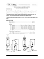
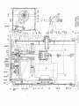
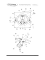
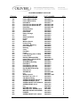
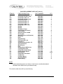
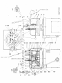
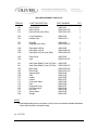
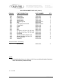
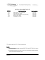
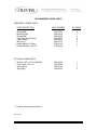
Grand Rapids, Michigan, U.S.A. 49504-5298
USER’S OPERATING AND INSTRUCTION MANUAL
MODEL 625-DR & 625-S
DOUGH DIVIDER / ROUNDERS
0625S20000-CVR
MODEL 625 DOUGH DIVIDER - ROUNDERS
INDEX
DEFINITIONS …………………………………………………………………..… GEN93118
SAFETY INSTRUCTIONS.......................................................................... 0625S20001
DESCRIPTION/SPECIFICATIONS............................................................. 0625S20002
SETUP & OPERATION ..…....................................................................... 0625S25003
Removing the Divider Rounder from the Skid ........................….... 0625S20003-1/3
Adjusting the Main Plate Stop ....................................................... 0625S20003-2/3
Operation ……………….................…............................................ 0625S20003-2/3
MAINTENANCE.......................................................................................... 0625S20004
Cleaning................................................................................……..
Lubrication............................................................................….....
Tightening of V-Belts .....………………….............…......................
Replacing the V-Belts ..........................................................…......
0625S20004-1/4
0625S20004-2/4
0625S20004-3/4
0625S20004-4/4
REPLACEMENT PARTS SECTION
Base Unit Assembly Drawing (Model 625-DR Shown)..... .............. 0625F10000-1/2
Base Unit Assembly Drawing (Model 625-DR Shown).................... 0625F10000-2/2
Base Replacement Parts List ...........…...............................……... 0625S20009-1/2
Base Replacement Parts List ...........…...................................…... 0625S20009-2/2
Arch Assembly Drawing (Model 625-DR Shown)........................……... 0625F10001
Arch Replacement Parts List ...........…...............................….…... 0625S20010-1/2
Arch Replacement Parts List ...........…....................................…... 0625S20010-2/2
Electrical Replacement Parts List ........................................……... 0625S20011-1/2
RECOMMENDED SPARE PARTS LIST.................................................... 0625S20007
WIRING DIAGRAMS ................................................................................. 0625S20008
3/4 HP, 1-60-115 VAC ...........................................................…….. 0625S20008-1/2
3/4 HP, 1-60-208 VAC ...........................................................…..... 0625S20008-1/2
3/4 HP, 1-60-230 VAC ...........................................................…..... 0625S20008-2/2
3/4 HP, 3-60-230 VAC ....………………….............…...................... 0625S20008-2/2
WARRANTY............................................................................................... GEN040225
WARRANTY PROCEDURE…................................................................... GEN040226
RETURNED PARTS POLICY…………………………………………………. GEN 040227
Rev. 4-26-04
0625S20000
GENERAL
DEFINITIONS
The use of the words WARNING, CAUTION, and NOTE in this manual should be guided
by the following.
WARNING
AN OPERATING PROCEDURE, TECHNIQUE, ETC., WHICH MAY
RESULT IN PERSONAL INJURY IF NOT CAREFULLY FOLLOWED.
CAUTION
AN OPERATING PROCEDURE, TECHNIQUE, ETC., WHICH MAY
RESULT IN DAMAGE TO EQUIPMENT IF NOT CAREFULLY FOLLOWED.
NOTE
AN OPERATING PROCEDURE, TECHNIQUE, ETC., WHICH IS CONSIDERED
ESSENTIAL TO EMPHASIZE.
GEN931118
MODEL 625 DOUGH DIVIDER-ROUNDERS
SAFETY INSTRUCTIONS
Every effort has been made by Oliver Products Company to provide you with a safe
machine. It is essential, however, that machine operators and maintenance personnel
observe the following safety precautions. Improper installation or operation of this
equipment may cause personal injury or damage to the equipment.
1. Read this manual before attempting to operate your machine. Never allow an
untrained person to operate or service this machine.
2. Connect the machine to a properly grounded electrical supply that matches the
requirements shown on the electrical specification plate and follow specifications of
local electrical codes.
3. Disconnect and lock-out the machine from the power supply before cleaning or
servicing.
4. Check and secure all guards before starting the machine.
5. Observe all caution and warning labels affixed to the machine.
6. Use only proper replacement parts.
7. Do not wear loose fitting clothing or loose hair. Shirt tails should be tucked in.
8. Wear proper personal safety equipment.
9. Keep Hands away form the moving parts of this machine while it is in operation.
10. In addition to these general safety instructions, also follow the more specific safety
instructions given for the different areas of the machine in the operating instructions.
WARNING
DO NOT USE FOR OTHER THAN ORIGINALLY INTENDED PURPOSE.
Rev. 3-29-02
0625S20001
MODEL 625 DOUGH DIVIDER-ROUNDERS
DESCRIPTION/SPECIFICATIONS
DESCRIPTION
The Model 625 Series of Dough Divider Rounders will divide a pre-weighed amount of
dough into either 15 or 36 equal parts. The same machine will then shape each of the
parts into a convenient ball shape for stamping or baking.
The Model 625 Series of dough Divider Rounders are built of heavy gauge steel and
cast iron. All contact parts are either electroless nickel plated or plastic.
The standard Divider Rounder is driven by a 3/4 HP, TEFC, single phase, capacitor start
motor.
SPECIFICATIONS
Weight (Approx.)--------------------------------------------------------------- 715 lbs.
Shipping Weight --------------------------------------------------------------- 800 lbs.
Electrics:
• Standard-------------------- 3/4 hp, 1 ph, 60 hz, 115 volts, 11.4 amps.
• Optional----------------------- 3/4 hp, 1 ph, 60 hz, 208 volts, 5.7 amps.
• Optional------------------------ 3/4 hp,1 ph, 60 hz, 230 volts, 5.7 amps.
• Optional---------------------- 3/4 hp, 3 ph, 60 hz, 230 volts, 2.6 amps.
• Others-------------------------------------------------------- Consult Factory
Product Weight Range (Approx.)
• 36-Part ---------------------------------------------------------- 1 to 3-1/2 oz.
•
15-Part ----------------------------------------------------- 2-1/2 to 8-1/4 oz.
Physical Size of Machine (plus/minus
1/2"):
Rev. 6-11-02
0625S20002
MODEL 625 DOUGH DIVIDER-ROUNDERS
SETUP & OPERATION
SETUP
Removing the Divider Rounder from the Skid
The first thing to do is to pick a location where the machine will be used. It should have
a grounded power outlet of the same rating as that of the machine and be capable of
carrying the load that the Divider Rounder will put on it. As the Divider Rounder weighs
over 715 pounds we suggest that you next move the crate as near as possible to this
area.
WARNING
THE MACHINE MUST BE CONNECTED TO A PROPERLY GROUNDED
ELECTRICAL SOURCE OF THE SAME RATING AS THE MACHINE.
If you haven't already removed the upper crate do so now. You will find that the Divider
Rounder is bolted to the skid and that the Pressure lever, counter weight, and the four
leveling pads and other components have been shipped loose. Remove the four bolts
from the feet of the machine freeing the Divider Rounder from the skid. Also set to one
side those parts which have been shipped loose.
Carefully raise the machine and remove the skid, or gently slide the machine from the
skid, using care not to tip it over. Locate the machine as near as possible to its
permanent location. Install the legs between the feet of the machine and the cast pads.
Following the installation of the legs and pads, attach the pressure lever and the counter
weight and connect the machine to the power source. After reading the instruction
manual you will be ready to start your machine.
CAUTION
BEFORE ATTEMPTING TO OPERATE THE MACHINE MAKE SURE
THAT ALL OPERATORS HAVE READ THIS MANUAL.
Rev. 6-11-02
0625S20003-1
OPERATING INSTUCTIONS
Adjusting the Main Plate Stop
The only adjustment on the Divider Rounder is the adjustment of the stop for the Main
Plate.
When rounding the divided dough the Main plate is elevated above the Molding Plate to
create a rolling space for the dough. This is done by releasing the Main Plate from the
Gear Shaft using the Releasing Lever. Spring Tension will move the Main Plate above
the Molding Plate to a position set by a stop located on top of the machine. This
distance or stop setting, is determined by the volume of the individual pieces of dough.
More space is required to round a large piece of dough than is required to round a small
piece. Once these settings have been determined we suggest that they be recorded for
future use.
The actual adjustment is made by loosening the large knurled hand locking nut at the
top of the machine and then turning the index screw counter clockwise to raise the plate,
(larger pieces of dough), or clockwise to stop the plate lower for smaller pieces of dough.
After each adjustment, before running the machine, make sure that the index screw has
been secured by tightening the knurled locking nut.
Improper or incomplete rounding can occur either because not enough space has been
allowed or that too much space has been provided. When improper rounding occurs
check this adjustment.
Operation
1. The first step is to weigh a piece of dough which when divided will provide you with
pieces of the desired size. The large piece of dough should weigh either 36 or 15
times, (depending on the option you have chosen), as much as you wish the divided
piece to weigh.
Example: 2-1/4 pounds of dough = 36 one ounce pieces.
4-1/2 pounds of dough = 36 two ounce pieces.
6-3/4 pounds of dough = 36 three ounce pieces.
2.4 pounds of dough = 15 two and a half ounce pieces.
7-3/4 pounds of dough = 15 eight and a quarter ounce pieces.
Place one of the plastic molding plates on a work surface with the circular pockets
facing upward. Place the large piece of weighed dough in the center of the molding
plate and spread it over the plate by hand. The dough should not be spread so that it
lies outside of the large containment ring of the Divider Rounder.
Rev. 3-29-02
0625S20003-2
Operation (Cont’d.)
2. Take the Molding Plate with the dough and place it on the Working Plate of the
machine against the stops in the back and over the alignment pin in the front.
3. Using the Pressure Lever compress the dough firmly to fill the containment ring and to
remove all air.
4. Reduce pressure on the Lever and release the spring loaded Main Plate by actuating
the releasing lever with one hand while maintaining slight pressure on the Pressure
Lever with the other hand.
5. Increase the pressure on the large Pressure Lever and bring it down firmly to the limit
of its travel. This movement will now cut the single large flattened piece of dough into
equal pieces.
6. Again reduce the pressure on the handle but keep it at the bottom of its travel. Turn
the power switch to the "ON" position. Start the rounding action by grasping the
Molding Lever and moving it in a counter clockwise direction as far as it will go. Hold
it in this position for 3 to 5 seconds.
7. Allow the Pressure Lever to return to its normal position. Turn the machine off and
remove the Molding Plate with the rounded pieces of dough. If the pieces are not
rounded properly see the adjustment section of this manual.
Rev. 3-29-02
0625S20003-3
625 DOUGH DIVIDER-ROUNDERS
MODEL 625 DOUGH DIVIDER-ROUNDERS
MAINTENANCE
WARNING
NEVER ATTEMPT TO CLEAN OR SERVICE THIS MACHINE UNTIL IT
HAS BEEN DISCONNECTED FROM THE POWER SUPPLY.
CLEANING
Remove- all scraps from lower pan. Wash all interior surfaces; Knives, pusher plates,
hopper, lid surface with a damp rag and mild soap solution. The exterior and contact
surfaces should be cleaned daily using common cleaners. The knives should be
extended for easier cleaning. This can be done by placing the cleaning separator,
furnished with the machine, Clean the knives and plastic compartment floors of all dough
build-up. Rinse all interior surfaces with a damp rag and clean water. Sanitize all interior
surfaces with a damp rag and sanitizing solution. Air Dry, leave all areas open and allow
interior to air dry before using.
Remember normal maintenance will increase the life of the machine. It is
a good time to inspect the machine for damaged or worn components,
which may later cause problems or interrupt production.
CAUTION
FREQUENT CLEANING OF THE MAIN PLATE, LARGE CONTAINMENT
RING AND KNIFE ARE REQUIRED TO PREVENT DAMAGE TO THE KNIFE.
At the end of the day remove one of the T-pins so that the Arch assembly can be tipped
to one side for easier cleaning. It is best to have two people tip the arch assembly, one
lifting and one catching. After the arch is opened for cleaning actuate the pressure
handle to lower the main plate and knife assembly.
Begin cleaning by dislodging particles of hardened dough with compressed air, a stiff
bristle brush, or a plastic scraper.
CAUTION
NEVER USE WIRE BRUSHES AS DAMAGE TO THE SURFACE PLATING
OF THE CONTACT SURFACES MAY RESULT.
Rev. 3-29-02
0625S20004-1
625 DOUGH DIVIDER-ROUNDERS
CLEANING (cont'd.)
Those particles which can not be removed using the above procedure should be
softened using a spray bottle containing water, or by applying small amounts of
vegetable or mineral oil. Once softened remove these particles with a cloth, stiff bristle
brush or plastic scraper. Clean all cracks, crevices and surfaces of the Main Plate,
Working Plate, and Large Containment Ring. Rinse with a light spray of clean water or a
damp cloth and dry.
Using the releasing lever, release the main plate from the gear shaft so that the
knife will be exposed. Clean the knife using the same cleaning methods as
described above.
Monthly
Once a month, more often in heavy use, the Work Plate should be lifted from the
machine and the area beneath it cleaned of all dough debris, a vacuum works best.
Make sure that when lifting the Work Plate to use care to lift the plate "Straight" up.
NOTE
While the Work Plate is removed it is a good time to complete periodic
lubrication in this area as well. See the lubrication section for details.
Care should be used when replacing the Work Plate. It must be lowered straight down,
making sure that the bearing surface of the rotary carriage's slider enters into the roller
bearing in the Work Plate while at the same time the the guide plate slides between the
four cam followers on the opposite side of the Plate. Make sure that the plate is lowered
completely and is contacting the top surface of the Base Plate.
3 to 6 Months
Remove the Front and Rear covers and blow or brush the area to clean it of flour, dough
and other materials which may have accumulated there.
LUBRICATION
WARNING
NEVER ATTEMPT TO CLEAN OR SERVICE THIS MACHINE UNTIL IT
HAS BEEN DISCONNECTED FROM THE POWER SUPPLY.
NOTE
Always use food approved lubricants when greasing or oiling this machine.
Rev. 3-29-02
0625S20004-2
625 DOUGH DIVIDER-ROUNDERS
LUBRICATION (Cont’d.)
Monthly
Most lubrication should be done monthly and should be completed with the normal
cleaning. Following is a list of things which should be greased or oiled.
1. Monthly, (weekly for machines experiencing heavy usage), grease the fittings on the
left hand side of the machine.
2. Grease the four guide rods on the top of the machine which guide the Large
Containment Ring and Main Plate.
3. Grease the gear on the end of the Pressure Lever and the rack gear if meshes with.
4. After cleaning beneath the Work Plate, (See cleaning section on the previous page),
grease the guide rods for the slider on the Rotatary Carriage.
5. Add a few drops of food approved oil to each of the oilers located around the pivot
for the Pressure Lever on the top of the machine.
TIGHTENING OR REPLACEMENT OF V-BELTS
WARNING
NEVER ATTEMPT TO CLEAN OR SERVICE THIS MACHINE UNTIL IT
HAS BEEN DISCONNECTED FROM THE POWER SUPPLY.
TIGHTENING
To begin, remove the access panel from the right hand side of the machine, (determined
by facing the machine in a normal operating position).
The motor is suspended on a plate mounted to a large shaft suspended from the main
casting above. There are four set collars securing the motor plate on the shaft. The
outer two secure the motors vertical position and should never be loosened unless the
motor is to be removed.
WARNING
LOOSENING THE LOWER SET COLLAR COULD ALLOW THE MOTOR
TO FALL CAUSING PERSONAL INJURY OR DAMAGE TO THE MACHINE.
Rev. 3-29-02
0625S20004-3
625 DOUGH DIVIDER-ROUNDERS
TIGHTENING (Cont’d.)
Loosen the set screws in the two center set collars, (the ones welded to the motor
mounting plate).
Loosen the nut closest to the pivot point on the eyebolt, which passes through the center
of the motor mounting plate. By turning the remaining nut, (which is on the other side of
the mounting plate), clockwise you can increase the tension on the belt. Once desired
tension is achieved secure the motor plate by retightening the nut closest to the pivot of
the eyebolt and the screws in the set collars.
REPLACEMENT
To remove a belt follow the steps above except turn the remaining nut on the eyebolt
counter-clockwise until all tension has been removed from the belt. Swing the eyebolt to
one side and move the motor as close as possible to the driven pulley, thus allowing
removal of the belt.
To replace the belt simply reverse the above procedure and tighten the belt to required
tension as instructed above.
Rev. 3-29-02
0625S20004-4
0625S20012
BASE REPLACEMENT PARTS LIST
ITEM NO.
001
001
002
003
003
006
007
008
009
010
011
012
013
014
015
016
017
018
019
020
021
022
023
024
026
026
027
028
029
030
030
031
032
034
035
039
040
043
045
046
047
049
050
053
063
066
067
068
Rev.11/17/09
PART DESCRIPTION
Frame (Model 625-DR)
Frame (Model 625-S)
Plate-Motor
Panel-Access (Model 625-DR)
Panel-Access (Model 625-S)
Plate-Base
Bracket-Double
Axis-Bracket
Plate-Guide
Rotary Carriage
Slider
Guide-Cylindrical
Pusher
Roller
Washer-Special
Pusher-Long
Axis-Motor Mounting
Piece-Distance
Bushing
Cover
Flat-Plain
Finger
Lever-Molding (5/8-11 THRD)
Lever-Clutch
Bolt-Eye (Model 625-DR)
Holder-Spring (Model 625-S)
Bushing-Flange
Shaft-Motor Mounting
Plate-Work
Plate-Molding (36 Part)
Plate-Molding (15 Part)
Eye Bolt-Motor Mounting
Plate-Anchor
Shaft-Molder
Lug
Washer-Special
Key-Rect 7/16 x 1/2 x 1"
Cap-Plated Tubing
SCREW-HEX HEAD 3/8-16 X ¾
SCREW-HEX HEAD 3/8-16
SCREW-SOCSET CPT #10X3/16
SCREW-HEX HD 1/2-13
Leg
NUT-HEX FULL 3/8-16
WASHER-STST SPRNG LOCK
WASHER-3/8"HELICAL SPRNG
PUSHER
SCREW-SOCSET CPT 1/4X3/8
PART NUMBER
QTY.
0625-0006-1
0625-0006-101
0625-0013
0625-0015-002
0625-0015-001
0625-0007-001
0625-0025
0625-0039
0625-0040
0625-0024
0625-0023
0625-0037
0625-0033
0625-0034
0625-0032
0625-0031
0625-0008
0625-0036
0625-0004
0625-0020
0625-0029
0625-0030
0625-0027
0625-0021
5804-1000
0625-0028-001
0625-0011
0625-0009
0625-0019
5502-4310
5502-4311
0625-0014
0625-0017
0625-0018-001
0625-0041
4655-0215-1401
0625-0035
5902-2112
5842-1552
5842-1555
5842-6120
5843-1105
0625-0070
5832-0027
5851-9361
5851-9010
0625-0033
5842-6133
1
1
1
3
3
1
1
2
1
1
1
2
1
2
1
1
1
1
1
1
2
1
1
1
1
1
1
1
1
3
3
1
2
1
4
4
1
1
2
2
1
4
4
1
4
4
1
2
0625S20009-1
BASE REPLACEMENT PARTS LIST (Cont’d.)
ITEM NO.
PART DESCRIPTION
069
071
072
073
074
075
076
077
078
080
081
082
084
085
088
089
*090
091
094
095
096
098
099
100
102
103
104
110
111
112
113
114
115
120
121
187
SCREW-SOCSET CUPPT 3/8
Pin-Spring 5/16 Dia x 2-1/4"
Pin-Spring 1/4 Dia x 2"
Pin-Spring 3/16 Dia x 1-1/2
Pin-Dowel 3/8 Dia x 1"
Pin-Dowel 3/8 Dia x 2"
Pin-Dowel 3/8 Dia x 3"
Pin-Spring 1/4 Dia x 1"
Pin-Spring 3/8 Dia x 3/4"
Bearing
Bearing
Bearing (for Plate)
Cam Follower (Eccentric)
Cam Follower
Sheave-2 Groove 10.6PD
Bushing-QD
Sheave-2 Groove 1.9PD (60 Hz)
Belt-V A36
Knob
Ring-Retaining
Pin-Cotter 3/32 x 3/4
Collar-Set 1"
Screw-Shoulder 3/8 Dia x 1/2
Spring-Extension
Mount-Shock
Plug
Bearing-Bronze W/Grooves
Coupling-Brass Pipe
Fitting-Brass Street Elbow
Fitting-Straight Grease
Hose-Grease
Fitting-Brass Hose Barb
Clamp-Hose
Pad-Vibra Mount
Grommet-Rubber
Holder-Spring
PART NUMBER
QTY.
5842-6166
5835-6683
5835-6655
5835-6613
5835-6284
5835-6288
5835-6291
5835-6647
5835-6692
5221-0040
5250-4610
5230-4600
5251-0073
5251-0023
5615-3564
5602-0848
5615-3545
5601-1316
5911-7104
5840-1006
5835-6021
5806-7016
5842-2951
7025-5204
0625-0061
5765-8302
0625-0038
5115-1050
5115-1002
5115-7000
5121-9004
5115-2000
5106-8060
5504-0701
5767-1207
0625-0028
2
1
1
8
1
1
1
2
1
2
1
1
2
2
1
1
1
2
1
2
2
2
2
1
4
1
2
2
2
3
2.187”
4
4
4
2
4
NOTE:
•
Numbered drawing items not shown on this list are considered standard
hardware items which can be purchased locally.
*For electrics other than (60 hz) consult factory.
Rev.11/17/09
0625S20009-2
ARCH REPLACEMENT PARTS LIST
ITEM NO.
PART DESCRIPTION
151
151
151
Knife-36 Part
Knife-15 Part
Knife-36 Part (Low Stick)
0625-0001
0625-0001-001
0625-0001-002
1
1
1
152
153
Lever-Releasing
Handle-Gear
0625-0003
0625-0010-1
1
1
157
157
Ring-Big
Ring-Big (Low Stick)
0625-0026
0625-0026-001
1
1
158
158
158
Plate-Main 36 Part
Plate-Main 15 Part
Plate-Main 36 Part (Low Stick)
0625-0002
0625-0002-001
0625-0002-002
1
1
159
160
Plate-Cover
Arch
0625-0052
0625-0016-001
1
1
161
161
Assy-Gear Shaft & Crest (36 Part)
Assy-Gear Shaft & Crest (15 Part)
0625-0005
0625-0005-001
1
1
162
163
168
169
170
171
173
174
175
176
177
178
185
Bolt-Guide
Rod-Guide
Support-Stop
Axis
Holder
Pusher
Connector-Short
Axis
Connector-Long
Pin-Removable
Nut-Lock
Screw-Index
Weight
0625-0056-001
0625-0051-001
0625-0044
0625-0049
0625-0060
0625-0047
0625-0058
0625-0059
0625-0057
0625-0042
0625-0046
0625-0045
0625-0055
2
2
1
2
2
2
2
2
2
2
1
1
1
PART NUMBER
QTY.
NOTE:
• Numbered drawing items not shown on this list are considered standard hardware
items which can be purchased locally.
rev. 11/17/09
0625S20010-1
ARCH REPLACEMENT PARTS LIST (Cont’d.)
ITEM NO.
186
187
188
180
181
182
183
189
190
203
205
215
215
216
218
219
224
225
PART DESCRIPTION
PART NUMBER
QTY.
Spring-Big
Holder-Spring
Cover-Front
Spring-Small
Washer-Special
Axis
Lever-Pressure Formed
Cover-Back
Roller
Bolt
Bolt
Pin-Spring 1/4 Dia x 3/4" (36 Part)
Pin-Spring 1/4 Dia x 7/8" (15 Part)
Pin-Dowel
Screw-Shoulder 1/2 Dia x 3/8
Screw-Shoulder 3/4 Dia x 5/8
Bearing-Bronze
Valve-Oil
7026-5301
0625-0028
5500-5149
7023-4100
0625-0043-001
0625-0054
0625-0012-001
5500-5148
0625-0048
5843-1102
5843-1052
5835-6842
5835-6843
5835-6250
5842-8990
0625-0065
5254-0151
5133-6030
2
4
1
1
1
1
1
1
2
2
2
6
8
1
2
1
4
2
0625-0069
2
Parts Not Shown On Drawing
---
Bracket-Stop
NOTE:
• Numbered drawing items not shown on this list are considered standard hardware
items which can be purchased locally.
rev. 11/17/09
0625S20010-2
ELECTRICAL REPLACEMENT PARTS LIST
ITEM NO.
* 105
* 106
* 107
108
* 109
PART DESCRIPTION
Motor-3/4 HP, 1-60-115/208/230
Starter-Manual, 1 Phase
Heater-Overload SQD # A16.2 (1-60-115)
Bushing-Strain Relief
Cord-Power 1-60-115
PART NUMBER
6301-5602
5709-1125
5708-2438
5765-1082
5765-8302
*For electrics other than (1-60-115vac) consult factory.
NOTES:
• See both assembly drawings numbered 0625F10000 and 0625F10001 for location
of the above parts.
• Numbered drawing items not shown on this list are considered standard hardware
items which can be purchased locally.
0625S20011
RECOMMENDED SPARE PARTS
EMERGENCY SPARE PARTS
PART DESCRIPTION
*
*
Bearing-Ball
Bearing-Roller
Bearing-Ball
Cam Follower (Eccentric)
Cam Follower
Belt-V A36
Starter-Manual, 1 Phase
Element-Heater, 1-60-115
PART NUMBER
NO. REQ'D.
5221-0040
5250-4610
5230-4600
5251-0073
5251-0023
5601-1316
5709-1125
5708-2438
2
1
1
2
2
2
1
1
6301-5602
5765-8302
7023-4100
7026-5301
1
1
1
2
OPTIONAL SPARE PARTS
*
*
Motor 3/4 HP, 1-60-115/208/230
Cord-Power 1-60-115
Spring-Small
Spring-Big
* For other electrics consult factory.
Rev. 5-23-02
0625S20007
MODEL 625 DOUGH DIVIDER-ROUNDERS
WIRING DIAGRAMS
NOTE
Select the Wiring Diagram to be used for your machine based on its
electrical ratings. See the nameplate on the machine for this rating.
For electrics which are not shown please consult the factory.
Machines rated ¾ HP, 1-60-115 VAC:
Machines rated ¾ HP, 1-60-208 VAC:
Rev. 3-29-02
0625S20008-1
Machines rated ¾ HP, 1-60-230 VAC:
Machines rated ¾ HP, 3-60-230 VAC:
Rev. 3-29-02
0625S20008-2
WARRANTY
PARTS
Oliver Packaging & Equipment Company (Oliver) warrants that if any part of the equipment (other
than a part not manufactured by Oliver) proves to be defective (as defined below) within one year
after shipment, and if Buyer returns the defective part to Oliver within one year, Freight Prepaid to
Oliver’s plant in Grand Rapids, MI, then Oliver, shall, at Oliver’s option, either repair or replace the
defective part, at Oliver’s expense.
LABOR
Oliver further warrants that equipment properly installed in accordance with our special instructions,
which proves to be defective in material or workmanship under normal use within one (1) year from
installation or one (1) year and three (3) months from actual shipment date, whichever date comes
first, will be repaired by Oliver or an Oliver Authorized Service Dealer, in accordance with Oliver’s
published Service Schedule.
For purposes of this warranty, a defective part or defective equipment is a part or equipment which is
found by Oliver to have been defective in materials workmanship, if the defect materially impairs the
value of the equipment to Buyer. Oliver has no obligation as to parts or components not
manufactured by Oliver, but Oliver assigns to Buyer any warranties made to Oliver by the
manufacturer thereof.
This warranty does not apply to:
1. Damage caused by shipping or accident.
2. Damage resulting from improper installation or alteration.
3. Equipment misused, abused, altered, not maintained on a regular basis, operated carelessly, or
used in abnormal conditions.
4. Equipment used in conjunction with products of other manufacturers unless such use is approved
by Oliver Products in writing.
5. Periodic maintenance of equipment, including but not limited to lubrication, replacement of wear
items, and other adjustments required due to installation, set up, or normal wear.
6. Losses or damage resulting from malfunction.
The foregoing warranty is in lieu of all other warranties expressed or implied AND OLIVER MAKES
NO WARRANTY OF MERCHANTABILITY OR FITNESS FOR PURPOSE REGARDING THE
EQUIPMENT COVERED BY THIS WARRANTY. Oliver neither assumes nor authorizes any person
to assume for it any other obligations or liability in connection with said equipment. OLIVER SHALL
NOT BE LIABLE FOR LOSS OF TIME, INCONVENIENCE, COMMERCIAL LOSS, INCIDENTAL OR
CONSEQUENTIAL DAMAGES.
GEN 040225
WARRANTY PROCEDURE
1. If a problem should occur, either the dealer or the end user must contact the Parts and
Service Department and explain the problem.
2. The Parts and Service Manager will determine if the warranty will apply to this particular
problem.
3. If the Parts and Service Manager approves, a Work Authorization Number will be
generated, and the appropriate service agency will perform the service.
4. The service dealer will then complete an invoice and send it to the Parts and Service
Department at Oliver Products Company.
5. The Parts and Service Manager of Oliver Packaging and Equipment Company will
review the invoice and returned parts, if applicable, and approve for payment.
GEN 040226
RETURNED PARTS POLICY
This policy applies to all parts returned to the factory whether for warranted credit,
replacement, repair or re-stocking.
Oliver Packaging and Equipment Company requires that the customer obtain a Return
Material Authorization (RMA) number before returning any part. This number should appear
on the shipping label and inside the shipping carton as well. All parts are to be returned
prepaid. Following this procedure will insure prompt handling of all returned parts.
To obtain an RMA number contact the Repair Parts Deptartment toll free at (800) 253-3893.
Parts returned for re-stocking are subject to a RE-STOCKING CHARGE.
Thank you for your cooperation,
Repair Parts Manager
Oliver Packaging and Equipment Company
GEN 040227